HINTERGRUND DER ERFINDUNGBACKGROUND OF THE INVENTION
Gebiet der ErfindungField of the invention
Die vorliegende Erfindung bezieht sich auf eine Fundusbildgebungsvorrichtung und ein Verfahren, und insbesondere auf eine Fundusbildgebungsvorrichtung und ein Bildgebungsverfahren zur Abtastung eines Fundus mit Irradiationslicht zum Erhalten eines Fundusbildes.The present invention relates to a fundus imaging apparatus and method, and more particularly to a fundus imaging apparatus and an imaging method for scanning a fundus of irradiation light to obtain a fundus image.
Beschreibung der verwandten TechnikDescription of the Related Art
Seit den vergangenen Jahren ist die Verwendung einer Fundusbildgebungsvorrichtung zur Abtastung mit Irradiationslicht zum Aufnehmen eines Fundusbildes, wie eines Konfokal-Abtastlaserophthalmoskops (SLO), zum Erhalten eines Steh- oder Bewegtbildes hoher Auflösung als Einrichtung zum Aufnehmen eines Fundusbildes verbreitet. Bei dieser Fundusbildgebungsvorrichtung dauert es einige Zeit vom Beginn bis zum Ende der Bildgebung. Die Bildgebung ist daher für unwillkürlichen Augapfelbewegungen, genannt Flackern, Augapfelbewegungen aufgrund schlechter Fixierung oder die Bewegung des Auges anfällig, die die Bewegung des Gesichts begleitet. Dies macht eine Fundusnachführung zur Nachführung der Bewegung eines Fundus noch wichtiger ( US-Patent Nr. 7,758,189 ).In recent years, the use of an iridium light scanned fundus imaging apparatus for acquiring a fundus image, such as a confocal scanning laser ophthalmoscope (SLO), for obtaining a high-resolution still or moving image as a means for acquiring a fundus image has been popular. In this fundus imaging device, it takes some time from the beginning to the end of the imaging. The imaging is therefore susceptible to involuntary movements of the eyeball, called flickering, eyeball movements due to poor fixation, or the movement of the eye accompanying the movement of the face. This makes a fundus tracking to track the movement of a fund even more important ( U.S. Patent No. 7,758,189 ).
Bei einer derartigen ophthalmologischen Bildgebungsvorrichtung wurde in den vergangenen Jahren ferner eine höhere Auflösung durch die Verwendung einer höheren NA eines Irradiationslasers erreicht. Bei der Aufnahme eines Fundusbildes ist es allerdings erforderlich, das Bild über das optische System des Auges wie Kornea und Linse aufzunehmen. Zusammen mit dem Erreichen einer höheren Auflösung wird der Einfluss von Aberrationen der Kornea und der Linse auf die Bildqualität des aufgenommenen Bildes größer. Daher wurden Studien über ein AO-SLO (Abtastlaserophthalmoskop mit adaptiver Optik) und eine AO-OCT (Optische Kohärenztomographie mit adaptiver Optik) durchgeführt, wobei eine Aberration des Auges gemessen wird und eine adaptive Optik (AO) als optisches Kompensationssystem zum Korrigieren der Aberration in das optische System aufgenommen ist. Beispielsweise beschreibt ” Y. Zhang et al., Optics Express, Band 14, Nr. 10, May 15, 2006 ” ein Beispiel der AO-OCT. Bei dem AO-SLO und der AO-OCT wird für gewöhnlich eine Wellenfront des Auges durch das Shack-Hartmann-Wellenfrontsensorverfahren gemessen, und ein Spiegel mit variabler Form oder ein Ortsphasenmodulator wird zum Korrigieren der gemessenen Wellenfront angesteuert. Durch Aufnahme des Fundusbildes über den Spiegel mit variabler Form oder den Ortsphasenmodulator können das AO-SLO und die AO-OCT ein Bild hoher Auflösung aufnehmen.Further, in such an ophthalmic imaging apparatus, in recent years, higher resolution has been achieved by using a higher NA of an irradiation laser. When taking a fundus image, however, it is necessary to take the image via the optical system of the eye such as cornea and lens. Along with achieving a higher resolution, the influence of aberrations of the cornea and lens on the image quality of the captured image becomes larger. Therefore, studies have been made on an AO-SLO (scanning laser ophthalmoscope with adaptive optics) and AO-OCT (optical coherence tomography with adaptive optics) which measures an aberration of the eye and an adaptive optic (AO) as an optical compensation system for correcting aberration in the optical system is included. For example, " Y. Zhang et al., Optics Express, Vol. 14, No. 10, May 15, 2006 "An example of AO-OCT. In the AO-SLO and the AO-OCT, a wavefront of the eye is usually measured by the Shack-Hartmann wavefront sensor method, and a variable-shape mirror or a spatial phase modulator is driven to correct the measured wavefront. By acquiring the fundus image via the variable-shape mirror or the spatial phase modulator, the AO-SLO and the AO-OCT can acquire a high-resolution image.
Zusammen mit der Verbesserung der Bildgebungsauflösung der Bildgebungsvorrichtung ist es erforderlich, auch die Nachführungsgenauigkeit zur Nachführung einer Bewegung des abzubildenden Fundus zu verbessern. Da die Bewegung des Auges aber kompliziert ist, ist die Durchführung einer Nachführung mit hoher Genauigkeit nur durch die Verwendung der optischen Achsenanpassungseinheit der verwandten Technik, die im US-Patent Nr. 7,758,189 verwendet wird, schwierig.Along with the improvement of the imaging resolution of the imaging device, it is necessary to improve the tracking accuracy for tracking a movement of the fundus to be imaged. However, since the movement of the eye is complicated, the implementation of high accuracy tracking is possible only by the use of the related art optical axis adjusting unit disclosed in U.S. Pat U.S. Patent No. 7,758,189 used, difficult.
KURZZUSAMMENFASSUNG DER ERFINDUNGBRIEF SUMMARY OF THE INVENTION
In Anbetracht des vorstehend angeführten Problems besteht eine Aufgabe der Erfindung in der Realisierung einer sehr genauen Augapfelnachführung in einer Bildgebungsvorrichtung mit hoher Bildgebungsauflösung, wodurch ein Fundusbild mit großer Bildqualität aufgenommen wird.In view of the above-mentioned problem, an object of the invention is to realize highly accurate eye tracking in an imaging apparatus with high imaging resolution, thereby capturing a fundus image with high image quality.
Zur Lösung dieses Problems ist gemäß einem Ausführungsbeispiel der Erfindung eine Bildgebungsvorrichtung bereitgestellt, die eine Bildgebungseinheit zur Irradiation eines Abbildungsbereichs eines Untersuchungsobjekts mit einem ersten Lichtstrahl, der durch eine Abtasteinheit abgelenkt wird, und zur Aufnahme eines Bildes des Untersuchungsobjekts beruhend auf zurückkehrendem Licht des ersten Lichtstrahls, eine Aberrationsmesseinheit zur Messung einer in dem Untersuchungsobjekt erzeugten Aberration, eine Aberrationskorrektureinheit zum Korrigieren der Aberration gemäß der gemessenen Aberration, eine Erfassungseinheit zur Erfassung eines Bewegungsausmaßes des Untersuchungsobjekts, eine Vergleichseinheit zum Vergleichen des erfassten Bewegungsausmaßes mit einem vorbestimmten Schwellenwert, eine Bestimmungseinheit zur Bestimmung entsprechend einem Ergebnis der Bestimmung durch die Bestimmungseinheit zur Änderung des Abbildungsbereichs durch die Verwendung der Abtasteinheit und/oder Verwendung der Aberrationskorrektureinheit, und eine Steuereinheit zur Änderung des Abbildungsbereichs enthält.To solve this problem, according to an embodiment of the present invention, there is provided an imaging apparatus comprising an imaging unit for irradiating an imaging region of an examination subject with a first light beam deflected by a scanning unit and capturing an image of the examination subject based on return light of the first light beam, an aberration measuring unit for measuring an aberration generated in the examination subject, an aberration correction unit for correcting the aberration according to the measured aberration, a detection unit for detecting a movement amount of the examination subject, a comparison unit for comparing the detected movement amount with a predetermined threshold, a determination unit for determining a result the determination by the determination unit for changing the imaging range by the use of the scanning unit and / or Using the Aberrationskorrektureinheit, and contains a control unit for changing the imaging area.
Zur Lösung des vorstehend angeführten Problems ist gemäß einem Ausführungsbeispiel der Erfindung ferner ein Bildgebungsverfahren zur Korrektur einer bei der Abbildung eines Untersuchungsobjekts erzeugten Aberration bereitgestellt. Das Verfahren enthält eine Irradiation eines Abbildungsbereichs mit einem ersten Lichtstrahl, der durch eine Abtasteinheit abgelenkt wird, und ein Aufnehmen eines Bildes des Untersuchungsobjekts beruhend auf zurückkehrendem Licht des ersten Lichtstrahls, Erfassen eines Bewegungsausmaßes des Untersuchungsobjekts, Vergleichen des erfassten Bewegungsausmaßes mit einem vorbestimmten Schwellenwert, Bestimmen gemäß dem Ergebnis des Vergleichs der Änderung des Abbildungsbereichs unter Verwendung der Abtasteinheit und/oder Verwendung einer Aberrationskorrektureinheit und Ändern des Abbildungsbereichs, der mit dem ersten Lichtstrahl zu bestrahlen ist, entsprechend einem Ergebnis der Bestimmung.To solve the above-mentioned problem, according to an embodiment of the invention, there is further provided an imaging method for correcting an aberration generated in imaging an examination subject. The method includes irradiating an imaging area with a first light beam deflected by a scanning unit, and taking an image of the examination subject based on returning light of the first light beam, detecting a movement amount of the examination subject, comparing the detected movement amount with a predetermined threshold, Determining according to the result of the comparison of the change of the imaging area using the scanning unit and / or using an aberration correcting unit and changing the imaging area to be irradiated with the first light beam according to a result of the determination.
Gemäß einem Ausführungsbeispiel der Erfindung ist es möglich, ein Fundusbild mit hoher Auflösung unter geringem Einfluss einer Augapfelbewegung aufzunehmen.According to one embodiment of the invention, it is possible to record a fundus image with high resolution with little influence of an eyeball movement.
Weitere Merkmale der Erfindung werden aus der folgenden Beschreibung der Ausführungsbeispiele unter Bezugnahme auf die beiliegenden Zeichnungen ersichtlich. Jedes nachstehend beschriebene Ausführungsbeispiel der Erfindung kann für sich oder als Kombination einer Vielzahl der Ausführungsbeispiele oder Merkmalen davon bei Bedarf, oder wenn die Kombination von Elementen oder Merkmalen aus einzelnen Ausführungsbeispielen in ein einzelnes Ausführungsbeispiel von Vorteil ist, implementiert werden.Further features of the invention will become apparent from the following description of the embodiments with reference to the accompanying drawings. Each embodiment of the invention described below may be implemented by itself or as a combination of a plurality of the embodiments or features thereof as needed, or when the combination of elements or features of individual embodiments is advantageous in a single embodiment.
KURZBESCHREIBUNG DER ZEICHNUNGENBRIEF DESCRIPTION OF THE DRAWINGS
1 zeigt eine schematische Darstellung eines Aufbaus einer Fundusbildgebungsvorrichtung gemäß einem ersten Ausführungsbeispiel der Erfindung. 1 shows a schematic representation of a structure of a fundus imaging device according to a first embodiment of the invention.
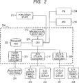
2 zeigt eine schematische Funktionsdarstellung der Fundusbildgebungsvorrichtung gemäß dem ersten Ausführungsbeispiel. 2 shows a schematic functional representation of the fundus imaging device according to the first embodiment.
3 zeigt eine schematische Darstellung eines Prozessablaufs gemäß dem ersten Ausführungsbeispiel. 3 shows a schematic representation of a process flow according to the first embodiment.
Die 4A, 4B und 4C zeigen ausführliche schematische Darstellungen des Prozessablaufs gemäß dem ersten Ausführungsbeispiel.The 4A . 4B and 4C show detailed schematic representations of the process flow according to the first embodiment.
5 zeigt eine schematische Darstellung einer GUI gemäß dem ersten Ausführungsbeispiel. 5 shows a schematic representation of a GUI according to the first embodiment.
6 zeigt eine detaillierte schematische Darstellung des Prozessablaufs gemäß dem ersten Ausführungsbeispiel. 6 shows a detailed schematic representation of the process flow according to the first embodiment.
7 zeigt eine schematische Darstellung eines Aufbaus einer Fundusbildgebungsvorrichtung gemäß einem zweiten Ausführungsbeispiel der Erfindung. 7 shows a schematic representation of a structure of a fundus imaging device according to a second embodiment of the invention.
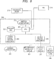
8 zeigt eine schematische Funktionsdarstellung der Fundusbildgebungsvorrichtung gemäß dem zweiten Ausführungsbeispiel. 8th shows a schematic functional representation of the fundus imaging device according to the second embodiment.
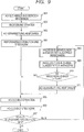
9 zeigt eine schematische Darstellung eines Prozessablaufs gemäß dem zweiten Ausführungsbeispiel. 9 shows a schematic representation of a process flow according to the second embodiment.
BESCHREIBUNG DER AUSFÜHRUNGSBEISPIELEDESCRIPTION OF THE EMBODIMENTS
Nachstehend werden Ausführungsbeispiele der Erfindung beschrieben. Die Erfindung ist aber nicht durch den jeweiligen Aufbau der folgenden Ausführungsbeispiele beschränkt.Hereinafter, embodiments of the invention will be described. However, the invention is not limited by the respective structure of the following embodiments.
Erstes AusführungsbeispielFirst embodiment
Nachstehend wird ein erstes Ausführungsbeispiel der Erfindung beschrieben.Hereinafter, a first embodiment of the invention will be described.
Bei diesem Ausführungsbeispiel wird ein Beispiel beschrieben, in dem eine erste Fundusbildgebungsvorrichtung als Nachführungsvorrichtung verwendet wird, während eine zweite Fundusbildgebungsvorrichtung als adaptive Optik-(AO)-SLO-Vorrichtung verwendet wird. Ein Strahl der Nachführungsvorrichtung und ein Strahl der AO-SLO-Vorrichtung treten gleichzeitig in einen Fundus ein, und Nachführungsdaten werden bei der Steuerung der AO-SLO-Vorrichtung zum Erhalten eines stabilen AO-SLO-Bildes hoher Qualität verwendet.In this embodiment, an example in which a first fundus imaging apparatus is used as the tracking apparatus while a second fundus imaging apparatus is used as the adaptive optics (AO) SLO apparatus will be described. A beam of the tracking device and a beam of the AO-SLO device simultaneously enter a fundus, and tracking data are used in the control of the AO-SLO device to obtain a high-quality stable AO-SLO image.
(Gesamtkonfiguration der Vorrichtung)(Overall configuration of the device)
Nachstehend wird die Fundusbildgebungsvorrichtung gemäß diesem Ausführungsbeispiel unter Bezugnahme auf die schematische Optikdarstellung in 1 beschrieben.Hereinafter, the fundus imaging apparatus according to this embodiment will be described with reference to the schematic optical representation in FIG 1 described.
Die bei diesem Ausführungsbeispiel verwendete Fundusbildgebungsvorrichtung enthält die erste Fundusbildgebungsvorrichtung, die zweite Fundusbildgebungsvorrichtung und eine interne Fixiertargetvorrichtung.The fundus imaging apparatus used in this embodiment includes the first fundus imaging device, the second fundus imaging device, and an internal fixation targeting device.
Die erste Fundusbildgebungsvorrichtung enthält eine Okularlinseneinheit 100 und ein SLO 120. Eine Laserlichtquelle 121 kann geeigneter Weise ein Halbleiterlaser oder eine Superlumineszenzdioden-(SLD)Lichtquelle sein. Zur Verringerung der Helligkeit eines Subjekts und Aufrechterhalten der Auflösung für eine Fundusbeobachtung ist die zu verwendende Wellenlänge geeigneter Weise eine Nahinfrarotwellenlänge im Bereich von 700 nm bis 1.000 nm. Bei diesem Ausführungsbeispiel wird ein Halbleiterlaser mit einer Wellenlänge von 780 nm verwendet. Das von der Laserlichtquelle 121 emittierte Licht geht durch eine Faser 122 in einen Faserkollimator 123 und wird von dem Faserkollimator 123 als kollimierter Lichtstrahl (Messlicht) emittiert.The first fundus imaging device includes an eyepiece lens unit 100 and a SLO 120 , A laser light source 121 may suitably be a semiconductor laser or a superluminescent diode (SLD) light source. For reducing the brightness of a subject and maintaining the resolution for fundus observation, the wavelength to be used is suitably a near-infrared wavelength in the range of 700 nm to 1,000 nm. In this embodiment, a semiconductor laser having a wavelength of 780 nm is used. That of the laser light source 121 emitted light passes through a fiber 122 into a fiber collimator 123 and is from the fiber collimator 123 emitted as a collimated light beam (measuring light).
Der Lichtstrahl wird zu einer SLO-Abtasteinrichtung (X) 128 über eine Linse 124, eine SLO-Abtasteinrichtung (Y) 125 und Weitergabelinsen 126 und 127 geführt. Der Lichtstrahl geht ferner durch eine Abtastlinse 101 und eine Okularlinse 102 zum Eintreten in ein Untersuchungsauge E. Bei diesem Ausführungsbeispiel werden Galvano-Scanner als die SLO-Abtasteinrichtungen (X) 128 und (Y) 125 verwendet.The light beam is sent to a SLO scanner (X) 128 over a lens 124 , a SLO Scanning device (Y) 125 and continueable lenses 126 and 127 guided. The light beam also goes through a scanning lens 101 and an eyepiece lens 102 for entering an examination eye E. In this embodiment, galvano scanners are called the SLO scanners (X). 128 and (Y) 125 used.
Die bei diesem Ausführungsbeispiel zu verwendenden z-, x-, und y-Koordinaten entsprechen jeweils einer Augenachsenrichtung und entsprechen einer horizontalen Richtung und einer vertikalen Richtung bezüglich eines Fundusbildes. Bei diesem Ausführungsbeispiel entspricht die x-Richtung einer Hauptabtastrichtung und die y-Richtung entspricht einer Unterabtastrichtung.The z, x, and y coordinates to be used in this embodiment each correspond to an eye axis direction and correspond to a horizontal direction and a vertical direction with respect to a fundus image. In this embodiment, the x-direction corresponds to a main scanning direction, and the y-direction corresponds to a sub-scanning direction.
Der Lichtstrahl, der in das Untersuchungsauge E eingetreten ist, bestrahlt einen Fundus Ea des Untersuchungsauges E als Punktstrahl. Dieser Punktstrahl wird durch den Fundus Ea des Untersuchungsauges E reflektiert oder gestreut und folgt demselben optischen Weg zur Rückkehr zu einem Ringspiegel 129. Von dem Licht, das den Fundus Ea bestrahlt und reflektiert und gestreut wird, wird das Licht, das durch einen Abschnitt um die Pupille gegangen ist (reflektiertes Licht) durch den Ringspiegel 129 reflektiert und durch eine Avalanchephotodiode (die nachstehend als APD bezeichnet wird) 131 über eine Linse 130 empfangen.The light beam which has entered the examination eye E irradiates a fundus Ea of the examination eye E as a spot beam. This spot beam is reflected or scattered by the fundus Ea of the examination eye E and follows the same optical path to return to a ring mirror 129 , Of the light that irradiates the fundus Ea and is reflected and scattered, the light which has passed through a portion around the pupil (reflected light) through the ring mirror becomes 129 reflected and through an avalanche photodiode (hereinafter referred to as APD) 131 over a lens 130 receive.
Die zweite Fundusbildgebungsvorrichtung enthält die Okularlinseneinheit 100 mit demselben Aufbau wie dem der vorstehend beschriebenen ersten Fundusbildgebungsvorrichtung und eine AO-SLO-Einheit 140 mit einer AO-Einrichtung. Eine Lichtquelle 141 ist eine SLD-Lichtquelle mit einer Wellenlänge von 840 nm. Bei diesem Ausführungsbeispiel teilen sich die Fundusbildgebung und Wellenfrontmessung die Lichtquelle 141, es ist aber möglich, einen Aufbau anzuwenden, bei dem separate Lichtquellen angeordnet sind und Lichtstrahlen in der Mitte optischer Wege kombiniert werden.The second fundus imaging device includes the eyepiece lens unit 100 of the same construction as that of the first fundus imaging apparatus described above and an AO-SLO unit 140 with an AO facility. A light source 141 is an SLD light source with a wavelength of 840 nm. In this embodiment, the fundus imaging and wavefront measurement share the light source 141 However, it is possible to apply a structure in which separate light sources are arranged and light beams are combined in the middle of optical paths.
Das von der Lichtquelle 141 emittierte Licht wird über eine Faser 142 zu einem Faserkollimator 142 übertragen und von dem Faserkollimator 143 als kollimiertes Messlicht abgestrahlt. Das abgestrahlte Messlicht wird durch einen Strahlsplitter 144 transmittiert und zu einem optischen Kompensationssystem geführt.That from the light source 141 emitted light is transmitted through a fiber 142 to a fiber collimator 142 transmitted and from the fiber collimator 143 emitted as a collimated measuring light. The radiated measuring light is transmitted through a beam splitter 144 transmitted and led to an optical compensation system.
Das optische Kompensationssystem enthält einen Strahlsplitter 145, einen Wellenfrontsensor 146 zur Messung einer Aberration, eine Wellenfrontkorrektureinrichtung 148 und Reflexionsspiegel 147-1 bis 147-4 zum Führen des Lichts zu diesen Komponenten. Die Reflexionsspiegel 147-1 bis 147-4 sind derart angeordnet, dass zumindest die Pupille des Untersuchungsauges E und jeder Wellenfrontsensor 146 und die Wellenfrontkorrektureinrichtung 147 eine optisch konjugierte Beziehung haben. Bei diesem Ausführungsbeispiel wird ferner ein Ortsphasenmodulator unter Verwendung eines Flüssigkristallelements als die Wellenfrontkorrektureinrichtung 148 verwendet.The optical compensation system includes a beam splitter 145 , a wavefront sensor 146 for measuring an aberration, a wavefront correction device 148 and reflection mirror 147-1 to 147-4 for guiding the light to these components. The reflection mirror 147-1 to 147-4 are arranged such that at least the pupil of the examination eye E and each wavefront sensor 146 and the wavefront corrector 147 have an optically conjugate relationship. Further, in this embodiment, a spatial phase modulator is used as a wavefront corrector using a liquid crystal element 148 used.
Das Messlicht tritt in die Wellenfrontkorrektureinrichtung 148 ein, um so reflektiert zu werden, und wird zu dem Reflexionsspiegel 147-3 emittiert. Gleichermaßen tritt das Licht, das von dem Fundus Ea des Untersuchungsauges E zurückgekehrt ist, auch in die Wellenfrontkorrektureinrichtung 148 ein, und wird dann zu dem Reflexionsspiegel 147-2 emittiert. Ferner wird das Messlicht durch eine AO-SLO-Abtasteinrichtung (X) 149 und eine AO-SLO-Abtasteinrichtung (Y) 152 zweidimensional abgelenkt. Bei diesem Ausführungsbeispiel wird ein Hochgeschwindigkeitsresonanzscanner (Abtasteinrichtung für die Hauptabtastung) als AO-SLO-Abtasteinrichtung (X) 149 verwendet, und ein Galvano-Scanner (Abtasteinrichtung für die Unterabtastung) wird als AO-SLO-Abtasteinrichtung (Y) 152 verwendet.The measuring light enters the wavefront correction device 148 so as to be reflected, and becomes the reflection mirror 147-3 emitted. Likewise, the light that has returned from the fundus Ea of the examination eye E also enters the wavefront correction device 148 and then becomes the reflection mirror 147-2 emitted. Furthermore, the measuring light is detected by an AO-SLO scanner (X) 149 and an AO-SLO scanner (Y) 152 distracted two-dimensionally. In this embodiment, a high-speed resonance scanner (scanning apparatus for main scanning) is used as an AO-SLO scanner (X). 149 and a galvano scanner (subsampling scanner) is used as the AO-SLO scanner (Y). 152 used.
Das durch die AO-SLO-Abtasteinrichtungen (X) 149 und (Y) 152 abgelenkte Messlicht wird durch einen Strahlsplitter 104 reflektiert und über die Abtastlinse 101 und die Okularlinse 102 zum Eintreten in das Untersuchungsauge E transmittiert. Das Messlicht, das in das Untersuchungsauge E eingetreten ist, wird durch den Fundus Ea reflektiert oder gestreut und folgt demselben optischen Weg zurück zu dem Strahlsplitter 145. Der Strahlsplitter 145 ermöglicht es einem Teil des Messlichts, in den Wellenfrontsensor 146 einzutreten. Der Wellenfrontsensor 146 misst eine Wellenfront des Messlichts und ein Shack-Hartmann-Sensor wird als Wellenfrontsensor 146 verwendet. Ein Teil des reflektierten/gestreuten Lichts, das durch den Strahlsplitter 145 transmittiert wurde, wird dann durch den Strahlsplitter 144 reflektiert und zu einem Lichtintensitätssensor 155, der eine Photomultipliziererröhre (PM) enthält, über einen Faserkollimator 153 und eine Faser 154 geführt.By the AO-SLO scanners (X) 149 and (Y) 152 deflected measuring light is caused by a beam splitter 104 reflected and over the Abtastlinse 101 and the eyepiece lens 102 transmitted to enter the examination eye E. The measuring light which has entered the examination eye E is reflected or scattered by the fundus Ea and follows the same optical path back to the beam splitter 145 , The beam splitter 145 allows a part of the measuring light, in the wavefront sensor 146 enter. The wavefront sensor 146 Measures a wavefront of the measuring light and a Shack-Hartmann sensor is used as a wavefront sensor 146 used. Part of the reflected / scattered light passing through the beam splitter 145 is then transmitted through the beam splitter 144 reflected and to a light intensity sensor 155 containing a photomultiplier tube (PM) via a fiber collimator 153 and a fiber 154 guided.
Das den Lichtintensitätssensor 155 erreichende geführte Licht wird durch den Lichtintensitätssensor 155 in ein elektrisches Signal umgewandelt und durch einen (nicht gezeigten) Steuerabschnitt einer Abbildungsverarbeitung unterzogen. Wenn der Steuerabschnitt den Resonanzscanner (die AO-SLO-Abtasteinrichtung (X) 149) und den Galvano-Scanner (die AO-SLO-Abtasteinrichtung (Y) 152) um einen sehr kleinen Winkel dreht, werden Lichtintensitätsinformationen von einem Abbildungsbereich des Fundus Ea erhalten, und ein Bild wird als das auf einer Anzeigevorrichtung (siehe 2) anzuzeigende Fundusbild unter der Steuerung des Steuerabschnitts aufgebaut. Es wird angemerkt, dass ”sehr kleiner Winkel” einen Winkel kleiner als einen Abtastwinkel des SLO 120 bedeutet.That the light intensity sensor 155 reaching guided light is through the light intensity sensor 155 is converted into an electric signal and subjected to imaging processing by a control section (not shown). When the control section of the resonance scanner (the AO-SLO scanner (X) 149 ) and the galvano scanner (the AO-SLO scanner (Y)) 152 ) rotates at a very small angle, light intensity information is obtained from an imaging area of the fundus Ea, and an image is displayed as that on a display device (see FIG 2 ) to be displayed fundus image under the control of the control section. It is noted that "very small angle" is an angle less than a scan angle of the SLO 120 means.
Der Wellenfrontsensor 146 und die Wellenfrontkorrektureinrichtung 148 sind mit dem Steuerabschnitt verbunden. Der Steuerabschnitt berechnet beruhend auf der durch den Wellenfrontsensor 146 gemessenen Wellenfront ein Modulationsausmaß (Korrekturausmaß) zur Korrektur der Wellenfront in eine Wellenfront ohne Aberration und weist die Wellenfrontkorrektureinrichtung 148 zur Durchführung der Modulation an. Die Messung der Wellenfront und Anweisung für die Wellenfrontkorrektureinrichtung 148 werden wiederholt verarbeitet, wodurch eine Rückkopplungssteuerung derart durchgeführt wird, dass immer eine optimale Wellenfront erhalten wird. Infolgedessen wird die in dem Untersuchungsauge erzeugte Aberration entfernt oder verringert. Bei diesem Ausführungsbeispiel wird als Wellenfrontkorrektureinrichtung 148 ein Reflexionsflüssigkristallortsphasenmodulator von 600×600 Bildelementen verwendet. Als weiteres Beispiel der Wellenfrontkorrektureinrichtung 148 ist ein Spiegel mit variabler Form bekannt, der einen Filmspiegel und eine Vielzahl von Aktuatoren zur Ansteuerung des Spiegels enthält. Sowohl der Flüssigkristallortsphasenmodulator gemäß dem Ausführungsbeispiel als auch der Spiegel mit variabler Form können eine Richtung von Licht lokal auf einer Reflexionsoberfläche oder in einem Durchlassabschnitt ändern, sodass die Wellenfront des durchgelassenen Lichts oder reflektierten Lichts geändert werden kann. The wavefront sensor 146 and the wavefront corrector 148 are connected to the control section. The control section calculates based on the wavefront sensor 146 measured wavefront a modulation amount (correction amount) for correcting the wavefront in a wavefront without aberration and has the wavefront correction device 148 to carry out the modulation. The measurement of the wavefront and instruction for the wavefront correction device 148 are repeatedly processed, whereby a feedback control is performed such that always an optimal wavefront is obtained. As a result, the aberration generated in the examination eye is removed or reduced. In this embodiment, as Wellenfrontkorrektureinrichtung 148 used a reflection liquid crystal phase modulator of 600 x 600 pixels. As another example, the wavefront correction device 148 For example, a variable-shape mirror incorporating a film mirror and a plurality of actuators for controlling the mirror is known. Both the liquid crystal spatial phase modulator according to the embodiment and the variable-shape mirror can change a direction of light locally on a reflection surface or in a transmission portion, so that the wavefront of the transmitted light or reflected light can be changed.
Ein internes Fixiertarget 160 enthält eine Lichtquelle 161 und eine Linse 162. Als Lichtquelle 161 wird eine Vielzahl von in einer Matrix angeordneten Lichtemissionsdioden (LD) verwendet. Eine Einschaltposition der Lichtemissionsdioden wird unter der Steuerung des Steuerabschnitts entsprechend dem Teil geändert, der abgebildet werden soll. Licht von der Lichtquelle 161 wird durch einen Spektralspiegel 103 über die Linse 162 zu dem Untersuchungsauge E geführt. Das von der Lichtquelle 161 emittierte Licht hat 520 nm, und ein gewünschtes Muster wird durch den Steuerabschnitt angezeigt.An internal fixation target 160 contains a light source 161 and a lens 162 , As a light source 161 For example, a plurality of light emission diodes (LD) arranged in a matrix are used. An on position of the light emitting diodes is changed under the control of the control section according to the part to be imaged. Light from the light source 161 is through a spectral mirror 103 over the lens 162 led to the examination eye E. That from the light source 161 emitted light is 520 nm, and a desired pattern is displayed by the control section.
(Funktionsaufbau)(Function configuration)
Nachstehend wird ein Funktionsaufbau gemäß diesem Ausführungsbeispiel unter Bezugnahme auf 2 beschrieben. Ein Steuerabschnitt (PC) 200 zur Steuerung von Funktionselementen enthält eine Anzeigevorrichtung 212, eine CPU 201, eine Speichereinrichtung HDD 202, einen Fixiertargetsteuerabschnitt 203, einen SLO-Steuerabschnitt 210 und einen AO-SLO-Steuerabschnitt 209, die Steuerabschnitte für die jeweilige Vorrichtung darstellen. Unter Anweisungen von der CPU 201 werden eine Anzeigevorrichtung 204 (die der Lichtquelle 161 in 1 entspricht) zur Anzeige des Fixiertargets, eine X-Y-Abtasteinrichtung 205 (die den SLO-Abtasteinrichtungen 125 und 128 in 1 entspricht), eine SLO-Lichtquelle 206 (die der Laserlichtquelle 121 in 1 entspricht) der SLO-Vorrichtung, eine X-Y-Abtasteinrichtung 208 (die den AO-SLO-Abtasteinrichtungen 149 und 152 in 1 entspricht), eine AO-SLO-Lichtquelle 207 (die der Lichtquelle 141 in 1 entspricht) der AO-SLO-Vorrichtung jeweils unter der Steuerung des Fixiertargetsteuerabschnitts 203, des SLO-Steuerabschnitts 210 und des AO-SLO-Steuerabschnitts 209 betrieben. Der Wellenfrontsensor 146 und die Wellenfrontkorrektureinrichtung 148, die Komponenten des optischen Kompensationssystems darstellen, werden auch durch den AO-SLO-Steuerabschnitt 209 gesteuert.Hereinafter, a functional configuration according to this embodiment will be described with reference to FIG 2 described. A control section (PC) 200 for controlling functional elements includes a display device 212 , a CPU 201 , a storage device HDD 202 , a fixation target control section 203 , a SLO control section 210 and an AO-SLO control section 209 representing control sections for the respective device. Under instructions from the CPU 201 become a display device 204 (the light source 161 in 1 corresponds) for displaying the fixing target, an XY scanner 205 (the the SLO scanners 125 and 128 in 1 corresponds), a SLO light source 206 (the laser light source 121 in 1 corresponds) of the SLO device, an XY scanner 208 (the AO-SLO scanners 149 and 152 in 1 corresponds), an AO-SLO light source 207 (the light source 141 in 1 corresponds) of the AO-SLO device under the control of the fixation target control section, respectively 203 , the SLO control section 210 and the AO-SLO control section 209 operated. The wavefront sensor 146 and the wavefront corrector 148 , which are components of the optical compensation system, are also controlled by the AO-SLO control section 209 controlled.
Ferner wird ein Signal von dem Untersuchungsauge E über einen PM 214 (der dem Lichtintensitätssensor 155 in 1 entspricht), der ein Lichtaufnahmeelement der AO-SLO-Vorrichtung ist, und eine APD 215 (die der APD 131 in 1 entspricht) erhalten, die ein Lichtaufnahmeelement der SLO-Vorrichtung ist. Das erhaltene Signal wird durch die CPU 201 in ein Bild umgewandelt und auf der Anzeigevorrichtung 212 angezeigt.Further, a signal from the inspection eye E via a PM 214 (the light intensity sensor 155 in 1 ), which is a light-receiving element of the AO-SLO device, and an APD 215 (the the APD 131 in 1 corresponds), which is a light-receiving element of the SLO device. The received signal is passed through the CPU 201 converted into an image and on the display device 212 displayed.
(Ablauf)(Procedure)
Bei der vorstehend angeführten Vorrichtung wird die SLO-Vorrichtung als erste Fundusbildgebungsvorrichtung zur Nachführung verwendet, und das Nachführungsergebnis wird zu den Abtasteinrichtungen der AO-SLO-Vorrichtung und der Wellenfrontkorrektureinrichtung zurückgeführt, um so das AO-SLO-Bild einer gewünschten Position stabil zu erhalten. Ein entsprechender Ablauf ist in 3 dargestellt. Es wird angemerkt, dass die Verarbeitung durch die CPU 201 ausgeführt wird, wenn nichts anderes gesagt ist.In the above-mentioned device, the SLO device is used as the first fundus imaging device for tracking, and the tracking result is fed back to the scanners of the AO-SLO device and the wavefront correcting device so as to stably obtain the AO-SLO image of a desired position. A corresponding procedure is in 3 shown. It is noted that the processing by the CPU 201 is executed, unless otherwise stated.
Zuerst erhält die erste Fundusbildgebungsvorrichtung ein SLO-Fundusbild durch Ausgabe von Licht von der Laserlichtquelle 121 und empfängt das reflektierte Licht durch die APD 131 in einem Zustand, in dem das Fixiertarget 161 zum Präsentieren für das Untersuchungsauge E eingeschaltet ist (Schritt 301). Die erste Fundusbildgebungsvorrichtung arbeitet als Einheit zur Aufnahme eines Fundusbildes des gesamten Fundus des Untersuchungsauges.First, the first fundus imaging device obtains an SLO fundus image by outputting light from the laser light source 121 and receives the reflected light through the APD 131 in a state where the fixation target 161 for presenting to the examination eye E is turned on (step 301 ). The first fundus imaging device operates as a unit for recording a fundus image of the entire fundus of the examination eye.
Beruhend auf einer Anweisung von einem Bediener von einer (nicht gezeigten) Eingabeeinrichtung wird ein AO-SLO-Abbildungsbereich in dem SLO-Bild bestimmt (Schritt 302). Diese Verarbeitung wird durch einen Modulbereich der CPU 201 ausgeführt, der als erste Bereichseinstelleinheit zum Einstellen eines ersten Bereichs des Untersuchungsauges arbeitet, der mit AO-SLO-Licht als erstem Strahl bestrahlt wird. Der erste Bereich wird beruhend auf dem vorab erhaltenen Fundusbild eingestellt. Der mit dem AO-SLO-Licht abzubildende eingestellte Bereich wird in einem Speicher der CPU 201 gespeichert (Schritt 303).Based on an instruction from an operator from an input device (not shown), an AO-SLO imaging area in the SLO image is determined (step 302 ). This processing is done by a module area of the CPU 201 which operates as a first area setting unit for adjusting a first area of the inspection eye which is irradiated with AO-SLO light as a first beam. The first area is set based on the previously obtained fundus image. The set to be displayed with the AO-SLO light Area is in a memory of the CPU 201 saved (step 303 ).
Aus dem aufgenommenen Fundusbild wird zumindest eine Vorlage zur Nachführung extrahiert (Prozess A: Schritt 304). Insbesondere wird beruhend auf dem durch die erste Bereichseinstelleinheit eingestellten ersten Bereich ein zweiter Bereich des Untersuchungsauges, der mit SLO-Licht zur Nachführung als zweiter Strahl zu bestrahlen ist, eingestellt und als Vorlage extrahiert. Die Einstellung des zweiten Bereichs wird durch einen Modulbereich der CPU 201 ausgeführt, der als zweite Bereichseinstelleinheit arbeitet. Ein bestimmter Bereich um die extrahierte Vorlage wird als Nachführungsabtastbereich bestimmt (Schritt 305).At least one template for tracking is extracted from the recorded fundus image (process A: step 304 ). Specifically, based on the first area set by the first area setting unit, a second area of the inspection eye to be irradiated with SLO light for tracking as the second beam is set and extracted as a template. The setting of the second area is by a module area of the CPU 201 executed, which operates as a second area setting unit. A certain area around the extracted original is determined as a tracking scan area (step 305 ).
Die Bildgebung für ein Fundusbild wird gestartet (Schritt 306), und die AO-SLO-Vorrichtung und die SLO-Vorrichtung werden betrieben. Die AO-SLO-Vorrichtung steuert die X-Y-Abtasteinrichtung 208 zur Abtastung des in Schritt 302 bestimmten Abbildungsbereichs an (Schritt 307), und ein AO-SLO-Signal wird erhalten und in ein Bild umgewandelt (Schritt 309). Insbesondere wird beruhend auf zurückgekehrtem Licht des AO-SLO-Lichts als erster Strahl ein AO-SLO-Bild als erstes Bild des Untersuchungsauges erzeugt. Die Bilderzeugung wird durch einen Modulbereich der CPU 201 ausgeführt, der als erste Erzeugungseinheit arbeitet. Danach wird das AO-SLO-Bild in der HDD 202 gespeichert (Schritt 310).Imaging of a fundus image starts (step 306 ), and the AO-SLO device and the SLO device are operated. The AO-SLO device controls the XY scanner 208 to scan the in step 302 certain imaging area (step 307 ), and an AO-SLO signal is obtained and converted into an image (step 309 ). In particular, based on the returned light of the AO-SLO light, as the first beam, an AO-SLO image is generated as the first image of the examination eye. Imaging is by a module area of the CPU 201 executed, which works as a first generating unit. After that, the AO-SLO image in the HDD 202 saved (step 310 ).
Bei diesem Ausführungsbeispiel wird in Schritt 308 ein Aberrationskorrekturprozess ausgeführt. In dem Aberrationskorrekturprozess wird eine Aberration beruhend auf einem Signal von dem Wellenfrontsensor gemessen, und die Wellenfrontkorrektureinrichtung wird gemäß einem Ergebnis der Aberrationsmessung zur Korrektur der Aberration angesteuert.In this embodiment, in step 308 an aberration correction process is executed. In the aberration correcting process, an aberration is measured based on a signal from the wavefront sensor, and the wavefront correcting means is driven in accordance with a result of the aberration measurement to correct the aberration.
Bei diesem Ausführungsbeispiel wird die gemessene Wellenfront durch eine Zernike-Funktion modelliert und Koeffizienten der Ordnungen werden berechnet. Dann wird ein Modulationsausmaß der Wellenfrontkorrektureinrichtung 148 beruhend auf dem Koeffizienten berechnet. Bei der Berechnung des Modulationsausmaßes wird beruhend auf einem Referenzmodulationsausmaß zum Erzeugen von Formen von Zernike-Ordnungen durch die Wellenfrontkorrektureinrichtung 148 das Referenzmodulationsausmaß mit allen Koeffizienten der gemessenen Zernike-Ordnungen multipliziert, und die Ergebnisse ferner alle zum Erhalten eines endgültigen Modulationsausmaßes integriert. Beim Aufbauen eines optischen Augenkorrektursystems wird im Allgemeinen ein Bereich ungefähr von der ersten bis zur sechsten Ordnung der Zernike-Funktion der gemessenen Wellenfront für die Modellierung verwendet. Beispielsweise gibt die erste Ordnung der Zernike-Funktion horizontale und vertikale Ausbreitungsrichtungen an, und die zweite Ordnung gibt einen Fokus oder Astigmatismus an.In this embodiment, the measured wavefront is modeled by a Zernike function and coefficients of the orders are calculated. Then, a modulation amount of the wavefront correction device becomes 148 calculated based on the coefficient. In the calculation of the modulation amount, based on a reference modulation amount for generating shapes of Zernike orders by the wavefront correcting means 148 the reference modulation amount is multiplied by all the coefficients of the measured Zernike orders, and the results are all further integrated to obtain a final modulation amount. In constructing an optical eye correction system, a range of approximately from the first to the sixth order of the Zernike function of the measured wavefront is generally used for the modeling. For example, the first order of the Zernike function indicates horizontal and vertical directions of propagation, and the second order indicates focus or astigmatism.
In Schritt 308 wird der vorstehend beschriebene Prozess mit einem bestimmten Ausmaß wiederholt und fortgesetzt, bis ein Aberrationsausmaß auf einen willkürlichen Schwellenwert oder darunter verringert wurde. Außerdem kann der Aberrationskorrekturprozess ohne Synchronisation mit der Bildgebung ausgeführt werden.In step 308 For example, the process described above is repeated to a certain extent and continued until an aberration amount is reduced to an arbitrary threshold or less. In addition, the aberration correction process can be performed without synchronization with the imaging.
Unter Verwendung der X-Y-Abtasteinrichtung 205 der SLO-Vorrichtung wird gleichzeitig der in Schritt 305 bestimmte Bereich zum Erhalten eines SLO-Bildes abgetastet (Schritt 311). Das heißt, ein zweites Bild des Untersuchungsauges für die Nachführung wird beruhend auf zurückgekehrtem Licht von dem Untersuchungsauge des vorstehend beschriebenen zweiten Strahls erzeugt. Die Bilderzeugung wird durch einen Modulbereich der CPU 201 ausgeführt, der als zweite Erzeugungseinheit arbeitet.Using the XY scanner 205 the SLO device will be the one in step 305 certain area is scanned to obtain a SLO image (step 311 ). That is, a second image of the inspection eye for tracking is generated based on returned light from the inspection eye of the above-described second beam. Imaging is by a module area of the CPU 201 executed, which operates as a second generating unit.
Bei dem erhaltenen SLO-Bild wird eine Vorlagenüberseinstimmungsanpassung ausgeführt. Durch Vergleichen von Koordinaten der Vorlage mit angepassten Koordinaten wird eine Bewegung des Augapfels (Bewegungsausmaß und Richtung) berechnet (Prozess B: Schritt 312). Dieser Berechnungsprozess wird durch einen Modulbereich der CPU 201 ausgeführt, der als Erfassungseinheit zur Erfassung der Bewegung des Untersuchungsauges beruhend auf dem zweiten Bild arbeitet. Es wird angemerkt, dass die Erfassungseinheit das Bild der als Vorlage extrahierten Region mit dem zweiten Bild vergleicht, das an dieser Stufe neu erzeugt und erhalten wird, um die Bewegung zu erfassen, und auch eine Einheit zur Erfassung der Bewegung des Untersuchungsauges durch den Vergleich enthält.In the obtained SLO image, a template matching adjustment is performed. By comparing coordinates of the template with adjusted coordinates, a movement of the eyeball (movement amount and direction) is calculated (process B: step 312 ). This calculation process is performed by a module area of the CPU 201 executed, which operates as a detection unit for detecting the movement of the examination eye based on the second image. It is noted that the detection unit compares the image of the template extracted region with the second image newly generated and obtained at that stage to detect the movement, and also includes a unit for detecting the movement of the inspection eye by the comparison ,
Als Nächstes werden das erfasste Bewegungsausmaß als das Bewegungsausmaß des Untersuchungsauges und ein vorgeschriebener Wert (m) μm des Bewegungsausmaßes verglichen (Schritt 313). Der vorgeschriebene Wert (m) entspricht einem vorbestimmten Schwellenwert, der mit dem Bewegungsausmaß in dem Vergleichsschritt in Schritt 313 verglichen wird. Der Vergleichsschritt wird durch einen Modulbereich der CPU 201 ausgeführt, der als Vergleichseinheit arbeitet. Wenn das Bewegungsausmaß den vorgeschriebenen Wert (m) nicht überschreitet, geht der Prozess zu Schritt 315 über. Wenn das Bewegungsausmaß den vorgeschriebenen Wert (m) überschreitet, wird das Bewegungsausmaß zur Steuerung einer Korrektur des Abbildungsbereichs der AO-SLO-Vorrichtung verwendet (JA in Schritt 313). Die Korrektur des Abbildungsbereichs wird beruhend auf der erfassten Bewegung des Untersuchungsauges ausgeführt, und dieser Prozess wird durch einen Modulbereich der CPU 201 ausgeführt, der als Korrektureinheit zur Korrektur des ersten Bereichs arbeitet. Das heißt, der hier beschriebene vorgeschriebene Wert (m) wird als Referenzwert zur Bestimmung eingestellt, ob die Anpassung des Abbildungsbereichs durch Nachführung der Bewegung des Augapfels erforderlich ist oder nicht. Außerdem hat der vorgeschriebene Wert (m) einen vorbestimmten Standardwert, kann aber entsprechend dem Untersuchungsauge eingestellt werden. Beispielsweise kann der vorgeschriebene Wert (m) für jedes Untersuchungsauge eingestellt werden, oder kann aus in der Speichereinrichtung HDD 202 gespeicherten Daten gelesen werden.Next, the detected movement amount as the movement amount of the examination eye and a prescribed value (m) μm of the movement amount are compared (step 313 ). The prescribed value (m) corresponds to a predetermined threshold corresponding to the amount of movement in the comparing step in step 313 is compared. The comparison step is through a module area of the CPU 201 executed, which works as a comparison unit. If the amount of movement does not exceed the prescribed value (m), the process goes to step 315 above. When the amount of movement exceeds the prescribed value (m), the amount of movement is used to control a correction of the imaging area of the AO-SLO device (YES in step 313 ). The correction of the imaging area is based on the detected movement of the image Examining eye executed, and this process is performed by a module area of the CPU 201 executed, which works as a correction unit for correcting the first area. That is, the prescribed value (m) described herein is set as a reference value for determining whether the adjustment of the imaging area by tracking the movement of the eyeball is required or not. In addition, the prescribed value (m) has a predetermined standard value, but may be set according to the inspection eye. For example, the prescribed value (m) may be set for each examination eye, or may be set in the storage device HDD 202 stored data are read.
Die in Schritt 314 ausgeführte Korrektur des Abbildungsbereichs (Prozess C), d. h. die Anpassung des Abbildungsbereichs, wird durch Korrektur eines Abtastbereichs einer Abtasteinrichtung als Abtasteinheit und eine Schwenkkorrektur durch eine Aberrationskorrektureinrichtung ausgeführt. Es wird angemerkt, dass die Korrektur des Abtastbereichs als Lichtstrahlirradiationsbereich bei diesem Ausführungsbeispiel geeigneterweise durch Ändern einer Lichtstrahlirradiationsrichtung ausgeführt wird, die Erfindung aber nicht auf dieses Änderungsverfahren beschränkt ist.The in step 314 The correction of the imaging area (process C), that is, the adjustment of the imaging area, is performed by correcting a scanning area of a scanner as a scanning unit and a swivel correction by an aberration correcting device. It is noted that the correction of the scanning range as the light beam iriding region in this embodiment is suitably carried out by changing a light beam irrigation direction, but the invention is not limited to this variation method.
Wenn die AO-SLO-Bildgebung abgeschlossen ist, ist die Verarbeitung beendet (Ja in Schritt 315).When AO-SLO imaging is completed, processing is complete (Yes in step 315 ).
Prozess A von Schritt 304 wird unter Bezugnahme auf 4A beschrieben. Das SLO-Bild und der verbotene Bereich der SLO-Bildgebung werden ausgelesen (Schritt 401). Die Vorlage wird aus dem SLO-Bild außerhalb des verbotenen Bereichs extrahiert (Schritt 402). Die Vorlagenkoordinaten und das Bild werden im Speicher gespeichert (Schritt 403).Process A of step 304 is referring to 4A described. The SLO image and the forbidden area of the SLO imaging are read out (step 401 ). The template is extracted from the SLO image outside the forbidden area (step 402 ). The template coordinates and image are stored in memory (step 403 ).
Prozess B wird unter Bezugnahme auf 4B beschrieben. Das Vorlagenbild und die Koordinaten werden aus dem Speicher ausgelesen (Schritt 410). Das ausgelesene Vorlagenbild und ein neu erhaltenes SLO-Bild werden zur Ausführung der Vorlagenübereinstimmungsanpassung verwendet (Schritt 411). Ein angepasstes Bild und Koordinaten werden im Speicher gespeichert (Schritt 412). Die Bewegung des Fundus (Bewegungsausmaß und Richtung) wird beruhend auf den Vorlagenkoordinaten und den angepassten Koordinaten berechnet (Schritt 413).Process B is explained with reference to 4B described. The template image and the coordinates are read from the memory (step 410 ). The read template image and a newly obtained SLO image are used to perform the template match adjustment (step 411 ). A customized image and coordinates are stored in memory (step 412 ). The movement of the fundus (amount of movement and direction) is calculated based on the template coordinates and the adjusted coordinates (step 413 ).
Prozess C wird unter Bezugnahme auf 4C beschrieben. Das in Schritt 312 berechnete Bewegungsausmaß des Augapfels wird ausgelesen (Schritt 414). Wenn das Bewegungsausmaß des Fundus innerhalb eines vorbestimmten Bereichs liegt, passt die Aberrationskorrektureinrichtung bei diesem Beispiel eine Abbildungsposition an. Wenn das Bewegungsausmaß des Fundus den vorbestimmten Bereich überschreitet, wird der Abtastbereich der Strahlabtasteinheit angepasst. Das heißt, in Schritt 415 wird bestimmt, ob das Bewegungsausmaß des Augapfels einen gegebenen Schwellenwert (n) μm überschreitet. Wenn das Bewegungsausmaß (n) μm überschreitet, geht der Prozess zu Schritt 416 über, und ein Abtastzentrum der Abtasteinrichtung wird beruhend auf dem Bewegungsausmaß des Untersuchungsauges angepasst, um den Strahlirradiationsbereich anzupassen. Der Vorgang in Schritt 415 wird auch als eine Form des erfindungsgemäßen Vergleichsschritts betrachtet. Wenn das Bewegungsausmaß des Augapfels den Schwellenwert (n) nicht überschreitet, wird ein Kippen für die Aberrationskorrektureinrichtung in Schritt 417 angewiesen. Das heißt, der hier beschriebene Schwellenwert (n) wird als Referenzwert zur Bestimmung eingestellt, was für den Nachführungsvorgang des Untersuchungsauges geeigneter ist, eine Betätigung des Galvano-Scanners oder dergleichen zur Änderung des Abbildungsbereichs zur Durchführung der Nachführung oder ein Anweisen eines Kippens durch die Aberrationskorrekturvorrichtung zur Durchführung der Nachführung. Ferner entspricht der Schwellenwert (n) einer Form des vorbestimmten Schwellenwerts im Vergleichsschritt. Wird das Kippen für die Aberrationskorrektureinrichtung angewiesen, kann die Aberrationskorrektureinrichtung zur prompten Ansteuerung gesteuert werden, oder die Korrektureinrichtung kann gesteuert werden, dass sie nach einer Addition einer Aberration erster Ordnung nach Zernike zu der durch den Wellenfrontsensor in dem AO-Prozess in Schritt 308 gemessenen Wellenfront entsprechend dem Bewegungsausmaß des Augapfels angesteuert wird. Der vorstehend beschriebene Schritt 415 entspricht einem Bestimmungsschritt der Bestimmung zur Durchführung einer Änderung des Irradiationsbereichs durch Ändern der Strahlirradiationsrichtung und/oder Änderung des Strahlirradiationsbereichs durch die Aberrationskorrektureinheit entsprechend einem Ergebnis des Vergleichs in Schritt 313, und wird durch einen Modulbereich der CPU 201 ausgeführt, der als Bestimmungseinheit arbeitet. Außerdem entsprechen Schritt 416 und Schritt 417 einem Anpassungsschritt der Anpassung des Strahlirradiationsbereichs und werden durch einen Modulbereich der CPU 201 ausgeführt, der als Anpassungseinheit arbeitet. Nach der Ausführung des vorstehend angeführten Prozesses für die Bewegung des Auges wird eine Steuerung zur Abtastung des Abbildungsbereichs in Schritt 418 ausgeführt.Process C is explained with reference to 4C described. That in step 312 calculated movement amount of the eyeball is read out (step 414 ). When the amount of movement of the fundus is within a predetermined range, the aberration correcting means adjusts an imaging position in this example. When the amount of movement of the fundus exceeds the predetermined range, the scanning range of the beam scanning unit is adjusted. That is, in step 415 It is determined whether the amount of movement of the eyeball exceeds a given threshold (n) μm. When the movement amount (n) exceeds μm, the process goes to step 416 via, and a scan center of the scanner is adjusted based on the amount of movement of the inspection eye to adjust the beam radiation range. The process in step 415 is also considered as a form of the comparative step of the invention. If the amount of movement of the eyeball does not exceed the threshold value (n), tilting of the aberration correcting means in step 417 reliant. That is, the threshold value (n) described herein is set as a reference value for determining what is more suitable for the tracking eye tracking operation, operation of the galvano scanner or the like to change the imaging area to perform tracking, or instructing tilting by the aberration correcting device to carry out the tracking. Further, the threshold value (n) corresponds to a shape of the predetermined threshold in the comparison step. When the tilt for the aberration correcting means is instructed, the aberration correcting means may be controlled for prompt driving, or the correcting means may be controlled to operate after adding a first order aberration to Zernike to that by the wavefront sensor in the AO process in step 308 measured wavefront is controlled according to the extent of movement of the eyeball. The step described above 415 corresponds to a determination step of determining to effect a change in the irradiation range by changing the direction of the radiation beam and / or changing the beam radius of radiation by the aberration correction unit according to a result of the comparison in step 313 , and is through a module area of the CPU 201 executed, which works as a determination unit. In addition, step correspond 416 and step 417 an adapting step of the adjustment of the beam irradiation area and are performed by a module area of the CPU 201 executed, which works as an adjustment unit. After the execution of the above-mentioned process for the movement of the eye, a control for scanning the imaging area in step 418 executed.
Ein weiteres Beispiel des Prozesses C wird unter Bezugnahme auf 6 beschrieben. Eine Historie des in Schritt 312 berechneten Bewegungsausmaßes des Augapfels ist gespeichert, und die Historie wird in Schritt 601 ausgelesen. Eine Frequenzseparierung der Augenbewegung wird beruhend auf der Historie des ausgelesenen Bewegungsausmaßes ausgeführt (Schritt 602). Das heißt, erfasste Positionsinformationen werden einer Frequenzzerlegung wie einer Fourier-Transformation unterzogen, sodass Hochfrequenzkomponenten und Niederfrequenzkomponenten getrennt und aus den Komponenten der Augenbewegung erhalten werden. Es wird angemerkt, dass bei dieser Zerlegung Komponenten mit Frequenzwerten größer als einem bestimmten Schwellenwert als Hochfrequenzkomponenten betrachtet werden, und Komponenten mit Frequenzwerten geringer als dem bestimmten Schwellenwert als Niederfrequenzkomponenten betrachtet werden. Allerdings wird bevorzugt, dass dieser Schwellenwert entsprechend einem Aufbau der Vorrichtung, einem Subjekt und dergleichen geändert wird. Bei diesem Ausführungsbeispiel beträgt der bestimmte Schwellenwert 10 Hz als Anfangswert. Im Allgemeinen ist die Bewegung des Auges hauptsächlich durch eine sogenannte Drift mit einer niedrigen Frequenz und einer großen Bewegung oder Amplitude, einen sogenannten Tremor mit hoher Frequenz und geringer Amplitude und eine sogenannten Saccade mit einer ausfallenden Bewegung belegt. Daher werden durch das vorstehend angeführte Verfahren eine hochfrequente Mikrobewegung und eine niederfrequente große Bewegung getrennt, und jeweils durch verschiedene Einrichtungen korrigiert. In Schritt 603 wird die Kippanweisung für die Aberrationskorrektureinrichtung ausgegeben, um die Hochfrequenzkomponenten zu korrigieren. Die Korrektur kann bei diesem Ausführungsbeispiel auch prompt ausgeführt werden, oder kann zu einem Zeitpunkt der AO-Steuerung ausgeführt werden. Da die Aberrationskorrektureinrichtung im Allgemeinen keine große Bewegung korrigieren kann, kann außerdem ein Verfahren mit einer weiteren Bestimmung des Bewegungsausmaßes und einer Anweisung für die Aberrationskorrektureinrichtung zur Ausführung der Korrektur in einem begrenzten möglichen Bereich angewendet werden, während der verbleibende Teil durch die Steuerung einer anderen Einrichtung korrigiert wird. In Schritt 604 wird eine Mittenposition der Abtastung durch die Abtasteinrichtung eingestellt, um die Niederfrequenzkomponenten zu korrigieren.Another example of the process C will be described with reference to 6 described. A history of in step 312 calculated movement amount of the eyeball is stored, and the history is in step 601 read. A frequency separation of the eye movement becomes based on the history of the read movement amount (step 602 ). That is, detected position information is subjected to frequency decomposition such as Fourier transform so that high-frequency components and low-frequency components are separated and obtained from the components of eye movement. It is noted that in this decomposition, components having frequency values greater than a certain threshold are considered high frequency components, and components having frequency values less than the predetermined threshold are considered low frequency components. However, it is preferable that this threshold value is changed according to a constitution of the apparatus, a subject and the like. In this embodiment, the determined threshold is 10 Hz as the initial value. In general, the movement of the eye is mainly occupied by a so-called drift with a low frequency and a large movement or amplitude, a so-called tremor with high frequency and low amplitude and a so-called Saccade with a failing movement. Therefore, by the above-mentioned method, a high-frequency micro-motion and a low-frequency large-motion are separated, and corrected by different means, respectively. In step 603 For example, the tilt instruction for the aberration correction means is output to correct the high-frequency components. The correction may also be promptly executed in this embodiment, or may be performed at a time of AO control. In addition, since the aberration correcting means can not generally correct a large movement, a method with further determination of the amount of movement and an instruction for the aberration correcting means for executing the correction can be applied in a limited possible range while the remaining portion is corrected by the control of another means becomes. In step 604 a center position of the sampling is set by the sampling means to correct the low frequency components.
Während die AO-SLO-Bildgebung durchgeführt wird, wird auf diese Weise die Nachführung derart durchgeführt, dass ein Bild einer gewünschten Position erhalten werden kann. Dies ermöglicht eine Fotorezeptoranalyse durch Überlagerung von Bildern und eine Blutflussanalyse durch Beobachtung von Blutgefäßen. Während der Bildgebung werden Bilder wie in 5 veranschaulicht auf der Anzeigevorrichtung 212 angezeigt. Ein jüngstes Nachführungsbild 505, ein jüngstes Bild 405, das durch die AO-SLO-Vorrichtung aufgenommen wird, und eine Fixiertargetposition 506 werden auf einem zu Anfang erhaltenen SLO-Bild 501 auf demselben Bildschirm angezeigt, und ein Graph 504 des Bewegungsausmaßes des Augapfels, Wellenfrontsensorinformationen 503 und ein AO-SLO-Bild 502 werden auf der Anzeigevorrichtung angezeigt. Bei diesem Ausführungsbeispiel werden das zu Anfang erhaltene SLO-Bild 501 mit einem Weitwinkel und die Fixiertargetposition 506 als Verfahren der Anzeige der jüngsten Informationen angezeigt, während sie zusammen mit der Bewegung des Augapfels bewegt werden. Als Anzeigeverfahren kann ein Anzeigeverfahren verwendet werden, das eine Bewegung des jüngsten Nachführungsbildes 505 und des AO-SLO-Bildes in dem SLO-Bild 501 mit einem Weitwinkel beinhaltet.In this way, while the AO-SLO imaging is performed, the tracking is performed so that an image of a desired position can be obtained. This allows for photoreceptor analysis by overlaying images and blood flow analysis by observing blood vessels. During imaging, images are like in 5 illustrated on the display device 212 displayed. A recent tracking picture 505 , a recent picture 405 which is picked up by the AO-SLO device and a fixation target position 506 are on an initially obtained SLO image 501 displayed on the same screen, and a graph 504 the amount of movement of the eyeball, wavefront sensor information 503 and an AO-SLO image 502 are displayed on the display device. In this embodiment, the initial SLO image is obtained 501 with a wide angle and the fixation target position 506 displayed as a method of displaying the most recent information as it moves along with the movement of the eyeball. As a display method, a display method that includes a movement of the most recent tracking picture may be used 505 and the AO-SLO image in the SLO image 501 with a wide angle included.
Eine unwillkürliche Augapfelbewegung des Untersuchungsauges ist eine Kombination von Komponenten des Tremors, der Drift und der Saccade. Wird daher ein Versuch zur Korrektur des von der unwillkürlichen Augapfelbewegung betroffenen Bildes durch einen Galvano-Scanner als Anpassungseinheit einer einzigen optischen Achse wie im Stand der Technik unternommen, gibt es eine Schwierigkeit bei der Nachführungsgenauigkeit. Dagegen wird beispielsweise angedacht, die Nachführungsgenauigkeit durch eine weitere optische Achsenanpassungseinheit zu verbessern. Allerdings kann beispielsweise ein Resonanzscanner nicht für eine Nachführung verwendet werden, da die Steuerung einer festen Position schwierig ist. Dagegen korrigiert die Aberrationskorrektureinrichtung von sich aus eine Kippkomponente und hat auch eine optische Achsenanpassungsfunktion, sodass sie eine feine optische Achsenanpassung vornehmen kann. Erfindungsgemäß führt diese Aberrationskorrektureinrichtung eine Nachführung in einer Richtung durch, in der die Abtastung bisher unter Verwendung des Resonanzscanners ausgeführt wurde, wodurch die Nachführungsgenauigkeit in einer Vielzahl von Richtungen verbessert wird.An involuntary eyeball movement of the examination eye is a combination of components of the tremor, the drift, and the saccade. Therefore, if an attempt is made to correct the involuntary eyeball movement image by a galvano scanner as a single optical axis matching unit as in the prior art, there is a difficulty in tracking accuracy. By contrast, for example, it is envisaged to improve the tracking accuracy by means of a further optical axis adaptation unit. However, for example, a resonant scanner can not be used for tracking because the control of a fixed position is difficult. On the other hand, the aberration correcting means itself corrects a tilting component and also has an optical axis matching function so that it can make fine optical axis matching. According to the present invention, this aberration correcting means performs tracking in a direction in which the scanning has been carried out using the resonance scanner, thereby improving the tracking accuracy in a plurality of directions.
Wie vorstehend beschrieben ist es möglich, eine sehr genaue Nachführung in einem Hochauflösungs-AO-SLO durch die Verwendung einer Vielzahl von Einrichtungen für eine Abbildungspositionsanpassung durchzuführen, und es ist möglich, ein AO-SLO-Bild mit hoher Bildqualität zu erhalten. Das heißt, erfindungsgemäß wird die Aberrationskorrektureinrichtung als Wellenfrontkorrektureinrichtung des optischen Kompensationssystems auch als Abbildungspositionsanpassungseinheit verwendet, und so kann eine Augapfelnachführung mit hoher Genauigkeit realisiert werden, und ein Fundusbild mit hoher Bildqualität kann erhalten werden.As described above, it is possible to perform highly accurate tracking in a high-resolution AO-SLO by the use of a plurality of imaging position-matching means, and it is possible to obtain an AO-SLO image with high image quality. That is, according to the present invention, the aberration correcting means is also used as the wavefront correcting means of the optical compensating system as the imaging position adjusting unit, and thus eyeball tracking can be realized with high accuracy, and a fundus image with high image quality can be obtained.
Zweites AusführungsbeispielSecond embodiment
Nachstehend wird ein zweites Ausführungsbeispiel der Erfindung beschrieben.Hereinafter, a second embodiment of the invention will be described.
Bei diesem Ausführungsbeispiel wird ein Beispiel beschrieben, in dem eine Fundusposition aus einem AO-SLO-Bild berechnet wird, und Funduspositionsdaten in einer AO-SLO-Abbildungsbereichsteuerung reflektiert werden, um ein stabiles AO-SLO-Bild mit hoher Bildqualität zu erhalten.In this embodiment, an example will be described in which a fundus position An AO-SLO image is calculated, and fundus position data is reflected in an AO-SLO imaging area control to obtain a stable AO-SLO image with high image quality.
(Gesamtaufbau der Vorrichtung)(Overall structure of the device)
Die Fundusbildgebungsvorrichtung gemäß diesem Ausführungsbeispiel wird unter Bezugnahme auf eine schematische Darstellung der Optik in 7 beschrieben.The fundus imaging device according to this embodiment will be described with reference to a schematic representation of the optics in FIG 7 described.
Die AO-SLO-Vorrichtung und die interne Fixiertargetvorrichtung entsprechen jenen im ersten Ausführungsbeispiel und somit wird auf ihre Beschreibung verzichtet.The AO-SLO device and the internal fixation targeting device are the same as those in the first embodiment, and thus their description is omitted.
Allerdings tritt bei diesem Ausführungsbeispiel Wellenfrontmesslicht für eine Aberrationskorrektur in das Auge E ein. Eine Laserlichtquelle 170 kann geeigneter Weise ein Halbleiterlaser oder eine Superlumineszenzdioden-(SLD)Lichtquelle sein. Die geeigneter Weise zu verwendende Wellenlänge liegt in einem Nahinfrarotwellenlängenbereich von 700 nm bis 1000 nm, der so nahe wie möglich an dem in dem AO-SLO verwendeten liegt. Bei diesem Ausführungsbeispiel wird eine SLD mit einer Wellenlänge von 760 nm verwendet. Das von der Laserlichtquelle 170 emittierte Licht wird durch eine Faser 171 zu einem Faserkollimator 172 transmittiert, und wird von dem Faserkollimator 172 als kollimierter Lichtstrahl (Messlicht) emittiert. Der kollimierte Lichtstrahl wird dann durch den Strahlsplitter 104, die Abtastlinse 101 und die Okularlinse 102 zum Eintreten in das Untersuchungsauge E wie das AO-SLO-Messlicht transmittiert. Beispielsweise ist der Strahlsplitter 104 zum Durchlassen von 50% des Wellenfrontmesslichts und zum Reflektieren von 100% des AO-SLO-Messlichts aufgebaut. Dann ist es möglich, AO-SLO-Signallicht mit minimalem Verlust zu empfangen.However, in this embodiment, wavefront measuring light enters the eye E for aberration correction. A laser light source 170 may suitably be a semiconductor laser or a superluminescent diode (SLD) light source. The suitable wavelength to use is a near-infrared wavelength range of 700 nm to 1000 nm as close as possible to that used in the AO-SLO. In this embodiment, an SLD having a wavelength of 760 nm is used. That of the laser light source 170 emitted light is transmitted through a fiber 171 to a fiber collimator 172 transmits, and is from the fiber collimator 172 emitted as a collimated light beam (measuring light). The collimated light beam is then transmitted through the beam splitter 104 , the scanning lens 101 and the eyepiece lens 102 for entering the examination eye E as the AO-SLO measuring light transmits. For example, the beam splitter 104 for transmitting 50% of the wavefront measuring light and for reflecting 100% of the AO-SLO measuring light. Then it is possible to receive AO-SLO signal light with minimal loss.
Der Strahlsplitter 145 genau vor dem Shack-Hartmann-Sensor 146 als Wellenfrontsensor reflektiert 100% des Wellenfrontmesslichts und lässt 100% des AO-SLO-Messlichts durch. Dann ist es möglich, sowohl die Wellenfrontmessung als auch die Fundusbildgebung mit hoher Leistungsfähigkeit durchzuführen.The beam splitter 145 right in front of the Shack-Hartmann sensor 146 The wavefront sensor reflects 100% of the wavefront measuring light and transmits 100% of the AO-SLO measuring light. Then it is possible to perform both wavefront measurement and fundus imaging with high performance.
Das durch den Fundus Ea reflektierte und gestreute Wellenfrontmesslicht erreicht den Strahlsplitter 145 auf demselben Weg wie das AO-SLO und tritt in den Wellenfrontsensor 146 ein. Der Wellenfrontsensor 146 misst eine Aberration anhand des einfallenden Wellenfrontmesslichts und führt eine AO-Steuerung beruhend auf der Aberration durch.The wavefront measuring light reflected and scattered by the fundus Ea reaches the beam splitter 145 on the same path as the AO-SLO and enters the wavefront sensor 146 one. The wavefront sensor 146 measures an aberration from the incident wavefront measurement light and performs AO control based on the aberration.
(Funktionsaufbau)(Function configuration)
Nachstehend wird ein Funktionsaufbau gemäß diesem Ausführungsbeispiel unter Bezugnahme auf 8 beschrieben. Ein Steuerabschnitt (PC 200) zur Steuerung von Funktionselementen enthält eine Anzeigevorrichtung 212, eine CPU 201, eine Speichereinrichtung HDD 202 und einen Fixiertargetsteuerabschnitt 203 und einen AO-SLO-Steuerabschnitt 209, die Steuerabschnitte für die jeweilige Vorrichtung darstellen. Unter Anweisungen von der CPU 201 werden eine Anzeigevorrichtung 204 (die der Lichtquelle 161 in 7 entspricht) zur Anzeige des Fixiertargets, eine X-Y-Abtasteinrichtung 208 (die den AO-SLO-Abtasteinrichtungen 149 und 152 in 7 entspricht), eine AO-SLO-Lichtquelle 207 (die der Lichtquelle 141 in 7 entspricht) der AO-SLO-Vorrichtung und eine Wellenfrontmesslichtquelle (die der Lichtquelle 170 in 7 entspricht) jeweils unter der Steuerung des Fixiertargetsteuerabschnitts 203 und des AO-SLO-Steuerabschnitts 209 betrieben. Der Wellenfrontsensor 147 und die Wellenfrontkorrektureinrichtung 148, die Komponenten des optischen Kompensationssystems sind, werden durch den AO-SLO-Steuerabschnitt 209 gesteuert.Hereinafter, a functional configuration according to this embodiment will be described with reference to FIG 8th described. A control section (PC 200 ) for controlling functional elements includes a display device 212 , a CPU 201 , a storage device HDD 202 and a fixation target control section 203 and an AO-SLO control section 209 representing control sections for the respective device. Under instructions from the CPU 201 become a display device 204 (the light source 161 in 7 corresponds) for displaying the fixing target, an XY scanner 208 (the AO-SLO scanners 149 and 152 in 7 corresponds), an AO-SLO light source 207 (the light source 141 in 7 corresponds) of the AO-SLO device and a wavefront measuring light source (that of the light source 170 in 7 respectively) under the control of the fixation target control section 203 and the AO-SLO control section 209 operated. The wavefront sensor 147 and the wavefront corrector 148 , which are components of the optical compensation system, are controlled by the AO-SLO control section 209 controlled.
Ferner wird ein Signal von dem Untersuchungsauge E für einen PM 214 (der dem Lichtintensitätssensor 155 in 7 entspricht) erhalten, der ein Lichtaufnahmeelement der AO-SLO-Vorrichtung ist. Das erhaltene Signal wird durch die CPU 201 in ein Bild umgewandelt und auf der Anzeigevorrichtung 212 angezeigt.Further, a signal from the inspection eye E for a PM 214 (the light intensity sensor 155 in 7 corresponds), which is a light receiving element of the AO-SLO device. The received signal is passed through the CPU 201 converted into an image and on the display device 212 displayed.
(Ablauf)(Procedure)
Bei der vorstehend beschriebenen Vorrichtung werden Positionsinformationen aus einem AO-SLO-Bild berechnet und eine entsprechende Positionsänderung wird zu den Abtasteinrichtungen der AO-SLO-Vorrichtung und der Wellenfronkorrektureinrichtung zurückgeführt, um dadurch das AO-SLO-Bild einer gewünschten Position stabil zu erhalten. Ein entsprechender Ablauf ist in 9 veranschaulicht. Es wird angemerkt, dass die Verarbeitung durch die CPU 201 ausgeführt wird, wenn nichts anderes gesagt ist.In the apparatus described above, position information is calculated from an AO-SLO image, and a corresponding position change is fed back to the scanners of the AO-SLO device and the wavefront corrector to thereby stably obtain the AO-SLO image of a desired position. A corresponding procedure is in 9 illustrated. It is noted that the processing by the CPU 201 is executed, unless otherwise stated.
Beruhend auf einer Anweisung von einem Bediener von einer (nicht gezeigten) Eingabeeinrichtung wird zuerst ein AO-SLO-Abbildungsbereich in dem SLO-Bild bestimmt (Schritt 901). In der Praxis wird eine Einschaltposition des Fixiertargets 161 zur Anpassung einer Abbildungsposition verändert.Based on an instruction from an operator from an input device (not shown), an AO-SLO imaging area in the SLO image is first determined (step 901 ). In practice, a switch-on position of the fixation target becomes 161 changed to adapt an imaging position.
Die Bildgebung wird in Schritt 902 gestartet. In diesem Schritt bestrahlt das Wellenfrontmesslicht den Fundus. In Schritt 903 wird ein sequenzieller AO-Prozess ausgeführt. Das heißt, die Wellenfrontkorrektureinrichtung wird beruhend auf dem Signal von dem Wellenfrontsensor zur Korrektur der Aberration angesteuert. In diesem Schritt wird der vorstehend angeführte Prozess mit einem bestimmten Ausmaß wiederholt und wird fortgesetzt, bis ein Aberrationsausmaß auf einen willkürlichen Schwellenwert oder darunter verringert ist. Der Zustand der Aberrationskorrektureinrichtung kann beibehalten werden, wenn das Aberrationsausmaß auf einen bestimmten Schwellenwert verringert wurde, oder der AO-Prozess in der AO-SLO-Bildgebung kann fortgesetzt werden.Imaging is in step 902 started. In this step, the wavefront measuring light irradiates the fundus. In step 903 a sequential AO process is executed. That is, the wavefront corrector will be based on the signal driven by the wavefront sensor to correct the aberration. In this step, the above-mentioned process is repeated to a certain extent and is continued until an aberration amount is reduced to an arbitrary threshold or below. The state of the aberration corrector can be maintained when the amount of aberration has been reduced to a certain threshold, or the AO process in the AO-SLO imaging can be continued.
In Schritt 904 wird das AO-SLO-Bild als Referenz erhalten. Das erhaltene Bild wird als Referenzbild gespeichert. Dieses Referenzbild wird insgesamt als die Vorlage verwendet.In step 904 the AO-SLO image is obtained as a reference. The resulting image is saved as a reference image. This reference image is used as the template as a whole.
Die AO-SLO-Vorrichtung steuert die X-Y-Abtasteinrichtung 208 zur Abtastung des in Schritt 901 bestimmten Abbildungsbereichs an und erhält ein AO-SLO-Signal zur Erzeugung eines Bildes (Schritt 905). Insbesondere erzeugt die AO-SLO-Vorrichtung das AO-SLO-Bild als erstes Bild des Untersuchungsauges beruhend auf zurückkehrendem Licht des AO-SLO-Lichts als erster Strahl. Danach wird das AO-SLO-Bild in der HDD 202 gespeichert (Schritt 906).The AO-SLO device controls the XY scanner 208 to scan the in step 901 specific imaging area and receives an AO-SLO signal to generate an image (step 905 ). In particular, the AO-SLO device generates the AO-SLO image as the first image of the inspection eye based on the returning light of the AO-SLO light as the first beam. After that, the AO-SLO image in the HDD 202 saved (step 906 ).
Zum weiteren Erhalten eines AO-SLO-Bildes wird eine Vorlagenübereinstimmungsanpassung bei dem erhaltenen AO-SLO-Bild ausgeführt, und Koordinaten der Vorlage werden mit den angepassten Koordinaten zur Berechnung der Bewegung des Augapfels (Bewegungsausmaß und Richtung) verglichen (Prozess B: Schritt 908). Ferner erfasst die Erfassungseinheit die Bewegung durch Vergleichen des als die Vorlage gespeicherten Referenzbildes mit dem an dieser Stufe erhaltenen neu erzeugten Bild und enthält auch eine Einheit zur Erfassung der Bewegung des Untersuchungsauges anhand des Vergleichs. Der Vorgang in Schritt 908 als Prozess B ist derselbe wie der Vorgang von Prozess B im ersten Ausführungsbeispiel.To further obtain an AO-SLO image, a template matching adjustment is performed on the obtained AO-SLO image, and coordinates of the template are compared with the adjusted coordinates for calculating the motion of the eyeball (movement amount and direction) (process B: step 908 ). Further, the detection unit detects the movement by comparing the reference image stored as the original with the newly formed image obtained at this stage, and also includes a unit for detecting the movement of the examination eye by the comparison. The process in step 908 as process B is the same as the process of process B in the first embodiment.
Da das AO-SLO-Bild im Allgemeinen einen kleinen Abbildungsbereich aufweist, kann bei einer großen Bewegung des Auges das aufgenommene Bild außerhalb des Abbildungsbereichs des Referenzbildes liegen. Daher kann die große Bewegung des Auges anhand einer Überwachungsfunktion oder dergleichen zur Überprüfung einer Gesichtsposition oder Pupillenposition gemessen werden. Ferner ist es möglich, eine Parallelbewegung und Rotation der Pupillenposition auch durch die Verwendung des Wellenfrontsensors 146 zu erfassen. Daher ist es möglich, eine sehr genaue Positionserfassung unter Verwendung des gemessenen Werts des Wellenfrontsensors zusammen mit dem Fundusbild zur Berechnung der Positionsinformationen durchzuführen.Since the AO-SLO image generally has a small imaging area, with a large movement of the eye, the captured image may be outside the imaging area of the reference image. Therefore, the large movement of the eye can be measured by a monitoring function or the like for checking a face position or pupil position. Further, it is possible to parallel movement and rotation of the pupil position also by the use of the wavefront sensor 146 capture. Therefore, it is possible to perform highly accurate position detection using the measured value of the wavefront sensor together with the fundus image to calculate the position information.
Das hier berechnete Bewegungsausmaß wird zur Steuerung der Abbildungsbereichskorrektur der AO-SLO-Vorrichtung verwendet. Diese Korrektur wird durch eine Abtastbereichskorrektur der Abtasteinrichtung als die Abtasteinheit und der Aberrationskorrektureinrichtung ausgeführt (Prozess C: 909). Der Vorgang in Schritt 909 als Prozess C ist derselbe wie der Vorgang von Prozess C im ersten Ausführungsbeispiel.The amount of movement calculated here is used to control the imaging area correction of the AO-SLO device. This correction is performed by a scanning range correction of the scanner as the scanning unit and the aberration correcting means (process C: 909 ). The process in step 909 as Process C, it is the same as the process of Process C in the first embodiment.
Wenn das Bewegungsausmaß des Fundus einwillkürlicher Schwellenwert (o) μm oder größer ist (Schritt 910), wird angenommen, dass sich ein Aberrationszustand stark verändert. Daher geht der Prozess zu Schritt 911 über, und der AO-Prozess wird erneut ausgeführt. Der AO-Prozess ist derselbe wie der in Schritt 903. Allerdings ist dieser Schritt nicht erforderlich, wenn der AO-Prozess auch während der AO-SLO-Bildgebung ausgeführt wird. Das heißt, der hier beschriebene willkürliche Schwellenwert (o) μm ist ein Schwellenwert zur Bestimmung, ob ein gutes Bild aufgrund einer Änderung der Aberration erhalten werden kann oder nicht, wenn sich der Abbildungsbereich ändert. Wenn das Bewegungsausmaß der Schwellenwert oder kleiner ist, wird erkannt, dass das erhaltene Fundusbild für eine Diagnose verwendet werden kann.If the amount of movement of the fundus is an arbitrary threshold (o) μm or larger (step 910 ), it is assumed that an aberration state changes greatly. Therefore, the process goes to step 911 over, and the AO process is run again. The AO process is the same as the one in step 903 , However, this step is not required if the AO process is also performed during AO-SLO imaging. That is, the arbitrary threshold (o) μm described here is a threshold value for determining whether or not a good image can be obtained due to a change in aberration as the imaging region changes. If the amount of movement is the threshold or less, it is recognized that the resulting fundus image can be used for a diagnosis.
Danach geht der Prozess zu Schritt 905 über, und die AO-SLO-Bildgebung wird fortgesetzt.After that, the process goes to step 905 over, and AO-SLO imaging continues.
Wenn die AO-SLO-Bildgebung beendet ist, ist die Verarbeitung beendet (JA in Schritt 907).When the AO-SLO imaging is finished, the processing is finished (YES in step 907 ).
Ohne Verwendung einer weiteren Fundusbildgebungseinheit, die von dem AO-SLO verschieden ist, ist es wie vorstehend beschrieben möglich, die Abbildungsposition nachzuführen. Durch die Verwendung einer Vielzahl von Einrichtungen für eine Abbildungspositionsanpassung kann eine sehr genaue Nachführung auch in dem Hochauflösungs-AO-SLO ausgeführt werden, und ein AO-SLO-Bild mit hoher Bildqualität kann erhalten werden.As described above, without using another fundus imaging unit other than the AO-SLO, it is possible to track the imaging position. By using a plurality of imaging position adjusting means, highly accurate tracking can also be performed in the high-resolution AO-SLO, and an AO-SLO image with high image quality can be obtained.
(Weitere Ausführungsbeispiele)(Further embodiments)
Die Erfindung kann auch durch die Durchführung der folgenden Verarbeitung realisiert werden. Das heißt, die Verarbeitung beinhaltet die Zufuhr einer Software (eines Programms) zur Realisierung der Funktionen der vorstehend angeführten Ausführungsbeispiele zu einem System oder einer Vorrichtung über ein Netzwerk oder verschiedene Speichermedien und Veranlassen eines Computers (oder einer CPU, einer MPU oder dergleichen) des Systems oder der Vorrichtung zum Lesen und Ausführen des Programms.The invention can also be realized by carrying out the following processing. That is, the processing includes the supply of software (a program) for realizing the functions of the above-mentioned embodiments to a system or a device via a network or various storage media and causing a computer (or CPU, MPU or the like) of the system or the device for reading and executing the program.
Es wird angemerkt, dass die Erfindung nicht auf die vorstehend angeführten Ausführungsbeispiele beschränkt ist, und verschiedentlich modifiziert oder verändert werden kann, ohne von der Erfindung abzuweichen. Beispielsweise wurde in den vorstehend angeführten Ausführungsbeispielen der Fall beschrieben, dass ein zu messendes Objekt ein Auge ist, jedoch kann die Erfindung auch bei zu messenden Objekten wie von Haut oder einem Organ verschieden von einem Auge angewendet werden. In diesem Fall hat die Erfindung ein Ausführungsbeispiel als medizinische Ausrüstung, wie ein Endoskop, anstelle einer ophthalmologischen Vorrichtung. Somit wird bevorzugt, dass die Erfindung als Untersuchungsvorrichtung verstanden wird, die als Beispiel eine ophthalmologische Vorrichtung hat, und das Untersuchungsauge als Ausführungsbeispiel eines Untersuchungsobjekts verstanden wird.It is noted that the invention is not limited to those mentioned above Embodiments is limited, and variously modified or modified, without departing from the invention. For example, in the above-mentioned embodiments, the case where an object to be measured is an eye has been described, but the invention can be applied to objects to be measured such as skin or an organ other than an eye. In this case, the invention has an embodiment as medical equipment, such as an endoscope, instead of an ophthalmic device. Thus, it is preferred that the invention be understood as an examination device, which has as an example an ophthalmological device, and the examination eye is understood as an embodiment of an examination subject.
Obwohl die Erfindung unter Bezugnahme auf Ausführungsbeispiele beschrieben wurde, ist ersichtlich, dass die Erfindung nicht auf die offenbarten Ausführungsbeispiele beschränkt ist.Although the invention has been described with reference to embodiments, it will be understood that the invention is not limited to the disclosed embodiments.
Ein Bildgebungsverfahren zur Korrektur einer Aberration ist bereitgestellt, die bei der Bildgebung eines Untersuchungsobjekts erzeugt wird. Das Bildgebungsverfahren enthält eine Irradiation eines Abbildungsbereichs mit einem ersten Lichtstrahl, der durch eine Abtasteinheit abgelenkt wird, und Aufnehmen eines Bildes des Untersuchungsobjekts beruhend auf zurückgekehrtem Licht des ersten Lichtstrahls, Erfassen eines Bewegungsausmaßes des Untersuchungsobjekts, Vergleichen des erfassten Bewegungsausmaßes mit einem vorbestimmten Schwellenwert und Anpassen des mit dem ersten Lichtstrahl zu bestrahlenden Abbildungsbereichs. Die Anpassung beinhaltet eine Bestimmung entsprechend einem Ergebnis des Vergleichs zur Änderung des Abbildungsbereichs durch die Verwendung der Abtasteinheit und/oder die Verwendung einer Aberrationskorrektureinheit.An aberration correction imaging method is provided that is generated during imaging of an examination subject. The imaging method includes irradiating an imaging area with a first light beam deflected by a scanning unit and capturing an image of the examination subject based on returned light of the first light beam, detecting a motion amount of the examination subject, comparing the detected motion amount with a predetermined threshold, and adjusting the with the first light beam to be irradiated imaging area. The adaptation includes a determination according to a result of the comparison of the change of the imaging area by the use of the scanning unit and / or the use of an aberration correcting unit.
ZITATE ENTHALTEN IN DER BESCHREIBUNG QUOTES INCLUDE IN THE DESCRIPTION
Diese Liste der vom Anmelder aufgeführten Dokumente wurde automatisiert erzeugt und ist ausschließlich zur besseren Information des Lesers aufgenommen. Die Liste ist nicht Bestandteil der deutschen Patent- bzw. Gebrauchsmusteranmeldung. Das DPMA übernimmt keinerlei Haftung für etwaige Fehler oder Auslassungen.This list of the documents listed by the applicant has been generated automatically and is included solely for the better information of the reader. The list is not part of the German patent or utility model application. The DPMA assumes no liability for any errors or omissions.
Zitierte PatentliteraturCited patent literature
-
US 7758189 [0002, 0004] US 7758189 [0002, 0004]
Zitierte Nicht-PatentliteraturCited non-patent literature
-
Y. Zhang et al., Optics Express, Band 14, Nr. 10, May 15, 2006 [0003] Y. Zhang et al., Optics Express, Vol. 14, No. 10, May 15, 2006 [0003]