Die Erfindung bezieht sich auf einen Flüssigkeitsbehälter und ein Flüssigkeitszuführungssystem und betrifft insbesondere einen Flüssigkeitsbehälter mit einer unter Verwendung einer Leuchteinrichtung wie einer Leuchtdiode erfolgenden Zustandsanzeige, wobei der angezeigte Zustand die für eine Tintenstrahlaufzeichnung noch zur Verfügung stehende Tintenmenge in Form des Tintenfüllstands eines Tintenbehälters umfasst.The present invention relates to a liquid container and a liquid supply system, and more particularly, to a liquid container having a status display using a lighting device such as a light emitting diode, the displayed state comprising the amount of ink still available for ink jet recording in the form of the ink level of an ink tank.
Stand der TechnikState of the art
Die US 2002/008724 A1 zeigt eine Tintenpatrone sowie ein Aufzeichnungsgerät zur Verwendung mit dieser Tintenpatrone. Dieser Tintenpatrone wird kontaktlos Energie sowie auch Information zugeführt, auf die die Patrone antworten kann.The US 2002/008724 A1 shows an ink cartridge and a recording device for use with this ink cartridge. This ink cartridge is supplied with contactless energy as well as information to which the cartridge can respond.
Die US 2001/0033316 A1 zeigt eine Einreichung zur Ermittlung des Tintenverbrauches, die eine Vielzahl von Kontaktelementen aufweist, die unterschiedlichen Verbrauchszuständen zugeordnet sind. Die dort gezeigte Einrichtung kann die ermittelten Zustände signalisieren.The US 2001/0033316 A1 shows a submission for determining the ink consumption, which has a plurality of contact elements, which are assigned to different consumption conditions. The device shown there can signal the determined states.
Die US 6,422,675 B1 zeigt einen beweglichen Wagen für ein Aufzeichnungsgerät, das mit einem Leuchtelement versehen ist. Der Drucker ist so gestaltet, dass beim Einschalten desselben das Licht des Leuchtelementes nach außen fällt und die Bewegung des Wagens verfolgt werden kann.The US 6,422,675 B1 shows a movable carriage for a recording device, which is provided with a luminous element. The printer is designed so that when it is turned on the light of the light element falls outward and the movement of the car can be tracked.
Stand der TechnikState of the art
Mit zunehmender Verbreitung von Digitalkameras besteht auch ein zunehmender Bedarf in Bezug auf einen ohne PC-Unterstützung erfolgenden Fotodruck, bei dem eine Digitalkamera direkt mit einem Drucker (einer Aufzeichnungseinrichtung) verbunden wird. Weiterhin wird zunehmend angestrebt, einen solchen Fotodruck zur Datenübertragung durch direkte Einführung eines Informationsträgers in Form einer in eine Digitalkamera entnehmbar einlegbaren Speicherkarte in einen Drucker vorzunehmen (was eine weitere Form eines Druckens ohne PC-Unterstützung darstellt). Im allgemeinen wird der Tintenfüllstand des Tintenbehälters eines Druckers über einen Personalcomputer mit Hilfe einer Anzeige überprüft, was jedoch im Falle eines ohne PC-Unterstützung erfolgenden Druckens nicht möglich ist. Nichtsdestoweniger ist jedoch eine Überprüfung des Tintenfüllstands eines Tintenbehälters auch bei einem ohne PC-Unterstützung erfolgenden Drucken erwünscht, da ein Benutzer hierdurch Kenntnis von einem niedrigen Tintenfüllstand des Tintenbehälters erlangen und diesen Tintenbehälter vor dem Beginn eines Druckvorgangs gegen einen Ersatzbehälter auswechseln kann, sodass sich Probleme in Bezug auf die Druckqualität beim Ausdrucken auf einem Papierblatt vermeiden lassen.With the proliferation of digital cameras, there is also an increasing demand for non-PC photographic printing in which a digital camera is directly connected to a printer (a recording device). Furthermore, it is increasingly desired to make such a photo printing for data transmission by direct introduction of an information carrier in the form of a removable removable in a digital camera memory card in a printer (which represents another form of printing without PC support). In general, the ink level of the ink container of a printer is checked by a personal computer by means of a display, which is not possible in the case of printing without PC support. Nonetheless, checking the ink level of an ink container is desirable even in the case of non-PC printing because a user can thereby become aware of a low ink level of the ink container and replace that ink container with a replacement container before starting a printing operation, thus causing problems in Avoid printing quality when printing on a piece of paper.
Es ist bereits bekannt, ein Anzeigeelement wie eine Leuchtdiode zu verwenden, um dem Benutzer einen solchen Zustand des Tintenbehälters anzuzeigen. Aus der japanischen Patent-Offenlegungsschrift Hei 4-275 156 ist z. B. ein in einen Aufzeichnungskopf integrierter Tintenbehälter mit zwei Leuchtdiodenelementen bekannt, die in Abhängigkeit vom Resttintenfüllstand in zwei Schritten eingeschaltet werden. Ferner ist aus der japanischen Patent-Offenlegungsschrift 2002-301 829 ein Tintenbehälter mit einer Lampe bekannt, die in Abhängigkeit vom Resttintenfüllstand eingeschaltet wird. Aus dieser Druckschrift ist auch die Verwendung von vier Tintenbehältern in Verbindung mit einem Aufzeichnungsgerät bekannt, die jeweils mit derartigen Lampen ausgestattet sind.It is already known to use a display element such as a light emitting diode to indicate to the user such a state of the ink tank. From the Japanese Patent Laid-Open Hei 4-275156 is z. For example, an ink tank integrated with a recording head having two light-emitting elements is known, which are turned on in response to the remaining ink level in two steps. Furthermore, from the Japanese Patent Laid-Open Publication 2002-301,829 an ink container with a lamp is known, which is turned on, depending on the remaining ink level. From this document, the use of four ink containers in conjunction with a recording device are known, each equipped with such lamps.
Weiterhin werden zur Erzielung einer hohen Bildqualität zusätzlich zu den üblichen vier Farbtinten (Schwarz, Gelb, Magenta und Cyan) zunehmend Farbtinten wie Hell-Magentatinte, Hell-Cyantinte und dergleichen verwendet. Darüber hinaus wird die Verwendung von speziellen Farbtinten wie roter Tinte oder blauer Tinte vorgeschlagen. In einem solchen Fall finden somit bei einem Tintenstrahldrucker jeweils 7 bis 8 Farbtintenbehälter Verwendung, so dass sich dann ein Mechanismus zur Verhinderung des Einsetzens der Tintenbehälter in falsche Positionen als zweckmäßig erweist. Aus der US-Patentschrift 6 302 535 ist es in diesem Zusammenhang bekannt, die Tintenbehälter in Bezug auf entsprechende Eingriffskonfigurationen des Druckwagens unterschiedlich auszugestalten, sodass bei der Anbringung der Tintenbehälter an dem Druckwagen eine fehlerhafte Montage (inkorrekte Positionierung) verhindert werden kann.Furthermore, in order to obtain a high image quality, in addition to the usual four color inks (black, yellow, magenta and cyan), color inks such as light magenta ink, light cyan ink and the like are increasingly being used. In addition, the use of special color inks such as red ink or blue ink is proposed. In such a case, an ink-jet printer thus uses 7 to 8 color ink tanks each, so that a mechanism for preventing the insertion of the ink tanks into wrong positions will prove appropriate. From the U.S. Patent 6,302,535 It is known in this context to design the ink containers differently with respect to corresponding engagement configurations of the print carriage, so that incorrect mounting (incorrect positioning) can be prevented when the ink containers are attached to the print carriage.
Auch wenn der Tintenbehälter in der aus der japanischen Patent-Offenlegungsschrift 2002-301 829 bekannten Weise mit einer Lampe ausgestattet ist, muss die hauptgeräteseitige Steuereinrichtung jedoch den Tintenbehälter identifizieren, der nur noch eine geringe Tintenmenge enthält, was die Identifizierung des Tintenbehälters erfordert, dem das Signal zum Einschalten der richtigen Lampe zuzuführen ist. Wenn z. B. der Tintenbehälter in der falschen Stellung angebracht ist, besteht die Gefahr, dass ein niedriger Tintenfüllstand für einen anderen Tintenbehälter angezeigt wird, der noch eine ausreichende Tintenmenge enthält. Die Aufleuchtsteuerung für eine Anzeigeeinrichtung wie eine Lampe muss daher korrekte Informationen bezüglich der Anbringungspositionen der Tintenbehälter umfassen.Even if the ink tank in the out of the Japanese Patent Laid-Open Publication 2002-301,829 However, as is well known in the art, the main device side control means must identify the ink container, which contains only a small amount of ink, which requires the identification of the ink container to which the correct lamp signal is to be applied. If z. For example, if the ink tank is mounted in the wrong position, there is a risk of displaying a low ink level for another ink tank that still contains a sufficient amount of ink. The lighting control for a display device such as a lamp must therefore include correct information regarding the mounting positions of the ink tanks.
In Bezug auf eine konstruktive Ausgestaltung zur Ermittlung der Anbringungsposition eines Tintenbehälters ist eine Struktur bekannt, bei der die jeweilige Konfigurationsrelation zwischen den Anbringungspositionen und den zugehörigen Tintenbehältern in Abhängigkeit von den Anbringungspositionen unterschiedlich ausgestaltet ist. Dies erfordert jedoch die Herstellung von in Abhängigkeit von der jeweiligen Farbe und/oder der Art der verwendeten Tinte unterschiedlich ausgestalteten Tintenbehältern, was sich in Bezug auf die Fertigungseffizienz und/oder die Herstellungskosten nachteilig auswirkt.With regard to a structural configuration for determining the mounting position of an ink container, a structure is known in which the respective configuration relationship between the mounting positions and the associated ink tanks is configured differently depending on the mounting positions. However, this requires the preparation of differently designed ink tanks depending on the respective ink and / or the type of ink used, which is disadvantageous in terms of manufacturing efficiency and / or manufacturing cost.
Eine weitere Maßnahme besteht darin, für jede Anbringungsposition weitgehend unabhängig voneinander eine Signalleitung für einen Stromkreis anzubringen, der dann durch Herstellung der Verbindung zwischen einem elektrischen Kontakt des Tintenbehälters und einem hauptgeräteseitigen elektrischen Kontakt in der Anbringungsposition eines Druckwagens oder dergleichen geschlossen wird. So kann z. B. eine Signalleitung zum Auslesen einer Tintenfarbinformation eines Tintenbehälters aus dem betreffenden Tintenbehälter für die Ansteuerung einer Leuchtdiode bei jeder Anbringungsposition vorgesehen sein, wodurch eine falsche Anbringung des Tintenbehälters festgestellt werden kann, wenn die ausgelesene Farbinformation nicht der Anbringungsposition entspricht.Another measure is to provide, for each mounting position, substantially independent of each other a signal line for a circuit, which is then closed by establishing the connection between electrical contact of the ink container and a main device side electrical contact in the mounting position of a print carriage or the like. So z. For example, a signal line for reading out ink color information of an ink container from the ink tank for driving a light emitting diode may be provided at each mounting position, whereby a wrong mounting of the ink tank can be detected if the read color information does not correspond to the mounting position.
Eine solche Anordnung führt jedoch zu einer höheren Anzahl von Signalleitungen. Wie vorstehend beschrieben, besteht weiterhin bei Tintenstrahldruckern oder dergleichen die Tendenz, zur Verbesserung der Bildqualität die Anzahl der verwendeten Tintenarten zu erhöhen. Eine Vergrößerung der Anzahl von Signalleitungen führt jedoch insbesondere bei solchen Druckern zu steigenden Herstellungskosten. Andererseits kann zur Verringerung der Anzahl von Leiterbahnen die Verwendung einer sogenannten gemeinsamen Signalleitung in Form einer Sammelleitungsverbindung in Betracht gezogen werden, jedoch ermöglicht die einfache Verwendung einer solchen gemeinsamen Signalleitung als Sammelleitungsverbindung keine Bestimmung der Tintenbehälter oder der Anbringungspositionen der Tintenbehälter.However, such an arrangement leads to a higher number of signal lines. As described above, in ink jet printers or the like, there is a tendency to increase the number of types of ink used to improve image quality. An increase in the number of signal lines, however, leads in particular in such printers to increasing production costs. On the other hand, to reduce the number of tracks, the use of a so-called common rail line signal line may be considered, but the simple use of such a common signal line as a bus line does not allow determination of the ink tanks or the mounting positions of the ink tanks.
Beschreibung der ErfindungDescription of the invention
Der Erfindung liegt daher die Aufgabe zu Grunde, einen Tintenbehälter und ein Tintenstrahlaufzeichnungsgerät anzugeben, die eine Bestimmung der Anbringungspositionen für die jeweiligen Tintenbehälter unter Verwendung einer gemeinsamen Signalleitung ermöglichen.It is therefore an object of the invention to provide an ink tank and an ink jet recording apparatus which enable determination of the mounting positions for the respective ink tanks using a common signal line.
Unter Berücksichtigung dieser Aufgabenstellung wird erfindungsgemäß somit ein Tintenbehälter sowie ein Tintenstrahl-Aufzeichnungsgerät mit den Merkmalen der unabhängigen Patentansprüche vorgeschlagen.Taking into account this task, an ink tank and an ink jet recording apparatus with the features of the independent claims is thus proposed according to the invention.
Durch diese Anordnung wird die Lichtabgabe bzw. das Aufleuchten des Leuchtelements auf der Basis eines Signals, das über einen mit einem geräteseitigen Kontakt (Anschlusselement) des Aufzeichnungsgeräts verbundenen Kontakt (Kontaktstück) eines Tintenbehälters (Flüssigkeitsbehälters) zugeführt wird, und der dem Tintenbehälter zugeordneten Information gesteuert, sodass auch bei Zuführung des gleichen Steuersignals über die gemeinsame Signalleitung zu den Tintenbehältern nur bei dem jeweiligen Tintenbehälter mit der passenden individuellen Information die Aufleuchtsteuerung erfolgen kann. Auf diese Weise wird die Aufleuchtsteuerung wie das Einschalten des Leuchtelements nur bei dem passenden Tintenbehälter durchgeführt. Zusätzlich kann die Lichtabgabe-Steuereinrichtung die Leuchtelemente der an dem Druckwagen angeordneten Tintenbehälter bei der Bewegung des Druckwagens aufeinanderfolgend ansteuern bzw. betätigen und eine Einrichtung zur Erfassung der Lichtabgabe vorgesehen werden, sodass eine fehlerhafte Anbringung eines Tintenbehälters festgestellt werden kann, wenn in einer jeweiligen Position kein Licht erfasst wird. Auf diese Weise kann der Benutzer dazu veranlasst werden, den Tintenbehälter in der richtigen Position erneut anzubringen, sodass die jeweiligen Anbringungspositionen der Tintenbehälter ermittelt werden können.By this arrangement, the light emission of the lighting element is controlled on the basis of a signal supplied through a contact (contact piece) of an ink tank (liquid tank) connected to a device-side contact (terminal) of the recording apparatus and the information associated with the ink tank so that even when the same control signal is supplied via the common signal line to the ink containers, the illumination control can take place only with the respective ink container with the appropriate individual information. In this way, the lighting control such as turning on the lighting element is performed only on the mating ink tank. In addition, the light emitting control means may successively drive the light emitting elements of the ink tanks arranged on the carriage during the movement of the carriage and provide means for detecting the light output, so that an erroneous attachment of an ink tank can be detected if no one is in a respective position Light is detected. In this way, the user can be made to reattach the ink container in the proper position, so that the respective mounting positions of the ink containers can be detected.
Obwohl somit eine gemeinsame Signalleitung für eine Vielzahl von Tintenbehälter-Anbringungspositionen zur Steuerung der Lichtabgabe von Anzeigeelementen wie Leuchtdioden Verwendung findet, kann auch in einem solchen Falle die Ansteuerung der Anzeigeelemente in Verbindung mit einer Festlegung der Anbringungspositionen von Flüssigkeitsbehältern wie Tintenbehältern erfolgen.Thus, although a common signal line for a plurality of ink container mounting positions is used for controlling the light output of display elements such as light emitting diodes, in such a case, the driving of the display elements can be done in conjunction with a determination of the mounting positions of liquid containers such as ink tanks.
Weitere Aufgabenstellungen, Merkmale und Vorteile der Erfindung ergeben sich aus der nachstehenden Beschreibung von bevorzugten Ausführungsbeispielen, die in Verbindung mit den zugehörigen Zeichnungen erfolgt. Es zeigen:Other objects, features and advantages of the invention will be apparent from the following description of preferred embodiments, taken in conjunction with the accompanying drawings. Show it:
1 eine Seitenansicht (a), eine Vorderansicht (b) und eine Unteransicht (c) eines Tintenbehälters gemäß einem ersten Ausführungsbeispiel der Erfindung, 1 a side view (a), a front view (b) and a bottom view (c) of an ink tank according to a first embodiment of the invention,
2 einen Sektions-Seitenriss des Tintenbehälters gemäß dem ersten Ausführungsbeispiel der Erfindung, 2 1 is a sectional side elevation of the ink container according to the first embodiment of the invention;
3 schematische Seitenansichten (a) und (b) des Tintenbehälters gemäß dem ersten Ausführungsbeispiel der Erfindung, die die Funktion eines an dem Tintenbehälter vorgesehenen Substrats veranschaulichen, 3 schematic side views (a) and (b) of the ink container according to the first embodiment of the invention, illustrating the function of a provided on the ink container substrate,
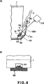
4 eine vergrößerte Ansicht (a) eines wesentlichen Teils des Tintenbehälters gemäß 3 sowie eine Ansicht (b) aus der Richtung IVb, 4 an enlarged view (a) of an essential part of the ink container according to 3 and a view (b) from the direction IVb,
5 eine Seitenansicht (a) und eine Vorderansicht (b) eines Ausführungsbeispiels eines an dem Tintenbehälter des ersten Ausführungsbeispiels angebrachten Steuereinrichtungssubstrats, 5 10 is a side view (a) and a front view (b) of an embodiment of a controller substrate attached to the ink container of the first embodiment;
6 eine Seitenansicht (a) und eine Vorderansicht (b) eines modifizierten Ausführungsbeispiels des an dem Tintenbehälter gemäß dem ersten Ausführungsbeispiel angebrachten Steuereinrichtungssubstrats, 6 3 is a side view (a) and a front view (b) of a modified embodiment of the controller substrate attached to the ink container according to the first embodiment;
7 eine Seitenansicht (a) und eine Vorderansicht (b) eines weiteren modifizierten Ausführungsbeispiels des an dem Tintenbehälter gemäß dem ersten Ausführungsbeispiel angebrachten Steuereinrichtungssubstrats, 7 3 is a side view (a) and a front view (b) of another modified embodiment of the controller substrate attached to the ink container according to the first embodiment;
8 eine Seitenansicht eines Tintenbehälters, die eine Verwendung des Steuereinrichtungssubstrats gemäß 7 veranschaulicht, 8th a side view of an ink container, the use of the controller substrate according to 7 illustrates
9 eine Seitenansicht eines weiteren Ausführungsbeispiels für die Verwendung des Steuereinrichtungssubstrats gemäß 7, 9 a side view of another embodiment of the use of the controller substrate according to 7 .
10 eine Seitenansicht (a) und eine Vorderansicht (b) eines weiteren modifizierten Ausführungsbeispiels des an dem Tintenbehälter gemäß dem ersten Ausführungsbeispiel angebrachten Steuereinrichtungssubstrats, 10 3 is a side view (a) and a front view (b) of another modified embodiment of the controller substrate attached to the ink container according to the first embodiment;
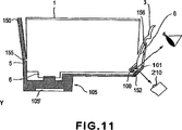
11 eine Seitenansicht, die eine Verwendung des an dem Tintenbehälter vorgesehenen Steuereinrichtungssubstrats gemäß 10 veranschaulicht, 11 12 is a side view illustrating a use of the control device substrate provided on the ink tank according to FIG 10 illustrates
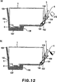
12 eine schematische Seitenansicht, die ein weiteres Ausführungsbeispiel für den Aufbau und die Wirkungsweise eines wesentlichen Teils des Tintenbehälters gemäß dem ersten Ausführungsbeispiel der Erfindung veranschaulicht, 12 FIG. 2 is a schematic side view illustrating another embodiment of the construction and operation of an essential part of the ink tank according to the first embodiment of the invention; FIG.
13 eine Seitenansicht (a) und eine Vorderansicht (b) eines weiteren Ausführungsbeispiels des an dem Tintenbehälter angebrachten Steuereinrichtungssubstrats, 13 a side view (a) and a front view (b) of another embodiment of the mounted on the ink tank controller substrate,
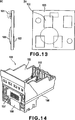
14 eine perspektivische Ansicht, die ein Ausführungsbeispiel einer Aufzeichnungskopfeinheit mit einer Halterung veranschaulicht, in die der Tintenbehälter gemäß dem ersten Ausführungsbeispiel einsetzbar ist, 14 FIG. 15 is a perspective view illustrating an embodiment of a recording head unit having a holder into which the ink container according to the first embodiment is insertable; FIG.
15 eine schematische Seitenansicht, die die Vorgänge des Einsetzens und Entnehmens des Tintenbehälters gemäß dem ersten Ausführungsbeispiel in die Halterung gemäß 14 veranschaulicht, 15 a schematic side view showing the operations of inserting and removing the ink container according to the first embodiment in the holder according to 14 illustrates
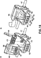
16 perspektivische Ansichten (a) und (b) eines weiteren Ausführungsbeispiels für den Anbringungsbereich des Tintenbehälters gemäß dem ersten Ausführungsbeispiel der Erfindung, 16 perspective views (a) and (b) of another embodiment of the mounting portion of the ink container according to the first embodiment of the invention,
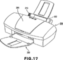
17 eine Außenansicht eines Tintenstrahldruckers, an dem der Tintenbehälter gemäß dem ersten Ausführungsbeispiel anbringbar ist, 17 an external view of an ink-jet printer to which the ink container according to the first embodiment is attachable,
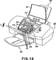
18 eine perspektivische Ansicht des Druckers gemäß 17, bei dem die Gerätezugangsklappe 201 gemäß 17 geöffnet ist, 18 a perspective view of the printer according to 17 where the device access door 201 according to 17 is open,
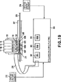
19 ein Blockschaltbild des Aufbaus eines Steuersystems des Tintenstrahldruckers, 19 a block diagram of the structure of a control system of the inkjet printer,
20 die Anordnung einer Signalleitungsführung für eine Signalübertragung zwischen dem Tintenbehälter und einem flexiblen Kabel des Tintenstrahldruckers in Bezug auf das Substrat des Tintenbehälters, 20 the arrangement of a signal line guide for a signal transmission between the ink container and a flexible cable of the inkjet printer with respect to the substrate of the ink container,
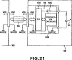
21 ein detailliertes Schaltbild des eine Steuereinrichtung oder dergleichen umfassenden Substrats, 21 12 is a detailed circuit diagram of the substrate including a controller or the like;
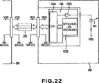
22 ein Schaltbild eines modifizierten Ausführungsbeispiels des Substrats gemäß 21, 22 a circuit diagram of a modified embodiment of the substrate according to 21 .
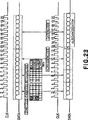
23 ein Steuerdiagramm mit Signalverläufen, die Dateneinschreibvorgänge und Datenlesevorgänge bei einer Speicheranordnung des Substrats veranschaulichen, 23 a control diagram with waveforms illustrating data write operations and data read operations in a storage arrangement of the substrate,
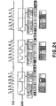
24 ein Steuerdiagramm, das die Aktivierung und Deaktivierung einer Leuchtdiode 101 veranschaulicht, 24 a control diagram showing the activation and deactivation of a light emitting diode 101 illustrates
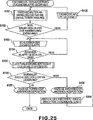
25 ein Ablaufdiagramm, das einen das Einsetzen und Entnehmen des Tintenbehälters gemäß einem Ausführungsbeispiel der Erfindung betreffenden Steuerablauf veranschaulicht, 25 FIG. 3 is a flow chart illustrating a control procedure concerning insertion and removal of the ink tank according to an embodiment of the invention; FIG.
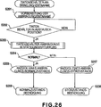
26 ein Ablaufdiagramm eines Einsetz- und Entnahmevorgangs des Tintenbehälters gemäß 25, 26 a flow chart of an insertion and removal operation of the ink container according to 25 .
27 ein Ablaufdiagramm, das eine Anbringungsbestätigungssteuerung gemäß 26 im einzelnen veranschaulicht, 27 FIG. 4 is a flowchart showing an attachment confirmation control according to FIG 26 in detail,
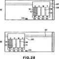
28 einen Zustand (a), bei dem im Rahmen des Steuerablaufs für das Einsetzen und Entnehmen der Tintenbehälter sämtliche Tintenbehälter in korrekten Positionen angebracht und demzufolge die Leuchtdioden jeweils eingeschaltet sind, und einen Zustand (b), der die Bewegung des Druckwagens in eine Position für eine unter Verwendung von Licht erfolgende Validierung (Lichtvalidierung) veranschaulicht, nachdem die Gerätezugangsklappe nach einer Leuchtdioden-Einschaltung geschlossen worden ist, 28 a state (a) in which, as part of the ink container loading and unloading control sequence, all the ink tanks are mounted at correct positions, and thus the LEDs are respectively turned on, and a state (b) indicating the movement of the ink tank Print carriage in a position for using light validation (light validation) after the device access door has been closed after a light-emitting diode switch on,
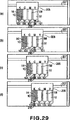
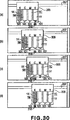
29 einen Lichtvalidierungsablauf (a)–(d), 29 a light validation procedure (a) - (d),
30 einen weiteren Lichtvalidierungsablauf (a)–(d), 30 another light validation procedure (a) - (d),
31 ein Ablaufdiagramm, das einen Aufzeichnungsablauf gemäß einem Ausführungsbeispiel der Erfindung veranschaulicht, 31 FIG. 5 is a flow chart illustrating a recording procedure according to an embodiment of the invention. FIG.
32 den Aufbau eines Tintenbehälters und dessen Anbringungsbereich gemäß einem weiteren Ausführungsbeispiel der Erfindung sowie den Anbringungsablauf (a)–(c), 32 the structure of an ink tank and its mounting portion according to another embodiment of the invention and the mounting sequence (a) - (c),
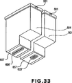
33 eine perspektivische Ansicht, die ein modifiziertes Ausführungsbeispiel des Aufbaus gemäß 32 veranschaulicht, 33 a perspective view showing a modified embodiment of the structure according to 32 illustrates
34 eine perspektivische Ansicht eines Druckers, an dem der Tintenbehälter gemäß diesem weiteren Ausführungsbeispiel der Erfindung anbringbar ist, 34 a perspective view of a printer to which the ink container according to this further embodiment of the invention is attachable,
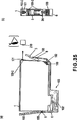
35 eine schematische Seitenansicht (a) und eine schematische Vorderansicht (b) eines Tintenbehälters gemäß einem weiteren Ausführungsbeispiel der Erfindung, 35 a schematic side view (a) and a schematic front view (b) of an ink tank according to another embodiment of the invention,
36 eine schematische Seitenansicht eines modifizierten Ausführungsbeispiels des Aufbaus gemäß 35, 36 a schematic side view of a modified embodiment of the structure according to 35 .
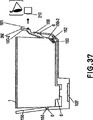
37 eine schematische Seitenansicht eines modifizierten Ausführungsbeispiels des Aufbaus gemäß 35, 37 a schematic side view of a modified embodiment of the structure according to 35 .
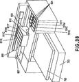
38 eine perspektivische Ansicht eines Druckers mit einem Aufbau gemäß einem weiteren Ausführungsbeispiel der Erfindung, 38 a perspective view of a printer with a structure according to another embodiment of the invention,
39 ein Schaltbild eines Substrats mit einer Steuereinrichtung und dergleichen gemäß einem weiteren Ausführungsbeispiel der Erfindung, und 39 a circuit diagram of a substrate with a control device and the like according to another embodiment of the invention, and
40 ein Steuerdiagramm eines Betriebsablaufs bei diesem Aufbau des Ausführungsbeispiels. 40 a control diagram of an operation in this structure of the embodiment.
Beste Ausführungsform der ErfindungBest embodiment of the invention
Die Erfindung wird nachstehend anhand von Ausführungsbeispielen unter Bezugnahme auf die zugehörigen Zeichnungen in der folgenden Reihenfolge beschrieben:
- 1. Mechanischer Aufbau:
- 1.1 Tintenbehälter
- 1.2 modifiziertes Ausführungsbeispiel
- 1.3 Tintenbehälter-Anbringungsbereich
- 1.4 Aufzeichnungsgerät
- 2. Steuersystem
- 2.1 allgemeiner Aufbau
- 2.2 Verbindungsabschnitt
- 2.3 Steuerablauf
- 3. Weitere Ausführungsbeispiele
The invention will now be described by way of example with reference to the accompanying drawings, in the following order: - 1. Mechanical Structure:
- 1.1 ink tank
- 1.2 modified embodiment
- 1.3 Ink tank mounting area
- 1.4 Recording device
- 2nd tax system
- 2.1 general structure
- 2.2 Connection section
- 2.3 Control process
- 3. Other embodiments
1. Mechanischer Aufbau:1. Mechanical Structure:
1.1 Tintenbehälter (Fig. 1 bis Fig. 5)1.1 Ink tank (Fig. 1 to Fig. 5)
1 zeigt eine Seitenansicht (a), eine Vorderansicht (b) und eine Unteransicht (c) eines Tintenbehälters gemäß einem ersten Ausführungsbeispiel der Erfindung, während 2 einen Sektions-Seitenriss des Tintenbehälters gemäß dem ersten Ausführungsbeispiel der Erfindung zeigt. Im Rahmen der nachstehenden Beschreibung stellt die Vorderseite des Tintenbehälters die Seite dar, die dem den Tintenbehälter handhabenden Benutzer (beim Einsetzen und Entnehmen des Tintenbehälters) zugewandt ist und über die der Benutzer Informationen (durch ein nachstehend noch näher beschriebenes Aufleuchten einer Leuchtdiode) erhält. 1 11 shows a side view (a), a front view (b) and a bottom view (c) of an ink tank according to a first embodiment of the invention, while FIG 2 shows a sectional side elevation of the ink container according to the first embodiment of the invention. In the following description, the front side of the ink container represents the side facing the user handling the ink container (upon insertion and removal of the ink container) and through which the user obtains information (by lighting a light-emitting diode in more detail below).
Wie in 1 dargestellt ist, umfasst der Tintenbehälter 1 gemäß diesem Ausführungsbeispiel ein Arretier- oder Trägerelement 3, das vom unteren Teil seiner Vorderseite ausgeht und aus einem zusammen mit dem Außengehäuse des Tintenbehälters 1 geformten Kunstharzmaterial besteht. Der Tintenbehälter 1 ist hierbei um einen beim Einsetzen des Tintenbehälters 1 in die Behälterhalterung unterstützten Behälterbereich drehbar. Ferner umfasst der Tintenbehälter 1 an seiner Rückseite ein erstes Eingriffselement 5 und an seiner Vorderseite ein zweites Eingriffselement 6, die mit in der Behälterhalterung vorgesehenen Rastelementen in Eingriff bringbar und bei diesem Ausführungsbeispiel in das Arretierelement 3 integriert sind. Durch Herstellung des Eingriffs der Eingriffselemente 5 und 6 mit den zugehörigen Rastelementen wird der Tintenbehälter 1 fest in der Behälterhalterung angebracht. Dieser Anbringungsvorgang wird nachstehend unter Bezugnahme auf 15 noch näher beschrieben.As in 1 is illustrated, the ink container comprises 1 according to this embodiment, a locking or support member 3 which emanates from the lower part of its front side and from one together with the outer casing of the ink tank 1 molded synthetic resin material. The ink tank 1 this is one at the time of insertion of the ink tank 1 Rotatable in the container holder supported container area. Furthermore, the ink container comprises 1 on its back a first engagement element 5 and at its front a second engagement element 6 , which can be brought into engagement with locking elements provided in the container holder and in this embodiment in the locking element 3 are integrated. By making the engagement of the engagement elements 5 and 6 with the associated locking elements, the ink tank 1 firmly mounted in the container holder. This mounting operation will be described below with reference to FIG 15 described in more detail.
An der Unterseite des Tintenbehälters 1 ist ein Tintenzuführungsstutzen 7 zur Tintenzufuhr angeordnet, der bei der Anbringung des Tintenbehälters 1 an der Behälterhalterung mit einer Tinteneinlassöffnung eines nachstehend noch näher beschriebenen Aufzeichnungskopfes verbindbar ist. Ferner ist an der Unterseite des Stützbereichs des Arretierelements 3 ein Basiselement in einer Position vorgesehen, bei der die Unterseite und die Vorderseite ineinander übergehen. Dieses Basiselement kann in Form eines Chips oder eines Plättchens vorgesehen sein und wird im Rahmen der nachstehenden Beschreibung als ”Substrat” 100 bezeichnet.At the bottom of the ink tank 1 is an ink supply nozzle 7 arranged to supply ink when attaching the ink tank 1 is connectable to the container holder with an ink inlet opening of a recording head to be described later. Furthermore, at the bottom of the support region of the locking element 3 a base member provided in a position in which the bottom and the front merge into one another. This base element can be in shape of a chip or a wafer, and will be referred to as "substrate" in the following description. 100 designated.
2 zeigt einen Sektions-Seitenriss des Tintenbehälters 1. Der Innenraum des Tintenbehälters 1 ist aufgeteilt in eine Tintenaufnahmekammer 11 an der Vorderseite, an der sich das Arretierelement 3 und das Substrat 100 befinden, und in eine ein Unterdruck-Erzeugungselement enthaltende Kammer 12 an der Rückseite, die strömungsmechanisch mit dem Tintenzuführungsstutzen 7 in Verbindung steht. Die Tintenaufnahmekammer 11 und die das Unterdruck-Erzeugungselement enthaltende Kammer 12 stehen wiederum strömungsmechanisch über eine Verbindungsöffnung 13 miteinander in Verbindung. Bei diesem Ausführungsbeispiel enthält die Tintenaufnahmekammer 11 nur Tinte, während die das Unterdruck-Erzeugungselement enthaltende Kammer 12 ein Tintenabsorptionsmaterial 15 in Form eines Schwamms, Schaumstoffs, Fasermaterials oder dergleichen enthält, durch dessen Tränkung die Tinte aufgenommen und festgehalten wird (d. h., ein Unterdruck-Erzeugungselement, das bei diesem Ausführungsbeispiel von einem porösen Element gebildet wird). Das poröse Element 15 dient zur Erzeugung eines ausreichenden Unterdrucks zum Ausgleich der von einem in einer Tintenausstoßdüse des Aufzeichnungskopfes gebildeten Meniskus ausgeübten Kraft, um ein Auslaufen (Lecken) von Tinte aus dem Tintenausstoßabschnitt in den Außenbereich zu verhindern und einen zuverlässigen Tintenausstoß bei der Betätigung des Aufzeichnungskopfes zu gewährleisten. 2 shows a section side elevation of the ink container 1 , The interior of the ink tank 1 is divided into an ink receiving chamber 11 at the front, at which the locking element 3 and the substrate 100 and a chamber containing a negative pressure generating element 12 at the rear, fluidically with the ink feed port 7 communicates. The ink receiving chamber 11 and the chamber containing the negative pressure generating element 12 are again fluidically via a connection opening 13 in contact with each other. In this embodiment, the ink accommodating chamber includes 11 only ink while the negative pressure generating element containing chamber 12 an ink absorbent material 15 in the form of a sponge, foam, fibrous material or the like, through the impregnation of which the ink is taken up and held (ie, a negative pressure generating element constituted by a porous member in this embodiment). The porous element 15 serves to generate a sufficient negative pressure to compensate for the force exerted by a meniscus formed in an ink ejection nozzle of the recording head to prevent leakage (leakage) of ink from the ink ejection portion to the outside and to ensure reliable ink ejection upon operation of the recording head.
Der innere Aufbau des Tintenbehälters 1 ist jedoch nicht auf einen solchen unterteilten Aufbau beschränkt, bei dem der Innenraum in die das poröse Element enthaltende Kammer und die nur Tinte enthaltende Aufnahmekammer unterteilt ist. Bei einem anderen Ausführungsbeispiel kann das poröse Element im wesentlichen auch den gesamten Innenraum des Tintenbehälters einnehmen. Ferner ist die den Unterdruck erzeugende Einrichtung nicht auf die Verwendung des porösen Elements beschränkt. Bei einem anderen Ausführungsbeispiel ist nur die Tinte in einem beutel- oder blasenartigen Element aus elastischem Material wie Gummi oder dergleichen enthalten, durch das eine Spannung in Richtung einer Volumenausdehnung erzeugt wird. In diesem Falle wird der Unterdruck durch die Spannung in dem beutel- oder blasenartigen Element zum Festhalten der Tinte erzeugt. Gemäß einem weiteren Ausführungsbeispiel wird zumindest ein Teil des Tintenaufnahmeraums von einem flexiblen Element eingenommen, wobei in diesem Raum nur Tinte enthalten ist und auf das flexible Element eine Federkraft zur Erzeugung eines Unterdrucks ausgeübt wird.The internal structure of the ink tank 1 however, it is not limited to such a divided structure in which the internal space is divided into the chamber containing the porous element and the receiving chamber containing only ink. In another embodiment, the porous element may occupy substantially the entire interior of the ink container. Further, the negative pressure generating means is not limited to the use of the porous member. In another embodiment, only the ink is contained in a bag-like or bubble-like member made of elastic material such as rubber or the like, by which a tension is generated in the direction of volume expansion. In this case, the negative pressure is generated by the tension in the bag or blister-like ink holding member. According to a further embodiment, at least part of the ink accommodating space is occupied by a flexible member, in which space only ink is contained and on the flexible member a spring force for generating a negative pressure is exerted.
Der Boden der Tintenaufnahmekammer 11 ist mit einem Nachweiselement 17 versehen, das in einer einem (in dem Gerät vorgesehenen und nachstehend noch näher beschriebenen) Sensor gegenüberliegenden Position zur Erfassung eines Resttintenfüllstands des an dem Gerät angebrachten Tintenbehälters 1 angeordnet ist. Bei diesem Ausführungsbeispiel ist der Resttintenfüllstandssensor in Form eines Fotosensors mit einem Leuchtelement und einem Lichtempfangselement vorgesehen. Das Nachweiselement 17 besteht aus einem transparenten oder halbtransparenten Material, sodass das von dem Leuchtelement abgegebene Licht bei nicht mehr vorhandener Tinte in geeigneter Weise in Richtung des Lichtempfangselements reflektiert wird, was (in einer nachstehend noch näher beschriebenen Weise) durch einen schrägen Oberflächenabschnitt mit einer zu diesem Zweck vorgesehenen Konfiguration, einem entsprechenden Winkel oder dergleichen herbeigeführt wird.The bottom of the ink receiving chamber 11 is with a detection element 17 provided in a position opposite to a sensor (provided in the apparatus and to be described later) for detecting a residual ink level of the ink container attached to the apparatus 1 is arranged. In this embodiment, the waste ink level sensor is provided in the form of a photosensor having a light emitting element and a light receiving element. The detection element 17 is made of a transparent or semitransparent material, so that the light emitted from the luminous element is reflected in the direction of the light receiving element with no longer present ink, which (in a manner to be described later) by a sloping surface portion with a provided for this purpose Configuration, a corresponding angle or the like is brought about.
Nachstehend wird unter Bezugnahme auf die 3 bis 5 näher auf den Aufbau und die Funktion des Substrats 100 eingegangen. 3 zeigt schematische Seitenansichten (a) und (b) des Tintenbehälters gemäß dem ersten Ausführungsbeispiel der Erfindung, durch die die Funktion eines an dem Tintenbehälter vorgesehenen Substrats veranschaulicht wird. 4 zeigt eine vergrößerte Ansicht (a) eines wesentlichen Teils des Tintenbehälters gemäß 3 sowie eine Ansicht (b) aus der Richtung IVb. 5 zeigt eine Seitenansicht (a) und eine Vorderansicht (b) eines Ausführungsbeispiels eines an dem Tintenbehälter des ersten Ausführungsbeispiels angebrachten Steuereinrichtungssubstrats.Hereinafter, referring to FIGS 3 to 5 closer to the structure and function of the substrate 100 received. 3 shows schematic side views (a) and (b) of the ink container according to the first embodiment of the invention, by which the function of a provided on the ink container substrate is illustrated. 4 shows an enlarged view (a) of an essential part of the ink container according to 3 and a view (b) from the direction IVb. 5 11 shows a side view (a) and a front view (b) of one embodiment of a controller substrate attached to the ink container of the first embodiment.
Der Tintenbehälter 1 ist durch den Eingriff des ersten Eingriffselements 5 und des zweiten Eingriffselements 6 des Tintenbehälters 1 in ein erstes Rastelement 155 und ein zweites Rastelement 156 der Halterung 150 fest in die Halterung 150 eingesetzt oder an der Halterung 150 angebracht, die in eine einen Aufzeichnungskopf 105 umfassende Aufzeichnungskopfeinheit integriert ist. Hierbei stehen ein an der Halterung 150 vorgesehener Kontakt 152 (ein Anschluss- oder Verbindungselement) und ein an einer Außenfläche des Substrats 100 vorgesehener Kontakt in Form eines Elektrodenelements 102 ((b) gemäß 5) in elektrischem Kontakt, wodurch eine elektrische Verbindung hergestellt wird.The ink tank 1 is by the engagement of the first engagement element 5 and the second engagement element 6 of the ink tank 1 in a first latching element 155 and a second latching element 156 the holder 150 firmly in the holder 150 used or on the bracket 150 attached to a recording head 105 comprehensive recording head unit is integrated. Here are one on the bracket 150 provided contact 152 (A connection or connection element) and on an outer surface of the substrate 100 provided contact in the form of an electrode element 102 ((b) according to 5 ) in electrical contact, thereby establishing an electrical connection.
Die dem Innenraum des Tintenbehälters 1 zugewandte Oberfläche des Substrats 100 ist mit einem ersten Leuchtelement 101 wie einer Leuchtdiode zur Abgabe von sichtbarem Licht und einem Steuerelement 103 zur Steuerung des Leuchtelements versehen, wobei das Steuerelement 103 die Lichtabgabe des ersten Leuchtelements 101 in Abhängigkeit von einem über das Verbindungselement 152 und das Elektrodenelement 102 zugeführten elektrischen Signal steuert. In 5 ist unter (a) ein Zustand veranschaulicht, bei dem nach dem Einsetzen des Steuerelements 103 in das Substrat 100 dessen Beschichtung mit einer Schutzversiegelungsmasse erfolgt ist. Wenn ein Speicherelement zur Speicherung von Informationen wie einer Farbe oder der Restmenge der in dem Tintenbehälter enthaltenen Tinte Verwendung findet, wird dies an der gleichen Stelle angebracht, sodass es ebenfalls mit der Schutzversiegelungsmasse überzogen wird.The the interior of the ink tank 1 facing surface of the substrate 100 is with a first light element 101 such as a light emitting diode for emitting visible light and a control 103 provided to control the lighting element, wherein the control 103 the light output of the first light element 101 depending on one via the connecting element 152 and the electrode element 102 supplied electrical Signal controls. In 5 is illustrated at (a) a state in which after the onset of the control 103 in the substrate 100 whose coating has been carried out with a protective sealant. If a storage element is used to store information such as a color or the remaining amount of the ink contained in the ink container, it is attached to the same location so that it is also coated with the protective sealant.
Wie vorstehend beschrieben, ist das Substrat 100 im unteren Bereich des Stützabschnitts des Arretierelements 3 in der Nähe des Bereiches angeordnet, in dem die Unterseite und die Vorderseite des Tintenbehälters 1 ineinander übergehen. In diesem Bereich ist zwischen der Unterseite und der Vorderseite des Tintenbehälters 1 eine schräge Fläche ausgebildet. Bei einem Aufleuchten des ersten Leuchtelements 101 wird daher ein Teil des Lichts entlang der schrägen Fläche über die Vorderseite des Tintenbehälters 1 nach außen abgegeben.As described above, the substrate is 100 in the lower region of the support portion of the locking element 3 located near the area where the bottom and the front of the ink tank 1 merge. In this area is between the bottom and the front of the ink tank 1 formed an inclined surface. When the first light element lights up 101 Therefore, a part of the light along the oblique surface across the front of the ink tank 1 delivered to the outside.
Durch diese Anordnung des Substrats 100 kann eine den Tintenbehälter 1 betreffende Information allein durch das erste Leuchtelement 101 nicht nur dem Aufzeichnungsgerät (und damit einem Host-Gerät wie einem damit verbundenen Computer), sondern auch dem Benutzer direkt zugeführt werden. Wie in 3(a) veranschaulicht ist, ist das Lichtempfangselement in einer Position angeordnet, bei der das abgegebene Licht am Ende eines Abtastbereichs des die Halterung 150 tragenden Druckwagens in der Figur oben rechts aufgenommen wird, wobei zu dem Zeitpunkt, bei dem der Druckwagen diese Position erreicht, die Lichtabgabe des ersten Leuchtelements 101 gesteuert wird, sodass auf der Seite des Aufzeichnungsgeräts eine den Tintenbehälter 1 betreffende vorgegebene Information auf der Basis des Bedeutungsinhalts bzw. der Art des von dem Lichtempfangselement empfangenen Lichts erhalten werden kann. Indem weiterhin die Lichtabgabe des ersten Leuchtelements 101 in der in 3(b) veranschaulichten Weise gesteuert wird, wenn der Druckwagen sich in einem mittleren Abschnitt des Abtastbereichs befindet, kann ein Benutzer visuell den Zustand der Lichtabgabe erkennen, sodass dem Benutzer die den Tintenbehälter 1 betreffende vorgegebene Information übermittelt wird.By this arrangement of the substrate 100 can one the ink tank 1 relevant information solely by the first light-emitting element 101 Not only the recording device (and thus a host device such as a computer connected thereto), but also the user are fed directly. As in 3 (a) is illustrated, the light receiving element is arranged in a position in which the emitted light at the end of a scanning region of the holder 150 supporting carriage in the figure is taken at the top right, wherein at the time at which the print carriage reaches this position, the light output of the first light-emitting element 101 is controlled so that on the side of the recording device, an ink tank 1 predetermined information can be obtained on the basis of the meaning content or the kind of the received light from the light receiving element. By further the light output of the first luminous element 101 in the in 3 (b) As illustrated in the illustrated manner, when the print carriage is in a central portion of the scan area, a user can visually recognize the status of the light output, thereby allowing the user the ink container 1 given predetermined information is transmitted.
Die den Tintenbehälter (Flüssigkeitsbehälter) 1 betreffende vorgegebene Information umfasst hierbei die Korrektheit des Anbringungszustands des Tintenbehälters 1 (d. h., ob eine Anbringung erfolgt ist oder nicht) und/oder die Korrektheit der Anbringungsposition des Tintenbehälters 1 (d. h., ob der Tintenbehälter 1 in der richtigen Position an der Halterung angebracht ist oder nicht, was in Abhängigkeit von der entsprechenden Tintenfarbe bestimmt wird) und/oder ob ein ausreichender Resttintenfüllstand vorliegt (d. h., ob die verbleibende Resttinte ausreichend ist oder nicht). Die sich hierauf beziehende Information kann durch Aufleuchten oder Nichtaufleuchten und/oder entsprechende Zustände der Lichtabgabe (Blinken oder dergleichen) übermittelt werden. Auf die Steuerung der Lichtabgabe sowie die Art der Informationserzeugung wird nachstehend in Verbindung mit der Beschreibung des Aufbaus des Steuersystems noch näher eingegangen.The ink container (liquid container) 1 In this case, predetermined information concerning this includes the correctness of the mounting state of the ink container 1 (ie, whether attachment has been made or not) and / or the correctness of the mounting position of the ink container 1 (ie, whether the ink tank 1 is attached to the holder in the correct position or not, which is determined depending on the corresponding ink color) and / or if there is a sufficient residual ink level (ie whether the remaining ink remaining is sufficient or not). The information relating thereto may be transmitted by lighting up or not lighting up and / or corresponding states of the light output (flashing or the like). The control of the light output and the manner of information generation will be discussed in more detail below in connection with the description of the structure of the control system.
Die 4(a) und (b) zeigen ein bevorzugtes Ausführungsbeispiel für die Anordnung und Betriebsweise des Substrats 100 und des ersten Leuchtelements 101. Damit das von dem ersten Leuchtelement 101 abgegebene Licht problemlos in das Sichtfeld des ersten Lichtempfangselements 210 oder des Benutzers gelangt, wird in dem der Oberfläche des Substrats 100 mit dem ersten Leuchtelement 101 und dem Steuerelement 103 gegenüberliegenden Bereich des Tintenbehälters 1 zweckmäßigerweise ein Zwischenraum zumindest entlang der optischen Achse in der durch einen Pfeil veranschaulichten Weise ausgebildet. Aus dem gleichen Grund werden Anordnung und Konfiguration des Arretierungselements 3 derart gewählt, dass die optische Achse nicht blockiert ist. Zusätzlich ist die Halterung 150 mit einer Öffnung (oder einem Lichtübertragungselement) 150H versehen, wodurch gewährleistet wird, dass die optische Achse nicht blockiert ist.The 4 (a) and (b) show a preferred embodiment for the arrangement and operation of the substrate 100 and the first lighting element 101 , So that from the first light element 101 emitted light easily in the field of view of the first light receiving element 210 or the user gets into the surface of the substrate 100 with the first light element 101 and the control 103 opposite area of the ink tank 1 Expediently, a gap is formed at least along the optical axis in the manner illustrated by an arrow. For the same reason arrangement and configuration of the locking element 3 chosen so that the optical axis is not blocked. In addition, the holder 150 with an opening (or a light transmission element) 150H ensuring that the optical axis is not blocked.
1.2 Modifiziertes Ausführungsbeispiel (Fig. 6 bis Fig. 13)1.2 Modified Embodiment (FIGS. 6 to 13)
Die vorstehend beschriebenen Anordnungen stellen nur Ausführungsbeispiele dar und können demzufolge modifiziert werden, soweit gewährleistet ist, dass die den Tintenbehälter 1 betreffende vorgegebene Information unter Verwendung des ersten Leuchtelements 101 dem Aufzeichnungsgerät und dem Benutzer zugeführt werden kann. Nachstehend werden einige modifizierte Ausführungsbeispiele näher beschrieben.The arrangements described above represent only exemplary embodiments and can therefore be modified as long as it is ensured that the ink tank 1 predetermined information concerning the use of the first luminous element 101 can be supplied to the recording device and the user. Hereinafter, some modified embodiments will be described in more detail.
6 zeigt eine Seitenansicht (a) und eine Vorderansicht (b) eines modifizierten Ausführungsbeispiels des an dem Tintenbehälter gemäß dem ersten Ausführungsbeispiel angebrachten Steuereinrichtungssubstrats. Bei diesem Ausführungsbeispiel wird eine dahingehende Richtwirkung bzw. Bündelung herbeigeführt, dass das Licht insbesondere auf das erste Lichtempfangselement 210 und auf die Augen des Benutzers gerichtet wird. Zu diesem Zweck wird die Lage des ersten Leuchtelements 101 in geeigneter Weise festgelegt, wobei ein Element (eine Linse oder dergleichen) zur Erzielung einer Richtwirkung bzw. Bündelung Verwendung finden kann. 6 10 shows a side view (a) and a front view (b) of a modified embodiment of the control device substrate attached to the ink tank according to the first embodiment. In this embodiment, a directivity or bundling is brought about that the light in particular to the first light receiving element 210 and is directed to the eyes of the user. For this purpose, the position of the first light-emitting element 101 set appropriately, wherein an element (a lens or the like) may be used to obtain directivity or bundling.
Bei dem Ausführungsbeispiel gemäß 7(a) und (b) ist nur die in das Innere des Tintenbehälters 1 gerichtete Seite des Substrats 100 mit dem ersten Leuchtelement 101 versehen, während die nach außen gerichtete Seite des Substrats 100 mit dem Steuerelement 103 und dem Elektrodenelement 102 versehen ist. Durch diese Anordnung wird der Strahlengang des von dem ersten Leuchtelement 101 abgegebenen Lichts nicht von dem Steuerelement 103 blockiert, sodass die Lichtabgabe nicht nur schräg aufwärts, sondern auch entlang der Oberfläche des Substrats 100 schräg abwärts erfolgt.In the embodiment according to 7 (a) and (b) is only the inside of the ink tank 1 directed side of the substrate 100 With the first light-emitting element 101 provided while the outward side of the substrate 100 with the control 103 and the electrode element 102 is provided. By this arrangement, the beam path of the light from the first element 101 not emitted light from the control 103 blocked, so that the light output not only obliquely upward, but also along the surface of the substrate 100 is done obliquely downwards.
8 zeigt eine Seitenansicht des Tintenbehälters, die die Verwendung des Steuereinrichtungssubstrats gemäß 7 veranschaulicht. Wie dieser Figur zu entnehmen ist, erfolgt die Lichtabgabe des ersten Leuchtelements 101 nicht nur aufwärts in Rechtsrichtung zum Benutzer hin, sondern auch abwärts in Linksrichtung. Hierbei ist das erste Lichtempfangselement 210 quer zu der in Längsrichtung abwärts verlaufenden optischen Achse derart angeordnet, dass seitens des Aufzeichnungsgerätes die den Tintenbehälter 1 betreffende vorgegebene Information aufgenommen werden kann. 8th shows a side view of the ink container, the use of the controller substrate according to 7 illustrated. As can be seen from this figure, the light emission of the first luminous element takes place 101 not only upwards in the right direction towards the user, but also downwards in the left direction. Here, the first light receiving element 210 arranged transversely to the longitudinally downwardly extending optical axis such that the part of the recording device, the ink container 1 relevant predetermined information can be included.
9 zeigt eine Seitenansicht, die ein weiteres Ausführungsbeispiel für die Verwendung des Steuereinrichtungssubstrats gemäß 7 veranschaulicht. Dieses Ausführungsbeispiel eignet sich für den Fall, dass ein Sensor 117 in Form eines Fotosensors zur Erfassung des Resttintenfüllstands in dem Gerät vorgesehen und derart angeordnet ist, dass er nach Anbringung des Tintenbehälters 1 in dem Gerät dem in Form eines Prismas vorgesehenen Nachweiselement 17 gegenüberliegt. Hierbei weist der den Resttintenfüllstand erfassende Sensor 117 ein Leuchtelement 117A und ein Lichtempfangselement 117B auf, wobei das von dem Leuchtelement 117A abgegebene Licht bei einem niedrigen Resttintenfüllstand in der Tintenaufnahmekammer 11 des Tintenbehälters 1 von dem prismaartigen Nachweiselement 17 reflektiert und zu dem Lichtempfangselement 117B zurückgeführt wird, sodass das Gerät einen Tintenmangel erfassen kann. Bei diesem Ausführungsbeispiel dient das Lichtempfangselement 117B auch als Fotorezeptor zur Aufnahme des von dem ersten Leuchtelement 101 abgegebenen Lichts, sodass das Gerät auch das Vorhandensein oder Nichtvorhandensein und/oder die korrekte Anbringung eines eingesetzten Tintenbehälters 1 erfassen kann. 9 FIG. 12 is a side view showing another embodiment of the use of the controller substrate according to FIG 7 illustrated. This embodiment is suitable for the case that a sensor 117 is provided in the form of a photosensor for detecting the residual ink level in the apparatus and is arranged such that it after attachment of the ink container 1 in the device, the detection element provided in the form of a prism 17 opposite. Here, the sensor detecting the residual ink level has 117 a lighting element 117A and a light receiving element 117B on, wherein that of the luminous element 117A emitted light at a low residual ink level in the ink receiving chamber 11 of the ink tank 1 from the prism-like detection element 17 reflected and to the light receiving element 117B is returned, so that the device can detect a lack of ink. In this embodiment, the light receiving element is used 117B also as a photoreceptor for receiving the light from the first element 101 the device also indicates the presence or absence and / or the correct mounting of an inserted ink container 1 can capture.
Bei dem Ausführungsbeispiel gemäß 10(a) und (b) ist die in das Innere des Tintenbehälters 1 gerichtete Seite des Substrats 100 mit einem Steuerelement 103 versehen, während das erste Leuchtelement 101 und das Elektrodenelement 102 an der nach außen gerichteten Seite des Substrats 100 angeordnet sind. Durch diese Anordnung wird das von dem ersten Leuchtelement 101 abgegebene Licht von der Oberfläche des Substrats 100 auch nach außen gerichtet.In the embodiment according to 10 (a) and (b) is the interior of the ink container 1 directed side of the substrate 100 with a control 103 provided while the first light element 101 and the electrode element 102 on the outward side of the substrate 100 are arranged. By this arrangement, that of the first light-emitting element 101 emitted light from the surface of the substrate 100 also directed to the outside.
11 zeigt eine Seitenansicht, die eine Verwendung des Tintenbehälters mit einem solchen Steuereinrichtungssubstrat veranschaulicht. Wie der Figur zu entnehmen ist, erfolgt die Lichtabgabe des ersten Leuchtelements 101 nicht nur aufwärts in Rechtsrichtung, sodass der Benutzer das Licht visuell wahrnehmen kann, sondern in Rechtsrichtung auch abwärts. Das erste Lichtempfangselement 210 ist hierbei quer zu der in Rechtsrichtung abwärts verlaufenden optischen Achse angeordnet, sodass die den Tintenbehälter 1 betreffende vorgegebene Information zum Aufzeichnungsgerät hin übertragen werden kann. 11 FIG. 12 is a side view illustrating use of the ink container with such a controller substrate. FIG. As the figure can be seen, the light output of the first light emitting element takes place 101 not only upwards in the right direction, so that the user can visually perceive the light, but also downwards in the right direction. The first light receiving element 210 is hereby arranged transversely to the directionally downwardly extending optical axis, so that the ink tank 1 relevant information given to the recording device can be transmitted.
Bei den vorstehend beschriebenen Anordnungen werden die Position und/oder die Konfiguration eines oder mehrerer Elemente, die die Lichtabgabe entlang der optischen Achsen blockieren können, in geeigneter Weise gewählt, wobei eine Öffnung und/oder ein Lichtübertragungselement derart vorgesehen sind, dass gewährleistet ist, dass optische Achsen in Richtung der Augen des Benutzers sowie in Richtung des Lichtempfangselements verlaufen. Allerdings können auch andere Anordnungen in Betracht gezogen werden, durch die das Licht zu den Augen des Benutzers und/oder dem Lichtempfangselement geführt wird.In the arrangements described above, the position and / or the configuration of one or more elements capable of blocking the light output along the optical axes are suitably selected, wherein an aperture and / or a light transmitting element are provided so as to ensure that optical axes in the direction of the user's eyes and in the direction of the light receiving element. However, other arrangements by which the light is guided to the eyes of the user and / or the light receiving element may also be considered.
In 12(a) und 12(b) ist ein Ausführungsbeispiel für eine solche Anordnung veranschaulicht, bei der das von dem ersten Leuchtelement 101 abgegebene Licht unter Verwendung eines z. B. aus Lichtleitfasern bzw. Glasfasern bestehenden Lichtwellenleiters 154 zu einer gewünschten Position geführt wird. Mit Hilfe des Lichtwellenleiters 154 kann dann die den Tintenbehälter 1 betreffende vorgegebene Information sowohl zu dem ersten Lichtempfangselement 210 (12(a)) als auch zu den Augen des Benutzers (12(b)) geführt werden.In 12 (a) and 12 (b) an embodiment of such an arrangement is illustrated in which that of the first luminous element 101 emitted light using a z. B. optical fibers or glass fibers existing optical waveguide 154 is guided to a desired position. With the help of the optical fiber 154 then can the the ink tank 1 respective predetermined information concerning both the first light receiving element 210 ( 12 (a) ) as well as to the eyes of the user ( 12 (b) ).
Vorstehend sind verschiedene Anordnungen beschrieben worden, die sich auf das erste Leuchtelement 101 des Steuereinrichtungssubstrats beziehen, jedoch kann auch das Kontakt- oder Elektrodenelement 102 in geeigneter Weise angeordnet werden.In the foregoing, various arrangements have been described which refer to the first lighting element 101 of the controller substrate, but also the contact or electrode element 102 be arranged in a suitable manner.
13 zeigt eine Seitenansicht (a) sowie eine Vorderansicht (b) eines weiteren Ausführungsbeispiels für das an dem Tintenbehälter angebrachte Steuereinrichtungssubstrat. Während bei den vorstehend beschriebenen Ausführungsbeispielen eine Vielzahl von auf der Oberfläche des Substrats 100 zueinander ausgerichteten Elektrodenelementen 102 vorgesehen ist (z. B. in der in 5(b) veranschaulichten Form), ist nunmehr eine Anzahl von Elektrodenelementen 102 versetzt auf der Oberfläche des Substrats 100 angeordnet (versetzte Anordnung gemäß der Figur). Eine solche Anordnung bietet den Vorteil, dass sich eine Deformierung bzw. Verbiegung des Substrats 100, die durch die Belastung des Substrats bei seiner Kontaktierung mit dem Anschluss- oder Verbindungselement 152 hervorgerufen werden kann, auch bei einem relativ hohen Kontaktdruck vermeiden lässt. 13 shows a side view (a) and a front view (b) of another embodiment of the mounted on the ink tank controller substrate. While in the embodiments described above, a plurality of on the surface of the substrate 100 aligned electrode elements 102 is provided (eg in the in 5 (b) illustrated form) is now a number of electrode elements 102 offset on the surface of the substrate 100 arranged (staggered arrangement according to the figure). Such an arrangement offers the advantage that a deformation or Bending the substrate 100 caused by the load of the substrate in its contact with the connection or connection element 152 can be caused, even at a relatively high contact pressure can avoid.
1.3 Anbringungsbereich des Tintenbehälters (Fig. 14 bis Fig. 16)1.3 Attachment area of the ink tank (Figs. 14 to 16)
14 zeigt eine perspektivische Ansicht, die ein Ausführungsbeispiel für eine Aufzeichnungskopfeinheit mit einer Halterung veranschaulicht, an der der Tintenbehälter gemäß dem ersten Ausführungsbeispiel anbringbar ist. 15 zeigt eine schematische Seitenansicht, die den Anbringungs- und Entnahmevorgang (a)–(c) des Tintenbehälters gemäß dem ersten Ausführungsbeispiel bei der Halterung gemäß 14 veranschaulicht. 14 Fig. 10 is a perspective view illustrating an embodiment of a recording head unit having a holder to which the ink container according to the first embodiment can be attached. 15 shows a schematic side view showing the mounting and removal process (a) - (c) of the ink container according to the first embodiment in the holder according to 14 illustrated.
Die Aufzeichnungskopfeinheit 105 umfasst im allgemeinen eine Halterung 150 zur entnehmbaren Anbringung einer Vielzahl von Tintenbehältern (vier Tintenbehälter bei dem in der Figur dargestellten Ausführungsbeispiel) sowie einen an der Unterseite angeordneten (in 14 nicht dargestellten) Aufzeichnungskopf 105. Bei der Anbringung des Tintenbehälters an der Halterung 150 wird die an der Unterseite der Halterung angeordnete Tinteneinlassöffnung 107 des Aufzeichnungskopfes mit dem Tintenzuführungsstutzen 7 des Tintenbehälters verbunden und auf diese Weise ein Verbindungsweg für die Tintenzuführung zwischen ihnen hergestellt.The recording head unit 105 generally includes a holder 150 for removably attaching a plurality of ink tanks (four ink tanks in the embodiment shown in the figure) and one arranged on the bottom (in FIG 14 not shown) recording head 105 , When attaching the ink tank to the bracket 150 becomes the ink inlet port located at the bottom of the holder 107 the recording head with the ink supply nozzle 7 connected to the ink container and thus established a communication path for the ink supply between them.
Ein Ausführungsbeispiel eines einsetzbaren Aufzeichnungskopfes 105 umfasst einen eine Düse bildenden Flüssigkeitskanal in Verbindung mit einem in diesem Flüssigkeitskanal angeordneten elektrothermischen Wandlerelement. Dieses elektrothermische Wandlerelement wird in Abhängigkeit von Aufzeichnungssignalen mit elektrischen Impulsen beaufschlagt, wodurch der in dem Flüssigkeitskanal befindlichen Tinte Wärmeenergie zugeführt wird. Hierdurch wird eine Zustandsänderung der Tinte herbeigeführt, die zu einer Blasenbildung (Verdampfung) und damit zu einem abrupten Druckanstieg führt, durch den die Tinte aus der Düse ausgestoßen wird. Ein an dem Druckwagen 203 vorgesehener und nachstehend noch näher beschriebener (nicht dargestellter) elektrischer Kontaktabschnitt für die Signalübertragung und ein elektrischer Kontaktabschnitt 157 der Aufzeichnungskopfeinheit 105 werden miteinander in elektrischen Kontakt gebracht, sodass die Übertragung der Aufzeichnungssignale zu der Ansteuerschaltung der elektrothermischen Wandlerelemente des Aufzeichnungskopfes 105 über einen Leiterbahnabschnitt 158 erfolgen kann. Von dem elektrischen Kontaktabschnitt 157 verläuft ein Leiterbahnabschnitt 159 zu dem Anschlusselement 152.An embodiment of an insertable recording head 105 comprises a fluid passage forming a nozzle in communication with an electrothermal transducer element disposed in this fluid passage. This electrothermal transducer element is acted upon in response to recording signals with electrical pulses, whereby the ink located in the liquid channel heat energy is supplied. This causes a change of state of the ink, which results in a bubble formation (evaporation) and thus an abrupt pressure rise, through which the ink is ejected from the nozzle. One on the print carriage 203 provided and described in more detail below (not shown) electrical contact portion for signal transmission and an electrical contact portion 157 the recording head unit 105 are brought into electrical contact with each other, so that the transmission of the recording signals to the drive circuit of the electrothermal transducer elements of the recording head 105 via a track section 158 can be done. From the electrical contact section 157 runs a conductor track section 159 to the connection element 152 ,
Bei der Anbringung des Tintenbehälters 1 an der Aufzeichnungskopfeinheit 105 wird der Tintenbehälter 1 von oben in die Halterung 150 eingesetzt (15(a)), wobei das an der Rückseite des Tintenbehälters 1 in Form eines Vorsprungs vorgesehene erste Eingriffselement 5 in Eingriff mit dem an der Rückseite der Halterung 150 in Form einer durchgehenden Ausnehmung vorgesehene erste Rastelement 155 gebracht wird, sodass der Tintenbehälter 1 in der in 15(b) dargestellten Weise an der Boden-Innenseite der Halterung 150 anliegt. In diesem Zustand wird das obere Vorderseitenende des Tintenbehälters 1 in der durch einen Pfeil P veranschaulichten Weise abwärts gedrückt, wodurch sich der Tintenbehälter 1 in der durch einen Pfeil R veranschaulichten Weise um den Eingriffsbereich zwischen dem ersten Eingriffselement 5 und dem ersten Rastelement 155 dreht, sodass sich die Vorderseite des Tintenbehälters 1 abwärts bewegt. Bei diesem Vorgang wird das Arretierelement 3 in Richtung eines Pfeils Q ausgelenkt, wobei die Seitenfläche des an dem Arretierelement 3 an der Vorderseite des Tintenbehälters 1 vorgesehenen zweiten Eingriffselements 6 gegen das an der Halterungsvorderseite vorgesehene zweite Rastelement 156 gedrückt wird.When attaching the ink tank 1 at the recording head unit 105 becomes the ink tank 1 from the top into the holder 150 used ( 15 (a) ), being at the back of the ink tank 1 in the form of a projection provided first engagement element 5 engaged with the at the back of the bracket 150 in the form of a continuous recess provided first latching element 155 is brought, so the ink tank 1 in the in 15 (b) shown manner on the bottom inside of the holder 150 is applied. In this state, the upper front end of the ink tank becomes 1 pressed down in the manner illustrated by an arrow P, whereby the ink container 1 in the manner illustrated by an arrow R around the engagement area between the first engagement element 5 and the first latching element 155 turns so that the front of the ink tank turns 1 moved downwards. In this process, the locking element 3 deflected in the direction of an arrow Q, wherein the side surface of the on the locking element 3 at the front of the ink tank 1 provided second engagement element 6 against the second catch element provided on the holder front side 156 is pressed.
Wenn die Oberseite des zweiten Eingriffselements 6 die Unterseite des zweiten Rastelements 156 erreicht, wird das Arretierelement 3 durch die ihm innewohnende Federkraft in Richtung des Pfeils Q' ausgelenkt, sodass das zweite Eingriffselement 6 in das zweite Rastelement 156 einrastet. In diesem Zustand (15(c)) wird der Tintenbehälter 1 über das zweite Rastelement 156 und das Arretierelement 3 in Horizontalrichtung federnd angedrückt, sodass die Rückseite des Tintenbehälters 1 an der Rückseite der Halterung 150 anliegt. Hierbei wird eine Aufwärtsbewegung des Tintenbehälters 1 durch das mit dem ersten Eingriffselement 5 in Eingriff stehende erste Rastelement 155 und das mit dem zweiten Eingriffselement 6 in Eingriff stehende zweite Rastelement 156 verhindert. Hiermit ist die Anbringung des Tintenbehälters 1 abgeschlossen, wobei in diesem Zustand die Verbindung des Tintenzuführungsstutzens 7 mit der Tinteneinlassöffnung 107 hergestellt und das Elektrodenelement 102 elektrisch mit dem Anschlusselement 152 verbunden sind.When the top of the second engagement element 6 the bottom of the second locking element 156 reached, the locking element 3 deflected by the inherent spring force in the direction of the arrow Q ', so that the second engagement element 6 in the second locking element 156 locks. In this condition ( 15 (c) ) becomes the ink tank 1 over the second locking element 156 and the locking element 3 pressed horizontally in the horizontal direction, so that the back of the ink tank 1 at the back of the bracket 150 is applied. This will cause an upward movement of the ink tank 1 by the one with the first engagement element 5 engaged first locking element 155 and that with the second engagement element 6 engaged second locking element 156 prevented. This is the attachment of the ink tank 1 completed, in which state the connection of the ink supply nozzle 7 with the ink inlet port 107 manufactured and the electrode element 102 electrically with the connection element 152 are connected.
Bei dem vorstehend beschriebenen Vorgang findet das sogenannte Hebelprinzip Anwendung, bei dem während des in 15(b) veranschaulichten Einsetzvorgangs der Eingriffsbereich zwischen dem ersten Eingriffselement 5 und dem ersten Rastelement 155 einen Drehpunkt und die Vorderseite des Tintenbehälters 1 einen Kraftangriffspunkt für die einwirkende Kraft bilden. Der Verbindungsbereich zwischen dem Tintenzuführungsstutzen 7 und der Tinteneinlassöffnung 107 stellt hierbei einen zwischen dem Kraftangriffspunkt und dem Drehpunkt liegenden und vorzugsweise näher zum Drehpunkt angeordneten Arbeitspunkt dar. Der Tintenzuführungsstutzen 7 wird daher bei der Drehung des Tintenbehälters 1 mit erheblicher Kraft auf die Tinteneinlassöffnung 107 gedrückt. Im Verbindungsbereich ist ein elastisches Element wie ein Filter, ein absorbierendes Material, eine Dichtung bzw. Manschette oder dergleichen mit einer relativ hohen Flexibilität vorgesehen, um gute Tintenzuführungseigenschaften zu gewährleisten und einen Tintenaustritt an dieser Stelle zu verhindern.In the process described above, the so-called lever principle applies, wherein during the in 15 (b) illustrated insertion process of the engagement region between the first engagement element 5 and the first latching element 155 a pivot point and the front of the ink tank 1 form a force application point for the acting force. The connection area between the ink supply port 7 and the ink inlet port 107 in this case is one between the force application point and the fulcrum and preferably closer to the fulcrum arranged operating point. The ink supply nozzle 7 Therefore, during the rotation of the ink tank 1 with considerable force on the ink inlet port 107 pressed. In the connection area, an elastic member such as a filter, an absorbent material, a gasket or the like having a relatively high flexibility is provided to ensure good ink supply properties and to prevent ink leakage at that location.
Die vorstehend beschriebene Struktur, Anordnung und Art der Anbringung haben somit den Vorteil, dass eine elastische Verformung eines derartigen Elements durch eine relativ hohe Kraft stattfindet. Nach erfolgter Anbringung wird durch den Eingriff des ersten Rastelements 155 mit dem ersten Eingriffselement 5 und des zweiten Rastelements 156 mit dem zweiten Eingriffselement 6 verhindert, dass sich der Tintenbehälter 1 von der Halterung abhebt, wodurch eine Rückbildung des elastischen Elements verhindert und das elastische Element in einem in geeigneter Weise verformten, angedrückten Zustand gehalten wird.The above-described structure, arrangement and manner of attachment thus have the advantage that an elastic deformation of such an element takes place by a relatively high force. After attachment is by the engagement of the first locking element 155 with the first engagement element 5 and the second latching element 156 with the second engagement element 6 prevents the ink tank 1 lifts from the holder, whereby a recovery of the elastic member is prevented and the elastic member is held in a suitably deformed, pressed state.
Darüber hinaus bestehen das Elektrodenelement 102 und das Anschlusselement 152 (die elektrische Kontakte darstellen) aus einem relativ festen elektrisch leitfähigem Material wie Metall, um zufriedenstellende elektrische Verbindungseigenschaften zwischen diesen Elementen zu gewährleisten. Zur Verhinderung von Defekten und Gewährleistung einer ausreichenden Haltbarkeit ist jedoch eine übermäßig hohe Kontaktkraft zwischen diesen Elementen unerwünscht. Bei diesem Ausführungsbeispiel sind daher diese Kontaktelemente möglichst weit von dem Drehpunkt entfernt und damit im Bereich der Vorderseite des Tintenbehälters 1 angeordnet, wodurch die Kontaktbelastung verringert wird.In addition, there are the electrode element 102 and the connection element 152 (which are electrical contacts) made of a relatively strong electrically conductive material, such as metal, to ensure satisfactory electrical connection properties between these elements. However, to prevent defects and ensure sufficient durability, an excessively high contact force between these elements is undesirable. In this embodiment, therefore, these contact elements are as far away from the pivot point and thus in the region of the front of the ink tank 1 arranged, whereby the contact load is reduced.
Zu diesem Zweck kann in Betracht gezogen werden, das Elektrodenelement des Substrats in einer sehr dicht an der Vorderseite auf dem Boden des Tintenbehälters gelegenen Position anzuordnen, während alternativ eine Anordnung des Elektrodenelements des Substrats an der Vorderseite des Tintenbehälters in Betracht gezogen werden kann. In jedem dieser Fälle besteht jedoch eine gewisse Einschränkung in Bezug auf die Anordnung des ersten Leuchtelements 101 auf dem Substrat, die derart gewählt werden sollte, dass das abgegebene Licht zuverlässig das erste Lichtempfangselement 210 sowie die Augen des Benutzers erreicht. Im Falle der Anordnung des Elektrodenelements des Substrats in einer dicht an der Vorderseite auf dem Boden des Tintenbehälters gelegenen Position findet unmittelbar vor dem Abschluss der Anbringung des Tintenbehälters 1 eine Annäherung des Anschlusselements 152 und des gegenüberliegend angeordneten Elektrodenelements 102 statt, bis die beiden Elemente in diesem Zustand aufeinandertreffen. Unabhängig vom Oberflächenzustand des Elektrodenelements und des Anschlusselements ist hierbei eine hohe Andruckkraft zur Herstellung einer zufriedenstellenden elektrischen Verbindung erforderlich, wobei die Gefahr einer übermäßigen Krafteinwirkung auf das Elektrodenelement und das Anschlusselement besteht. Wenn ferner im Verbindungsbereich zwischen dem Tintenzuführungsstutzen 7 und der Tinteneinlassöffnung 107 Tinte austritt, besteht auch die Gefahr, dass die ausgetretene Tinte das Elektrodenelement und/oder den Verbindungsbereich an der Bodenseite des Tintenbehälters erreicht. Wenn das Substrat an der Vorderseite des Tintenbehälters angeordnet ist, kann ferner das Entnehmen des Tintenbehälters aus dem Aufzeichnungsgerät mit Schwierigkeiten verbunden sein.For this purpose, it may be considered to arrange the electrode member of the substrate in a position very close to the front on the bottom of the ink container, while alternatively an arrangement of the electrode member of the substrate on the front side of the ink container may be considered. In any of these cases, however, there is some limitation with respect to the arrangement of the first lighting element 101 on the substrate, which should be selected such that the emitted light reliably the first light-receiving element 210 as well as the user's eyes. In the case of disposing the electrode member of the substrate in a position close to the front side on the bottom of the ink tank, immediately before completion of the mounting of the ink tank 1 an approximation of the connection element 152 and the oppositely disposed electrode element 102 instead, until the two elements meet in this state. Regardless of the surface condition of the electrode element and the connecting element, in this case a high pressure force is required for producing a satisfactory electrical connection, the risk of excessive force acting on the electrode element and the connecting element. Further, in the connection area between the ink supply port 7 and the ink inlet port 107 There is also the risk that the leaked ink reaches the electrode element and / or the connection area at the bottom side of the ink container. Further, when the substrate is disposed on the front side of the ink container, the removal of the ink container from the recording apparatus may be difficult.
Bei diesem Ausführungsbeispiel ist das Substrat 100 daher an einer den Boden des Tintenbehälters 1 mit seiner Vorderseite verbindenden abgeschrägten Fläche und damit im Eckbereich zwischen dem Boden des Tintenbehälters 1 und seiner Vorderseite angeordnet. Wenn nun das Kräftegleichgewicht im Kontaktbereich bei der Kontaktierung des Elektrodenelements 102 mit dem Anschlusselement 152 unmittelbar vor dem Abschluss des Anbringungsvorgangs betrachtet wird, so ergibt sich, dass eine von dem Anschlusselement 152 auf das Elektrodenelement 102 ausgeübte Gegenkraft (in Form einer aufwärts gerichteten Kraft in Vertikalrichtung), die eine Ausgleichs- oder Gleichgewichtskraft zu der in Vertikalrichtung abwärts wirkenden Anbringungskraft darstellt, eine Teilkraft des tatsächlichen Kontaktdrucks zwischen dem Elektrodenelement 102 und dem Anschlusselement 152 bildet. Wenn somit der Benutzer den Tintenbehälter abwärts in die Anbringungsendstellung drückt, wird die Behälteranbringungskraft in Bezug auf die elektrische Verbindung zwischen dem Substrat und dem Anschlusselement nur geringfügig verstärkt, was eine ziemlich geringe Funktionsfähigkeit zur Folge haben kann.In this embodiment, the substrate is 100 therefore at one the bottom of the ink tank 1 with its front connecting beveled surface and thus in the corner area between the bottom of the ink tank 1 and its front. If now the equilibrium of forces in the contact area during the contacting of the electrode element 102 with the connection element 152 is considered immediately before the completion of the attachment process, it follows that one of the connection element 152 on the electrode element 102 applied counterforce (in the form of an upward force in the vertical direction) representing a balance or equilibrium force to the vertically downwardly-acting attachment force, a partial force of the actual contact pressure between the electrode member 102 and the connection element 152 forms. Thus, when the user pushes the ink container downwardly to the attachment end position, the container attachment force with respect to the electrical connection between the substrate and the terminal member is only slightly increased, which may result in a rather low operability.
Wenn jedoch der Tintenbehälter 1 in Richtung der Anbringungsendstellung abwärts gedrückt wird, während sich das erste Eingriffselement 5 mit dem ersten Rastelement 155 in Eingriff befindet, gelangt das zweite Eingriffselement 6 mit dem zweiten Rastelement 156 in Eingriff, wobei durch die Andruckkraft eine Teilkraft (eine das Elektrodenelement 102 gleitend auf das Anschlusselement 152 führende Kraft) parallel zur Oberfläche des Substrats 100 auftritt. Auf diese Weise werden gute elektrische Verbindungseigenschaften erhalten und sind bei Abschluss der Anbringung des Tintenbehälters somit gewährleistet. Darüber hinaus befindet sich der elektrische Verbindungsbereich in einer über dem Boden des Tintenbehälters liegenden Position, sodass nur eine geringe Gefahr besteht, dass austretende Tinte diesen Bereich erreicht. Weiterhin kann auf diese Weise gewährleistet werden, dass die optischen Achsen einerseits zum ersten Lichtempfangselement 210 und andererseits zu den Augen des Benutzers verlaufen.However, if the ink tank 1 is pressed down in the direction of the attachment end position, while the first engagement element 5 with the first locking element 155 is engaged, the second engagement element passes 6 with the second locking element 156 engaged, wherein by the pressing force a partial force (one the electrode element 102 sliding on the connection element 152 leading force) parallel to the surface of the substrate 100 occurs. In this way, good electrical connection properties are obtained and are thus ensured upon completion of the attachment of the ink container. In addition, the electrical connection area is located in a position above the bottom of the ink container, so that there is little danger that leaking ink reaches this area. Furthermore, this way can be ensured that the optical axes on the one hand to the first light receiving element 210 and on the other hand to the eyes of the user.
Die vorstehend beschriebene Struktur und Anordnung des elektrischen Verbindungsbereichs weist somit einerseits den Vorteil auf, dass im Falle der Verwendung des ersten Leuchtelements 101 sowohl für das erste Lichtempfangselement als auch für die Augen des Benutzers der erforderliche optische Strahlengang gewährleistet ist, und dass andererseits unter Berücksichtigung des Ausmaßes der bei der Anbringung des Tintenbehälters aufzuwendenden Kraft ein zufriedenstellender elektrischer Kontaktzustand und Schutz vor Verunreinigungen durch austretende Tinte erhalten werden.The above-described structure and arrangement of the electrical connection region thus on the one hand has the advantage that, in the case of using the first luminous element 101 for both the first light-receiving element and the eyes of the user, the required optical path is ensured, and on the other hand, taking into account the amount of force to be applied when the ink tank is mounted, a satisfactory electrical contact state and escape of the ink leakage protection are obtained.
Der Aufbau des Anbringungsbereichs für den Tintenbehälter gemäß dem ersten Ausführungsbeispiel oder dem modifizierten Ausführungsbeispiel ist jedoch nicht auf die Anordnung gemäß 14 beschränkt.The structure of the mounting portion for the ink container according to the first embodiment or the modified embodiment, however, is not based on the arrangement 14 limited.
Nachstehend wird unter Bezugnahme auf 16 auf diesen Umstand näher eingegangen. 16 zeigt eine perspektivische Ansicht (a) eines weiteren Ausführungsbeispiels der Aufzeichnungskopfeinheit zur Durchführung eines Aufzeichnungsvorgangs unter Zuführung von Tinte von dem Tintenbehälter und einen die Aufzeichnungskopfeinheit tragenden Druckwagen, sowie eine perspektivische Ansicht (b), bei der der Tintenbehälter auf dem Druckwagen angeordnet ist und von ihm getragen wird.Hereinafter, referring to 16 on this fact in detail. 16 Fig. 13 is a perspective view (a) of another embodiment of the recording head unit for performing a recording operation by supplying ink from the ink tank and a printing carriage supporting the recording head unit, and a perspective view (b) where the ink tank is disposed on and from the printing carriage will be carried.
Wie 16 zu entnehmen ist, unterscheidet sich die Aufzeichnungskopfeinheit 405 gemäß diesem Ausführungsbeispiel von den vorstehend beschriebenen Ausführungsbeispielen (mit der Halterung 150) dahingehend, dass bei ihr der der Vorderseite des Tintenbehälters entsprechende Halterungsabschnitt, das zweite Rastelement und das Anschlusselement nicht vorgesehen sind. In anderer Hinsicht gleicht die Aufzeichnungskopfeinheit 405 jedoch der vorstehend beschriebenen Aufzeichnungskopfeinheit, da ihre Bodenseite ebenfalls mit der mit dem Tintenzuführungsstutzen 7 zu verbindenden Tinteneinlassöffnung 107 versehen ist, während ihre Rückseite mit dem ersten Rastelement 155 versehen und an der Hinterseite ein (nicht dargestellter) elektrischer Kontaktbereich für die Signalübertragung vorgesehen sind.As 16 it can be seen, the recording head unit differs 405 according to this embodiment of the embodiments described above (with the holder 150 ) in that it is not provided with the front of the ink tank corresponding support portion, the second locking element and the connecting element. In other respects, the recording head unit is the same 405 however, the recording head unit described above because its bottom side is also the same as that with the ink supply port 7 to be connected ink inlet port 107 is provided while its back with the first locking element 155 provided and at the rear of a (not shown) electrical contact area are provided for the signal transmission.
Wie in 16(b) veranschaulicht ist, kann der Druckwagen 415 entlang einer Achse 417 bewegt werden und umfasst einen Hebel 419 zur Fixierung der Aufzeichnungskopfeinheit 405 und einen mit dem elektrischen Kontaktbereich des Aufzeichnungskopfes verbundenen elektrischen Kontaktbereich 418. Weiterhin umfasst der Druckwagen 415 auch einen Halterungsbereich, der der Struktur der Vorderseite des Tintenbehälters entspricht. Das zweite Rastelement 156, das Anschlusselement 152 und der Leiterbahnabschnitt 159 für das Anschluss- oder Verbindungselement sind hierbei auf der Seite des Druckwagens angeordnet.As in 16 (b) is illustrated, the print carriage 415 along an axis 417 be moved and includes a lever 419 for fixing the recording head unit 405 and an electrical contact area connected to the electrical contact area of the recording head 418 , Furthermore, the print carriage includes 415 Also, a support portion corresponding to the structure of the front side of the ink container. The second locking element 156 , the connection element 152 and the track section 159 for the connection or connection element are hereby arranged on the side of the print carriage.
Wenn bei diesem Aufbau die Aufzeichnungskopfeinheit 405 in der in 16(b) veranschaulichten Weise an dem Druckwagen 415 angebracht wird, wird der Anbringungsabschnitt für den Tintenbehälter hergestellt. Auf diese Weise kann durch einen dem Ausführungsbeispiel gemäß 15 ähnlichen Anbringungsvorgang die Verbindung zwischen dem Tintenzuführungsstutzen 7 und der Tinteneinlassöffnung 107 sowie die Verbindung zwischen dem Elektrodenelement 102 und dem Anschluss- oder Verbindungselement 152 hergestellt und der Anbringungsvorgang auf diese Weise abgeschlossen werden.With this structure, when the recording head unit 405 in the in 16 (b) illustrated manner on the print carriage 415 is attached, the mounting portion for the ink container is manufactured. In this way, by an embodiment according to 15 similar attachment process the connection between the ink supply nozzle 7 and the ink inlet port 107 and the connection between the electrode element 102 and the connection or connection element 152 made and completed the attachment process in this way.
1.4 Aufzeichnungsgerät (Fig. 17 und Fig. 18)1.4 Recording device (Fig. 17 and Fig. 18)
17 zeigt eine Außenansicht eines Tintenstrahldruckers 200, an dem der vorstehend beschriebene Tintenbehälter anbringbar ist. 18 zeigt eine perspektivische Ansicht des Druckers, bei dem die Gerätezugangsklappe 201 gemäß 17 geöffnet ist. 17 shows an exterior view of an inkjet printer 200 to which the above-described ink container is attachable. 18 shows a perspective view of the printer, in which the device access door 201 according to 17 is open.
Wie in 17 dargestellt ist, umfasst der Drucker 200 gemäß diesem Ausführungsbeispiel eine Geräteeinheit, ein Blattausgabefach 203 an der Vorderseite der Geräteeinheit, eine automatische Blattzuführungseinrichtung 202 an deren Rückseite, die Gerätezugangsklappe 201 sowie weitere Gehäuseteile zur Abdeckung von wesentlichen Gerätebereichen wie eines Mechanismus zur Herbeiführung einer Abtastbewegung des die Druckköpfe und Tintenbehälter tragenden Druckwagens und Durchführung einer Aufzeichnung während einer solchen Bewegung des Druckwagens. Außerdem sind ein Hauptschalter, ein Rückstellschalter und ein Bedienfeld 213 mit einer Anzeigeeinrichtung vorgesehen, die Betriebszustände des Druckers unabhängig von einem geschlossenen oder geöffneten Zustand der Gerätezugangsklappe anzeigt.As in 17 is illustrated, the printer includes 200 according to this embodiment, a device unit, a sheet output tray 203 at the front of the unit, an automatic sheet feeder 202 at the rear, the device access flap 201 and other housing parts for covering essential device portions, such as a mechanism for causing a scanning movement of the print carriage carrying the print heads and ink containers, and making a record during such movement of the print carriage. There are also a main switch, a reset switch and a control panel 213 provided with a display device that indicates operating conditions of the printer regardless of a closed or opened state of the device access door.
Wie in 18 dargestellt ist, kann der Benutzer bei geöffneter Gerätezugangsklappe 201 den Bewegungsbereich und dessen Umgebung überblicken, in der die Aufzeichnungskopfeinheit 105 und die Tintenbehälter 1K, 1Y, 1M und 1C angeordnet sind (die nachstehend auch aus Vereinfachungsgründen lediglich mit der Bezugszahl ”1” bezeichnet werden). Bei einer Öffnung der Gerätezugangsklappe 201 erfolgt bei diesem Ausführungsbeispiel eine Steuerung, durch die der Druckwagen 205 automatisch in eine mittlere Position gelangt (in eine in der Figur veranschaulichte ”Behälteraustauschposition”), in der der Benutzer einen Tintenbehälter-Austauschvorgang oder dergleichen vornehmen kann.As in 18 shown, the user can with the device access door open 201 the area of movement and its surroundings in which the recording head unit 105 and the ink tanks 1K . 1Y . 1M and 1C are arranged (which are hereinafter also referred to for simplicity's sake only with the reference number "1"). When opening the device access door 201 takes place in this embodiment, a controller by which the print carriage 205 automatically enters a middle position (in a "container exchange position" illustrated in the figure) in which the user can perform an ink tank replacement operation or the like.
Bei diesem Ausführungsbeispiel besitzen die (nicht dargestellten) Aufzeichnungsköpfe jeweils die Form eines an der Aufzeichnungskopfeinheit 105 entsprechend den verwendeten Tintenarten angebrachten Chips. Diese Aufzeichnungsköpfe tasten das Aufzeichnungsmaterial während der Bewegung des Druckwagens 205 ab und stoßen hierbei Tinte zur Durchführung der Druckvorgänge aus. Hierbei führt der Druckwagen 205 eine Gleitbewegung entlang einer mit ihm in Eingriff stehenden und in seiner Bewegungsrichtung verlaufenden Führungsachse 207 durch, wobei er von einem Wagenantriebsmotor über einen Getriebemechanismus angetrieben wird. Die Aufzeichnungsköpfe, die K-, Y-, M- und C-Tinten (Tinten für die Farben Schwarz, Gelb, Magenta und Cyan) entsprechen, stoßen diese Tinten auf der Basis von Ausstoßdaten aus, die von einer in der Geräteeinheit vorgesehenen Steuerschaltung über ein flexibles Kabel 206 zugeführt werden. Ferner ist ein Papiertransportmechanismus mit einer Papiertransportwalze, einer Blattausgabewalze und dergleichen für den Transport des von der automatischen Blattzuführungseinrichtung 202 zugeführten (nicht dargestellten) Aufzeichnungsmaterials zu dem Blattausgabefach 203 vorgesehen. Die eine Tintenbehälterhalterung in integrierter Bauweise umfassende Aufzeichnungskopfeinheit 105 ist entnehmbar an dem Druckwagen 205 angeordnet, wobei die jeweiligen Tintenbehälter 1 wiederum entnehmbar an der Aufzeichnungskopfeinheit 105 angeordnet sind. In this embodiment, the recording heads (not shown) each have the shape of one on the recording head unit 105 according to the types of ink used chips. These recording heads scan the recording material during the movement of the printing carriage 205 and eject ink to perform the printing operations. Here the print carriage leads 205 a sliding movement along an engaging with him and extending in its direction of movement guide axis 207 by being driven by a carriage drive motor via a gear mechanism. The recording heads corresponding to K, Y, M and C inks (black, yellow, magenta and cyan inks) eject these inks based on ejection data transmitted from a control circuit provided in the device unit a flexible cable 206 be supplied. Further, a paper feed mechanism having a paper feed roller, a sheet discharge roller, and the like for transporting the sheet fed from the automatic sheet feeder 202 supplied (not shown) recording material to the sheet delivery tray 203 intended. The recording head unit comprising an integrated-type ink tank holder 105 is removable on the print carriage 205 arranged, wherein the respective ink tank 1 again removable at the recording head unit 105 are arranged.
Während eines Aufzeichnungs- oder Druckvorgangs tasten die Aufzeichnungsköpfe das Aufzeichnungsmaterial im Rahmen der vorstehend beschriebenen Bewegung ab, bei der das Aufzeichnungsmaterial zur Durchführung der Aufzeichnung von den Aufzeichnungsköpfen mit den verschiedenen Tintenarten über eine dem Bereich der Ausstoßöffnungen des Aufzeichnungskopfes entsprechende Breite des Aufzeichnungsmaterials beaufschlagt wird. In der Zwischenzeit zwischen zwei Abtastvorgängen führt der Papiertransportmechanismus einen Weitertransport des Aufzeichnungsmaterials um einen dieser Breite entsprechenden vorgegebenen Betrag durch. Auf diese Weise erfolgt eine sequentielle Aufzeichnung über den gesamten Bereich des Aufzeichnungsmaterials. Am Ende des durch die Bewegung des Druckwagens herbeigeführten Bewegungsbereichs des Aufzeichnungskopfes befindet sich eine Ausstoßregeneriereinheit mit Kappen zur Abdeckung der die Ausstoßöffnungen aufweisenden Seiten der Aufzeichnungsköpfe. Die Aufzeichnungsköpfe werden daher in vorgegebenen Zeitintervallen zu der Position der Regeneriereinheit bewegt und dort einem Regeneriervorgang unterzogen, der einen Tintenvorausstoß oder dergleichen umfasst.During a recording or printing operation, the recording heads scan the recording material in the above-described motion, in which the recording material for recording is fed from the recording heads having the different types of ink via a width of the recording material corresponding to the area of the ejection openings of the recording head. In the meantime, between two scans, the paper transport mechanism performs further transport of the recording material by a predetermined amount corresponding to that width. In this way, a sequential recording is made over the entire area of the recording material. At the end of the movement range of the recording head brought about by the movement of the carriage, there is an ejection recovery unit with caps for covering the discharge ports having sides of the recording heads. The recording heads are therefore moved to the position of the regenerating unit at predetermined time intervals and subjected to a regenerating operation including ink ejection or the like.
Die einen Halterungsbereich für jeden Tintenbehälter 1 aufweisende Aufzeichnungskopfeinheit 105 umfasst Anschluss- oder Verbindungselemente, die jeweils einem der Tintenbehälter zugeordnet sind und mit dem an dem jeweiligen Tintenbehälter 1 angeordneten Elektrodenelement des Substrats in Kontakt treten. Hierdurch wird eine Steuerung des Einschaltens und Abschaltens der jeweiligen Leuchtdioden 101 in Abhängigkeit von einem nachstehend in Verbindung mit den 25 bis 27 noch näher beschriebenen Steuerablauf ermöglicht.The one holding area for each ink tank 1 having a recording head unit 105 includes connecting or connecting elements, which are each associated with one of the ink containers and with which on the respective ink container 1 arranged electrode element of the substrate come into contact. As a result, a control of switching on and off of the respective LEDs 101 depending on one below in connection with the 25 to 27 allows the control process described in more detail.
Im einzelnen wird hierbei in der Behälteraustauschposition die Leuchtdiode 101 eines Tintenbehälters 1 eingeschaltet oder zur Abgabe eines Blinksignals angesteuert, wenn der Resttintenfüllstand eines Tintenbehälters 1 niedrig bzw. unzureichend ist. Dies gilt für jeden der Tintenbehälter 1. In einem in Bezug zu der Position der Regeneriereinheit entgegengesetzten Endbereich ist eine erste Lichtempfangseinrichtung 210 mit einem Lichtempfangselement vorgesehen. Wenn die Leuchtdioden 101 der Tintenbehälter 1 im Rahmen der Bewegung des Druckwagens 205 die Lichtempfangseinrichtung 210 passieren, werden die Leuchtdioden 101 eingeschaltet und das abgegebene Licht von der ersten Lichtempfangseinrichtung 210 aufgenommen, sodass die Positionen der Tintenbehälter 1 an dem Druckwagen 205 beim Empfang des Lichts auf der Basis der Position des Druckwagens 205 erfasst werden können. Gemäß einem weiteren Ausführungsbeispiel für die Steuerung des Einschaltens der Leuchtdioden oder dergleichen wird die zugehörige Leuchtdiode 101 eines Tintenbehälters eingeschaltet, wenn der Tintenbehälter 1 korrekt in die Behälteraustauschposition eingesetzt worden ist. Diese Steuerungen werden in ähnlicher Weise wie die Steuerung des Tintenausstoßes durch den Aufzeichnungskopf durchgeführt, indem den jeweiligen Tintenbehältern von der geräteseitigen Steuerschaltung über das flexible Kabel 206 Steuerdaten (Steuersignale) zugeführt werden.Specifically, in this case in the container exchange position, the light-emitting diode 101 an ink tank 1 switched on or driven to deliver a flashing signal when the ink residue level of an ink tank 1 low or insufficient. This applies to each of the ink tanks 1 , In an end portion opposite to the position of the regenerating unit, there is a first light receiving means 210 provided with a light receiving element. When the light-emitting diodes 101 the ink tank 1 as part of the movement of the print carriage 205 the light receiving device 210 happen, the light-emitting diodes become 101 turned on and the emitted light from the first light receiving device 210 recorded so that the positions of the ink tank 1 on the print carriage 205 upon receiving the light based on the position of the print carriage 205 can be detected. According to a further embodiment for controlling the switching on of the light-emitting diodes or the like, the associated light-emitting diode 101 an ink tank is turned on when the ink tank 1 has been correctly inserted into the container exchange position. These controls are performed in a similar manner as the control of the ink ejection by the recording head by passing the respective ink tanks from the apparatus-side control circuit via the flexible cable 206 Control data (control signals) are supplied.
2. Steuersystem2nd tax system
2.1 Allgemeiner Aufbau (Fig. 19)2.1 General Construction (Fig. 19)
19 zeigt ein Blockschaltbild eines Ausführungsbeispiels für den Aufbau eines Steuersystems des Tintenstrahldruckers. Dieses Steuersystem umfasst im wesentlichen eine Steuerschaltung (in Form einer gedruckten Leiterplatte) in der Geräteeinheit des Druckers sowie die Anordnung zur Herbeiführung des von der Steuerschaltung zu steuernden Aufleuchtens der Leuchtdiode eines jeweiligen Tintenbehälters. 19 shows a block diagram of an embodiment for the construction of a control system of the inkjet printer. This control system essentially comprises a control circuit (in the form of a printed circuit board) in the device unit of the printer and the arrangement for bringing about the illumination of the light emitting diode of a respective ink container to be controlled by the control circuit.
Gemäß 19 führt eine Steuerschaltung 300 eine Datenverarbeitung in Bezug auf den Drucker und dessen Betriebssteuerung durch. Im einzelnen führt hierbei eine Zentraleinheit (CPU) 301 Verarbeitungsvorgänge in Abhängigkeit von einem in einem Festspeicher (ROM) 303 gespeicherten Programm durch, auf die nachstehend in Verbindung mit den 25 bis 28 noch näher eingegangen wird. Ein Direktzugriffsspeicher (RAM) 302 dient im Rahmen der von der Zentraleinheit (CPU) 301 durchgeführten Verarbeitungsvorgänge als Arbeitsspeicher.According to 19 performs a control circuit 300 a data processing with respect to the printer and its operation control by. In detail, this leads to a central processing unit (CPU) 301 Processing operations depending on one in a read-only memory (ROM) 303 stored program, to which below in connection with the 25 to 28 will be discussed in more detail. A random access memory (RAM) 302 serves as part of the central processing unit (CPU) 301 performed processing operations as a working memory.
Wie in 19 schematisch dargestellt ist, umfasst die an dem Druckwagen 205 angeordnete Aufzeichnungskopfeinheit 105 Aufzeichnungsköpfe 105K, 105Y, 105M und 105C, die eine Vielzahl von Ausstoßöffnungen zum jeweiligen Ausstoßen von schwarzer Tinte (K), gelber Tinte (Y), Magenta-Tinte (M) und Cyan-Tinte (C) umfassen. An der Halterung der Aufzeichnungskopfeinheit 105 sind Tintenbehälter 1K, 1Y, 1M und 1C entsprechend den jeweiligen Aufzeichnungsköpfen entnehmbar angebracht.As in 19 is shown schematically, which comprises on the print carriage 205 arranged recording head unit 105 recording heads 105K . 105Y . 105M and 105C comprising a plurality of ejection openings for respectively ejecting black ink (K), yellow ink (Y), magenta ink (M) and cyan ink (C). On the holder of the recording head unit 105 are ink tanks 1K . 1Y . 1M and 1C removably mounted according to the respective recording heads.
Wie vorstehend beschrieben, ist jeder Tintenbehälter 1 mit dem Substrat 100 versehen, das die Leuchtdiode 101, die zugehörige Anzeigesteuerschaltung und das Elektrodenelement (den elektrischen Kontakt) oder dergleichen umfasst. Bei korrekter Anbringung des Tintenbehälters 1 an der Aufzeichnungskopfeinheit 105 steht das Kontaktelement an dem Substrat 100 mit dem zugehörigen Anschluss- oder Verbindungselement in Kontakt, das einem jeden Tintenbehälter 1 der Aufzeichnungskopfeinheit 105 zugeordnet ist. Die an dem Druckwagen 205 angeordneten (nicht dargestellten) Anschluss- oder Verbindungselemente und die geräteseitig vorgesehene Steuerschaltung 300 sind zur Signalübertragung über das flexible Kabel 206 elektrisch miteinander verbunden. Weiterhin gelangen bei der Anbringung der Aufzeichnungskopfeinheit 105 an dem Druckwagen 205 ein Anschlusselement des Druckwagens 205 und ein Anschlusselement der Aufzeichnungskopfeinheit 105 zur Signalübertragung miteinander in elektrischen Kontakt. Auf diese Weise können Signale zwischen der geräteseitigen Steuerschaltung 300 und den jeweiligen Tintenbehältern 1 übertragen werden. Die Steuerschaltung 300 kann daher eine Steuerung des Einschaltens und Abschaltens einer Leuchtdiode in Abhängigkeit von einem in Verbindung mit den 25 bis 27 nachstehend noch näher beschriebenen Ablauf durchführen.As described above, each ink tank is 1 with the substrate 100 provided that the light emitting diode 101 comprising associated display control circuitry and the electrode member (the electrical contact) or the like. When the ink tank is correctly attached 1 at the recording head unit 105 the contact element is on the substrate 100 with the associated connection or connection element in contact with each ink tank 1 the recording head unit 105 assigned. The on the print carriage 205 arranged (not shown) connecting or connecting elements and the device side provided control circuit 300 are for signal transmission via the flexible cable 206 electrically connected to each other. Furthermore, the attachment of the recording head unit takes place 105 on the print carriage 205 a connection element of the print carriage 205 and a terminal of the recording head unit 105 for signal transmission with each other in electrical contact. In this way, signals between the device-side control circuit 300 and the respective ink containers 1 be transmitted. The control circuit 300 Therefore, a control of turning on and off of a light emitting diode in response to a in conjunction with the 25 to 27 Perform the procedure described in more detail below.
Die Steuerung des Tintenausstoßes der Aufzeichnungsköpfe 105K, 105Y, 105M und 105C erfolgt in ähnlicher Weise über das flexible Kabel 206, das Anschlusselement des Druckwagens 205, das jeweilige Anschlusselement der Aufzeichnungskopfeinheit für die Signalverbindung mit der in dem zugehörigen Aufzeichnungskopf vorgesehenen Ansteuerschaltung und dergleichen und die geräteseitige Steuerschaltung 300. Auf diese Weise steuert die Steuerschaltung 300 den Tintenausstoß und dergleichen bei den jeweiligen Aufzeichnungsköpfen.The control of the ink ejection of the recording heads 105K . 105Y . 105M and 105C is done in a similar way via the flexible cable 206 , the connection element of the print carriage 205 , the respective terminal of the recording head unit for the signal connection with the drive circuit and the like provided in the associated recording head, and the device-side control circuit 300 , In this way, the control circuit controls 300 the ink ejection and the like in the respective recording heads.
Die in der Nähe eines der Endabschnitte des Bewegungsbereiches des Druckwagens 205 angeordnete erste Lichtempfangseinrichtung 210 empfängt das von der Leuchtdiode 101 des jeweiligen Tintenbehälters 1 abgegebene Licht, woraufhin ein entsprechendes Signal der Steuerschaltung 300 zugeführt wird. Die Steuerschaltung 300 spricht in einer nachstehend noch näher beschriebenen Weise auf dieses Signal zur Feststellung der Position des Tintenbehälters 1 in dem Druckwagen 205 an. Außerdem ist entlang der Bewegungsbahn des Druckwagens 205 eine Codiererskala 209 vorgesehen, wobei der Druckwagen 205 entsprechend mit einem Codierersensor 211 versehen ist. Das Messsignal dieses Sensors wird der Steuerschaltung 300 ebenfalls über das flexible Kabel 206 zugeführt, wodurch die Bewegungsposition des Druckwagens 205 erhalten wird. Diese Positionsinformation findet zur Steuerung des jeweiligen Tintenausstoßes bei den Aufzeichnungsköpfen und darüber hinaus im Rahmen eines Lichtvalidierungsvorgangs Verwendung, bei dem die Positionen der Tintenbehälter erfasst werden, worauf nachstehend in Verbindung mit 25 noch näher eingegangen wird. Weiterhin ist in der Nähe der vorgegebenen Position im Bewegungsbereich des Druckwagens 205 eine zweite Lichtabgabe/Lichtempfangseinrichtung 214 angeordnet, die ein Leuchtelement und ein Lichtempfangselement umfasst und zur Zuführung eines den Resttintenfüllstand eines jeden Tintenbehälters der an dem Druckwagen 205 angebrachten Tintenbehälter 1 angebenden Signals zu der Steuerschaltung 300 dient. Die Steuerschaltung 300 kann dann die verbliebene Tintenmenge auf der Basis dieses Signals feststellen.The near one of the end portions of the movement range of the print carriage 205 arranged first light receiving device 210 receives this from the LED 101 of the respective ink tank 1 emitted light, whereupon a corresponding signal of the control circuit 300 is supplied. The control circuit 300 speaks in a manner to be described later on this signal for detecting the position of the ink container 1 in the print carriage 205 at. It is also along the path of movement of the print carriage 205 a coder scale 209 provided, with the print carriage 205 corresponding to a coder sensor 211 is provided. The measuring signal of this sensor is the control circuit 300 also via the flexible cable 206 fed, whereby the moving position of the print carriage 205 is obtained. This positional information is used to control the respective ejection of ink in the recording heads, and moreover, in the light validation process in which the positions of the ink tanks are detected, as described below in connection with Figs 25 will be discussed in more detail. Furthermore, in the vicinity of the predetermined position in the range of movement of the print carriage 205 a second light output / light receiving device 214 arranged, which comprises a luminous element and a light receiving element and for supplying a residual ink level of each ink container of the printing carriage 205 attached ink tank 1 indicating signal to the control circuit 300 serves. The control circuit 300 can then determine the remaining amount of ink based on this signal.
2.2 Verbindungsabschnitt (Fig. 20 bis Fig. 24)2.2 connecting section (Fig. 20 to Fig. 24)
20 zeigt den Aufbau einer Signalleitungsführung für die Signalübertragung zwischen den jeweiligen Tintenbehältern 1 und dem flexiblen Kabel 206 des Tintenstrahldruckers in Bezug auf die jeweiligen Substrate 100 der Tintenbehälter 1. 20 shows the structure of a signal line guide for the signal transmission between the respective ink containers 1 and the flexible cable 206 the inkjet printer with respect to the respective substrates 100 the ink tank 1 ,
Wie 20 zu entnehmen ist, umfasst die Signalleitungsführung für einen jeweiligen Tintenbehälter 1 bei diesem Ausführungsbeispiel vier Signalleitungen, die jeweils für sämtliche vier Tintenbehälter 1 gemeinsam vorgesehen sind (Sammelleitungsverbindung). Diese vier Signalleitungen der Signalleitungsführung für die Tintenbehälter 1 umfassen eine Quellenspannungssignalleitung VDD, die sich auf die elektrische Stromversorgung z. B. zur Betätigung einer Gruppe von Funktionselementen für die Lichtabgabe wie die Betätigung der Leuchtdiode 101 im Tintenbehälter bezieht, eine Massesignalleitung GND, eine Signalleitung DATA zur Zuführung von Steuersignalen (Steuerdaten) und dergleichen, die sich auf Vorgänge wie das Einschalten und Abschalten der Leuchtdiode über die Steuerschaltung 300 beziehen, sowie eine in diesem Zusammenhang vorgesehene Taktsignalleitung CLK. Bei diesem Ausführungsbeispiel finden zwar vier Signalleitungen Verwendung, jedoch ist die Erfindung nicht auf diesen Fall beschränkt. So kann z. B. das Massesignal in anderer Form zugeführt werden, sodass in einem solchen Falle die Leitung GND bei der vorstehend beschriebenen Anordnung entfallen kann. Darüber hinaus können die Leitung CLK und die Leitung DATA zu einer gemeinsamen Leitung zusammengefasst werden.As 20 can be seen, includes the signal line guide for a respective ink tank 1 in this embodiment, four signal lines, each for all four ink tanks 1 are provided together (manifold connection). These four signal lines of the signal line guide for the ink tank 1 include a source voltage signal line VDD that is responsive to the electrical power supply, e.g. B. for actuating a group of functional elements for the light output as the operation of the light emitting diode 101 in the ink tank, a ground signal line GND, a signal line DATA for supplying control signals (control data), and the like related to operations such as turning on and off the light emitting diode via the control circuit 300 and a clock signal line CLK provided in this context. Although four signal lines are used in this embodiment, the invention is not in this case limited. So z. B. the ground signal are supplied in a different form, so that in such a case, the line GND can be omitted in the arrangement described above. In addition, the line CLK and the line DATA can be combined into a common line.
Die Substrate 100 der Tintenbehälter 1 umfassen jeweils eine Steuereinrichtung 103, die auf die über die vier Signalleitungen zugeführten Signale anspricht, sowie eine in Abhängigkeit von dem Ausgangssignal der Steuereinrichtung 103 betätigbare Leuchtdiode 101.The substrates 100 the ink tank 1 each comprise a control device 103 responsive to the signals supplied through the four signal lines, and one responsive to the output of the control means 103 operable LED 101 ,
21 zeigt ein detailliertes Schaltbild des eine solche Steuereinrichtung oder dergleichen aufweisenden Substrats. Wie der Figur zu entnehmen ist, umfasst die Steuereinrichtung 103 eine Ein-Ausgabe-Steuerschaltung (E/A) 103A, eine Speicheranordnung 103B sowie eine Leuchtdioden-Treiberschaltung 103C. Die Ein-Ausgabe-Steuerschaltung 103A spricht zur Durchführung der Anzeigesteuerung der Leuchtdiode 101, des Einschreibens von Daten in die Speicheranordnung 103B sowie des Auslesens der Daten auf Steuerdaten an, die von der geräteseitigen Steuerschaltung 300 über das flexible Kabel 206 zugeführt werden. Die Speicheranordnung 103B ist bei diesem Ausführungsbeispiel in Form eines EEPROM-Speichers vorgesehen und dient zur Speicherung von individuellen Informationen bezüglich des Tintenbehälters wie einer den Resttintenfüllstand des Tintenbehälters betreffenden Information und einer Farbinformation der jeweiligen Tinte sowie darüber hinaus zur Speicherung von Herstellungsinformationen wie einer individuellen Artikelnummer des Tintenbehälters, einer Fertigungsseriennummer oder dergleichen. Die Farbinformation wird entsprechend der Farbe der in dem jeweiligen Tintenbehälter enthaltenen Tinte in eine vorgegebene Adresse der Speicheranordnung 103B eingeschrieben. Die Farbinformation findet hierbei z. B. als Tintenbehälter-Unterscheidungsinformation (Individualinformation) zur Identifizierung des Tintenbehälters beim Einschreiben der Daten in die Speicheranordnung 103B und beim Auslesen der Daten aus der Speicheranordnung 103B oder bei der Steuerung der Aktivierung und Deaktivierung der Leuchtdiode 101 für einen betreffenden Tintenbehälter Verwendung, worauf nachstehend in Verbindung mit den 23 und 24 noch näher eingegangen wird. Die in die Speicheranordnung 103B eingeschriebenen oder aus ihr ausgelesenen Daten umfassen somit z. b. die den Resttintenfüllstand angebenden Daten. Wie vorstehend beschrieben, ist der Tintenbehälter gemäß diesem Ausführungsbeispiel im Bodenbereich mit einem Prisma versehen, sodass bei einem niedrigen Resttintenfüllstand dieser Umstand mit Hilfe des Prismas optisch erfasst werden kann. Außerdem zählt die Steuerschaltung 300 bei diesem Ausführungsbeispiel die Anzahl von Tintenausstoßvorgängen bei jedem der Aufzeichnungsköpfe auf der Basis der Ausstoßdaten. Die Resttinteninformation wird hierbei in den Speicherbereich 103B des entsprechenden Tintenbehälters eingeschrieben und sodann ausgelesen. Auf diese Weise wird in dem Speicherbereich 103B eine den Resttintenfüllstand betreffende Information in Echtzeit gespeichert. Diese Information gibt den Resttintenfüllstand mit hoher Genauigkeit wieder, da die Information auch mit Hilfe des Prismas erhalten wird. Außerdem kann auf diese Weise unterschieden werden, ob es sich bei dem angebrachten Tintenbehälter um einen neuen Tintenbehälter oder um einen bereits verwendeten und sodann erneut angebrachten Tintenbehälter handelt. 21 shows a detailed circuit diagram of the substrate having such a control device or the like. As can be seen from the figure, the control device comprises 103 an input / output control circuit (I / O) 103A , a storage arrangement 103B and a light emitting diode driving circuit 103C , The input-output control circuit 103A speaks to the implementation of the display control of the LED 101 , writing data into the memory array 103B and reading the data to control data received from the device-side control circuit 300 over the flexible cable 206 be supplied. The memory arrangement 103B is provided in this embodiment in the form of an EEPROM memory and is used for storage of individual information regarding the ink container such as the ink ink tank residual ink level information and color information of the respective ink as well as for storage of manufacturing information such as an individual item number of the ink tank, a Production serial number or the like. The color information becomes a predetermined address of the memory array according to the color of the ink contained in the respective ink tank 103B enrolled. The color information here z. As ink container discrimination information (individual information) for identifying the ink container when writing the data into the memory device 103B and reading the data from the memory array 103B or in controlling the activation and deactivation of the LED 101 for a related ink tank use, as described below in connection with the 23 and 24 will be discussed in more detail. The in the memory arrangement 103B thus, for example, data entered or read out from it includes the data indicating the remaining ink level. As described above, according to this embodiment, the ink tank is provided with a prism at the bottom portion, so that when the ink level is low, this condition can be optically detected by the prism. In addition, the control circuit counts 300 in this embodiment, the number of ink ejecting operations in each of the recording heads based on the ejection data. The residual ink information is here in the memory area 103B inscribed in the corresponding ink container and then read out. This way, in the memory area 103B an information regarding the remaining ink level is stored in real time. This information reflects the residual ink level with high accuracy because the information is also obtained by means of the prism. In addition, it can be distinguished in this way, whether it is the attached ink tank is a new ink tank or an already used and then reapplied ink tank.
Die Leuchtdioden-Treiberschaltung 103C dient zum Anlegen einer Quellenspannung an die Leuchtdiode 101 zur Herbeiführung einer Lichtabgabe, wenn das von der Ein-Ausgabe-Steuerschaltung 103A zugeführte Signal auf einen hohen Pegel übergeht. Wenn somit das von der Ein-Ausgabe-Steuerschaltung 103A zugeführte Signal einen hohen Pegel aufweist, befindet sich die Leuchtdiode 101 im Einschaltzustand, während sie sich bei einem niedrigen Pegel des Signals im Abschaltzustand befindet.The light-emitting diode driver circuit 103C serves to apply a source voltage to the light emitting diode 101 for providing a light output when that of the input-output control circuit 103A supplied signal goes to a high level. Thus, if so from the input-output control circuit 103A supplied signal has a high level, there is the light emitting diode 101 in the on state while it is in the off state at a low level of the signal.
22 zeigt ein Schaltbild eines modifizierten Ausführungsbeispiels des Substrats gemäß 21. Dieses modifizierte Ausführungsbeispiel unterscheidet sich von dem Ausführungsbeispiel gemäß 21 in Bezug auf die Zuführung der Quellenspannung zu der Leuchtdiode 101 dahingehend, dass nunmehr die Quellenspannung über einen innerhalb des Substrats 100 des Tintenbehälters angeordneten VDD-Quellenspannungsstromkreis zugeführt wird. Normalerweise ist die Steuereinrichtung 103 in ein Halbleitersubstrat eingebaut, wobei bei diesem Ausführungsbeispiel der Verbindungskontakt des Halbleitersubstrats nur als Leuchtdioden-Verbindungskontakt dient. Eine Verringerung der Anzahl von Verbindungskontakten hat erheblichen Einfluss auf den von dem Halbleitersubstrat eingenommenen Bereich, sodass das modifizierte Ausführungsbeispiel diesbezüglich zusätzliche Vorteile in Bezug auf eine Verringerung der Herstellungskosten des Halbleitersubstrats aufweist. 22 shows a circuit diagram of a modified embodiment of the substrate according to 21 , This modified embodiment differs from the embodiment according to FIG 21 with respect to the supply of the source voltage to the light emitting diode 101 in that now the source voltage across one within the substrate 100 supplied to the ink container arranged VDD source voltage circuit. Usually the controller is 103 incorporated in a semiconductor substrate, wherein in this embodiment, the connection contact of the semiconductor substrate serves only as a light-emitting diode connection contact. A reduction in the number of connection contacts has a significant influence on the area occupied by the semiconductor substrate, so that the modified embodiment has additional advantages in terms of a reduction in the manufacturing cost of the semiconductor substrate.
23 zeigt ein Steuerdiagramm, das die Dateneinschreibvorgänge und Datenauslesevorgänge bei der Speicheranordnung 103B des Substrats veranschaulicht, während 24 ein Steuerdiagramm darstellt, das die Aktivierung und Deaktivierung der Leuchtdiode 101 veranschaulicht. 23 shows a control diagram that the data write operations and data read operations in the memory array 103B of the substrate while 24 a control diagram depicting the activation and deactivation of the LED 101 illustrated.
Wie 23 zu entnehmen ist, werden beim Einschreiben von Daten in die Speicheranordnung 103B ein Startcode in Verbindung mit einer Farbinformation, ein Steuercode, ein Adressen- bzw. Adressierungscode sowie ein Datencode in dieser Reihenfolge von der geräteseitigen Steuerschaltung 300 über die Signalleitung DATA (20) der Ein-Ausgabe-Steuerschaltung 103A in der Steuereinrichtung 103 des Tintenbehälters 1 synchron mit dem Taktsignal CLK zugeführt. Das Startcodesignal in dem Startcode mit der Farbinformation gibt den Beginn einer Folge von Datensignalen an, wobei das Farbinformationssignal zur Identifizierung des betreffenden Tintenbehälters dient, auf den sich die Folge der Datensignale bezieht. Hierbei umfasst die Farbe der Tinte nicht nur Farben wie Y-Farbe, M-Farbe, C-Farbe oder dergleichen, sondern bezieht sich auch auf solche Tinten mit unterschiedlicher Dichte.As 23 can be seen when writing data into the memory array 103B a start code in connection with a color information, a control code, an address code and a data code in this order from the device-side control circuit 300 via the signal line DATA ( 20 ) of the input-output control circuit 103A in the control device 103 of the ink tank 1 supplied in synchronism with the clock signal CLK. The start code signal in the start code with the color information indicates the beginning of a sequence of data signals, the color information signal identifying the respective ink container to which the sequence of data signals relates. Here, the color of the ink includes not only colors such as Y color, M color, C color or the like, but also refers to such inks of different density.
Wie in der Figur veranschaulicht ist, besteht die Farbinformation aus einem Code, der den jeweiligen Tintenfarben K, C, M und Y entspricht. Die Ein-Ausgabe-Steuerschaltung 103A vergleicht dann die von dem Code angegebene Farbinformation mit der in der Speicheranordnung 103B des Tintenbehälters vorgespeicherten Farbinformation. Nur bei Vorliegen einer Übereinstimmung werden die folgenden Daten eingelesen, während sie andernfalls ignoriert werden. Auch bei gemeinsamer Zuführung des Datensignals von der Geräteseite über die gemeinsame Signalleitung DATA gemäß 20 zu sämtlichen Tintenbehältern kann somit der Tintenbehälter korrekt identifiziert werden, auf den sich die Daten beziehen, da die Daten die Farbinformation umfassen und somit die Verarbeitung auf der Basis der folgenden Daten, wie das Einschreiben und Auslesen der folgenden Daten sowie die Aktivierung und Deaktivierung der Leuchtdiode, nur bei einem identifizierten Tintenbehälter erfolgen kann (d. h., nur bei dem zutreffenden Tintenbehälter). Auf diese Weise ist nur eine gemeinsame Datensignalleitung für sämtliche vier Tintenbehälter zum Einschreiben der Daten sowie zur Aktivierung und Deaktivierung der Leuchtdiode erforderlich, wodurch sich die erforderliche Anzahl von Signalleitungen verringert. Aus der vorstehenden Beschreibung ist somit ersichtlich, dass unabhängig von der Anzahl der verwendeten Tintenbehälter nur eine einzige gemeinsame Datensignalleitung erforderlich ist.As illustrated in the figure, the color information consists of a code corresponding to the respective ink colors K, C, M and Y. The input-output control circuit 103A then compares the color information specified by the code with that in the memory array 103B the ink container pre-stored color information. Only if there is a match will the following data be read while otherwise ignored. Even with common supply of the data signal from the device side via the common signal line DATA according to 20 to all ink tanks, therefore, the ink container to which the data relates can be correctly identified because the data includes the color information and thus the processing based on the following data, such as writing and reading the following data and activating and deactivating the LED , can only be done on an identified ink tank (ie, only on the applicable ink tank). In this way, only one common data signal line is required for all four ink tanks for writing the data and activating and deactivating the light emitting diode, thereby reducing the required number of signal lines. From the foregoing description, it is thus apparent that only a single common data signal line is required regardless of the number of ink tanks used.
Wie 23 zu entnehmen ist, umfassen die Steuerbetriebsarten bei diesem Ausführungsbeispiel AUS- und EIN-Codes zur Aktivierung und Deaktivierung der Leuchtdiode, auf die nachstehend noch näher eingegangen wird, sowie Lese- und Schreibcodes zum Auslesen und Einschreiben von Daten bei der Speicheranordnung. Bei einem Schreibvorgang folgt der Schreibcode dem zur Identifizierung des Tintenbehälters dienenden Farbinformationscode. Der nächste Code, d. h., der Adressencode, gibt sodann eine Adresse in der Speicheranordnung an, in die die Daten einzuschreiben sind, während der letzte Code, d. h., der Datencode, den Inhalt der einzuschreibenden Informationen angibt.As 23 2, the control modes in this embodiment include OFF and ON codes for activating and deactivating the LED, which will be described later, and read and write codes for reading and writing data in the memory device. In a write operation, the write code follows the color information code used to identify the ink container. The next code, ie, the address code, then indicates an address in the memory array into which the data is to be written, while the last code, ie, the data code, indicates the content of the information to be written.
Der Inhalt des Steuercodes ist jedoch nicht auf das vorstehend beschriebene Ausführungsbeispiel beschränkt, sondern es können z. B. Steuercodes für eine Verifizierungsanweisung und/oder eine Anweisung zum kontinuierlichen Auslesen hinzugefügt werden.However, the content of the control code is not limited to the embodiment described above, but it may, for. For example, control codes for a verification instruction and / or a statement for continuous reading may be added.
Der Aufbau des Datensignals in Bezug auf einen Lesevorgang ist der gleiche wie im Falle eines Schreibvorgangs. Der Code des Startcodes mit der Farbinformation wird von der Ein-Ausgabe-Steuerschaltung 103A sämtlicher Tintenbehälter in ähnlicher Weise wie im Falle des Schreibvorgangs aufgenommen, wobei die nachfolgenden Datensignale nur von der Ein-Ausgabe-Steuerschaltung 103A des Tintenbehälters mit der gleichen Farbinformation aufgenommen werden. Ein Unterschied besteht darin, dass die ausgelesenen Daten synchron mit der Anstiegsflanke des ersten Taktsignals (des 13. Taktsignals gemäß 23) abgegeben werden, nachdem die Adresse durch den Adressencode festgelegt ist. Die Ein-Ausgabe-Steuerschaltung 103A führt somit eine Steuerung zur Verhinderung von Interferenzen der ausgelesenen Daten mit einem anderen Eingangssignal durch, auch wenn die Datensignalkontakte der Tintenbehälter mit der gemeinsamen (einen) Datensignalleitung verbunden sind.The structure of the data signal with respect to a read operation is the same as in the case of a write operation. The code of the start code with the color information is from the input-output control circuit 103A all the ink containers are received in a similar manner as in the case of the writing operation, wherein the subsequent data signals only from the input-output control circuit 103A of the ink container are recorded with the same color information. One difference is that the read-out data is synchronous with the rising edge of the first clock signal (the 13th clock signal in FIG 23 ) after the address is determined by the address code. The input-output control circuit 103A thus performs a control for preventing interference of the read-out data with another input signal, even if the data signal contacts of the ink tanks are connected to the common (one) data signal line.
Wie in 24 in Bezug auf die Aktivierung (das Einschalten) und die Deaktivierung (das Abschalten) der Leuchtdiode 101 veranschaulicht ist, wird hierbei in ähnlicher Weise zuerst das Datensignal des Startcodes mit der Farbinformation der Ein-Ausgabe-Steuerschaltung 103A über die Signalleitung DATA von der Geräteseite zugeführt. Wie vorstehend beschrieben, wird der zutreffende Tintenbehälter auf der Basis der Farbinformation identifiziert, wobei die Aktivierung und Deaktivierung der Leuchtdiode 101 durch den anschließend zugeführten Steuercode nur bei einem positiv identifizierten Tintenbehälter erfolgen. Wie vorstehend in Verbindung mit 23 beschrieben, umfassen die Steuercodes für diese Aktivierung und Deaktivierung einen EIN-Code und einen AUS-Code, die jeweils zur Aktivierung und Deaktivierung der Leuchtdiode 101 dienen, d. h., wenn der Steuercode die Anweisung EIN enthält, führt die Ein-Ausgabe-Steuerschaltung 103A der Leuchtdioden-Treiberschaltung 103C in der in Verbindung mit 22 beschriebenen Weise ein Einschaltsignal zu, wobei dieser Zustand sodann aufrecht erhalten wird. Wenn dagegen der Steuercode die Anweisung AUS enthält, führt die Ein-Ausgabe-Steuerschaltung 103A der Leuchtdioden-Treiberschaltung 103C ein Abschaltsignal zu, woraufhin sodann auch dieser Zustand aufrecht erhalten wird. Der tatsächliche Zeitpunkt für die Aktivierung oder Deaktivierung der Leuchtdiode 101 liegt bei jedem Datensignal nach dem siebten Taktsignal der Taktsignale CLK.As in 24 in terms of activation (turning on) and deactivation (turning off) of the light emitting diode 101 Here, similarly, the data signal of the start code having the color information of the input-output control circuit is similarly first detected 103A supplied via the signal line DATA from the device side. As described above, the applicable ink container is identified on the basis of the color information, wherein the activation and deactivation of the light emitting diode 101 done by the subsequently supplied control code only for a positively identified ink tank. As above in connection with 23 described, the control codes for this activation and deactivation include an ON code and an OFF code, each for activating and deactivating the LED 101 serve, that is, when the control code contains the instruction ON, performs the input-output control circuit 103A the light emitting diode driving circuit 103C in conjunction with 22 described a turn-on signal, this state is then maintained. On the other hand, if the control code contains the instruction OFF, the input-output control circuit will execute 103A the light emitting diode driving circuit 103C a shutdown signal, whereupon then this state is maintained. The actual time for activating or deactivating the LED 101 is at every data signal after the seventh clock signal of the clock signals CLK.
Bei dem in dieser Figur dargestellten Ausführungsbeispiel wird zunächst der schwarze Tinte (K) enthaltende Tintenbehälter identifiziert, den das äußerste linke Datensignal bezeichnet, woraufhin die Leuchtdiode 101 dieses schwarze Tinte K enthaltenden Tintenbehälters eingeschaltet wird. Die Farbinformation des zweiten Datensignals bezeichnet sodann Magenta-Tinte M, während der zugehörige Steuercode eine Aktivierung beinhaltet, was dazu führt, dass sodann die Leuchtdiode 101 des Magentatinte M enthaltenden Tintenbehälters eingeschaltet wird, während die Leuchtdiode 101 des schwarze Tinte K enthaltenden Tintenbehälters im Einschaltzustand verbleibt. Der Steuercode des dritten Datensignals enthält eine Instruktion zur Deaktivierung, sodass nur die Leuchtdiode 101 des die schwarze Tinte K enthaltenden Tintenbehälters abgeschaltet wird. In the embodiment shown in this figure, first, the ink tank containing black ink (K) identified by the leftmost data signal is indicated, whereupon the light emitting diode 101 this ink tank containing black ink K is turned on. The color information of the second data signal then designates magenta ink M, while the associated control code includes an activation, which then leads to the light-emitting diode 101 the Magentatinte M containing ink tank is turned on, while the light emitting diode 101 the ink tank containing the black ink K remains in the on state. The control code of the third data signal contains an instruction for deactivation, so that only the light emitting diode 101 of the ink tank containing the black ink K is turned off.
Wie aus der vorstehenden Beschreibung ersichtlich ist, lässt sich eine Blinksteuerung der Leuchtdiode erzielen, indem die geräteseitige Steuerschaltung 300 in abwechselnder Folge Aktivierungs- und Deaktivierungssteuercodes für einen identifizierten Tintenbehälter übermittelt. Der Blinkzyklus kann hierbei durch entsprechende Auswahl der periodischen Zuführung der abwechselnden Steuercodes festgelegt werden.As can be seen from the above description, a flashing control of the light emitting diode can be achieved by the device-side control circuit 300 transmit, in alternating sequence, activation and deactivation control codes for an identified ink container. The flashing cycle can be determined by appropriate selection of the periodic supply of the alternating control codes.
2.3 Steuerablauf (Fig. 25 bis Fig. 31)2.3 Control Process (FIGS. 25 to 31)
25 zeigt ein Ablaufdiagramm von Steuervorgängen, die sich auf die Anbringung und Entnahme des Tintenbehälters gemäß einem Ausführungsbeispiel der Erfindung beziehen und insbesondere die Aktivierungs- und Deaktivierungssteuerung der Leuchtdiode 101 bei einem jeden Tintenbehälter 1 durch die geräteseitige Steuerschaltung 300 veranschaulichen. 25 Fig. 12 is a flowchart showing control operations relating to the mounting and removal of the ink container according to an embodiment of the invention and, more particularly, the activation and deactivation control of the light emitting diode 101 at each ink tank 1 by the device-side control circuit 300 illustrate.
Der Steuerablauf gemäß 25 setzt in Abhängigkeit von einem Öffnen der Gerätezugangsklappe 201 des Druckers durch eine Bedienungsperson ein, was von einem entsprechenden Sensor erfasst wird. Wenn der Steuerablauf eingesetzt hat, wird zunächst in einem Schritt S101 die Anbringung oder Entnahme des Tintenbehälters erfasst.The tax procedure according to 25 Depends on opening the device access door 201 of the printer by an operator, which is detected by a corresponding sensor. When the control operation has started, the attachment or removal of the ink container is first detected in a step S101.
26 zeigt ein Ablaufdiagramm des Anbringungs- und Entnahmevorgangs des Tintenbehälters gemäß 25. Wie in der Figur veranschaulicht ist, bewegt sich bei diesem Anbringungs- oder Entnahmevorgang der Druckwagen 205 in einem Schritt S201, wobei die Zustandsinformation des an dem Druckwagen 205 befindlichen Tintenbehälters (dessen individuelle Information) erhalten wird. Die hierbei erhaltene Zustandsinformation betrifft den Resttintenfüllstand oder dergleichen, der zusammen mit der Nummer des Tintenbehälters aus der Speicheranordnung 103B ausgelesen wird. In einem Schritt S202 wird dann ermittelt, ob der Druckwagen 205 die in Verbindung mit 18 vorstehend beschriebene Tintenbehälter-Austauschposition erreicht hat oder nicht. 26 FIG. 12 is a flowchart of the attaching and removing operation of the ink container according to FIG 25 , As illustrated in the figure, the carriage moves in this attaching or removing operation 205 in a step S201, wherein the state information of the on the print carriage 205 located ink container (the individual information) is obtained. The state information obtained thereby relates to the residual ink level or the like, which together with the number of the ink tank from the memory array 103B is read out. In a step S202, it is then determined whether the print carriage 205 which in conjunction with 18 has reached the above-described ink container replacement position or not.
Wenn hierbei ein positives Ergebnis erhalten wird, erfolgt die Ausführung eines Schrittes S203 zur Tintenbehälter-Anbringungsbestätigungssteuerung.If a positive result is obtained in this case, execution of a step S203 of the ink tank mounting confirmation control is made.
27 zeigt ein Ablaufdiagramm, das die Anbringungsbestätigungssteuerung gemäß 26 im einzelnen veranschaulicht. Zunächst werden in einem Schritt S301 ein die Anzahl der an dem Druckwagen 205 angeordneten Tintenbehälter angebender Parameter N gesetzt und ein Zustandszeichen F(k) zur Bestätigung des Aufleuchtens der Leuchtdioden entsprechend der Anzahl der Tintenbehälter initialisiert. Bei diesem Ausführungsbeispiel ist der Parameter N auf 4 eingestellt, da die Anzahl der Tintenbehälter 4 (K, C, M, Y) beträgt. Sodann werden vier Zustandszeichen F(k) für k = 1 bis 4 gebildet und sämtlich durch Einstellung auf den Wert 0 initialisiert. 27 FIG. 12 is a flowchart showing the attachment confirmation control according to FIG 26 illustrated in detail. First, in a step S301, the number of times on the print carriage 205 and a status flag F (k) for confirming the lighting of the light-emitting diodes is initialized according to the number of ink tanks. In this embodiment, the parameter N is set to 4 because the number of ink tanks 4 (K, C, M, Y) is. Then, four state flags F (k) are formed for k = 1 to 4 and all initialized by setting to 0.
In einem Schritt S302 wird eine Variable An des Zustandszeichens, die sich auf die Reihenfolge der Anbringungsermittlung für die Tintenbehälter bezieht, auf ”1” gesetzt, woraufhin in einem Schritt S303 die Anbringungsbestätigungssteuerung für den A-ten Tintenbehälter erfolgt. Bei dieser Steuerung werden der Kontakt 152 der Halterung 150 und der Kontakt 102 des Tintenbehälters beim Einsetzen des Tintenbehälters durch den Benutzer in die korrekte Stellung in der Halterung 150 der Aufzeichnungskopfeinheit 105 miteinander verbunden, wodurch die geräteseitige Steuerschaltung 300 in der vorstehend beschriebenen Weise den Tintenbehälter anhand der Farbinformation (der individuellen Information für den Tintenbehälter) identifiziert und die in der Speicheranordnung 103B des identifizierten Tintenbehälters gespeicherte Farbinformation aufeinanderfolgend ausgelesen wird. Die Farbinformation für die Identifizierung findet in Bezug auf bereits ausgelesene Farbinformationen keine Verwendung. Bei diesem Steuervorgang wird somit auch festgestellt, ob sich die ausgelesene Farbinformation von den seit Beginn dieses Vorgangs bereits ausgelesenen anderen Farbinformationen unterscheidet oder nicht.In step S302, a variable An of the status flag relating to the order of attachment determination for the ink tanks is set to "1", followed by the attachment confirmation control for the A-th ink tank in step S303. In this control, the contact 152 the holder 150 and the contact 102 of the ink container when inserting the ink container by the user in the correct position in the holder 150 the recording head unit 105 interconnected, whereby the device-side control circuit 300 in the manner described above, the ink container identified by the color information (the individual information for the ink container) and in the memory array 103B the color ink information stored in the identified ink container is successively read out. The color information for identification is not used in relation to already read color information. In this control process is thus also determined whether the read color information differs from the already read since the beginning of this process other color information or not.
Wenn die Farbinformation ausgelesen werden konnte und sich in Bezug auf die bereits ausgelesenen Informationen als unterschiedlich erwiesen hat, wird sodann in einem Schritt S304 festgestellt, dass der Tintenbehälter mit dieser Farbinformation als A-ter Tintenbehälter angebracht worden ist. Andernfalls erfolgt die Feststellung, dass der A-te Tintenbehälter nicht angebracht worden ist. Hierbei bezeichnet der Begriff ”A-ter Tintenbehälter” nur die Unterscheidungsreihenfolge der Tintenbehälter, nicht jedoch die Reihenfolge der Anbringungspositionen der Tintenbehälter. Wenn festgestellt worden ist, dass eine korrekte Anbringung des A-ten Tintenbehälters erfolgt ist, werden das Zustandszeichen F(A) (das Zustandszeichen, das von den gebildeten Zustandszeichen F(k) für k = 1 bis 4 die Bedingung k = An erfüllt) in der vorstehend in Verbindung mit 24 beschriebenen Weise in einem Schritt S305 auf ”1” gesetzt und die Leuchtdiode 101 des Tintenbehälters 1 mit der entsprechenden Farbinformation eingeschaltet. Wenn dagegen festgestellt wird, dass dieser Tintenbehälter nicht angebracht worden ist, wird das Zustandszeichen F(A) in einem Schritt S311 auf ”0” gesetzt.If the color information could be read out and found to be different with respect to the information already read out, it is then determined in a step S304 that the ink container having this color information has been attached as the A-th ink container. Otherwise, it is determined that the A-th ink tank has not been mounted. Here, the term "ink tank A" means only the discrimination order of the ink tanks, not the order of the mounting positions of the ink tanks. When it has been determined that correct attachment of the A-th Ink conditioner is completed, the state flag F (A) (the state of the condition k = 1 of the formed state flag F (k) for k = 1 to 4) in the above in connection with 24 described manner set to "1" in a step S305 and the light-emitting diode 101 of the ink tank 1 switched on with the corresponding color information. On the other hand, when it is determined that this ink tank has not been mounted, the flag F (A) is set to "0" in a step S311.
Sodann wird in einem Schritt S306 die Variable An um 1 inkrementiert, woraufhin in einem Schritt S307 ermittelt wird, ob die Variable An größer als der in dem Schritt S301 eingestellte Wert N ist oder nicht (der bei diesem Ausführungsbeispiel N = 4 beträgt). Wenn hierbei die Variable An den Wert N nicht überschreitet, werden die Schritte S303 bis S306 wiederholt. Wenn dagegen ein höherer Wert als N festgestellt wird, ist damit die Anbringungsbestätigungssteuerung für sämtliche vier Tintenbehälter abgeschlossen. Sodann wird in einem Schritt S308 auf der Basis des Ausgangssignals des Sensors ermittelt, ob sich die Gerätezugangsklappe 201 weiterhin in der geöffneten Stellung befindet oder nicht. Wenn hierbei festgestellt wird, dass die Gerätezugangsklappe 201 geschlossen ist, wird bei einem Schritt S312 ein Störzustand festgestellt und zu dem Verarbeitungsprogramm gemäß 26 zurückgekehrt, da die Möglichkeit besteht, dass der Benutzer die Gerätezugangsklappe geschlossen hat, obwohl ein oder mehrere Tintenbehälter nicht oder inkorrekt angebracht worden sind. Damit ist dieser Ablauf zunächst abgeschlossen.Then, in a step S306, the variable An is incremented by 1, whereupon it is determined in a step S307 whether the variable An is larger than the value N set in the step S301 or not (which is N = 4 in this embodiment). Here, if the variable An does not exceed N, steps S303 to S306 are repeated. On the other hand, when a value higher than N is detected, the attachment confirm control for all four ink tanks is completed. Then, it is determined in a step S308 based on the output signal of the sensor, whether the device access door 201 still in the open position or not. When this is detected, the device access door 201 is closed, a fault condition is determined at a step S312 and sent to the processing program according to FIG 26 returned, since there is a possibility that the user has closed the device access door, although one or more ink tanks have not been installed or incorrectly. So this process is initially completed.
Wenn dagegen im Schritt S308 festgestellt wird, dass die Gerätezugangsklappe 201 geöffnet ist, wird ermittelt, ob sämtliche vier Zustandszeichen F(k) für k = 1 bis 4 auf ”1” gesetzt sind oder nicht, d. h., ob die Leuchtdioden 101 sämtlich eingeschaltet sind oder nicht. Wenn hierbei festgestellt wird, dass zumindest eine der Leuchtdioden 101 nicht eingeschaltet ist, wird der sich an den Schritt S302 anschließende Ablauf wiederholt. Solange der Benutzer den oder die Tintenbehälter nicht anbringt oder korrekt anbringt, deren Leuchtdioden 101 nicht eingeschaltet sind, verbleiben die Leuchtdioden dieser Tintenbehälter im Einschaltzustand, und der Ablauf wird wiederholt.If, on the other hand, it is determined in step S308 that the device access door 201 is open, it is determined whether all four state flags F (k) for k = 1 to 4 are set to "1" or not, ie, whether the LEDs 101 all are turned on or not. If it is determined here that at least one of the LEDs 101 is not turned on, the process subsequent to step S302 is repeated. As long as the user does not install or properly attach the ink container (s), their LEDs 101 are not turned on, the LEDs of these ink tanks remain in the on state, and the process is repeated.
Wenn festgestellt wird, dass sich sämtliche Leuchtdioden im Einschaltzustand befinden, wird in einem Schritt S310 ein normaler Beendigungsvorgang ausgeführt, womit dieser Ablauf abgeschlossen ist und zu dem Verarbeitungsprogramm gemäß 26 zurückgekehrt wird. 28 veranschaulicht einen Zustand (a), bei dem sämtliche Tintenbehälter in den richtigen Stellungen korrekt angebracht und demzufolge sämtliche Leuchtdioden eingeschaltet sind.When it is determined that all the LEDs are in the ON state, a normal termination process is executed in a step S310, thus completing this process and to the processing program according to FIG 26 is returned. 28 Fig. 12 illustrates a state (a) in which all the ink tanks are properly mounted in the proper positions, and consequently, all the LEDs are turned on.
Es sei nun wieder zu dem Ablaufdiagramm gemäß 26 zurückgekehrt, gemäß dem nach der in der vorstehend beschriebenen Weise erfolgten Ausführung der Tintenbehälter-Anbringungsbestätigungssteuerung (Schritt S203) sodann in einem Schritt S204 ermittelt wird, ob die Steuerung in einem Normalzustand abgeschlossen worden ist oder nicht, d. h., ob die Tintenbehälter korrekt angebracht worden sind oder nicht. Wenn hierbei das Vorliegen eines Anbringungs-Normalzustands festgestellt wird, wird in einem Schritt S205 z. B. ein grünes Aufleuchten der Anzeigeeinrichtung im Bedienfeld 213 (17 und 18) herbeigeführt, woraufhin in einem Schritt S206 ein normaler Beendigungsvorgang erfolgt und der Ablauf zu dem Ausführungsbeispiel gemäß 25 zurückkehrt. Bei Feststellung des Vorliegens eines Anbringungs-Störzustands wird dagegen in einem Schritt S207 z. B. ein orangefarbenes Blinken der Anzeigeeinrichtung im Bedienfeld 213 herbeigeführt, woraufhin ein Störzustands-Beendigungsvorgang durchgeführt wird und der Ablauf wiederum zu dem Verarbeitungsprogramm gemäß 25 zurückkehrt. Wenn der Drucker mit einem den Drucker steuernden Host-PC verbunden ist, erfolgt diese Anbringungs-Störzustandsanzeige gleichzeitig auch auf dem Bildschirm des PC.It is again to the flowchart according to 26 returned in accordance with the execution of the ink container attachment confirmation control in the above-described manner (step S203), it is then determined in a step S204, whether the control has been completed in a normal state or not, that is, whether the ink container has been mounted correctly or not. In this case, when the presence of a mounting normal state is detected, in a step S205, for example, in FIG. B. a green light up of the display device in the control panel 213 ( 17 and 18 ), whereupon, in a step S206, a normal termination process is performed, and the procedure of the embodiment of FIG 25 returns. On the other hand, upon detection of the presence of a mounting abnormality, in a step S207, for example, in FIG. B. an orange flashing of the display device in the control panel 213 caused, whereupon a malfunction termination process is performed and the process in turn to the processing program according to 25 returns. When the printer is connected to a host PC that controls the printer, this attachment fault indication is also displayed on the screen of the PC at the same time.
Wenn bei dem Ablaufdiagramm gemäß 25 der Tintenbehälter-Einsetzvorgang gemäß dem Schritt S101 abgeschlossen ist, wird in einem Schritt S102 sodann ermittelt, ob der Anbringungs- oder Entnahmevorgang korrekt abgeschlossen worden ist. Bei Feststellung eines Störzustands wird abgewartet, bis der Benutzer die Gerätezugangsklappe 201 wieder öffnet, wobei dann in Abhängigkeit vom Öffnen der Gerätezugangsklappe 201 die Ausführung des Schrittes S101 erneut einsetzt, sodass der in Verbindung mit 26 vorstehend beschriebene Ablauf wiederholt wird.If in the flowchart according to 25 the ink tank insertion process is completed in step S101, it is then determined in a step S102 whether the attachment or removal operation has been completed correctly. If a fault condition is detected, it waits until the user accesses the device access door 201 opens again, in which case depending on the opening of the device access door 201 resumes the execution of step S101, so that in conjunction with 26 sequence described above is repeated.
Wenn dagegen im Schritt S102 festgestellt wird, dass der Anbringungs- oder Entnahmevorgang korrekt durchgeführt worden ist, wird in einem Schritt S103 das Schließen der Gerätezugangsklappe 201 durch den Benutzer abgewartet, woraufhin in einem Schritt S104 ermittelt wird, ob das Schließen der Gerätezugangsklappe 201 erfolgt ist oder nicht. Wenn hierbei ein positives Ergebnis erhalten wird, geht der Ablauf in einem Schritt S105 auf einen Lichtvalidierungsvorgang über. Wenn hierbei der geschlossene Zustand der Gerätezugangsklappe 201 in der durch 28(b) veranschaulichten Weise erfasst wird, bewegt sich der Druckwagen 205 in die Stellung zur Lichtvalidierung, wobei die Leuchtdioden 101 der Tintenbehälter abgeschaltet werden.On the other hand, if it is determined in step S102 that the attaching or removing operation has been performed correctly, the closing of the appliance access door is made in step S103 201 is waited by the user, whereupon it is determined in a step S104 whether closing the device access door 201 is done or not. If a positive result is obtained in this case, the process proceeds to a light validation process in a step S105. If in this case the closed state of the device access door 201 in the through 28 (b) illustrated manner, the print carriage moves 205 in the position for light validation, wherein the light-emitting diodes 101 the ink tank are turned off.
Der Lichtvalidierungsvorgang dient der Feststellung, ob die korrekt angebrachten Tintenbehälter auch jeweils in den richtigen Positionen angebracht sind. Zur Vereinfachung der Herstellung der Tintenbehältergehäuse weisen die Tintenbehälter bei diesem Ausführungsbeispiel keine spezielle Konfiguration in Abhängigkeit von der Farbe der jeweils verwendeten Tinte auf, wodurch sich eine Anbringung der Tintenbehälter in falschen Positionen verhindern ließe. Es besteht daher die Gefahr, dass die Tintenbehälter in falschen Positionen angebracht werden können. Der Lichtvalidierungsvorgang dient zur Erfassung einer solchen fehlerhaften Anbringung sowie dazu, den Benutzer über diesen Umstand in Kenntnis zu setzen. Auf diese Weise lässt sich eine sehr effiziente Herstellung der Tintenbehälter bei niedrigen Herstellungskosten erzielen, da es nicht erforderlich ist, die Konfiguration der Tintenbehälter in Abhängigkeit von der jeweils verwendeten Tintenfarbe unterschiedlich auszugestalten. The light validation process serves to determine whether the correctly attached ink containers are also mounted in the correct positions, respectively. In order to facilitate the manufacture of the ink tank housings, the ink tanks in this embodiment do not have a specific configuration depending on the color of the ink used in each case, whereby attachment of the ink tanks in wrong positions could be prevented. Therefore, there is a risk that the ink tanks may be mounted in wrong positions. The light validation process is to detect such erroneous attachment and to notify the user of this fact. In this way, a very efficient production of the ink container can be achieved at a low production cost, since it is not necessary to design the configuration of the ink container differently depending on the ink color used in each case.
29 veranschaulicht einen Lichtvalidierungsvorgang (a)–(d), während 30 einen weiteren Lichtvalidierungsvorgang (a)–(d) veranschaulicht. 29 illustrates a light validation process (a) - (d) while 30 another light validation process (a) - (d) is illustrated.
Wie in 29(a) veranschaulicht ist, beginnt der Druckwagen 205 zunächst eine Bewegung von der linken Seite zur rechten Seite der Figur in Richtung der ersten Lichtempfangseinrichtung 210. Wenn dann der in der Position für einen Gelb-Tintenbehälter angeordnete Tintenbehälter der ersten Lichtempfangseinrichtung 210 gegenüberliegt, wird im Rahmen der vorstehend in Verbindung mit 24 beschriebenen Steuerung ein Signal zur Betätigung der Leuchtdiode 101 des Gelb-Tintenbehälters zu deren Einschaltung für eine vorgegebene Zeitdauer abgegeben. Wenn der Tintenbehälter in der korrekten Position angeordnet ist, nimmt die erste Lichtempfangseinrichtung 210 das von der Leuchtdiode 101 abgegebene Licht auf, sodaß über die Steuerschaltung 300 die Feststellung erfolgt, dass der Tintenbehälter 1Y in der korrekten Position angebracht worden ist.As in 29 (a) is illustrated, the print carriage begins 205 First, a movement from the left side to the right side of the figure in the direction of the first light receiving device 210 , Then, when disposed in the position for a yellow ink tank ink container of the first light-receiving device 210 is in the context of the above in connection with 24 described control a signal to actuate the LED 101 of the yellow ink tank to be turned on for a predetermined period of time. When the ink container is placed in the correct position, the first light receiving device takes 210 that of the light emitting diode 101 emitted light, so on the control circuit 300 the determination is made that the ink tank 1Y has been installed in the correct position.
Wenn dann bei der in 29(b) veranschaulichten Weiterbewegung des Druckwagens 205 der in der Position für einen Magenta-Tintenbehälter angeordnete Tintenbehälter der ersten Lichtempfangseinrichtung 210 gegenüberliegt, wird in ähnlicher Weise ein Signal zur Betätigung der Leuchtdiode 101 des Magenta-Tintenbehälters zu deren Einschaltung für eine vorgegebene Zeitdauer abgegeben. Bei dem in der Figur veranschaulichten Ausführungsbeispiel ist der Tintenbehälter 1M in der korrekten Position angeordnet, sodass die erste Lichtempfangseinrichtung 210 das von der Leuchtdiode abgegebene Licht aufnimmt. Wie in 29(b) bis 29(d) veranschaulicht ist, erfolgt somit eine aufeinanderfolgende Lichtabgabe bei gleichzeitiger Änderung der zu ermittelnden Position. In der Figur ist hierbei veranschaulicht, dass sämtliche Tintenbehälter in ihren korrekten Positionen angeordnet sind.If then at the in 29 (b) illustrated further movement of the print carriage 205 the ink container in the position for a magenta ink container, the first light receiving device 210 is opposite, a signal for actuating the LED is in a similar manner 101 of the magenta ink container to be turned on for a predetermined period of time. In the embodiment illustrated in the figure, the ink tank is 1M arranged in the correct position, so that the first light receiving device 210 picks up the light emitted by the light emitting diode. As in 29 (b) to 29 (d) is illustrated, thus takes place a successive light output while changing the position to be determined. In the figure, it is illustrated here that all the ink containers are arranged in their correct positions.
Wenn dagegen z. b. der Cyan-Tintenbehälter 1C versehentlich in der Position für den Magenta-Tintenbehälter 1M angebracht worden ist, wie dies in 30(b) veranschaulicht ist, wird die Leuchtdiode 101 des der ersten Lichtempfangseinrichtung 210 gegenüberliegenden Tintenbehälters 1C nicht betätigt, sondern statt dessen wird die Leuchtdiode 101 des in einer anderen Position angebrachten Tintenbehälters 1M eingeschaltet. Dies hat zur Folge, dass die erste Lichtempfangseinrichtung 210 das Licht nicht zum vorgegebenen Zeitpunkt empfängt, sodass die Steuerschaltung 300 die Feststellung trifft, dass sich in dieser Anbringungsposition anstelle des (richtigen) Tintenbehälters 1M ein anderer Tintenbehälter befindet. Wenn der Magenta-Tintenbehälter 1M versehentlich in der Position für den Cyan-Tintenbehälter 1C angebracht worden ist, wie dies in 30(c) veranschaulicht ist, wird dann die Leuchtdiode 101 des der ersten Lichtempfangseinrichtung 210 gegenüberliegenden Tintenbehälters 1M nicht betätigt, sondern stattdessen die Leuchtdiode des in einer anderen Position angebrachten Tintenbehälters 1C eingeschaltet.If, however, for example, the cyan ink tank 1C accidentally in the position for the magenta ink tank 1M has been attached, as in 30 (b) is illustrated, the light emitting diode 101 of the first light receiving device 210 opposite ink tank 1C not actuated, but instead, the light emitting diode 101 of the ink tank installed in another position 1M switched on. This has the consequence that the first light receiving device 210 the light is not received at the specified time, so the control circuit 300 it is determined that in this mounting position instead of the (correct) ink tank 1M another ink tank is located. When the magenta ink tank 1M accidentally in the position for the cyan ink tank 1C has been attached, as in 30 (c) is illustrated, then the light emitting diode 101 of the first light receiving device 210 opposite ink tank 1M not actuated, but instead the LED of the mounted in another position ink tank 1C switched on.
Auf diese Weise lassen sich mit Hilfe des über die Steuerschaltung 300 erfolgenden, vorstehend beschriebenen Lichtvalidierungsvorgangs der oder die Tintenbehälter identifizieren, die nicht in ihren korrekten Positionen angebracht worden sind. Wenn in einer Anbringungsposition nicht der richtige Tintenbehälter eingesetzt worden ist, kann die Tintenfarbe des falsch eingesetzten Tintenbehälters durch aufeinanderfolgende Betätigung der Leuchtdioden der drei anderen Farbtintenbehälter identifiziert werden.In this way can be with the help of the via the control circuit 300 identify the ink reservoir (s) that have not been mounted in their correct positions. If the proper ink container has not been used in an attachment position, the ink color of the misused ink container can be identified by sequentially operating the LEDs of the three other color ink containers.
Nach dem im Schritt S105 gemäß 25 erfolgenden Lichtvalidierungsvorgang wird sodann in einem Schritt S106 festgestellt, ob der Lichtvalidierungsvorgang korrekt abgeschlossen worden ist oder nicht. Wenn hierbei ein korrekter Abschluss der Lichtvalidierung festgestellt wird, wird in einem Schritt S107 z. B. ein grünes Aufleuchten der Anzeigeeinrichtung im Bedienfeld 213 herbeigeführt, womit der Ablauf endet. Bei Feststellung eines Störzustands wird dagegen in einem Schritt S109 eine orangefarbene Blinkanzeige der Anzeigeeinrichtung im Bedienfeld 213 herbeigeführt, wobei die Leuchtdiode 101 des Tintenbehälters, der nicht in der korrekten Position angebracht und im Schritt S105 identifiziert worden ist, in einem Schritt S110 eingeschaltet oder zur Herbeiführung einer Blinkanzeige angesteuert wird. Wenn somit die Bedienungsperson die Gerätezugangsklappe 201 öffnet, wird sie auf den in einer inkorrekten Position angeordneten Tintenbehälter hingewiesen, sodass sie den Tintenbehälter entnehmen und in der korrekten Position anbringen kann.After in step S105 according to 25 Then, in a step S106, it is judged whether the light validation process has been completed correctly or not. In this case, when a correct completion of the light validation is detected, in a step S107, for example, in FIG. B. a green light up of the display device in the control panel 213 brought about, with which the process ends. On detection of an abnormality, on the other hand, in step S109, an orange flashing display of the display device in the control panel 213 brought about, with the light-emitting diode 101 of the ink tank which has not been mounted in the correct position and identified in step S105, is turned on in step S110, or driven to cause a flash display. Thus, if the operator the device access door 201 opens, it is pointed to the arranged in an incorrect position ink tank so that they can remove the ink tank and attach in the correct position.
31 zeigt ein Ablaufdiagramm, das einen Aufzeichnungsvorgang gemäß einem Ausführungsbeispiel der Erfindung veranschaulicht. Bei diesem Vorgang wird zunächst in einem Schritt S401 die verbliebene Tintenmenge in Form des Resttintenfüllstands überprüft. Bei diesem Vorgang wird der Umfang der Druckvorgänge aus den Druckdaten für den vorliegenden Druckauftrag bestimmt und ein Vergleich zwischen den ermittelten Druckvorgängen und der im Tintenbehälter verbliebenen Tintenrestmenge durchgeführt um zu überprüfen, ob die verbliebene Tintenmenge ausreichend ist oder nicht (Bestätigungsvorgang). Bei diesem Vorgang stellt die Tintenrestmenge die Tintenmenge dar, die von der Steuerschaltung 300 auf der Basis des Zählvorgangs ermittelt worden ist. 31 FIG. 10 is a flowchart illustrating a recording operation according to an embodiment of the invention. FIG. In this process, first in a step S401, the remaining amount of ink is checked in the form of the residual ink level. This operation determines the amount of printing from the print data for the current print job, and compares between the detected prints and the ink remaining in the ink tank to check if the remaining ink is sufficient or not (confirmation operation). In this process, the remaining amount of ink represents the amount of ink that is supplied by the control circuit 300 has been determined on the basis of the counting process.
In einem Schritt S402 wird dann auf der Basis dieses Bestätigungsvorgangs ermittelt, ob die verbliebene Tintenmenge für das beabsichtigte Drucken ausreichend ist oder nicht. Bei ausreichender Tintenmenge wird in einem Schritt S403 zum Drucken übergegangen, wobei in einem Schritt S404 ein grünes Aufleuchten der Anzeigeeinrichtung im Bedienfeld 213 herbeigeführt wird (normale Beendigung). Wenn dagegen als Ergebnis der im Schritt S402 stattfindenden Überprüfung eine unzureichende Tintenmenge festgestellt wird, wird in einem Schritt S405 ein orangefarbenes Blinken der Anzeigeeinrichtung im Bedienfeld 213 herbeigeführt, wobei in einem Schritt S406 die Leuchtdiode 101 des die unzureichende Tintenmenge enthaltenden Tintenbehälters 1 eingeschaltet oder zur Herbeiführung einer Blinkanzeige angesteuert wird (Störzustandsbeendigung). Wenn das Aufzeichnungsgerät mit einem das Aufzeichnungsgerät steuernden Host-PC verbunden ist, kann die verbliebene Tintenmenge in Form des Resttintenfüllstands gleichzeitig auch auf dem Bildschirm des Personalcomputers angezeigt werden.In step S402, it is then determined on the basis of this confirming process whether or not the remaining amount of ink is sufficient for the intended printing. If the amount of ink is sufficient, printing is started in step S403, and in step S404, the indicator in the operation panel is lit in green 213 brought about (normal termination). On the other hand, if an insufficient amount of ink is detected as a result of the check in step S402, an orange flashing of the display device in the operation panel is made in step S405 213 brought about, wherein in step S406, the light emitting diode 101 the ink tank containing the insufficient amount of ink 1 is switched on or is actuated to bring about a flashing display (fault state termination). When the recording apparatus is connected to a host PC controlling the recording apparatus, the remaining amount of ink in the form of the residual ink level can also be displayed on the screen of the personal computer at the same time.
3. Weitere Ausführungsbeispiele (Fig. 32 bis Fig. 40)3. Further exemplary embodiments (FIGS. 32 to 40)
Bei dem vorstehend beschriebenen ersten Ausführungsbeispiel werden das an der Rückseite des Tintenbehälters vorgesehene erste Eingriffselement 5 mit dem an der Rückseite der Halterung vorgesehenen ersten Rastelement 155 in Eingriff gebracht und der Tintenbehälter 1 um den von dem Eingriffsbereich gebildeten Drehpunkt gedreht, während die Vorderseite des Tintenbehälters abwärts gedrückt wird. Bei Verwendung eines solchen Aufbaus ist das Substrat 100 in der vorstehend beschriebenen Weise an der in Bezug auf den Drehpunkt abgelegenen Vorderseite positioniert, wobei die erste Lichtempfangseinrichtung 210 und das erste Leuchtelement 101 entsprechend in das Substrat 100 integriert sind, um das Licht auf die erste Lichtempfangseinrichtung 210 und die Augen des Benutzers zu richten.In the first embodiment described above, the first engaging member provided on the rear side of the ink container becomes 5 with the provided at the back of the holder first locking element 155 engaged and the ink tank 1 rotated about the pivot point formed by the engagement area, while the front of the ink container is pressed down. When using such a structure is the substrate 100 positioned in the manner described above at the front side remote from the fulcrum, the first light receiving device 210 and the first light-emitting element 101 according to the substrate 100 are integrated to the light on the first light receiving device 210 and to focus the user's eyes.
In Abhängigkeit vom Aufbau des Tintenbehälters und/oder dessen Anbringungsbereich können jedoch die zu bevorzugende Position des Substrats und die für das Leuchtelement erforderliche Position unterschiedlich ausfallen. In einem solchen Fall können das Substrat und das Leuchtelement in geeigneten Positionen angeordnet werden und sind demzufolge nicht miteinander integriert.However, depending on the structure of the ink tank and / or its mounting area, the preferable position of the substrate and the position required for the lighting element may be different. In such a case, the substrate and the luminous element can be arranged in appropriate positions and are therefore not integrated with each other.
32(a) bis (c) veranschaulicht den Aufbau eines Tintenbehälters und dessen Anbringungsbereich gemäß einem weiteren Ausführungsbeispiel der Erfindung. 32 (a) to (c) illustrates the construction of an ink tank and its mounting portion according to another embodiment of the invention.
Wie in 32(a) veranschaulicht ist, umfasst der Tintenbehälter 501 gemäß diesem Ausführungsbeispiel der Erfindung ein in der Nähe der Vorderseite an seiner Oberseite angeordnetes Substrat 600 mit einem Leuchtelement 601 wie einer Leuchtdiode, die ein Kontaktelement 602 an der oberen Rückseite aufweist. Bei Betätigung des Leuchtelements 601 wird Licht in Richtung der Vorderseite abgegeben. Eine Lichtempfangseinrichtung 620 ist zur Aufnahme des in der Figur nach links gerichteten Lichtes im Bereich einer Endstellung des Abtastbereiches des Druckwagens angeordnet. Wenn der Druckwagen diese Stellung erreicht, wird das Leuchtelement 601 angesteuert, sodass seitens des Aufzeichnungsgerätes eine den Tintenbehälter 501 betreffende vorgegebene Information durch den Informationsgehalt des von der Lichtempfangseinrichtung aufgenommenen Lichtes erhalten werden kann. Wenn sich der Druckwagen in einer mittleren Position des Abtastbereiches befindet, kann z. B. das Leuchtelement 601 ebenfalls angesteuert werden, wodurch der Benutzer den Aufleuchtzustand erkennen kann, sodass ihm eine den Tintenbehälter 501 betreffende vorgegebene Information übermittelt werden kann.As in 32 (a) is illustrated includes the ink container 501 According to this embodiment of the invention, a substrate arranged near the front side on its upper side 600 with a lighting element 601 like a light emitting diode, which is a contact element 602 on the upper back. Upon actuation of the light element 601 Light is emitted towards the front. A light receiving device 620 is arranged to receive the left in the figure to the left light in the range of an end position of the scanning of the print carriage. When the print carriage reaches this position, the lighting element becomes 601 controlled so that on the part of the recording device one the ink tank 501 predetermined information can be obtained by the information content of the received light from the light receiving device. When the print carriage is in a middle position of the scanning area, z. B. the light element 601 are also controlled, whereby the user can recognize the flashing state, so that him an ink tank 501 given predetermined information can be transmitted.
Wie in 32(c) veranschaulicht ist, umfasst die Aufzeichnungskopfeinheit 605 eine Halterung 650 zur entnehmbaren Anbringung einer Vielzahl von Tintenbehältern (bei dem in der Figur dargestellten Ausführungsbeispiel zwei Tintenbehälter) sowie einen an deren Bodenseite angeordneten Aufzeichnungskopf 605'. Beim Einsetzen des Tintenbehälters 501 in die Halterung 650 wird eine im inneren Bodenbereich der Halterung angeordnete aufzeichnungskopfseitige Tinteneinlassöffnung 607 mit einem im Bodenbereich des Tintenbehälters angeordneten Tintenzuführungsstutzen 507 verbunden, sodass zwischen ihnen eine Tintenzuführungsverbindung hergestellt wird. An der Rückseite der Halterung 650 ist ein Rastelement 656 zum Einrasten des Tintenbehälters 501 in die Anbringungsendstellung vorgesehen, während an der Vorderseite ein Eingriffselement 655 (als Drehbewegungsmittelpunkt) vorgesehen ist. In der Nähe des Rastelements 656 ist ein mit dem Kontaktelement 602 des Substrats 600 verbindbares Anschluss- oder Verbindungselement 652 vorgesehen.As in 32 (c) is illustrated, comprises the recording head unit 605 a bracket 650 for removably mounting a plurality of ink tanks (two ink tanks in the embodiment shown in the figure) and a recording head arranged at the bottom thereof 605 ' , When installing the ink tank 501 in the holder 650 becomes a recording head side ink inlet port disposed in the inner bottom portion of the holder 607 with an ink supply port disposed in the bottom portion of the ink tank 507 connected so that an ink feed connection is made between them. At the back of the bracket 650 is a locking element 656 for locking the ink tank 501 provided in the attachment end position, while at the front an engagement element 655 (As a rotational center of motion) is provided. Near the locking element 656 is one with the contact element 602 of the substrate 600 connectable connection or connection element 652 intended.
Bei der Anbringung des Tintenbehälters 501 an der Aufzeichnungskopfeinheit 605 setzt der Benutzer den Tintenbehälter 501 in die Vorderseite der Halterung 650 in der in 32(b) veranschaulichten Weise ein und drückt den unteren Kantenteil der Tintenbehälter-Rückseite in die Rückseite der Halterung 650, um die Tintenbehälter-Vorderseite mit dem Eingriffselement 655 der Halterung 650 in Eingriff zu bringen. Hierbei wird das Oberteil der Vorderseite des Tintenbehälters 501 gegen die Rückseite gedrückt, wodurch der Tintenbehälter 501 im Verlauf einer Drehbewegung in der durch einen Pfeil gekennzeichneten Richtung um das Eingriffselement 655 in die Halterung eingesetzt wird. In den 32(a) und 32(c) ist der Tintenbehälter 501 im vollständig eingesetzten Zustand dargestellt, bei dem der Tintenzuführungsstutzen 507 und die Tinteneinlassöffnung 607 miteinander in Verbindung stehen und das Kontaktelement 602 und das Anschluss- oder Verbindungselement 652 miteinander verbunden sind. Hierbei sind das Kontaktelement 602 und das Anschluss- oder Verbindungselement 652 in Positionen angeordnet, die bei dem Anbringungsvorgang möglichst weit vom Drehbewegungsmittelpunkt entfernt sind, sodass sie erst unmittelbar vor Beendigung des Einsetzens des Tintenbehälters 501 miteinander derart in Kontakt gelangen, dass bei Beendigung des Anbringungsvorgangs zwischen ihnen eine zufriedenstellende elektrische Verbindung hergestellt ist.When attaching the ink tank 501 at the recording head unit 605 the user sets the ink tank 501 in the front of the holder 650 in the in 32 (b) illustrated manner and presses the lower edge portion of the ink container back in the back of the holder 650 to the ink tank front with the engagement element 655 the holder 650 to engage. Here, the top of the front of the ink tank 501 pressed against the back, causing the ink tank 501 in the course of a rotational movement in the direction indicated by an arrow about the engagement element 655 is inserted into the holder. In the 32 (a) and 32 (c) is the ink tank 501 shown in the fully inserted state, in which the ink supply port 507 and the ink inlet port 607 communicate with each other and the contact element 602 and the connection or connection element 652 connected to each other. Here are the contact element 602 and the connection or connection element 652 arranged in positions that are as far removed from the rotational center of motion in the attachment process, so that they only immediately before completion of the insertion of the ink container 501 in contact with each other such that a satisfactory electrical connection is made between them at the completion of the mounting operation.
Die Konfiguration des Eingriffselements 655 der Halterung 650 sowie des Rastelements 656 und die entsprechende Konfiguration auf der Seite des Tintenbehälters 501 kann von einem Fachmann in geeigneter Weise festgelegt werden. Bei dem in der Figur dargestellten Ausführungsbeispiel ist das Substrat 600 zwar an der Oberseite des Tintenbehälters 501 angeordnet und verläuft parallel zur Oberseite, jedoch stellt dies keine Beschränkung dar, sondern es kann auch eine schräge Anordnung wie im Falle des ersten Ausführungsbeispiels in Betracht gezogen werden. Darüber hinaus müssen die Halterung 650 und die zugehörigen Verbindungselemente nicht zwangsläufig in der Aufzeichnungskopfeinheit vorgesehen sein.The configuration of the engagement element 655 the holder 650 and the locking element 656 and the corresponding configuration on the side of the ink tank 501 can be determined appropriately by a person skilled in the art. In the embodiment shown in the figure, the substrate 600 though at the top of the ink tank 501 is arranged and parallel to the top, but this is not a limitation, but it can also be considered an oblique arrangement as in the case of the first embodiment into consideration. In addition, the bracket must 650 and the associated connection elements are not necessarily provided in the recording head unit.
33 zeigt ein modifiziertes Ausführungsbeispiel der Anordnung gemäß 32, bei dem zwei Aufzeichnungskopfeinheiten (Flüssigkeitspatronen) vorgesehen sind, die jeweils einen Tintenbehälter 501 und einen Aufzeichnungskopf 605' in integrierter Bauweise umfassen. Bei diesem Ausführungsbeispiel stellt die eine Einheit eine Patrone für schwarze Tinte dar, während die andere Einheit eine Patrone für Gelbtinte, Magentatinte und Cyantine darstellt. 33 shows a modified embodiment of the arrangement according to 32 in which two recording head units (liquid cartridges) are provided, each having an ink tank 501 and a recording head 605 ' in integrated construction. In this embodiment, one unit is a black ink cartridge while the other unit is a yellow ink, magenta ink and cyanine cartridge.
Die Halterung 650 kann entsprechend diesem Aufbau eine ähnliche Konfiguration aufweisen. Bei diesem Ausführungsbeispiel kann die Steuerschaltung für das an der Vorderseite angeordnete Leuchtelement 601 in einer geeigneten Position an der Aufzeichnungskopfeinheit angeordnet sein. So können z. B. eine Steuerschaltung auf einem Treiberschaltungssubstrat mit einem integrierten Aufzeichnungskopf 605' angeordnet und Leiterbahnen zu dem Leuchtelement 601 geführt werden. In einem solchen Fall sind eine Treiberschaltung für den Aufzeichnungskopf 605' und die Steuerschaltung für das Leuchtelement 601 mit einem elektrischen Kontaktbereich an dem Druckwagen über eine nicht dargestellte elektrische Kontaktierungseinrichtung verbunden.The holder 650 may have a similar configuration according to this structure. In this embodiment, the control circuit for the front side arranged luminous element 601 be disposed in a suitable position on the recording head unit. So z. For example, a control circuit is provided on a drive circuit substrate having an integrated recording head 605 ' arranged and traces to the light emitting element 601 be guided. In such a case, a drive circuit for the recording head 605 ' and the lighting circuit control circuit 601 connected to an electrical contact area on the print carriage via an electrical contacting device, not shown.
34 zeigt eine perspektivische Ansicht eines Druckers, bei dem der Tintenbehälter gemäß diesem weiteren Ausführungsbeispiel der Erfindung Verwendung findet. Bei diesem Ausführungsbeispiel sind Elemente mit den gleichen Funktionen wie bei dem Ausführungsbeispiel gemäß den 17 und 18 mit den gleichen Bezugszahlen bezeichnet, sodass sich ihre erneute Beschreibung erübrigt. 34 shows a perspective view of a printer, in which the ink container according to this further embodiment of the invention is used. In this embodiment, elements having the same functions as in the embodiment of FIGS 17 and 18 labeled with the same reference numbers, so that they are no longer required to be re-described.
Wie in 34 dargestellt ist, sind in der Halterung der Aufzeichnungskopfeinheit 605 an dem Druckwagen 205 ein schwarze Tinte enthaltender Tintenbehälter 501K und ein Tintenbehälter 501CMY mit integrierten Aufnahmekammern zur getrennten Aufnahme von Cyantinte, Magentatinte und Gelbtinte angebracht. Wie vorstehend beschrieben, ist in jedem Tintenbehälter die Leuchtdiode 601 als separates Element in Bezug auf das Substrat vorgesehen, sodass der Benutzer die Leuchtdioden 601 an der Vorderseite wahrnehmen kann, wenn die Tintenbehälter in der Austauschposition angeordnet sind. Entsprechend der Position der Leuchtdioden ist eine Lichtempfangseinrichtung 210 in der Nähe einer der Endstellungen des Bewegungsbereichs des Druckwagens 205 angeordnet.As in 34 are shown in the holder of the recording head unit 605 on the print carriage 205 a black ink-containing ink container 501K and an ink tank 501CMY with integrated receiving chambers for separate recording of cyan ink, magenta ink and yellow ink. As described above, in each ink tank, the light emitting diode is 601 provided as a separate element with respect to the substrate, so that the user the light emitting diodes 601 at the front when the ink tanks are placed in the exchange position. According to the position of the light emitting diodes is a light receiving device 210 near one of the end positions of the range of movement of the print carriage 205 arranged.
35 zeigt eine schematische Seitenansicht (a) und eine schematische Vorderansicht (b) eines Tintenbehälters gemäß einem weiteren Ausführungsbeispiel der Erfindung, das eine Modifikation des ersten Ausführungsbeispiels darstellt, bei der das Substrat und das Leuchtelement in verschiedenen Positionen angeordnet sind. 35 shows a schematic side view (a) and a schematic front view (b) of an ink container according to another embodiment of the invention, which is a modification of the first embodiment, in which the substrate and the luminous element are arranged in different positions.
Bei diesem Ausführungsbeispiel ist ein Substrat 100-2 mit einem Leuchtelement 101 wie einer Leuchtdiode im oberen Bereich der Tintenbehälter-Vorderseite angeordnet. Ferner ist das Substrat 100 in ähnlicher Weise wie bei dem vorstehend beschriebenen Ausführungsbeispiel an einem schrägen Oberflächenabschnitt vorgesehen, da dies unter dem Gesichtspunkt einer guten Verbindung mit dem druckwagenseitigen Anschluss- oder Verbindungselement 152 und einem Schutz vor Verunreinigungen durch austretende Tinte von Vorteil ist. Das Substrat 100 ist hierbei mit dem Substrat 100-2 oder dem Leuchtelement 101 über Leiterbahnen 159-2 verbunden, sodass eine elektrische Signalübertragung zwischen ihnen erfolgen kann. Ferner ist in dem Basisbereich des Arretierelements 3 eine Ausnehmung 3H ausgebildet, sodass die Leiterbahnen 159-2 am Tintenbehältergehäuse entlang geführt werden können.In this embodiment, a substrate 100-2 with a lighting element 101 as a light-emitting diode in the upper region of the ink tank front side arranged. Further, the substrate 100 provided in a similar manner as in the above-described embodiment, on a sloping surface portion, since this from the viewpoint of a good connection with the carriage-side connection or connecting element 152 and a protection against contamination by leaking ink is beneficial. The substrate 100 is here with the substrate 100-2 or the luminous element 101 over conductor tracks 159-2 connected, so that an electrical signal transmission between them can take place. Furthermore, in the base region of the locking element 3 a recess 3H formed so that the tracks 159-2 can be guided along the ink tank housing.
Wenn bei diesem Ausführungsbeispiel das Leuchtelement 101 betätigt wird, wird das Licht in Richtung der Vorderseite abgegeben. Eine Lichtempfangseinrichtung 210 ist in einer entsprechenden Position zur Aufnahme des in der Figur nach rechts gerichteten Lichts in der Nähe der entsprechenden Endstellung des Abtastbereichs des Druckwagens angeordnet, wobei das Leuchtelement 101 zum Aufleuchten angesteuert wird, wenn der Druckwagen diese Position erreicht, sodass auf der Seite des Aufzeichnungsgerätes die den Tintenbehälter 1 betreffende vorgegebene Information dem Informationsgehalt des von der Lichtempfangseinrichtung aufgenommenen Lichts entnommen werden kann. Wenn sich der Druckwagen z. B. in einer mittleren Position des Abtastbereiches befindet, wird das Leuchtelement 101 ebenfalls angesteuert, wodurch der Benutzer den Aufleuchtzustand auf einfache Weise wahrnehmen kann, was die Übermittlung der den Tintenbehälter 1 betreffenden vorgegebenen Information zu dem Benutzer erleichtert.In this embodiment, when the lighting element 101 is pressed, the light is emitted towards the front. A light receiving device 210 is arranged in a corresponding position for receiving the light directed to the right in the figure in the vicinity of the corresponding end position of the scanning range of the print carriage, wherein the luminous element 101 is lit to illuminate when the carriage reaches this position, so that on the side of the recording device that the ink tank 1 The predetermined information concerned can be taken from the information content of the light received by the light receiving device. If the print car z. B. is located in a middle position of the scanning, the light-emitting element 101 also controlled, whereby the user can easily perceive the lighting condition, which is the transmission of the ink tank 1 relevant predetermined information to the user easier.
36 zeigt eine schematische Seitenansicht (a) und eine schematische Vorderansicht (b) eines Tintenbehälters gemäß einer Modifikation des Ausführungsbeispiels gemäß 35. Bei diesem Ausführungsbeispiel ist das Substrat 100-2 mit dem Leuchtelement 101 gegenüber einem an der Tintenbehälter-Vorderseite vorgesehenen und vom Benutzer betätigten Bedienelement 3M angeordnet. In Bezug auf seine Funktionen und die erzielbaren Vorteile entspricht dieses Ausführungsbeispiel den vorstehend beschriebenen Ausführungsbeispielen. Wenn sich der Druckwagen z. B. in einer mittleren Position des Abtastbereichs befindet, wird das Leuchtelement 101 betätigt und damit auch das Bedienelement 3M des Arretierelements 3 beleuchtet, sodass der Benutzer intuitiv die Art des von ihm vorzunehmenden Vorgangs erkennen kann, der z. B. im Austausch des Tintenbehälters besteht. Das Bedienelement 3M kann auch mit einem Bereich versehen werden, der eine geeignete Lichtmenge hindurchtreten lässt oder streut, was die Wahrnehmung des Beleuchtungszustands des Bedienelements 3M erleichtert. 36 shows a schematic side view (a) and a schematic front view (b) of an ink container according to a modification of the embodiment according to 35 , In this embodiment, the substrate is 100-2 with the lighting element 101 opposite to a provided on the ink tank front and operated by the user control 3M arranged. With regard to its functions and the achievable advantages, this embodiment corresponds to the embodiments described above. If the print car z. B. is located in a middle position of the scanning, the light-emitting element 101 operated and thus also the operating element 3M of the locking element 3 illuminated so that the user can intuitively recognize the nature of the process to be performed by him, the z. B. in the replacement of the ink tank. The operating element 3M can also be provided with an area that allows a suitable amount of light passes or scatters what the perception of the lighting state of the control 3M facilitated.
37 zeigt eine schematische Seitenansicht eines modifizierten Ausführungsbeispiels der Anordnung gemäß 35. Bei diesem Ausführungsbeispiel ist das Substrat 100-2 mit dem Leuchtelement 101 an einer Vorderseite des Bedienelements 3M des Arretierelements 3 angeordnet. Das Substrat 100, das Substrat 100-2 und das Leuchtelement 101 sind über eine in dem Basisbereich des Arretierelements 3 ausgebildete Ausnehmung 3H hindurch und entlang des Arretierelements 3 verlaufende Leiterbahn 159-2 miteinander verbunden. Mit Hilfe dieses Ausführungsbeispiels lassen sich die gleichen Vorteile wie im Falle des Ausführungsbeispiels gemäß 36 erzielen. 37 shows a schematic side view of a modified embodiment of the arrangement according to 35 , In this embodiment, the substrate is 100-2 with the lighting element 101 on a front side of the operating element 3M of the locking element 3 arranged. The substrate 100 , the substrate 100-2 and the light-emitting element 101 are above one in the base region of the locking element 3 trained recess 3H through and along the locking element 3 running track 159-2 connected with each other. With the aid of this embodiment, the same advantages as in the case of the embodiment according to 36 achieve.
Bei der Anordnung gemäß den 35 bis 37 kann ein flexibles gedrucktes Kabel (FPC) Verwendung finden, durch das das Substrat 100, die Leiterbahn 159-2 und das Substrat 100-2 ein integriertes Bauelement bilden können.In the arrangement according to the 35 to 37 For example, a flexible printed cable (FPC) may be used through which the substrate 100 , the conductor track 159-2 and the substrate 100-2 can form an integrated component.
Bei den vorstehend beschriebenen Ausführungsbeispielen stellt das Flüssigkeitszuführungssystem ein System mit sogenannter kontinuierlicher Zuführung dar, bei dem die ausgestoßene Tintenmenge dem Aufzeichnungskopf im wesentlichen kontinuierlich unter Verwendung eines Tintenbehälters zugeführt wird, der an einem sich in einer Hauptabtastrichtung hin- und herbewegenden Aufzeichnungskopf entnehmbar angebracht ist. Die Erfindung kann jedoch gleichermaßen auch bei einem anderen Flüssigkeitszuführungssystem Anwendung finden, bei dem der Tintenbehälter in den Aufzeichnungskopf integriert ist. Wenn jedoch eine inkorrekte Tintenbehälter-Anbringungsposition vorliegt, erhält der Aufzeichnungskopf auch bei einem solchen System Daten für eine andere Tintenfarbe oder die Reihenfolge der ausgestoßenen Farbtinten unterscheidet sich von einer vorgegebenen Reihenfolge, was dann ebenfalls zu einer Verschlechterung der Aufzeichnungsqualität führt.In the above-described embodiments, the liquid supply system is a so-called continuous supply system in which the ejected ink amount is supplied to the recording head substantially continuously by using an ink container detachably mounted on a recording head reciprocating in a main scanning direction. However, the invention can equally be applied to another liquid supply system in which the ink container is integrated with the recording head. However, if there is an incorrect ink container mounting position, the recording head also gets data for another ink color in such a system or the order of ejected color inks differs from a predetermined order, which also results in deterioration of the recording quality.
Die Erfindung ist außerdem bei einem weiteren System mit kontinuierlicher Zuführung anwendbar, bei dem die Tintenbehälter getrennt von den Aufzeichnungsköpfen vorgesehen und in festen Positionen in dem Aufzeichnungsgerät angeordnet sind, wobei die fest angeordneten Tintenbehälter und die zugehörigen Aufzeichnungsköpfe über Schlauchverbindungen zur Zuführung der verschiedenen Tintenarten zu den Aufzeichnungsköpfen miteinander verbunden sind. Zwischen den Tintenbehältern und den Aufzeichnungsköpfen können hierbei Zwischenbehälter vorgesehen sein, die von den Aufzeichnungsköpfen oder einem Druckwagen getragen werden.The present invention is also applicable to another continuous feed system in which the ink tanks are provided separately from the recording heads and arranged at fixed positions in the recording apparatus, the fixed ink tanks and the associated recording heads being connected to the supply lines of the various types of ink Recording heads are interconnected. Between the ink containers and the recording heads here intermediate containers may be provided, which are carried by the recording heads or a print carriage.
38 zeigt eine perspektivische Ansicht eines Druckers mit einem solchen Aufbau, der ein weiteres Ausführungsbeispiel der Erfindung darstellt. 38 shows a perspective view of a printer with such a structure, which represents a further embodiment of the invention.
In der Figur ist mit 702 ein Blattzuführungsfach in Form einer Kassette bezeichnet, in dem sich ein Blattstapel des Aufzeichnungsmaterials befindet, das im Betrieb vereinzelt und entlang eines Zuführungsumlaufs zu einem (nicht dargestellten) Aufzeichnungsbereich transportiert wird, in dem sich die an einem Druckwagen 803 angeordneten Aufzeichnungsköpfe befinden, woraufhin der Weitertransport zu einem Blattausgabefach 703 erfolgt. Der Druckwagen 803 wird von einer Führungsachse 807 gehalten und geführt, wobei er eine Hin- und Herbewegung entlang der Führungsachse 807 ausführt, während der die Aufzeichnungsköpfe Abtast- und Aufzeichnungsvorgänge durchführen.In the figure is with 702 a sheet feed tray in the form of a cassette in which a sheet stack of the recording material is located, which is separated during operation and fed along a feed circuit to a (not shown) Recording area is transported, in which the on a printing carriage 803 arranged on the recording heads, whereupon the further transport to a sheet output tray 703 he follows. The print carriage 803 is from a guide axis 807 held and guided, with a reciprocating motion along the guide axis 807 during which the recording heads perform scanning and recording operations.
Der Druckwagen 803 trägt Aufzeichnungsköpfe für verschiedene Farben. Die Aufzeichnungsköpfe umfassen hierbei Zwischenbehälter 811K, 811C, 811M und 811Y mit schwarzer Tinte, Cyantinte, Magentatinte und gelber Tinte, denen jeweils Tinte von fest angeordneten Behältern 701K bis 701Y mit relativ großem Fassungsvermögen zugeführt wird, die wiederum in einem fest angeordneten Bereich des Gerätes entnehmbar angebracht sind. Mit 850 ist eine flexible Nachführung bezeichnet, die der Bewegung des Druckwagens 803 folgt. Diese Nachführung umfasst elektrische Leiterbahnen zur Übertragung elektrischer Signale zu den an dem Druckwagen jeweils befindlichen Aufzeichnungsköpfen sowie eine Gruppe von Tintenzuführungsschläuchen, die von den fest angeordneten Behältern zu den Zwischenbehältern verlaufen. Diese Gruppe von Tintenzuführungsschläuchen steht wiederum über nicht dargestellte Verbindungsleitungen mit der Gruppe der fest angeordneten Behälter in Verbindung.The print carriage 803 carries recording heads for different colors. The recording heads here include intermediate container 811K . 811C . 811m and 811Y with black ink, cyan ink, magenta ink and yellow ink, each with ink from fixed containers 701K to 701Y is supplied with a relatively large capacity, which in turn are removably mounted in a fixed area of the device. With 850 is a flexible tracking called the movement of the print carriage 803 follows. This tracking comprises electrical tracks for transmitting electrical signals to the recording heads respectively located on the print carriage and a group of ink supply hoses extending from the fixed containers to the intermediate containers. This group of ink supply hoses in turn is connected via unillustrated connecting lines with the group of fixed containers in combination.
Der Aufzeichnungsvorgang verläuft bei diesem Ausführungsbeispiel in ähnlicher Weise wie bei den vorstehend beschriebenen Ausführungsbeispielen. Bei diesem Ausführungsbeispiel sind jedoch Leuchtelemente 801, deren Funktion weitgehend den vorstehend beschriebenen Leuchtelementen 101 entspricht, an den jeweiligen fest angeordneten Behältern 701K bis 701Y vorgesehen. Demzufolge ist eine Lichtempfangseinrichtung 810 zur Erfassung des Zustands der Lichtabgabe während eines Hauptabtastvorgangs an dem Druckwagen 803 vorgesehen. Durch diesen Mechanismus wird das Vorhandensein oder Nichtvorhandensein von Tinte, das Vorhandensein oder Nichtvorhandensein eines angebrachten Tintenbehälters und/oder die korrekte oder inkorrekte Anbringung eines jeden der fest angeordneten Tintenbehälter 701K bis 701Y in ähnlicher Weise wie bei den vorstehend beschriebenen Ausführungsbeispielen erfasst, woraufhin die vorgegebenen Steuervorgänge erfolgen. Der Benutzer kann somit den Zustand der Lichtabgabe des Leuchtelements 801 und damit die sich auf jeden der fest angeordneten Behälter beziehende Information wahrnehmen. Die fest angeordneten Behälter können jeweils eine semipermanente Ausführung sein, die normalerweise nicht entnommen wird, wobei in einem solchen Fall nach einem entsprechenden Tintenverbrauch eine Nachfüllung von Tinte in die Tintenbehälter vorgenommen wird.The recording operation in this embodiment is similar to that in the above-described embodiments. In this embodiment, however, are lighting elements 801 , whose function is largely the lighting elements described above 101 corresponds to the respective fixed containers 701K to 701Y intended. As a result, there is a light receiving device 810 for detecting the state of light emission during a main scan on the print carriage 803 intended. By this mechanism, the presence or absence of ink, the presence or absence of an attached ink container, and / or the correct or incorrect attachment of each of the fixed ink containers 701K to 701Y recorded in a similar manner as in the embodiments described above, whereupon the predetermined control operations take place. The user can thus the state of the light output of the luminous element 801 and to perceive the information relating to each of the fixed containers. Each of the fixed containers may be a semi-permanent type which is not normally removed, in which case, after a corresponding consumption of ink, refilling of ink into the ink containers will be performed.
Eine solche Anordnung kann nicht nur bei einer unter Verwendung einer solchen Schlauch- oder Leitungsverbindung erfolgenden kontinuierlichen Tintenzuführung sondern auch im Rahmen einer intermittierenden Tintenzuführung in Form der sogenannten Pit-Stopp-Zuführung (Boxenstopp-Zuführung) Verwendung finden, bei der ein Aufzeichnungskopf ein Reservoir bzw. einen Zwischenspeicher zur Aufnahme einer relativ kleinen Tintenmenge aufweist und ein Zuführungssystem zur intermittierenden Zuführung von Tinte in geeigneten Zeitabständen zu diesem Zwischenspeicher von einer in dem Gerät fest angeordneten zugehörigen Flüssigkeitsquelle in Form eines eine relativ große Tintenmenge enthaltenden Behälters vorgesehen ist.Such an arrangement can be used not only in a continuous ink supply using such a hose or pipe joint but also in an intermittent ink supply in the form of so-called pit stop feeding (pit stop feeding) in which a recording head supplies a reservoir or reservoir a buffer for receiving a relatively small amount of ink and a supply system for the intermittent supply of ink at appropriate intervals to this buffer from a fixedly disposed in the device associated liquid source in the form of a container containing a relatively large amount of ink is provided.
Das Tintenzuführungssystem kann auch nur dann angeschlossen werden, wenn eine Tintenzuführung zu dem Zwischenbehälter von dem fest angeordneten Behälter erforderlich ist. Alternativ können der Zwischenbehälter und der die Versorgungsquelle bildende Behälter miteinander über ein Magnetventil oder dergleichen verbunden werden, dessen Öffnen und Schließen zur Herstellung und Unterbrechung der Verbindung zu geeigneten Zeiten gesteuert wird. Darüber hinaus ist ein weiteres sogenanntes Pit-Stopp-Zuführungssystem verwendbar, bei dem der Zwischenbehälterbereich mit einer Gas-Flüssigkeitstrennschicht versehen ist, die Gas jedoch keine Flüssigkeit hindurchtreten lässt, wobei die in dem Behälter enthaltene Luft über die Schicht zur Zuführung der Tinte zu dem Zwischenbehälter angesaugt wird.The ink supply system can also be connected only if an ink supply to the intermediate container from the fixed container is required. Alternatively, the intermediate container and the supply source forming container may be connected to each other via a solenoid valve or the like, the opening and closing of which is controlled to make and break the connection at appropriate times. In addition, another so-called pit-stop supply system is usable in which the intermediate container portion is provided with a gas-liquid separation layer, but the gas does not leak liquid, and the air contained in the container passes through the ink supply layer to the intermediate container is sucked.
39 zeigt ein Schaltbild eines Substrats mit einer Steuereinrichtung und dergleichen gemäß einem weiteren Ausführungsbeispiel der Erfindung. Wie der Figur zu entnehmen ist, umfasst die Steuereinrichtung 103 hierbei eine Ein-Ausgabe-Steuerschaltung (E/A) 103A sowie eine Leuchtdioden-Treiberschaltung 103C. 39 shows a circuit diagram of a substrate with a control device and the like according to another embodiment of the invention. As can be seen from the figure, the control device comprises 103 here an input / output control circuit (I / O) 103A and a light emitting diode driving circuit 103C ,
Die Ein-Ausgabe-Steuerschaltung 103A betätigt die Leuchtdiode 101 in Abhängigkeit von den von der geräteseitigen Steuerschaltung 300 über das flexible Kabel 206 zugeführten Steuerdaten.The input-output control circuit 103A actuates the LED 101 depending on the device-side control circuit 300 over the flexible cable 206 supplied control data.
Die Leuchtdioden-Treiberschaltung 103C dient zur Zuführung einer Quellenspannung zu der Leuchtdiode 101, um deren Aufleuchten herbeizuführen, wenn das von der Ein-Ausgabe-Steuerschaltung 103A zugeführte Signal auf einen hohen Pegel übergeht. Wenn somit das von einer Ein-Ausgabe-Steuerschaltung 103A zugeführte Signal einen hohen Pegel aufweist, befindet sich die Leuchtdiode 101 im Einschaltzustand, während sie sich bei einem niedrigen Pegel des Signals im Abschaltzustand befindet.The light-emitting diode driver circuit 103C serves to supply a source voltage to the light emitting diode 101 to cause it to light up when that of the input-output control circuit 103A supplied signal goes to a high level. Thus, if so from an input-output control circuit 103A supplied signal has a high level, there is the light emitting diode 101 in the on state while it is in the off state at a low level of the signal.
Dieses Ausführungsbeispiel unterscheidet sich von dem ersten Ausführungsbeispiel dadurch, dass die Speicheranordnung 103B entfallen ist. Obwohl in diesem Falle keine Speicherung von Informationen (wie z. B. der Farbinformation) in der Speicheranordnung stattfindet, kann der Tintenbehälter identifiziert und die Leuchtdiode 101 des identifizierten Tintenbehälters aktiviert oder deaktiviert werden, worauf nachstehend unter Bezugnahme auf 40 näher eingegangen wird.This embodiment differs from the first embodiment in that the memory arrangement 103B has been omitted. Although there is no storage of information (such as color information) in the memory array in this case, the ink tank can be identified and the light emitting diode 101 of the identified ink container can be activated or deactivated, as described below with reference to FIG 40 will be discussed in more detail.
Der Ein-Ausgabe-Steuerschaltung 103A der Steuereinrichtung 103 des Tintenbehälters 1 werden von der geräteseitigen Steuerschaltung 300 über die Signalleitung DATA (20) ein Startcode mit einer Farbinformation sowie ein Steuercode mit einem Taktsignal CLK zugeführt. Die Ein-Ausgabe-Steuerschaltung 103A umfasst einen Befehlserkennungsabschnitt 103D, der eine Kombination der Farbinformation und des Steuercodes als Befehl zur Festlegung einer Aktivierung oder Deaktivierung der Leuchtdioden-Treiberschaltung 103C erkennt. Die Tintenbehälter 1K, 1C, 1M und 1Y umfassen jeweilige Steuereinrichtungen 103 mit unterschiedlichen Befehlserkennungsabschnitten 103D, wobei die Steuerbefehle zum Einschalten und Abschalten der Leuchtdioden für die jeweiligen Farben den in 40 veranschaulichten Aufbau aufweisen. Die jeweiligen Befehlserkennungsabschnitte 103D besitzen in diesem Zusammenhang somit die jeweiligen individuellen Informationen (Farbinformationen), wobei diese Informationen dann mit den Farbinformationen der eingegebenen Befehle verglichen und auf diese Weise verschiedene Operationen gesteuert werden. Wenn z. B. vom Hauptgerät zusammen mit dem Startcode die Farbinformation plus Steuercode 000100 übertragen wird, die den Befehl K-EIN zum Einschalten der Leuchtdiode des Tintenbehälters 1K enthält, wird dieser Befehl nur von dem Befehlserkennungsabschnitt 103D des Tintenbehälters 1K akzeptiert, sodass nur die Leuchtdiode des Tintenbehälters 1K eingeschaltet wird. Bei diesem Ausführungsbeispiel müssen die Steuereinrichtungen 103 zwar in Abhängigkeit von den jeweiligen Farben einen unterschiedlichen Aufbau aufweisen, jedoch wird hierdurch der Vorteil erzielt, dass die Speicheranordnung 103B nicht erforderlich ist.The input-output control circuit 103A the control device 103 of the ink tank 1 be from the device-side control circuit 300 via the signal line DATA ( 20 ) supplied with a start code with a color information and a control code with a clock signal CLK. The input-output control circuit 103A includes a command recognition section 103D comprising a combination of the color information and the control code as a command for determining an activation or deactivation of the light-emitting diode driver circuit 103C recognizes. The ink tanks 1K . 1C . 1M and 1Y include respective control devices 103 with different command recognition sections 103D , wherein the control commands for switching on and off of the LEDs for the respective colors in 40 have illustrated construction. The respective command recognition sections 103D Thus, in this context, they have the respective individual information (color information), which information is then compared with the color information of the input commands, thus controlling various operations. If z. B. is transmitted from the main unit together with the start code, the color information plus control code 000100, the command K-ON to turn on the light emitting diode of the ink tank 1K contains this command only from the command detection section 103D of the ink tank 1K accepted, so only the light emitting diode of the ink tank 1K is turned on. In this embodiment, the control devices 103 Although, depending on the respective colors have a different structure, but this has the advantage that the memory array 103B is not required.
Wie in 40 veranschaulicht ist, können die Befehlserkennungsabschnitte 103D nicht nur die Funktion zum Erkennen der das Einschalten und Abschalten einer bestimmten Leuchtdiode 101 angebenden Befehle, sondern auch eine Funktion zum Erkennen eines Befehls ALLE EIN oder ALLE AUS zum Einschalten oder Abschalten der Leuchtdioden 101 sämtlicher Tintenbehälter und/oder eines Befehls ANTWORT umfassen, durch das die Abgabe eines Antwortsignals von einer jeweiligen Farb-Steuereinrichtung 103 herbeigeführt wird.As in 40 is illustrated, the command recognition sections 103D not just the function of detecting the turning on and off of a particular light emitting diode 101 but also a function for detecting an ALL ON or ALL OFF command to turn on or off the light emitting diodes 101 all ink containers and / or an ANSWER command by which the delivery of a response signal from a respective color controller 103 is brought about.
Als weitere Alternative kann der die von der geräteseitigen Steuerschaltung 300 dem Tintenbehälter 1 zugeführte Farbinformation und den zugehörigen Steuercode enthaltende Befehl nicht direkt mit der im Tintenbehälter vorhandenen Farbinformation (Individualinformation) verglichen werden, d. h., der zugeführte Befehl wird in der Steuereinrichtung 103 umgesetzt oder verarbeitet, wobei dann der als Ergebnis dieser Umsetzung erhaltene Wert mit einem in der Speicheranordnung 103B oder in dem internen Befehlserkennungsabschnitt 103D gespeicherten vorgegebenen Wert verglichen wird und nur bei Übereinstimmung des Vergleichsergebnisses mit der vorgegebenen Beziehung eine Aktivierung oder Deaktivierung einer entsprechenden Leuchtdiode erfolgt.As another alternative, that of the device-side control circuit 300 the ink tank 1 supplied color information and the associated control code command are not directly compared with the present in the ink tank color information (individual information), ie, the supplied command is in the control device 103 implemented or processed, in which case the value obtained as a result of this implementation with a in the memory array 103B or in the internal command detection section 103D stored predetermined value is compared and an activation or deactivation of a corresponding light-emitting diode takes place only if the comparison result with the predetermined relationship.
Als weitere Alternative kann das vom Hauptgerät zugeführte Signal in der Steuereinrichtung 103 umgesetzt oder verarbeitet werden, wobei eine Umsetzung oder Verarbeitung des in der Speicheranordnung 103B oder dem Befehlserkennungsabschnitt 103D gespeicherten Wertes ebenfalls in der Steuereinrichtung 103 erfolgt. Die umgesetzten bzw. verarbeiteten Werte werden dann verglichen, wobei die Leuchtdiode nur dann aktiviert oder deaktiviert wird, wenn das Vergleichsergebnis mit der vorgegebenen Beziehung übereinstimmt.As a further alternative, the signal supplied by the main unit in the control device 103 implemented or processed, wherein a conversion or processing of the in the memory array 103B or the command detection section 103D stored value also in the control device 103 he follows. The converted or processed values are then compared, wherein the LED is activated or deactivated only if the comparison result agrees with the predetermined relationship.
Die Erfindung ist natürlich nicht auf die Einzelheiten der vorstehend beschriebenen Anordnungen und Ausführungsbeispiele beschränkt, sondern umfasst auch Modifikationen oder Änderungen, die sich im Zuge von Verbesserungen ergeben oder im Rahmen des Schutzumfangs der Patentansprüche liegen.Of course, the invention is not limited to the details of the arrangements and embodiments described above, but also includes modifications or changes that may come in the form of improvements or within the scope of the claims.
ANWENDBARKEITAPPLICABILITY
Durch die Erfindung wird ein Flüssigkeitsbehälter angegeben, bei dem eine Leuchtsteuerung von Anzeigeeinrichtungen wie Leuchtdioden unter Verwendung einer gemeinsamen Signalleitung für eine Vielzahl von Tintenbehälter-Anbringungspositionen erfolgt, wobei die Anbringungspositionen für die jeweiligen Flüssigkeitsbehälter (Tintenbehälter) zur Durchführung der Leuchtsteuerung der Anzeigeeinrichtungen der jeweiligen Flüssigkeitsbehälter trotz Verwendung der gemeinsamen Signalleitung bestimmt werden können.The present invention provides a liquid container in which lighting control of display devices such as light emitting diodes is performed by using a common signal line for a plurality of ink tank mounting positions, the mounting positions for the respective liquid tanks (ink tanks) for performing the lighting control of the display devices of the respective liquid tanks Use of the common signal line can be determined.