DE112006003013B4 - tank - Google Patents
tank Download PDFInfo
- Publication number
- DE112006003013B4 DE112006003013B4 DE112006003013T DE112006003013T DE112006003013B4 DE 112006003013 B4 DE112006003013 B4 DE 112006003013B4 DE 112006003013 T DE112006003013 T DE 112006003013T DE 112006003013 T DE112006003013 T DE 112006003013T DE 112006003013 B4 DE112006003013 B4 DE 112006003013B4
- Authority
- DE
- Germany
- Prior art keywords
- peripheral wall
- tank
- fitting
- support element
- opening
- Prior art date
- Legal status (The legal status is an assumption and is not a legal conclusion. Google has not performed a legal analysis and makes no representation as to the accuracy of the status listed.)
- Active
Links
Images


Classifications
-
- F—MECHANICAL ENGINEERING; LIGHTING; HEATING; WEAPONS; BLASTING
- F17—STORING OR DISTRIBUTING GASES OR LIQUIDS
- F17C—VESSELS FOR CONTAINING OR STORING COMPRESSED, LIQUEFIED OR SOLIDIFIED GASES; FIXED-CAPACITY GAS-HOLDERS; FILLING VESSELS WITH, OR DISCHARGING FROM VESSELS, COMPRESSED, LIQUEFIED, OR SOLIDIFIED GASES
- F17C1/00—Pressure vessels, e.g. gas cylinder, gas tank, replaceable cartridge
- F17C1/16—Pressure vessels, e.g. gas cylinder, gas tank, replaceable cartridge constructed of plastics materials
-
- F—MECHANICAL ENGINEERING; LIGHTING; HEATING; WEAPONS; BLASTING
- F17—STORING OR DISTRIBUTING GASES OR LIQUIDS
- F17C—VESSELS FOR CONTAINING OR STORING COMPRESSED, LIQUEFIED OR SOLIDIFIED GASES; FIXED-CAPACITY GAS-HOLDERS; FILLING VESSELS WITH, OR DISCHARGING FROM VESSELS, COMPRESSED, LIQUEFIED, OR SOLIDIFIED GASES
- F17C2201/00—Vessel construction, in particular geometry, arrangement or size
- F17C2201/01—Shape
- F17C2201/0104—Shape cylindrical
- F17C2201/0109—Shape cylindrical with exteriorly curved end-piece
-
- F—MECHANICAL ENGINEERING; LIGHTING; HEATING; WEAPONS; BLASTING
- F17—STORING OR DISTRIBUTING GASES OR LIQUIDS
- F17C—VESSELS FOR CONTAINING OR STORING COMPRESSED, LIQUEFIED OR SOLIDIFIED GASES; FIXED-CAPACITY GAS-HOLDERS; FILLING VESSELS WITH, OR DISCHARGING FROM VESSELS, COMPRESSED, LIQUEFIED, OR SOLIDIFIED GASES
- F17C2201/00—Vessel construction, in particular geometry, arrangement or size
- F17C2201/05—Size
- F17C2201/056—Small (<1 m3)
-
- F—MECHANICAL ENGINEERING; LIGHTING; HEATING; WEAPONS; BLASTING
- F17—STORING OR DISTRIBUTING GASES OR LIQUIDS
- F17C—VESSELS FOR CONTAINING OR STORING COMPRESSED, LIQUEFIED OR SOLIDIFIED GASES; FIXED-CAPACITY GAS-HOLDERS; FILLING VESSELS WITH, OR DISCHARGING FROM VESSELS, COMPRESSED, LIQUEFIED, OR SOLIDIFIED GASES
- F17C2201/00—Vessel construction, in particular geometry, arrangement or size
- F17C2201/05—Size
- F17C2201/058—Size portable (<30 l)
-
- F—MECHANICAL ENGINEERING; LIGHTING; HEATING; WEAPONS; BLASTING
- F17—STORING OR DISTRIBUTING GASES OR LIQUIDS
- F17C—VESSELS FOR CONTAINING OR STORING COMPRESSED, LIQUEFIED OR SOLIDIFIED GASES; FIXED-CAPACITY GAS-HOLDERS; FILLING VESSELS WITH, OR DISCHARGING FROM VESSELS, COMPRESSED, LIQUEFIED, OR SOLIDIFIED GASES
- F17C2203/00—Vessel construction, in particular walls or details thereof
- F17C2203/01—Reinforcing or suspension means
- F17C2203/011—Reinforcing means
- F17C2203/012—Reinforcing means on or in the wall, e.g. ribs
-
- F—MECHANICAL ENGINEERING; LIGHTING; HEATING; WEAPONS; BLASTING
- F17—STORING OR DISTRIBUTING GASES OR LIQUIDS
- F17C—VESSELS FOR CONTAINING OR STORING COMPRESSED, LIQUEFIED OR SOLIDIFIED GASES; FIXED-CAPACITY GAS-HOLDERS; FILLING VESSELS WITH, OR DISCHARGING FROM VESSELS, COMPRESSED, LIQUEFIED, OR SOLIDIFIED GASES
- F17C2203/00—Vessel construction, in particular walls or details thereof
- F17C2203/06—Materials for walls or layers thereof; Properties or structures of walls or their materials
- F17C2203/0602—Wall structures; Special features thereof
- F17C2203/0604—Liners
-
- F—MECHANICAL ENGINEERING; LIGHTING; HEATING; WEAPONS; BLASTING
- F17—STORING OR DISTRIBUTING GASES OR LIQUIDS
- F17C—VESSELS FOR CONTAINING OR STORING COMPRESSED, LIQUEFIED OR SOLIDIFIED GASES; FIXED-CAPACITY GAS-HOLDERS; FILLING VESSELS WITH, OR DISCHARGING FROM VESSELS, COMPRESSED, LIQUEFIED, OR SOLIDIFIED GASES
- F17C2203/00—Vessel construction, in particular walls or details thereof
- F17C2203/06—Materials for walls or layers thereof; Properties or structures of walls or their materials
- F17C2203/0602—Wall structures; Special features thereof
- F17C2203/0612—Wall structures
- F17C2203/0614—Single wall
- F17C2203/0619—Single wall with two layers
-
- F—MECHANICAL ENGINEERING; LIGHTING; HEATING; WEAPONS; BLASTING
- F17—STORING OR DISTRIBUTING GASES OR LIQUIDS
- F17C—VESSELS FOR CONTAINING OR STORING COMPRESSED, LIQUEFIED OR SOLIDIFIED GASES; FIXED-CAPACITY GAS-HOLDERS; FILLING VESSELS WITH, OR DISCHARGING FROM VESSELS, COMPRESSED, LIQUEFIED, OR SOLIDIFIED GASES
- F17C2203/00—Vessel construction, in particular walls or details thereof
- F17C2203/06—Materials for walls or layers thereof; Properties or structures of walls or their materials
- F17C2203/0634—Materials for walls or layers thereof
- F17C2203/0636—Metals
- F17C2203/0639—Steels
- F17C2203/0643—Stainless steels
-
- F—MECHANICAL ENGINEERING; LIGHTING; HEATING; WEAPONS; BLASTING
- F17—STORING OR DISTRIBUTING GASES OR LIQUIDS
- F17C—VESSELS FOR CONTAINING OR STORING COMPRESSED, LIQUEFIED OR SOLIDIFIED GASES; FIXED-CAPACITY GAS-HOLDERS; FILLING VESSELS WITH, OR DISCHARGING FROM VESSELS, COMPRESSED, LIQUEFIED, OR SOLIDIFIED GASES
- F17C2203/00—Vessel construction, in particular walls or details thereof
- F17C2203/06—Materials for walls or layers thereof; Properties or structures of walls or their materials
- F17C2203/0634—Materials for walls or layers thereof
- F17C2203/0636—Metals
- F17C2203/0646—Aluminium
-
- F—MECHANICAL ENGINEERING; LIGHTING; HEATING; WEAPONS; BLASTING
- F17—STORING OR DISTRIBUTING GASES OR LIQUIDS
- F17C—VESSELS FOR CONTAINING OR STORING COMPRESSED, LIQUEFIED OR SOLIDIFIED GASES; FIXED-CAPACITY GAS-HOLDERS; FILLING VESSELS WITH, OR DISCHARGING FROM VESSELS, COMPRESSED, LIQUEFIED, OR SOLIDIFIED GASES
- F17C2203/00—Vessel construction, in particular walls or details thereof
- F17C2203/06—Materials for walls or layers thereof; Properties or structures of walls or their materials
- F17C2203/0634—Materials for walls or layers thereof
- F17C2203/0658—Synthetics
- F17C2203/066—Plastics
-
- F—MECHANICAL ENGINEERING; LIGHTING; HEATING; WEAPONS; BLASTING
- F17—STORING OR DISTRIBUTING GASES OR LIQUIDS
- F17C—VESSELS FOR CONTAINING OR STORING COMPRESSED, LIQUEFIED OR SOLIDIFIED GASES; FIXED-CAPACITY GAS-HOLDERS; FILLING VESSELS WITH, OR DISCHARGING FROM VESSELS, COMPRESSED, LIQUEFIED, OR SOLIDIFIED GASES
- F17C2203/00—Vessel construction, in particular walls or details thereof
- F17C2203/06—Materials for walls or layers thereof; Properties or structures of walls or their materials
- F17C2203/0634—Materials for walls or layers thereof
- F17C2203/0658—Synthetics
- F17C2203/0663—Synthetics in form of fibers or filaments
- F17C2203/0673—Polymers
-
- F—MECHANICAL ENGINEERING; LIGHTING; HEATING; WEAPONS; BLASTING
- F17—STORING OR DISTRIBUTING GASES OR LIQUIDS
- F17C—VESSELS FOR CONTAINING OR STORING COMPRESSED, LIQUEFIED OR SOLIDIFIED GASES; FIXED-CAPACITY GAS-HOLDERS; FILLING VESSELS WITH, OR DISCHARGING FROM VESSELS, COMPRESSED, LIQUEFIED, OR SOLIDIFIED GASES
- F17C2205/00—Vessel construction, in particular mounting arrangements, attachments or identifications means
- F17C2205/03—Fluid connections, filters, valves, closure means or other attachments
- F17C2205/0302—Fittings, valves, filters, or components in connection with the gas storage device
- F17C2205/0305—Bosses, e.g. boss collars
-
- F—MECHANICAL ENGINEERING; LIGHTING; HEATING; WEAPONS; BLASTING
- F17—STORING OR DISTRIBUTING GASES OR LIQUIDS
- F17C—VESSELS FOR CONTAINING OR STORING COMPRESSED, LIQUEFIED OR SOLIDIFIED GASES; FIXED-CAPACITY GAS-HOLDERS; FILLING VESSELS WITH, OR DISCHARGING FROM VESSELS, COMPRESSED, LIQUEFIED, OR SOLIDIFIED GASES
- F17C2205/00—Vessel construction, in particular mounting arrangements, attachments or identifications means
- F17C2205/03—Fluid connections, filters, valves, closure means or other attachments
- F17C2205/0302—Fittings, valves, filters, or components in connection with the gas storage device
- F17C2205/0323—Valves
-
- F—MECHANICAL ENGINEERING; LIGHTING; HEATING; WEAPONS; BLASTING
- F17—STORING OR DISTRIBUTING GASES OR LIQUIDS
- F17C—VESSELS FOR CONTAINING OR STORING COMPRESSED, LIQUEFIED OR SOLIDIFIED GASES; FIXED-CAPACITY GAS-HOLDERS; FILLING VESSELS WITH, OR DISCHARGING FROM VESSELS, COMPRESSED, LIQUEFIED, OR SOLIDIFIED GASES
- F17C2205/00—Vessel construction, in particular mounting arrangements, attachments or identifications means
- F17C2205/03—Fluid connections, filters, valves, closure means or other attachments
- F17C2205/0302—Fittings, valves, filters, or components in connection with the gas storage device
- F17C2205/0338—Pressure regulators
-
- F—MECHANICAL ENGINEERING; LIGHTING; HEATING; WEAPONS; BLASTING
- F17—STORING OR DISTRIBUTING GASES OR LIQUIDS
- F17C—VESSELS FOR CONTAINING OR STORING COMPRESSED, LIQUEFIED OR SOLIDIFIED GASES; FIXED-CAPACITY GAS-HOLDERS; FILLING VESSELS WITH, OR DISCHARGING FROM VESSELS, COMPRESSED, LIQUEFIED, OR SOLIDIFIED GASES
- F17C2209/00—Vessel construction, in particular methods of manufacturing
- F17C2209/21—Shaping processes
- F17C2209/2154—Winding
-
- F—MECHANICAL ENGINEERING; LIGHTING; HEATING; WEAPONS; BLASTING
- F17—STORING OR DISTRIBUTING GASES OR LIQUIDS
- F17C—VESSELS FOR CONTAINING OR STORING COMPRESSED, LIQUEFIED OR SOLIDIFIED GASES; FIXED-CAPACITY GAS-HOLDERS; FILLING VESSELS WITH, OR DISCHARGING FROM VESSELS, COMPRESSED, LIQUEFIED, OR SOLIDIFIED GASES
- F17C2209/00—Vessel construction, in particular methods of manufacturing
- F17C2209/22—Assembling processes
- F17C2209/221—Welding
-
- F—MECHANICAL ENGINEERING; LIGHTING; HEATING; WEAPONS; BLASTING
- F17—STORING OR DISTRIBUTING GASES OR LIQUIDS
- F17C—VESSELS FOR CONTAINING OR STORING COMPRESSED, LIQUEFIED OR SOLIDIFIED GASES; FIXED-CAPACITY GAS-HOLDERS; FILLING VESSELS WITH, OR DISCHARGING FROM VESSELS, COMPRESSED, LIQUEFIED, OR SOLIDIFIED GASES
- F17C2209/00—Vessel construction, in particular methods of manufacturing
- F17C2209/22—Assembling processes
- F17C2209/224—Press-fitting; Shrink-fitting
-
- F—MECHANICAL ENGINEERING; LIGHTING; HEATING; WEAPONS; BLASTING
- F17—STORING OR DISTRIBUTING GASES OR LIQUIDS
- F17C—VESSELS FOR CONTAINING OR STORING COMPRESSED, LIQUEFIED OR SOLIDIFIED GASES; FIXED-CAPACITY GAS-HOLDERS; FILLING VESSELS WITH, OR DISCHARGING FROM VESSELS, COMPRESSED, LIQUEFIED, OR SOLIDIFIED GASES
- F17C2221/00—Handled fluid, in particular type of fluid
- F17C2221/01—Pure fluids
- F17C2221/012—Hydrogen
-
- F—MECHANICAL ENGINEERING; LIGHTING; HEATING; WEAPONS; BLASTING
- F17—STORING OR DISTRIBUTING GASES OR LIQUIDS
- F17C—VESSELS FOR CONTAINING OR STORING COMPRESSED, LIQUEFIED OR SOLIDIFIED GASES; FIXED-CAPACITY GAS-HOLDERS; FILLING VESSELS WITH, OR DISCHARGING FROM VESSELS, COMPRESSED, LIQUEFIED, OR SOLIDIFIED GASES
- F17C2221/00—Handled fluid, in particular type of fluid
- F17C2221/03—Mixtures
- F17C2221/032—Hydrocarbons
- F17C2221/033—Methane, e.g. natural gas, CNG, LNG, GNL, GNC, PLNG
-
- F—MECHANICAL ENGINEERING; LIGHTING; HEATING; WEAPONS; BLASTING
- F17—STORING OR DISTRIBUTING GASES OR LIQUIDS
- F17C—VESSELS FOR CONTAINING OR STORING COMPRESSED, LIQUEFIED OR SOLIDIFIED GASES; FIXED-CAPACITY GAS-HOLDERS; FILLING VESSELS WITH, OR DISCHARGING FROM VESSELS, COMPRESSED, LIQUEFIED, OR SOLIDIFIED GASES
- F17C2223/00—Handled fluid before transfer, i.e. state of fluid when stored in the vessel or before transfer from the vessel
- F17C2223/01—Handled fluid before transfer, i.e. state of fluid when stored in the vessel or before transfer from the vessel characterised by the phase
- F17C2223/0107—Single phase
- F17C2223/0123—Single phase gaseous, e.g. CNG, GNC
-
- F—MECHANICAL ENGINEERING; LIGHTING; HEATING; WEAPONS; BLASTING
- F17—STORING OR DISTRIBUTING GASES OR LIQUIDS
- F17C—VESSELS FOR CONTAINING OR STORING COMPRESSED, LIQUEFIED OR SOLIDIFIED GASES; FIXED-CAPACITY GAS-HOLDERS; FILLING VESSELS WITH, OR DISCHARGING FROM VESSELS, COMPRESSED, LIQUEFIED, OR SOLIDIFIED GASES
- F17C2223/00—Handled fluid before transfer, i.e. state of fluid when stored in the vessel or before transfer from the vessel
- F17C2223/03—Handled fluid before transfer, i.e. state of fluid when stored in the vessel or before transfer from the vessel characterised by the pressure level
- F17C2223/035—High pressure (>10 bar)
-
- F—MECHANICAL ENGINEERING; LIGHTING; HEATING; WEAPONS; BLASTING
- F17—STORING OR DISTRIBUTING GASES OR LIQUIDS
- F17C—VESSELS FOR CONTAINING OR STORING COMPRESSED, LIQUEFIED OR SOLIDIFIED GASES; FIXED-CAPACITY GAS-HOLDERS; FILLING VESSELS WITH, OR DISCHARGING FROM VESSELS, COMPRESSED, LIQUEFIED, OR SOLIDIFIED GASES
- F17C2260/00—Purposes of gas storage and gas handling
- F17C2260/01—Improving mechanical properties or manufacturing
- F17C2260/013—Reducing manufacturing time or effort
-
- F—MECHANICAL ENGINEERING; LIGHTING; HEATING; WEAPONS; BLASTING
- F17—STORING OR DISTRIBUTING GASES OR LIQUIDS
- F17C—VESSELS FOR CONTAINING OR STORING COMPRESSED, LIQUEFIED OR SOLIDIFIED GASES; FIXED-CAPACITY GAS-HOLDERS; FILLING VESSELS WITH, OR DISCHARGING FROM VESSELS, COMPRESSED, LIQUEFIED, OR SOLIDIFIED GASES
- F17C2260/00—Purposes of gas storage and gas handling
- F17C2260/03—Dealing with losses
- F17C2260/035—Dealing with losses of fluid
- F17C2260/036—Avoiding leaks
-
- F—MECHANICAL ENGINEERING; LIGHTING; HEATING; WEAPONS; BLASTING
- F17—STORING OR DISTRIBUTING GASES OR LIQUIDS
- F17C—VESSELS FOR CONTAINING OR STORING COMPRESSED, LIQUEFIED OR SOLIDIFIED GASES; FIXED-CAPACITY GAS-HOLDERS; FILLING VESSELS WITH, OR DISCHARGING FROM VESSELS, COMPRESSED, LIQUEFIED, OR SOLIDIFIED GASES
- F17C2270/00—Applications
- F17C2270/01—Applications for fluid transport or storage
- F17C2270/0165—Applications for fluid transport or storage on the road
- F17C2270/0168—Applications for fluid transport or storage on the road by vehicles
-
- Y—GENERAL TAGGING OF NEW TECHNOLOGICAL DEVELOPMENTS; GENERAL TAGGING OF CROSS-SECTIONAL TECHNOLOGIES SPANNING OVER SEVERAL SECTIONS OF THE IPC; TECHNICAL SUBJECTS COVERED BY FORMER USPC CROSS-REFERENCE ART COLLECTIONS [XRACs] AND DIGESTS
- Y02—TECHNOLOGIES OR APPLICATIONS FOR MITIGATION OR ADAPTATION AGAINST CLIMATE CHANGE
- Y02E—REDUCTION OF GREENHOUSE GAS [GHG] EMISSIONS, RELATED TO ENERGY GENERATION, TRANSMISSION OR DISTRIBUTION
- Y02E60/00—Enabling technologies; Technologies with a potential or indirect contribution to GHG emissions mitigation
- Y02E60/30—Hydrogen technology
- Y02E60/32—Hydrogen storage
Abstract
Tank (10), aufweisend:
ein Umfangswandelement (16, 18), das eine Umfangswand eines Tankhauptkörpers (12) bildet und aus einer Außenumfangswand (16) und
einer Innenumfangswand (18) besteht;
eine Öffnung, die in der Umfangswand ausgebildet ist; und
ein Stützelement (42, 44, 46), das das Umfangswandelement (16, 18) stützt,
wobei
das Umfangswandelement (16, 18) in einem Öffnungsabschnitt der Öffnung einen nach innen vorstehenden Abschnitt (14) aufweist, der derart in eine Innenregion des Tanks (10) vorsteht, dass er die Öffnung umgibt;
eine Armatur (20) den nach innen vorstehenden Abschnitt (14) des Umfangswandelements (16, 18) von der Innenseite der Öffnung stützt;
ein Ventil (32) an der Armatur (20) befestigt ist;
das Stützelement (42, 44, 46) einen Ring (44, 46) umfasst, der so angeordnet ist, dass er die Innenumfangswand (18) umfasst;
das Stützelement (42, 44, 46) an einer Außenseite der Innenumfangswand (18) des Umfangswandelements (16, 18) im Tankinneren...Tank (10), comprising:
a peripheral wall member (16, 18) constituting a peripheral wall of a tank main body (12) and an outer peripheral wall (16) and
an inner peripheral wall (18);
an opening formed in the peripheral wall; and
a support member (42, 44, 46) supporting the peripheral wall member (16, 18),
in which
the peripheral wall member (16, 18) has an inwardly projecting portion (14) in an opening portion of the opening projecting into an inner region of the tank (10) so as to surround the opening;
a fitting (20) supports the inwardly projecting portion (14) of the peripheral wall member (16, 18) from the inside of the opening;
a valve (32) is attached to the armature (20);
the support member (42, 44, 46) includes a ring (44, 46) arranged to surround the inner peripheral wall (18);
the support element (42, 44, 46) on an outer side of the inner peripheral wall (18) of the peripheral wall element (16, 18) in the tank interior ...

Description
GEBIET DER TECHNIKFIELD OF TECHNOLOGY
Die vorliegende Erfindung betrifft einen Tank.The present invention relates to a tank.
STAND DER TECHNIKSTATE OF THE ART
Die Verwendung von Tanks, beispielsweise solchen, die ein Brenngas (einen Brennstoff, der im gasförmigen Zustand aufbewahrt wird) oder dergleichen aufbewahren, das in einem Fahrzeug verwendet wird, ist üblich. In der Regel weisen solche Tanks eine Öffnung auf, die in einem Teil ihrer Umfangswand ausgebildet ist, und ein Ventil ist in die Öffnung eingefügt, um sicherzustellen, dass das Brenngas oder dergleichen im Inneren des Tanks eingeschlossen bleibt. Verschiedene Verfahren in Bezug auf eine Dichtungsstruktur des Tanks, insbesondere eine Struktur zum Abdichten eines Öffnungsabschnitts, sind vorgeschlagen worden.The use of tanks such as those storing a fuel gas (a fuel stored in the gaseous state) or the like used in a vehicle is common. In general, such tanks have an opening formed in a part of their peripheral wall, and a valve is inserted in the opening to ensure that the fuel gas or the like remains trapped inside the tank. Various methods related to a sealing structure of the tank, particularly a structure for sealing an opening portion, have been proposed.
Beispielsweise wird in der japanischen Patentveröffentlichung
Ein aus der
Die
Die
Weitere Tankanordnungen sind zudem aus der
AUFGABE UND OFFENBARUNG DER ERFINDUNGOBJECT AND DISCLOSURE OF THE INVENTION
Ein Öffnungsabschnitt eines Tanks steht in eine innere Region des Tanks vor, wodurch ein Tank mit einer besseren Dichtungsleistung geschaffen wird. Vor dem Hintergrund herkömmlicher Techniken haben sich die Erfinder der vorliegenden Anmeldung der Erforschung und Entwicklung von Strukturen für die weitere Verbesserung der Dichtungsleistung, die Erleichterung der Herstellung oder die Schaffung weiterer Vorteile gewidmet.An opening portion of a tank projects into an inner region of the tank, thereby creating a tank with better sealing performance. In the light of conventional techniques, the present inventors have devoted themselves to researching and developing structures for further improving sealing performance, facilitating manufacture, or providing additional benefits.
Die vorliegende Erfindung, die vor dem oben beschriebenen Hintergrund konzipiert wurde, hat die Aufgabe, ausgehend vom vorgenannten Stand der Technik, eine verbesserte Technik in Bezug auf einen Tank zu schaffen. Diese Aufgabe wird gelöst mit dem Tank nach Anspruch 1.The present invention, which has been conceived in the background described above, has the object, based on the aforementioned prior art, to provide an improved technique with respect to a tank. This object is achieved with the tank according to claim 1.
Vorteilhafte Ausgestaltungen dazu sind in den weiteren Patentansprüchen genannt erfindungsgemäß ist ein Tank, der aufweist: ein Umfangswandelement, das eine Umfangswand eines Tankhauptkörpers bildet und aus einer Außenumfangswand und einer Innenumfangswand besteht; eine Öffnung, die in der Umfangswand ausgebildet ist; und ein Stützelement, das das Umfangswandelement stützt. Das Umfangswandelement weist in einem Öffnungsabschnitt der Öffnung einen nach innen vorstehenden Abschnitt auf, der derart in eine Innenregion des Tanks vorsteht, dass er die Öffnung umgibt. Eine Armatur stützt den nach innen vorstehenden Abschnitt des Umfangswandelements von der Innenseite der Öffnung. Ein Ventil ist an der Armatur befestigt ist. Das Stützelement umfasst einen Ring, der so angeordnet ist, dass er die Innenumfangswand umfasst; und ist an einer Außenseite der Innenumfangswand des Umfangswandelements im Tankinneren, um den nach innen vorstehenden Abschnitt des Umfangswandelements von der Außenseite der Öffnung her in seiner radialen Richtung zu stützen; und wobei in radiale Richtung des Tanks, zwischen dem nach innen vorsehenden Abschnitt des Umfangswandelelements und der Armatur ein Dichtungsmaterial vorgesehen ist, wobei das Dichtungsmaterial in radial Richtung zwischen der Innenumfangswand und der Armatur angeordnet ist.Advantageous embodiments thereof are recited in the further claims. According to the invention, there is a tank comprising: a peripheral wall member constituting a peripheral wall of a tank main body and composed of an outer peripheral wall and an inner peripheral wall; an opening formed in the peripheral wall; and a support member supporting the peripheral wall member. The peripheral wall element has in one Opening portion of the opening on an inwardly projecting portion which projects into an inner region of the tank so that it surrounds the opening. A fitting supports the inwardly projecting portion of the peripheral wall member from the inside of the opening. A valve is attached to the fitting. The support member includes a ring arranged to surround the inner peripheral wall; and is on an outer side of the inner peripheral wall of the peripheral wall member in the tank interior to support the inwardly projecting portion of the peripheral wall member from the outside of the opening in its radial direction; and wherein in the radial direction of the tank, between the inwardly providing portion of the Umfangswandelelements and the fitting, a sealing material is provided, wherein the sealing material is arranged in the radial direction between the inner peripheral wall and the fitting.
Bei der oben beschriebenen Struktur kann das Stützelement beispielsweise verhindern, dass der nach innen vorstehende Abschnitt des Umfangswandelements in der radialen Richtung der Öffnung nach außen verläuft. In diesem Fall ist es wünschenswert, dass das Stützelement ein Bauteil mit einer Härte ist, die größer ist als die des Umfangswandelements. Infolgedessen wird es beispielsweise möglich, zu verhindern, dass sich der nach innen vorstehende Abschnitt in der radialen Richtung der Öffnung nach außen erweitert.For example, in the structure described above, the support member may prevent the inwardly projecting portion of the peripheral wall member from extending outward in the radial direction of the opening. In this case, it is desirable that the support member is a member having a hardness larger than that of the peripheral wall member. As a result, for example, it becomes possible to prevent the inwardly projecting portion from expanding outward in the radial direction of the opening.
Wenn dagegen beispielsweise angenommen wird, dass der nach innen vorstehende Abschnitt des Umfangswandelements aus einer Harzauskleidung besteht und dass der nach innen vorstehende Abschnitt über einen O-Ring oder andere Komponenten mit einer Armatur in Kontakt gebracht wird, die beispielsweise aus einem Metall besteht, ist es aufgrund dessen, dass der Wärmeausdehnungskoeffizient des Metalls sich von dem des Harzes unterscheidet, denkbar, dass eine Lücke zwischen dem nach innen vorstehenden Abschnitt, der aus Harz gebildet ist, und der Armatur, die aus Metall gebildet ist, erzeugt wird, wenn sich die Temperatur ändert, was sich nachteilig auf die Dichtungsleistung auswirken kann.On the other hand, for example, assuming that the inwardly projecting portion of the peripheral wall member is made of a resin liner and that the inwardly projecting portion is contacted via an O-ring or other components to a fitting made of, for example, a metal Due to the fact that the coefficient of thermal expansion of the metal differs from that of the resin, it is conceivable that a gap between the inwardly protruding portion formed of resin and the armature formed of metal is generated when the temperature changes, which may adversely affect the sealing performance.
Anders als in der oben beschriebenen Dichtungsstruktur wird der nach innen vorstehende, aus Harz gebildete Abschnitt in der Struktur der vorliegenden Anmeldung beispielsweise von dem aus Metall gebildeten Stützelement gestützt, und daher kann die durch Temperaturänderungen bedingte Entstehung einer Lücke zwischen dem nach innen vorstehenden Abschnitt und der Armatur verhindert werden. Außerdem kann eine Zunahme der Öffnungsfläche (d. h. die Erweiterung des Durchmessers) im Öffnungsabschnitt des Tanks verhindert werden, wenn der Öffnungsabschnitt durch das Stützelement von außen gestützt wird.Unlike the sealing structure described above, the inwardly projecting resin formed portion in the structure of the present application is supported, for example, by the support member made of metal, and therefore, the generation of a gap between the inwardly projecting portion and the temperature change caused by the Faucet be prevented. In addition, an increase in the opening area (i.e., the enlargement of the diameter) in the opening portion of the tank can be prevented when the opening portion is supported by the support member from the outside.
Hierbei muss das Stützelement nicht unbedingt aus Metall bestehen und kann beispielsweise aus einem harten Harz gefertigt sein. Vorzugsweise besteht das Stützelement aus einem Material, das härter ist als der nach innen vorstehende Abschnitt (wie beispielsweise die Harzauskleidung) des Umfangswandelements, anders ausgedrückt, aus einem Material, das von äußeren Kräften nicht so stark verformt wird.In this case, the support element does not necessarily consist of metal and can be made for example of a hard resin. Preferably, the support member is made of a material that is harder than the inwardly projecting portion (such as the resin liner) of the peripheral wall member, in other words, a material that is not deformed so much by external forces.
In einer Gestaltung weist das Stützelement eine Mutter auf, zum Festschrauben des nach innen vorstehenden Abschnitts des Umfangswandelements von einem vorstehrichtungsmäßigen Endteil des nach innen vorstehenden Abschnitts aus. In einer anderen Gestaltung weist das Stützelement einen Ring auf, der den nach innen vorstehenden Abschnitt des Umfangswandelements von außerhalb der Öffnung in der radialen Richtung umgibt.In one configuration, the support member includes a nut for screwing the inwardly projecting portion of the peripheral wall member from a projecting end portion of the inwardly projecting portion. In another configuration, the support member has a ring surrounding the inwardly protruding portion of the peripheral wall member from outside the opening in the radial direction.
In einer weiteren Gestaltung ist das Stützelement eine Komponente mit einer Härte, die höher ist als die des Umfangswandelements. In einer anderen Ausführungsform ist der nach innen vorstehende Abschnitt des Umfangswandelements aus Harz gebildet, und der Ring, der im Stützelement enthalten ist, ist aus Metall gebildet.In another configuration, the support member is a component having a hardness higher than that of the peripheral wall member. In another embodiment, the inwardly projecting portion of the peripheral wall member is formed of resin, and the ring contained in the support member is formed of metal.
In einer anderen Gestaltung ist ferner eine Armatur zum Stützen des nach innen vorstehenden Abschnitts des Umfangswandelements von innerhalb der Öffnung in der radialen Richtung vorgesehen, und der nach innen vorstehende Abschnitt des Umfangswandelements wird zwischen dem Ring im Stützelement und der Armatur gehalten.In another configuration, a fitting for supporting the inwardly projecting portion of the peripheral wall member from within the opening in the radial direction is further provided, and the inwardly projecting portion of the peripheral wall member is held between the ring in the support member and the armature.
In einer anderen Gestaltung weist der Ring im Stützelement eine konische Form auf, bei der ein Durchmesser des Rings in Richtung auf eine innere Region des Tanks entlang der Vorstehrichtung des nach innen vorstehenden Abschnitts abnimmt.In another configuration, the ring in the support member has a conical shape in which a diameter of the ring decreases toward an inner region of the tank along the protruding direction of the inwardly protruding portion.
Außerdem weist der Tank ferner die Armatur auf, um den nach innen vorstehenden Abschnitt des Umfangswandelements von innerhalb der Öffnung in der radialen Richtung zu stützen, und es wird eine Kontaktdomäne (Kontaktregion) eingerichtet, wo das Stützelement mit der Armatur in Kontakt gebracht wird. Dann werden das Stützelement und die Armatur in der Kontaktdomäne in engem Kontakt miteinander gehalten, um dadurch zu verhindern, dass sich das Stützelement in Richtung auf die innere Region des Tanks bewegt.In addition, the tank further has the armature for supporting the inwardly protruding portion of the peripheral wall member from within the opening in the radial direction, and a contact domain (contact region) is established where the support member is brought into contact with the armature. Then, the support member and the armature are held in close contact with each other in the contact domain, thereby preventing the support member from moving toward the inner region of the tank.
Wenn das Umfangswandelement sich beispielsweise aufgrund einer Wärmebehandlung oder einer anderen Bearbeitung ausdehnt, die während der Ausbildung des Tanks angewendet wird, wodurch eine Kraft ausgeübt wird, die versucht, das Stützelement zu verschieben, kann in der oben beschriebenen Struktur die Verlagerung des Stützelements in Richtung auf die innere Region des Tanks verhindert werden, da das Stützelement und die Armatur in engem Kontakt miteinander gehalten werden. Infolgedessen kann beispielsweise die Erzeugung der Lücke an der Oberfläche, wo das Umfangswandelement die Armatur oder dergleichen berührt, verhindert werden.For example, when the peripheral wall member expands due to a heat treatment or other processing that occurs during the formation of the tank is applied, whereby a force is applied, trying to move the support element, in the structure described above, the displacement of the support member towards the inner region of the tank can be prevented, since the support member and the fitting in tight Being held in contact with each other. As a result, for example, generation of the gap at the surface where the peripheral wall member contacts the armature or the like can be prevented.
In einer anderen Ausführungsform weist das Stützelement eine vorstehende Oberfläche auf, die entlang eines Umfangs ausgebildet ist, der die Öffnung umgibt, so dass sie in eine innere Region der Öffnung in radialer Richtung vorsteht, und die Armatur weist einen Seitenflächenabschnitt auf, welcher der vorstehenden Oberfläche des Stützelements entspricht, und weist einen Außendurchmesser auf, der größer bemessen ist als der Innendurchmesser der vorstehenden Oberfläche des Stützelements. Ferner wird die Armatur in das Stützelement eingefügt, um die vorstehende Oberfläche des Stützelements mit dem Seitenflächenabschnitt der Armatur in Kontakt zu bringen, wodurch bewirkt wird, dass die vorstehende Oberfläche und der Seitenflächenabschnitt als Kontaktdomäne wirken, in welcher der Seitenflächenabschnitt der Armatur von der vorstehenden Oberfläche des Stützelements befestigt wird, wodurch das Stützelement und die Armatur in engem Kontakt miteinander gehalten werden.In another embodiment, the support member has a protruding surface formed along a circumference surrounding the opening so as to project into an inner region of the opening in the radial direction, and the fitting has a side surface portion which is the protruding surface corresponds to the support member, and has an outer diameter which is dimensioned larger than the inner diameter of the protruding surface of the support member. Further, the armature is inserted into the support member to bring the projecting surface of the support member into contact with the side surface portion of the armature, thereby causing the projecting surface and the side surface portion to act as a contact domain in which the side surface portion of the armature protrudes from the projecting surface the support member is fixed, whereby the support member and the fitting are held in close contact with each other.
In einer Ausführungsform ist die Armatur aus einem Material gebildet, dessen linearer Ausdehnungskoeffizient größer ist als der des Stützelements. Somit wird durch die Anwendung von Wärme eine Ausdehnung der Armatur, die größer ist als diejenige des Stützelements, bewirkt, um das Stützelement in der Kontaktdomäne in engen Kontakt mit der Armatur zu bringen.In one embodiment, the fitting is formed of a material whose linear expansion coefficient is greater than that of the support element. Thus, by the application of heat, expansion of the armature, which is greater than that of the support member, is effected to bring the support member in the contact domain into close contact with the armature.
Gemäß der vorliegenden Erfindung wird ein Tank mit einer verbesserten Dichtungsstruktur geschaffen. Infolgedessen kann beispielsweise eine Verbreiterung des nach innen vorstehenden Abschnitts nach außen in der radialen Richtung der Öffnung verhindert werden. Da der aus Harz gebildete, nach innen vorstehende Abschnitt außerdem vom aus Metall gebildeten Stützelement gestützt wird, kann auch die durch Temperaturänderungen bewirkte Entstehung von Lücken zwischen dem nach innen vorstehenden Abschnitt und der Armatur verhindert werden.According to the present invention, a tank with an improved sealing structure is provided. As a result, for example, broadening of the inwardly projecting portion outward in the radial direction of the opening can be prevented. In addition, since the inwardly-projecting portion formed of resin is supported by the support member formed of metal, the generation of voids caused by temperature changes between the inwardly projecting portion and the fitting can be prevented.
KURZE BESCHREIBUNG DER ZEICHNUNGBRIEF DESCRIPTION OF THE DRAWING
BESTE WEISE ZUR AUSFÜHRUNG DER ERFINDUNGBEST MODE FOR CARRYING OUT THE INVENTION
Mit Bezug auf die Zeichnung werden nachstehend bevorzugte Ausführungsformen der Erfindung beschrieben.With reference to the drawings, preferred embodiments of the invention will be described below.
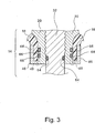
In
Der Tank
Der Tankhauptkörper
Die Armatur
Die Armatur
Eine Außenseitenabschnitt
Im Tank
In dem nach innen vorstehenden Abschnitt
Ferner wird im nach innen vorstehenden Abschnitt
Während des Einfüllens oder Entfernens eines Gases, wie eines Wasserstoffgases, in den Tank bzw. aus diesem, kommt es andererseits üblicherweise zu einer erheblichen Temperaturänderung am nach innen vorstehenden Abschnitt
Wie oben beschrieben, werden in dieser Ausführuhrungsform die Dichtungsleistung beim Abdichten der Grenzfläche zwischen der Innenumfangswand
Ferner kann der Metallring
Nun wird wieder unter Bezugnahme auf
Zuerst wird die Innenumfangswand (Harzauskleidung)
Der obere Teil der Innenumfangswand
Der untere Teil der Innenumfangswand
Ferner wird das Ventil
Nun wird eine andere bevorzugte Ausführungsform (ein Modifikationsbeispiel) der vorliegenden Erfindung beschrieben.Now, another preferred embodiment (a modification example) of the present invention will be described.
Genauer dienen der Metallring
Andere Bauteile außer dem Stützelement in dem in
Ferner weist im nach innen vorstehenden Abschnitt
Dann wird in dem in
Ferner wird in dem in
Um die Fähigkeit zu einem engen Kontakt zu verwirklichen, wird die Armatur auf solche Weise gebildet, dass der Außenumfang der Armatur
Wie oben beschrieben, werden die Armatur
Der Tank gemäß der vorliegenden Erfindung weist die oben beschriebene Zweilagenstruktur auf, die aus der Innenumfangswand
Wenn zugelassen wird, dass der Einlegering
Dagegen wird in dem in
Ferner kann der Unterschied der linearen Ausdehnung zwischen der Armatur
Ferner kann eine Verlagerung des Einlegerings
Jede der oben beschriebenen eng passenden Strukturen in Bezug auf den Einlegering
Außerdem kann ein Loch auf der Seite, wo sich der Einlegering befindet, an der Kontaktfläche zwischen dem Einlegering
Vorstehend wurden die bevorzugten Ausführungsformen der vorliegenden Erfindung beschrieben, und ein Tank gemäß diesen Ausführungsformen kann beispielsweise mit Wasserstoff, der als Brenngas verwendet wird, gefüllt werden und kann in einem Fahrzeug installiert werden, das mit einer Brennstoffzelle ausgestattet ist. Die hierin offenbarten Ausführungsformen sind nur als erläuternde Beispiele angegeben und sollten nicht als beschränkend für den Bereich der vorliegenden Erfindung aufgefasst werden.In the above, the preferred embodiments of the present invention have been described, and a tank according to these embodiments may be filled, for example, with hydrogen used as a fuel gas, and may be installed in a vehicle equipped with a fuel cell. The embodiments disclosed herein are given as illustrative examples only and should not be construed as limiting the scope of the present invention.
Claims (9)
Applications Claiming Priority (5)
| Application Number | Priority Date | Filing Date | Title |
|---|---|---|---|
| JP2005-323052 | 2005-11-08 | ||
| JP2005323052 | 2005-11-08 | ||
| JP2006-060484 | 2006-03-07 | ||
| JP2006060484A JP4935117B2 (en) | 2005-11-08 | 2006-03-07 | tank |
| PCT/JP2006/322517 WO2007055343A1 (en) | 2005-11-08 | 2006-11-07 | Tank |
Publications (2)
| Publication Number | Publication Date |
|---|---|
| DE112006003013T5 DE112006003013T5 (en) | 2008-09-25 |
| DE112006003013B4 true DE112006003013B4 (en) | 2011-07-28 |
Family
ID=38023336
Family Applications (1)
| Application Number | Title | Priority Date | Filing Date |
|---|---|---|---|
| DE112006003013T Active DE112006003013B4 (en) | 2005-11-08 | 2006-11-07 | tank |
Country Status (5)
| Country | Link |
|---|---|
| US (1) | US20090255940A1 (en) |
| JP (1) | JP4935117B2 (en) |
| CN (1) | CN101300447B (en) |
| DE (1) | DE112006003013B4 (en) |
| WO (1) | WO2007055343A1 (en) |
Cited By (25)
| Publication number | Priority date | Publication date | Assignee | Title |
|---|---|---|---|---|
| DE102014103390B4 (en) | 2013-03-14 | 2019-07-04 | GM Global Technology Operations LLC (n. d. Ges. d. Staates Delaware) | Seal assembly and the seal assembly comprising pressure vessel |
| DE102019007550A1 (en) * | 2019-10-30 | 2021-05-06 | Daimler Ag | Pressurized gas container |
| WO2021254684A1 (en) | 2020-06-17 | 2021-12-23 | Robert Bosch Gmbh | Valve device for a pressurized container, and method for producing a valve device |
| WO2022012883A1 (en) | 2020-07-15 | 2022-01-20 | Robert Bosch Gmbh | Valve seat for a pressurized container, valve device and method for producing a valve seat |
| DE102020209771A1 (en) | 2020-08-04 | 2022-02-10 | Robert Bosch Gesellschaft mit beschränkter Haftung | Valve assembly for a pressurized container and method of making a valve assembly for a pressurized container |
| DE102020213907A1 (en) | 2020-11-05 | 2022-05-05 | Robert Bosch Gesellschaft mit beschränkter Haftung | Thermal relief device for a gas tank and method of manufacturing a thermal relief device for a gas tank |
| DE102020213911A1 (en) | 2020-11-05 | 2022-05-05 | Robert Bosch Gesellschaft mit beschränkter Haftung | Tank device for a fuel cell system and method for producing a tank device for a fuel cell system |
| WO2022100902A1 (en) | 2020-11-13 | 2022-05-19 | Robert Bosch Gmbh | Pressure storage device for storing a medium, and method for operating a pressure storage device |
| DE102020214316A1 (en) | 2020-11-13 | 2022-05-19 | Robert Bosch Gesellschaft mit beschränkter Haftung | Fuel delivery device for delivering fuel for a fuel cell system, fuel cell system and method for operating a fuel delivery device for delivering fuel for a fuel cell system |
| DE102021201176A1 (en) | 2021-02-09 | 2022-08-11 | Robert Bosch Gesellschaft mit beschränkter Haftung | Tank device for storing a gaseous medium for a vehicle and method for operating a tank device for storing a gaseous medium for a vehicle |
| WO2022189296A1 (en) | 2021-03-12 | 2022-09-15 | Robert Bosch Gmbh | Measuring apparatus for determining gas permeability by a sampler, and method for operating a measuring apparatus for determining gas permeability by a sampler |
| DE102021202696A1 (en) | 2021-03-19 | 2022-09-22 | Robert Bosch Gesellschaft mit beschränkter Haftung | Tank device for storing gas fuel for a vehicle and method for operating a tank device for storing gas fuel for a vehicle |
| DE102021203429A1 (en) | 2021-04-07 | 2022-10-13 | Robert Bosch Gesellschaft mit beschränkter Haftung | Tank device for storing a gaseous medium for a vehicle, line system for supplying a vehicle with fuel and method for operating a line system and/or a tank device |
| EP4083495A1 (en) | 2021-04-29 | 2022-11-02 | Robert Bosch GmbH | Connecting device for connecting a hydrogen storage tank and a supply line for the hydrogen storage tank, hydrogen storage system and method for connecting a hydrogen storage tank with a supply line |
| DE102021204897A1 (en) | 2021-05-14 | 2022-11-17 | Robert Bosch Gesellschaft mit beschränkter Haftung | Tank valve device for at least one tank container, tank device for storing a fuel and method for operating a tank device |
| DE102021205557A1 (en) | 2021-06-01 | 2022-12-01 | Robert Bosch Gesellschaft mit beschränkter Haftung | Recirculation device for hydrogen supply in a fuel cell and method for operating a recirculation device for hydrogen supply in a fuel cell |
| DE102021205566A1 (en) | 2021-06-01 | 2022-12-01 | Robert Bosch Gesellschaft mit beschränkter Haftung | Control device for hydrogen supply in a fuel cell, fuel cell device and method for operating a control device for hydrogen supply in a fuel cell |
| WO2022263156A1 (en) | 2021-06-18 | 2022-12-22 | Robert Bosch Gmbh | Tank valve device for at least one tank container, tank apparatus for a fuel, and method for operating a tank apparatus for a fuel |
| WO2023285119A1 (en) | 2021-07-14 | 2023-01-19 | Robert Bosch Gmbh | Fuel delivery apparatus for delivering a fuel for a fuel cell system and method for operating a fuel delivery apparatus for delivering a fuel for a fuel cell system |
| WO2023051987A1 (en) | 2021-10-01 | 2023-04-06 | Robert Bosch Gmbh | Refuelling device for a vehicle powered by hydrogen or a gaseous fuel, and method for operating a refuelling device for a vehicle powered by hydrogen or a gaseous fuel |
| DE102021211060A1 (en) | 2021-10-01 | 2023-04-06 | Robert Bosch Gesellschaft mit beschränkter Haftung | Fan device for a hydrogen circuit in a fuel cell device and method for operating a fan device |
| DE102021214838A1 (en) | 2021-12-21 | 2023-06-22 | Robert Bosch Gesellschaft mit beschränkter Haftung | Compressor device for a hydrogen feed and method of manufacturing a compressor device for a hydrogen feed |
| DE102022200233A1 (en) | 2022-01-12 | 2023-07-13 | Robert Bosch Gesellschaft mit beschränkter Haftung | Metering device for a hydrogen circuit for a fuel cell device and method for operating a metering device for a hydrogen circuit for a fuel cell device |
| WO2023135121A2 (en) | 2022-01-14 | 2023-07-20 | Robert Bosch Gmbh | Method for operating a fuel cell device, and fuel cell device |
| DE102022208131A1 (en) | 2022-08-04 | 2024-02-15 | Mahle International Gmbh | pressure vessel |
Families Citing this family (42)
| Publication number | Priority date | Publication date | Assignee | Title |
|---|---|---|---|---|
| JP4875915B2 (en) * | 2006-03-29 | 2012-02-15 | 富士重工業株式会社 | Pressure vessel |
| JP4457359B2 (en) * | 2006-12-13 | 2010-04-28 | トヨタ自動車株式会社 | Pressure vessel |
| JP5018100B2 (en) * | 2007-01-22 | 2012-09-05 | トヨタ自動車株式会社 | Pressure vessel and pressure vessel manufacturing method |
| JP5169473B2 (en) * | 2008-05-19 | 2013-03-27 | 株式会社ジェイテクト | Fluid supply valve assembly device |
| US20100124688A1 (en) * | 2008-11-18 | 2010-05-20 | Eveready Battery Company, Inc. | Regulator Valve for a Fluid Consuming Battery |
| JP5375296B2 (en) * | 2009-04-16 | 2013-12-25 | トヨタ自動車株式会社 | Hydrogen tank |
| JP5471143B2 (en) * | 2009-08-07 | 2014-04-16 | スズキ株式会社 | High pressure gas tank system |
| JP5083289B2 (en) * | 2009-10-19 | 2012-11-28 | トヨタ自動車株式会社 | Tank and tank manufacturing method |
| DE102009049948B4 (en) * | 2009-10-19 | 2012-02-02 | Kautex Maschinenbau Gmbh | pressure vessel |
| US8523002B2 (en) * | 2010-02-26 | 2013-09-03 | GM Global Technology Operations LLC | Embedded reinforcement sleeve for a pressure vessel |
| WO2011103688A1 (en) * | 2010-02-26 | 2011-09-01 | Dynetek Industries Ltd. | Anti-extrusion sealing system for the outlet of a plastic-lined compressed gas cylinder |
| DE102010018700B4 (en) * | 2010-04-29 | 2019-05-09 | Magna Steyr Fahrzeugtechnik Ag & Co. Kg | pressure vessel |
| US8863977B2 (en) * | 2010-11-30 | 2014-10-21 | Advanced Lightweight Engineering B.V. | Vessel with rotationally free base flange |
| JP5869362B2 (en) * | 2012-02-15 | 2016-02-24 | 高圧ガス保安協会 | Pressure vessel unit |
| JP5904081B2 (en) | 2012-10-05 | 2016-04-13 | トヨタ自動車株式会社 | Pressure vessel and production method thereof |
| US9316357B2 (en) * | 2012-11-23 | 2016-04-19 | ILJIN Composites Co., Ltd. | Pressure vessel |
| US8978920B2 (en) * | 2013-03-14 | 2015-03-17 | GM Global Technology Operations LLC | Sealing assemblies and pressurized fluid vessels including the sealing assemblies |
| JP6235797B2 (en) * | 2013-06-06 | 2017-11-22 | 八千代工業株式会社 | Pressure vessel |
| US8881932B1 (en) * | 2013-06-25 | 2014-11-11 | Quantum Fuel Systems Technology Worldwide, Inc. | Adapterless closure assembly for composite pressure vessels |
| MX2017000709A (en) * | 2014-07-17 | 2017-10-16 | Faber Ind Spa | Pressure vessel. |
| USD746942S1 (en) | 2014-10-21 | 2016-01-05 | Advanced Lightweight Engineering B.V. | Low weight pressure vessel |
| JP6601379B2 (en) * | 2016-12-06 | 2019-11-06 | トヨタ自動車株式会社 | Pressure vessel and method for manufacturing pressure vessel |
| KR102463415B1 (en) * | 2016-12-20 | 2022-11-03 | 현대자동차주식회사 | High pressure tank having reinforced boss-part |
| JP6597668B2 (en) * | 2017-02-23 | 2019-10-30 | トヨタ自動車株式会社 | Pressure vessel |
| DE102017204710A1 (en) | 2017-03-21 | 2018-09-27 | Volkswagen Aktiengesellschaft | Container for storing a fluid medium and vehicle with such a container |
| DE102017204713A1 (en) | 2017-03-21 | 2018-09-27 | Volkswagen Aktiengesellschaft | Container for storing a fluid medium and vehicle with such a container |
| DE102017204707A1 (en) | 2017-03-21 | 2018-09-27 | Volkswagen Aktiengesellschaft | Container for storing a fluid medium and vehicle with such a container |
| EP3625495A1 (en) | 2017-05-15 | 2020-03-25 | Advanced Lightweight Engineering B.V. | Pressure vessel for the storage of pressurized fluids and vehicle comprising such a pressure vessel |
| US10753474B2 (en) * | 2017-11-07 | 2020-08-25 | Hexagon Technology As | Blind boss fitting with redundant seal |
| JP7311243B2 (en) * | 2017-12-28 | 2023-07-19 | トヨタ自動車株式会社 | High pressure tank with protector |
| CN108131555B (en) * | 2017-12-31 | 2023-07-25 | 亚普汽车部件股份有限公司 | High-pressure composite container with sealing structure |
| FR3089160B1 (en) | 2018-11-30 | 2020-12-04 | Plastic Omnium Advanced Innovation & Res | Internal casing for pressurized fluid storage tank for motor vehicle |
| DE102019210515A1 (en) * | 2019-07-17 | 2021-01-21 | Robert Bosch Gmbh | Tank device for storing a gaseous medium |
| FR3102530B1 (en) * | 2019-10-24 | 2023-09-01 | Faurecia Systemes Dechappement | Pressurized gas tank |
| FR3106192B1 (en) * | 2020-01-15 | 2023-11-24 | Faurecia Systemes Dechappement | Tank, particularly for hydrogen, with improved sealing |
| EP3919805B1 (en) * | 2020-06-05 | 2023-11-29 | Magna Energy Storage Systems GesmbH | High pressure vessel |
| CN111649226A (en) * | 2020-06-15 | 2020-09-11 | 安徽绿动能源有限公司 | Plastic liner fiber fully-wound gas cylinder and manufacturing method thereof |
| CN111963888B (en) * | 2020-08-28 | 2022-11-04 | 亚普汽车部件股份有限公司 | Sealing structure of high-pressure gas cylinder with plastic inner container |
| CN112833329A (en) * | 2021-01-27 | 2021-05-25 | 中材科技(苏州)有限公司 | Bottle mouth structure for nonmetal liner fiber reinforced high-pressure gas bottle |
| DE102021107165B4 (en) | 2021-03-23 | 2023-08-24 | Worthington Cylinders Gmbh | Final boss seal |
| US11732843B2 (en) * | 2021-07-19 | 2023-08-22 | Caterpillar Inc. | On-tank regulator for high-pressure tank |
| KR20230096211A (en) * | 2021-12-22 | 2023-06-30 | 일진하이솔루스 주식회사 | Manufacturing Methods of Integral Type Sealing Gasket For High Pressure Vessel |
Citations (13)
| Publication number | Priority date | Publication date | Assignee | Title |
|---|---|---|---|---|
| EP0203631A2 (en) * | 1985-05-30 | 1986-12-03 | Duktrad International | Annular closure with a flange for a pressurized vessel made of synthetic material |
| JPS62255698A (en) * | 1986-04-25 | 1987-11-07 | Agency Of Ind Science & Technol | Attaching of accessary to container made of composite material |
| JPH08219387A (en) * | 1995-02-15 | 1996-08-30 | Toray Ind Inc | Gas cylinder |
| US5817203A (en) * | 1992-07-06 | 1998-10-06 | Edo Corporation, Fiber Science Division | Method of forming reusable seamless mandrels for the fabrication of hollow fiber wound vessels |
| JPH1113995A (en) * | 1997-06-23 | 1999-01-22 | Kobe Steel Ltd | Socket structure of pressure container of plastic liner frp(fiber reinforced plastics) |
| DE69624348T2 (en) * | 1996-01-17 | 2003-06-26 | Fybrasynthetica Do Brasil Ltda | A PLASTIC CONTAINER FOR PRESSURIZED FLUIDS |
| JP2003247696A (en) | 2002-02-22 | 2003-09-05 | Aisan Ind Co Ltd | High-pressure tank |
| DE102004003319A1 (en) * | 2003-01-24 | 2004-08-26 | Kabushiki Kaisha Toyota Jidoshokki, Kariya | High-pressure tank for storing high-pressure hydrogen for vehicle fuel cells, has deformable casing or cover section that aligns one sealing surface with another when deformed by pressure in casing |
| DE10360953A1 (en) * | 2002-12-27 | 2004-11-11 | Toyoda Gosei Co., Ltd., Nishikasugai | pressure vessel |
| US20050006393A1 (en) * | 2003-07-08 | 2005-01-13 | Polymer & Steel Technologies Holding Company, L.L.C. | Filament-reinforced composite thermoplastic pressure vessel fitting assembly and method |
| JP2005048918A (en) * | 2003-07-31 | 2005-02-24 | Toyota Motor Corp | Tank |
| DE10329990B3 (en) * | 2003-07-02 | 2005-04-21 | Benteler Automobiltechnik Gmbh | Pressure gas tank |
| CA2559452A1 (en) * | 2004-03-11 | 2005-10-06 | Korea Composite Research Co., Ltd. | The high gas-tighten metallic nozzle-boss for the high pressure composite vessel |
Family Cites Families (29)
| Publication number | Priority date | Publication date | Assignee | Title |
|---|---|---|---|---|
| US3182110A (en) * | 1958-11-05 | 1965-05-04 | White Consolidated Ind Inc | Method and apparatus for making fiber glass tank |
| US3137405A (en) * | 1961-12-18 | 1964-06-16 | North American Aviation Inc | Pressure vessel |
| US3419180A (en) * | 1966-12-07 | 1968-12-31 | Halliburton Co | Closure assembly for high-pressure, high-temperature vessels |
| US3917115A (en) * | 1974-03-15 | 1975-11-04 | Amf Inc | Diving cylinder with liner |
| US4537329A (en) * | 1984-04-02 | 1985-08-27 | Culligan International Company | Tank lining system |
| US5429845A (en) * | 1992-01-10 | 1995-07-04 | Brunswick Corporation | Boss for a filament wound pressure vessel |
| US5494188A (en) * | 1992-01-28 | 1996-02-27 | Edo Canada Ltd. | Fluid pressure vessel boss-liner attachment system with liner/exterior mechanism direct coupling |
| US5253778A (en) * | 1992-01-28 | 1993-10-19 | Edo Canada Ltd. | Fluid pressure vessel boss-liner attachment system |
| US5287988A (en) * | 1993-02-03 | 1994-02-22 | Brunswick Corporation | Metal-lined pressure vessel |
| US5476189A (en) * | 1993-12-03 | 1995-12-19 | Duvall; Paul F. | Pressure vessel with damage mitigating system |
| US5518141A (en) * | 1994-01-24 | 1996-05-21 | Newhouse; Norman L. | Pressure vessel with system to prevent liner separation |
| US5388720A (en) * | 1994-04-15 | 1995-02-14 | Essef Corporation | Flanged diffuser and air cell retainer for pressure vessel |
| EP0810081B1 (en) * | 1995-12-04 | 2003-03-26 | Toray Industries, Inc. | Pressure vessel and method of manufacturing same |
| US5568878A (en) * | 1996-01-11 | 1996-10-29 | Essef Corporation | Filament wound pressure vessel having a reinforced access opening |
| US6089399A (en) * | 1997-01-14 | 2000-07-18 | Chatwins Group, Inc. | Inert-metal lined, seamless steel-body cylinder |
| US5938209A (en) * | 1997-02-14 | 1999-08-17 | Alternative Fuel Systems, Inc. | Seal system for fluid pressure vessels |
| DE19751411C1 (en) * | 1997-11-14 | 1999-01-14 | Mannesmann Ag | Composite fibre-reinforced pressurised gas tank including liner with end neck sections |
| US5979692A (en) * | 1998-03-13 | 1999-11-09 | Harsco Corporation | Boss for composite pressure vessel having polymeric liner |
| US6135308A (en) * | 1998-06-26 | 2000-10-24 | Industrial Technology Research Institute | Boss for a filament wound pressure vessel |
| EP1151224B1 (en) * | 1999-02-16 | 2004-04-21 | Alliant Techsystems Inc. | Closure assembly for lined tanks, and vehicles equipped with the same |
| JP3523802B2 (en) * | 1999-04-07 | 2004-04-26 | 豊田合成株式会社 | Pressure vessel |
| DE10000705A1 (en) * | 2000-01-10 | 2001-07-19 | Ralph Funck | Pressure container for storing liquid and / or gaseous media under pressure consisting of a plastic core container which is reinforced with fiber-reinforced plastics and process for its production |
| US7032768B2 (en) * | 2002-04-04 | 2006-04-25 | Felbaum John W | Inert-metal lined steel-bodied vessel end-closure device |
| JP4219194B2 (en) * | 2003-03-11 | 2009-02-04 | 株式会社豊田自動織機 | Pressure vessel |
| JP4525021B2 (en) * | 2003-07-31 | 2010-08-18 | トヨタ自動車株式会社 | tank |
| JP4715841B2 (en) * | 2005-02-02 | 2011-07-06 | トヨタ自動車株式会社 | High pressure tank seal structure |
| CN100575766C (en) * | 2005-06-06 | 2009-12-30 | 丰田自动车株式会社 | The manufacture method of pressurized container |
| US7731051B2 (en) * | 2005-07-13 | 2010-06-08 | Gm Global Technology Operations, Inc. | Hydrogen pressure tank including an inner liner with an outer annular flange |
| US7556171B2 (en) * | 2005-11-17 | 2009-07-07 | Toyota Jidosha Kabushiki Kaisha | Tank |
-
2006
- 2006-03-07 JP JP2006060484A patent/JP4935117B2/en active Active
- 2006-11-07 DE DE112006003013T patent/DE112006003013B4/en active Active
- 2006-11-07 CN CN2006800405942A patent/CN101300447B/en active Active
- 2006-11-07 US US11/992,957 patent/US20090255940A1/en not_active Abandoned
- 2006-11-07 WO PCT/JP2006/322517 patent/WO2007055343A1/en active Application Filing
Patent Citations (13)
| Publication number | Priority date | Publication date | Assignee | Title |
|---|---|---|---|---|
| EP0203631A2 (en) * | 1985-05-30 | 1986-12-03 | Duktrad International | Annular closure with a flange for a pressurized vessel made of synthetic material |
| JPS62255698A (en) * | 1986-04-25 | 1987-11-07 | Agency Of Ind Science & Technol | Attaching of accessary to container made of composite material |
| US5817203A (en) * | 1992-07-06 | 1998-10-06 | Edo Corporation, Fiber Science Division | Method of forming reusable seamless mandrels for the fabrication of hollow fiber wound vessels |
| JPH08219387A (en) * | 1995-02-15 | 1996-08-30 | Toray Ind Inc | Gas cylinder |
| DE69624348T2 (en) * | 1996-01-17 | 2003-06-26 | Fybrasynthetica Do Brasil Ltda | A PLASTIC CONTAINER FOR PRESSURIZED FLUIDS |
| JPH1113995A (en) * | 1997-06-23 | 1999-01-22 | Kobe Steel Ltd | Socket structure of pressure container of plastic liner frp(fiber reinforced plastics) |
| JP2003247696A (en) | 2002-02-22 | 2003-09-05 | Aisan Ind Co Ltd | High-pressure tank |
| DE10360953A1 (en) * | 2002-12-27 | 2004-11-11 | Toyoda Gosei Co., Ltd., Nishikasugai | pressure vessel |
| DE102004003319A1 (en) * | 2003-01-24 | 2004-08-26 | Kabushiki Kaisha Toyota Jidoshokki, Kariya | High-pressure tank for storing high-pressure hydrogen for vehicle fuel cells, has deformable casing or cover section that aligns one sealing surface with another when deformed by pressure in casing |
| DE10329990B3 (en) * | 2003-07-02 | 2005-04-21 | Benteler Automobiltechnik Gmbh | Pressure gas tank |
| US20050006393A1 (en) * | 2003-07-08 | 2005-01-13 | Polymer & Steel Technologies Holding Company, L.L.C. | Filament-reinforced composite thermoplastic pressure vessel fitting assembly and method |
| JP2005048918A (en) * | 2003-07-31 | 2005-02-24 | Toyota Motor Corp | Tank |
| CA2559452A1 (en) * | 2004-03-11 | 2005-10-06 | Korea Composite Research Co., Ltd. | The high gas-tighten metallic nozzle-boss for the high pressure composite vessel |
Cited By (39)
| Publication number | Priority date | Publication date | Assignee | Title |
|---|---|---|---|---|
| DE102014103390B4 (en) | 2013-03-14 | 2019-07-04 | GM Global Technology Operations LLC (n. d. Ges. d. Staates Delaware) | Seal assembly and the seal assembly comprising pressure vessel |
| DE102019007550A1 (en) * | 2019-10-30 | 2021-05-06 | Daimler Ag | Pressurized gas container |
| WO2021254684A1 (en) | 2020-06-17 | 2021-12-23 | Robert Bosch Gmbh | Valve device for a pressurized container, and method for producing a valve device |
| DE102020207501A1 (en) | 2020-06-17 | 2021-12-23 | Robert Bosch Gesellschaft mit beschränkter Haftung | Valve device for a pressurized container and method of making a valve device |
| WO2022012883A1 (en) | 2020-07-15 | 2022-01-20 | Robert Bosch Gmbh | Valve seat for a pressurized container, valve device and method for producing a valve seat |
| DE102020208843A1 (en) | 2020-07-15 | 2022-01-20 | Robert Bosch Gesellschaft mit beschränkter Haftung | Valve socket for a pressurized container, valve device and method of manufacturing a valve socket |
| DE102020209771A1 (en) | 2020-08-04 | 2022-02-10 | Robert Bosch Gesellschaft mit beschränkter Haftung | Valve assembly for a pressurized container and method of making a valve assembly for a pressurized container |
| DE102020213907A1 (en) | 2020-11-05 | 2022-05-05 | Robert Bosch Gesellschaft mit beschränkter Haftung | Thermal relief device for a gas tank and method of manufacturing a thermal relief device for a gas tank |
| DE102020213911A1 (en) | 2020-11-05 | 2022-05-05 | Robert Bosch Gesellschaft mit beschränkter Haftung | Tank device for a fuel cell system and method for producing a tank device for a fuel cell system |
| WO2022096265A1 (en) | 2020-11-05 | 2022-05-12 | Robert Bosch Gmbh | Tank device for a fuel cell system and method for producing a tank device for a fuel cell system |
| WO2022096267A1 (en) | 2020-11-05 | 2022-05-12 | Robert Bosch Gmbh | Thermal relief device for a gas tank, and method for producing a thermal relief device for a gas tank |
| WO2022100902A1 (en) | 2020-11-13 | 2022-05-19 | Robert Bosch Gmbh | Pressure storage device for storing a medium, and method for operating a pressure storage device |
| DE102020214316A1 (en) | 2020-11-13 | 2022-05-19 | Robert Bosch Gesellschaft mit beschränkter Haftung | Fuel delivery device for delivering fuel for a fuel cell system, fuel cell system and method for operating a fuel delivery device for delivering fuel for a fuel cell system |
| DE102020212078A1 (en) | 2020-11-13 | 2022-05-19 | Robert Bosch Gesellschaft mit beschränkter Haftung | Pressure storage device for storing a medium and method for operating a pressure storage device |
| WO2022100978A1 (en) | 2020-11-13 | 2022-05-19 | Robert Bosch Gmbh | Fuel conveying device for conveying a fuel for a fuel cell system, fuel cell system and method for operating a fuel conveying device for conveying a fuel for a fuel cell system |
| DE102021201176A1 (en) | 2021-02-09 | 2022-08-11 | Robert Bosch Gesellschaft mit beschränkter Haftung | Tank device for storing a gaseous medium for a vehicle and method for operating a tank device for storing a gaseous medium for a vehicle |
| WO2022171351A1 (en) | 2021-02-09 | 2022-08-18 | Robert Bosch Gmbh | Tank apparatus for storing a gaseous medium for a motor vehicle and method for operating a tank apparatus for storing a gaseous medium for a vehicle |
| WO2022189296A1 (en) | 2021-03-12 | 2022-09-15 | Robert Bosch Gmbh | Measuring apparatus for determining gas permeability by a sampler, and method for operating a measuring apparatus for determining gas permeability by a sampler |
| DE102021202413A1 (en) | 2021-03-12 | 2022-09-15 | Robert Bosch Gesellschaft mit beschränkter Haftung | Measuring device for determining gas permeability through a sample and method for operating a measuring device for determining gas permeability through a sample |
| DE102021202696A1 (en) | 2021-03-19 | 2022-09-22 | Robert Bosch Gesellschaft mit beschränkter Haftung | Tank device for storing gas fuel for a vehicle and method for operating a tank device for storing gas fuel for a vehicle |
| WO2022194474A1 (en) | 2021-03-19 | 2022-09-22 | Robert Bosch Gmbh | Tank device for storing a gaseous medium for a motor vehicle and method for operating a tank device for storing a gaseous medium for a vehicle |
| DE102021203429A1 (en) | 2021-04-07 | 2022-10-13 | Robert Bosch Gesellschaft mit beschränkter Haftung | Tank device for storing a gaseous medium for a vehicle, line system for supplying a vehicle with fuel and method for operating a line system and/or a tank device |
| EP4083495A1 (en) | 2021-04-29 | 2022-11-02 | Robert Bosch GmbH | Connecting device for connecting a hydrogen storage tank and a supply line for the hydrogen storage tank, hydrogen storage system and method for connecting a hydrogen storage tank with a supply line |
| WO2022228917A1 (en) | 2021-04-29 | 2022-11-03 | Robert Bosch Gmbh | Connecting device for connecting a hydrogen tank vessel and a feed line for the hydrogen tank vessel, hydrogen storage system, and method for connecting a hydrogen tank vessel to a feed line |
| DE102021204897A1 (en) | 2021-05-14 | 2022-11-17 | Robert Bosch Gesellschaft mit beschränkter Haftung | Tank valve device for at least one tank container, tank device for storing a fuel and method for operating a tank device |
| DE102021205557A1 (en) | 2021-06-01 | 2022-12-01 | Robert Bosch Gesellschaft mit beschränkter Haftung | Recirculation device for hydrogen supply in a fuel cell and method for operating a recirculation device for hydrogen supply in a fuel cell |
| DE102021205566A1 (en) | 2021-06-01 | 2022-12-01 | Robert Bosch Gesellschaft mit beschränkter Haftung | Control device for hydrogen supply in a fuel cell, fuel cell device and method for operating a control device for hydrogen supply in a fuel cell |
| WO2022263156A1 (en) | 2021-06-18 | 2022-12-22 | Robert Bosch Gmbh | Tank valve device for at least one tank container, tank apparatus for a fuel, and method for operating a tank apparatus for a fuel |
| DE102021206257A1 (en) | 2021-06-18 | 2022-12-22 | Robert Bosch Gesellschaft mit beschränkter Haftung | Tank valve device for at least one tank container, tank device for a fuel and method for operating a tank device for a fuel |
| WO2023285119A1 (en) | 2021-07-14 | 2023-01-19 | Robert Bosch Gmbh | Fuel delivery apparatus for delivering a fuel for a fuel cell system and method for operating a fuel delivery apparatus for delivering a fuel for a fuel cell system |
| DE102021207487A1 (en) | 2021-07-14 | 2023-01-19 | Robert Bosch Gesellschaft mit beschränkter Haftung | Fuel delivery device for delivering a fuel for a fuel cell system and method for operating a fuel delivery device for delivering a fuel for a fuel cell system |
| WO2023051987A1 (en) | 2021-10-01 | 2023-04-06 | Robert Bosch Gmbh | Refuelling device for a vehicle powered by hydrogen or a gaseous fuel, and method for operating a refuelling device for a vehicle powered by hydrogen or a gaseous fuel |
| DE102021211085A1 (en) | 2021-10-01 | 2023-04-06 | Robert Bosch Gesellschaft mit beschränkter Haftung | Refueling device for a vehicle powered by hydrogen or a gaseous fuel and method for operating a refueling device for a vehicle powered by hydrogen or a gaseous fuel |
| DE102021211060A1 (en) | 2021-10-01 | 2023-04-06 | Robert Bosch Gesellschaft mit beschränkter Haftung | Fan device for a hydrogen circuit in a fuel cell device and method for operating a fan device |
| DE102021214838A1 (en) | 2021-12-21 | 2023-06-22 | Robert Bosch Gesellschaft mit beschränkter Haftung | Compressor device for a hydrogen feed and method of manufacturing a compressor device for a hydrogen feed |
| DE102022200233A1 (en) | 2022-01-12 | 2023-07-13 | Robert Bosch Gesellschaft mit beschränkter Haftung | Metering device for a hydrogen circuit for a fuel cell device and method for operating a metering device for a hydrogen circuit for a fuel cell device |
| WO2023135121A2 (en) | 2022-01-14 | 2023-07-20 | Robert Bosch Gmbh | Method for operating a fuel cell device, and fuel cell device |
| DE102022200368A1 (en) | 2022-01-14 | 2023-07-20 | Robert Bosch Gesellschaft mit beschränkter Haftung | Method for operating a fuel cell device and fuel cell device |
| DE102022208131A1 (en) | 2022-08-04 | 2024-02-15 | Mahle International Gmbh | pressure vessel |
Also Published As
| Publication number | Publication date |
|---|---|
| WO2007055343A1 (en) | 2007-05-18 |
| US20090255940A1 (en) | 2009-10-15 |
| CN101300447A (en) | 2008-11-05 |
| CN101300447B (en) | 2011-05-11 |
| DE112006003013T5 (en) | 2008-09-25 |
| JP2007155116A (en) | 2007-06-21 |
| JP4935117B2 (en) | 2012-05-23 |
Similar Documents
| Publication | Publication Date | Title |
|---|---|---|
| DE112006003013B4 (en) | tank | |
| EP3366975B1 (en) | Pole cap with pressure connection element for pressure vessels | |
| DE102006031118B4 (en) | Hydrogen pressure tank | |
| EP2718570B1 (en) | Pressure vessel | |
| DE102010018700A1 (en) | pressure vessel | |
| DE602004011371T2 (en) | ball joint | |
| DE2144957A1 (en) | Hydraulic coupling with metallic sealing elements | |
| DE102006001052A1 (en) | Pressure container for storing fluid or gaseous medium, has gap formed between collar and core container, and filled with buffer ring that has outer contour connecting contiguous outer contours of core container and collar | |
| DE3405780A1 (en) | FLUID SEAL | |
| DE3317061A1 (en) | FLANGE JOINT ARRANGEMENT | |
| DE60313221T2 (en) | MOUNTING STRUCTURE FOR COVERING A RESIN RESERVOIR | |
| EP0737558A1 (en) | Method for producing a ball joint and associated lining | |
| DE102015100035A1 (en) | Mouthpiece construction for a pressure vessel | |
| DE102016206863A1 (en) | Axial ball joint and adjustable length two-point link with such an axial ball joint | |
| EP2478234B1 (en) | Joint with a ball fixed to a ball stud and a slide bearing foil for said joint | |
| DE102015007743A1 (en) | Thrust bearing and pneumatic shock absorber | |
| DE2451084A1 (en) | BALL JOINT | |
| DE112011102044T5 (en) | Improved snap-in center seal bush | |
| EP1240438B1 (en) | Ball joint | |
| EP2184822B1 (en) | Submersible motor | |
| DE4102371A1 (en) | SEALING SLEEVE | |
| DE102011120041A1 (en) | Pressure tank for motor vehicle, for storing fluid medium, has sealing portion that is formed between wall section of base surface and mounting flange portions connected with connecting terminal structure to form one-piece portion | |
| DE102017215191A1 (en) | Pressure vessel for storing liquid and / or gaseous media | |
| DE102006013046A1 (en) | Joint or bearing arrangement has joint pin, head region movable in relation to receiving joint cup, and through opening that is left in region of housing receiving joint cup | |
| DE4420489C2 (en) | Ball joint |
Legal Events
| Date | Code | Title | Description |
|---|---|---|---|
| OP8 | Request for examination as to paragraph 44 patent law | ||
| R018 | Grant decision by examination section/examining division | ||
| R020 | Patent grant now final |
Effective date: 20111029 |
|
| R084 | Declaration of willingness to licence |