DE112010000981T5 - Optical scanning and imaging systems based on dual-pulse laser systems - Google Patents
Optical scanning and imaging systems based on dual-pulse laser systems Download PDFInfo
- Publication number
- DE112010000981T5 DE112010000981T5 DE112010000981T DE112010000981T DE112010000981T5 DE 112010000981 T5 DE112010000981 T5 DE 112010000981T5 DE 112010000981 T DE112010000981 T DE 112010000981T DE 112010000981 T DE112010000981 T DE 112010000981T DE 112010000981 T5 DE112010000981 T5 DE 112010000981T5
- Authority
- DE
- Germany
- Prior art keywords
- frequency
- oscillators
- fiber
- optical
- laser system
- Prior art date
- Legal status (The legal status is an assumption and is not a legal conclusion. Google has not performed a legal analysis and makes no representation as to the accuracy of the status listed.)
- Withdrawn
Links
Images


Classifications
-
- G—PHYSICS
- G01—MEASURING; TESTING
- G01N—INVESTIGATING OR ANALYSING MATERIALS BY DETERMINING THEIR CHEMICAL OR PHYSICAL PROPERTIES
- G01N21/00—Investigating or analysing materials by the use of optical means, i.e. using sub-millimetre waves, infrared, visible or ultraviolet light
- G01N21/17—Systems in which incident light is modified in accordance with the properties of the material investigated
- G01N21/25—Colour; Spectral properties, i.e. comparison of effect of material on the light at two or more different wavelengths or wavelength bands
- G01N21/31—Investigating relative effect of material at wavelengths characteristic of specific elements or molecules, e.g. atomic absorption spectrometry
-
- G—PHYSICS
- G01—MEASURING; TESTING
- G01B—MEASURING LENGTH, THICKNESS OR SIMILAR LINEAR DIMENSIONS; MEASURING ANGLES; MEASURING AREAS; MEASURING IRREGULARITIES OF SURFACES OR CONTOURS
- G01B9/00—Measuring instruments characterised by the use of optical techniques
- G01B9/02—Interferometers
- G01B9/02001—Interferometers characterised by controlling or generating intrinsic radiation properties
-
- H—ELECTRICITY
- H01—ELECTRIC ELEMENTS
- H01S—DEVICES USING THE PROCESS OF LIGHT AMPLIFICATION BY STIMULATED EMISSION OF RADIATION [LASER] TO AMPLIFY OR GENERATE LIGHT; DEVICES USING STIMULATED EMISSION OF ELECTROMAGNETIC RADIATION IN WAVE RANGES OTHER THAN OPTICAL
- H01S3/00—Lasers, i.e. devices using stimulated emission of electromagnetic radiation in the infrared, visible or ultraviolet wave range
- H01S3/10—Controlling the intensity, frequency, phase, polarisation or direction of the emitted radiation, e.g. switching, gating, modulating or demodulating
- H01S3/10038—Amplitude control
- H01S3/10046—Pulse repetition rate control
-
- H—ELECTRICITY
- H01—ELECTRIC ELEMENTS
- H01S—DEVICES USING THE PROCESS OF LIGHT AMPLIFICATION BY STIMULATED EMISSION OF RADIATION [LASER] TO AMPLIFY OR GENERATE LIGHT; DEVICES USING STIMULATED EMISSION OF ELECTROMAGNETIC RADIATION IN WAVE RANGES OTHER THAN OPTICAL
- H01S3/00—Lasers, i.e. devices using stimulated emission of electromagnetic radiation in the infrared, visible or ultraviolet wave range
- H01S3/10—Controlling the intensity, frequency, phase, polarisation or direction of the emitted radiation, e.g. switching, gating, modulating or demodulating
- H01S3/106—Controlling the intensity, frequency, phase, polarisation or direction of the emitted radiation, e.g. switching, gating, modulating or demodulating by controlling devices placed within the cavity
- H01S3/1068—Controlling the intensity, frequency, phase, polarisation or direction of the emitted radiation, e.g. switching, gating, modulating or demodulating by controlling devices placed within the cavity using an acousto-optical device
-
- H—ELECTRICITY
- H01—ELECTRIC ELEMENTS
- H01S—DEVICES USING THE PROCESS OF LIGHT AMPLIFICATION BY STIMULATED EMISSION OF RADIATION [LASER] TO AMPLIFY OR GENERATE LIGHT; DEVICES USING STIMULATED EMISSION OF ELECTROMAGNETIC RADIATION IN WAVE RANGES OTHER THAN OPTICAL
- H01S3/00—Lasers, i.e. devices using stimulated emission of electromagnetic radiation in the infrared, visible or ultraviolet wave range
- H01S3/10—Controlling the intensity, frequency, phase, polarisation or direction of the emitted radiation, e.g. switching, gating, modulating or demodulating
- H01S3/11—Mode locking; Q-switching; Other giant-pulse techniques, e.g. cavity dumping
- H01S3/1106—Mode locking
- H01S3/1112—Passive mode locking
- H01S3/1115—Passive mode locking using intracavity saturable absorbers
-
- H—ELECTRICITY
- H01—ELECTRIC ELEMENTS
- H01S—DEVICES USING THE PROCESS OF LIGHT AMPLIFICATION BY STIMULATED EMISSION OF RADIATION [LASER] TO AMPLIFY OR GENERATE LIGHT; DEVICES USING STIMULATED EMISSION OF ELECTROMAGNETIC RADIATION IN WAVE RANGES OTHER THAN OPTICAL
- H01S3/00—Lasers, i.e. devices using stimulated emission of electromagnetic radiation in the infrared, visible or ultraviolet wave range
- H01S3/10—Controlling the intensity, frequency, phase, polarisation or direction of the emitted radiation, e.g. switching, gating, modulating or demodulating
- H01S3/13—Stabilisation of laser output parameters, e.g. frequency or amplitude
-
- H—ELECTRICITY
- H01—ELECTRIC ELEMENTS
- H01S—DEVICES USING THE PROCESS OF LIGHT AMPLIFICATION BY STIMULATED EMISSION OF RADIATION [LASER] TO AMPLIFY OR GENERATE LIGHT; DEVICES USING STIMULATED EMISSION OF ELECTROMAGNETIC RADIATION IN WAVE RANGES OTHER THAN OPTICAL
- H01S3/00—Lasers, i.e. devices using stimulated emission of electromagnetic radiation in the infrared, visible or ultraviolet wave range
- H01S3/23—Arrangements of two or more lasers not provided for in groups H01S3/02 - H01S3/22, e.g. tandem arrangements of separate active media
- H01S3/2383—Parallel arrangements
-
- G—PHYSICS
- G01—MEASURING; TESTING
- G01N—INVESTIGATING OR ANALYSING MATERIALS BY DETERMINING THEIR CHEMICAL OR PHYSICAL PROPERTIES
- G01N21/00—Investigating or analysing materials by the use of optical means, i.e. using sub-millimetre waves, infrared, visible or ultraviolet light
- G01N21/17—Systems in which incident light is modified in accordance with the properties of the material investigated
- G01N21/25—Colour; Spectral properties, i.e. comparison of effect of material on the light at two or more different wavelengths or wavelength bands
- G01N21/31—Investigating relative effect of material at wavelengths characteristic of specific elements or molecules, e.g. atomic absorption spectrometry
- G01N21/314—Investigating relative effect of material at wavelengths characteristic of specific elements or molecules, e.g. atomic absorption spectrometry with comparison of measurements at specific and non-specific wavelengths
- G01N2021/317—Special constructive features
-
- G—PHYSICS
- G02—OPTICS
- G02B—OPTICAL ELEMENTS, SYSTEMS OR APPARATUS
- G02B6/00—Light guides; Structural details of arrangements comprising light guides and other optical elements, e.g. couplings
- G02B6/02—Optical fibres with cladding with or without a coating
- G02B6/02295—Microstructured optical fibre
- G02B6/023—Microstructured optical fibre having different index layers arranged around the core for guiding light by reflection, i.e. 1D crystal, e.g. omniguide
- G02B6/02304—Core having lower refractive index than cladding, e.g. air filled, hollow core
-
- H—ELECTRICITY
- H01—ELECTRIC ELEMENTS
- H01S—DEVICES USING THE PROCESS OF LIGHT AMPLIFICATION BY STIMULATED EMISSION OF RADIATION [LASER] TO AMPLIFY OR GENERATE LIGHT; DEVICES USING STIMULATED EMISSION OF ELECTROMAGNETIC RADIATION IN WAVE RANGES OTHER THAN OPTICAL
- H01S3/00—Lasers, i.e. devices using stimulated emission of electromagnetic radiation in the infrared, visible or ultraviolet wave range
- H01S3/05—Construction or shape of optical resonators; Accommodation of active medium therein; Shape of active medium
- H01S3/06—Construction or shape of active medium
- H01S3/063—Waveguide lasers, i.e. whereby the dimensions of the waveguide are of the order of the light wavelength
- H01S3/067—Fibre lasers
- H01S3/0675—Resonators including a grating structure, e.g. distributed Bragg reflectors [DBR] or distributed feedback [DFB] fibre lasers
-
- H—ELECTRICITY
- H01—ELECTRIC ELEMENTS
- H01S—DEVICES USING THE PROCESS OF LIGHT AMPLIFICATION BY STIMULATED EMISSION OF RADIATION [LASER] TO AMPLIFY OR GENERATE LIGHT; DEVICES USING STIMULATED EMISSION OF ELECTROMAGNETIC RADIATION IN WAVE RANGES OTHER THAN OPTICAL
- H01S3/00—Lasers, i.e. devices using stimulated emission of electromagnetic radiation in the infrared, visible or ultraviolet wave range
- H01S3/05—Construction or shape of optical resonators; Accommodation of active medium therein; Shape of active medium
- H01S3/06—Construction or shape of active medium
- H01S3/063—Waveguide lasers, i.e. whereby the dimensions of the waveguide are of the order of the light wavelength
- H01S3/067—Fibre lasers
- H01S3/06754—Fibre amplifiers
-
- H—ELECTRICITY
- H01—ELECTRIC ELEMENTS
- H01S—DEVICES USING THE PROCESS OF LIGHT AMPLIFICATION BY STIMULATED EMISSION OF RADIATION [LASER] TO AMPLIFY OR GENERATE LIGHT; DEVICES USING STIMULATED EMISSION OF ELECTROMAGNETIC RADIATION IN WAVE RANGES OTHER THAN OPTICAL
- H01S3/00—Lasers, i.e. devices using stimulated emission of electromagnetic radiation in the infrared, visible or ultraviolet wave range
- H01S3/05—Construction or shape of optical resonators; Accommodation of active medium therein; Shape of active medium
- H01S3/08—Construction or shape of optical resonators or components thereof
- H01S3/08054—Passive cavity elements acting on the polarization, e.g. a polarizer for branching or walk-off compensation
-
- H—ELECTRICITY
- H01—ELECTRIC ELEMENTS
- H01S—DEVICES USING THE PROCESS OF LIGHT AMPLIFICATION BY STIMULATED EMISSION OF RADIATION [LASER] TO AMPLIFY OR GENERATE LIGHT; DEVICES USING STIMULATED EMISSION OF ELECTROMAGNETIC RADIATION IN WAVE RANGES OTHER THAN OPTICAL
- H01S3/00—Lasers, i.e. devices using stimulated emission of electromagnetic radiation in the infrared, visible or ultraviolet wave range
- H01S3/10—Controlling the intensity, frequency, phase, polarisation or direction of the emitted radiation, e.g. switching, gating, modulating or demodulating
- H01S3/106—Controlling the intensity, frequency, phase, polarisation or direction of the emitted radiation, e.g. switching, gating, modulating or demodulating by controlling devices placed within the cavity
- H01S3/1067—Controlling the intensity, frequency, phase, polarisation or direction of the emitted radiation, e.g. switching, gating, modulating or demodulating by controlling devices placed within the cavity using pressure or deformation
-
- H—ELECTRICITY
- H01—ELECTRIC ELEMENTS
- H01S—DEVICES USING THE PROCESS OF LIGHT AMPLIFICATION BY STIMULATED EMISSION OF RADIATION [LASER] TO AMPLIFY OR GENERATE LIGHT; DEVICES USING STIMULATED EMISSION OF ELECTROMAGNETIC RADIATION IN WAVE RANGES OTHER THAN OPTICAL
- H01S3/00—Lasers, i.e. devices using stimulated emission of electromagnetic radiation in the infrared, visible or ultraviolet wave range
- H01S3/10—Controlling the intensity, frequency, phase, polarisation or direction of the emitted radiation, e.g. switching, gating, modulating or demodulating
- H01S3/13—Stabilisation of laser output parameters, e.g. frequency or amplitude
- H01S3/1307—Stabilisation of the phase
-
- H—ELECTRICITY
- H01—ELECTRIC ELEMENTS
- H01S—DEVICES USING THE PROCESS OF LIGHT AMPLIFICATION BY STIMULATED EMISSION OF RADIATION [LASER] TO AMPLIFY OR GENERATE LIGHT; DEVICES USING STIMULATED EMISSION OF ELECTROMAGNETIC RADIATION IN WAVE RANGES OTHER THAN OPTICAL
- H01S3/00—Lasers, i.e. devices using stimulated emission of electromagnetic radiation in the infrared, visible or ultraviolet wave range
- H01S3/10—Controlling the intensity, frequency, phase, polarisation or direction of the emitted radiation, e.g. switching, gating, modulating or demodulating
- H01S3/13—Stabilisation of laser output parameters, e.g. frequency or amplitude
- H01S3/139—Stabilisation of laser output parameters, e.g. frequency or amplitude by controlling the mutual position or the reflecting properties of the reflectors of the cavity, e.g. by controlling the cavity length
- H01S3/1392—Stabilisation of laser output parameters, e.g. frequency or amplitude by controlling the mutual position or the reflecting properties of the reflectors of the cavity, e.g. by controlling the cavity length by using a passive reference, e.g. absorption cell
-
- H—ELECTRICITY
- H01—ELECTRIC ELEMENTS
- H01S—DEVICES USING THE PROCESS OF LIGHT AMPLIFICATION BY STIMULATED EMISSION OF RADIATION [LASER] TO AMPLIFY OR GENERATE LIGHT; DEVICES USING STIMULATED EMISSION OF ELECTROMAGNETIC RADIATION IN WAVE RANGES OTHER THAN OPTICAL
- H01S3/00—Lasers, i.e. devices using stimulated emission of electromagnetic radiation in the infrared, visible or ultraviolet wave range
- H01S3/10—Controlling the intensity, frequency, phase, polarisation or direction of the emitted radiation, e.g. switching, gating, modulating or demodulating
- H01S3/13—Stabilisation of laser output parameters, e.g. frequency or amplitude
- H01S3/139—Stabilisation of laser output parameters, e.g. frequency or amplitude by controlling the mutual position or the reflecting properties of the reflectors of the cavity, e.g. by controlling the cavity length
- H01S3/1394—Stabilisation of laser output parameters, e.g. frequency or amplitude by controlling the mutual position or the reflecting properties of the reflectors of the cavity, e.g. by controlling the cavity length by using an active reference, e.g. second laser, klystron or other standard frequency source
Abstract
Die Erfindung bezieht sich auf gepulste Abtastlasersysteme zum optischen Abbilden. Kohärente duale Abtastlasersysteme (CDSL) und einige ihrer Anwendungen werden offenbart. Verschiedene Alternativen für Implementierungen werden dargestellt einschließlich hochintegrierten Konfigurationen. In mindestens einer Ausführungsform umfasst ein kohärentes duales Abtastlasersystem (CDSL) zwei passiv modengekoppelte Faseroszillatoren. Die Oszillatoren werden konfiguriert, um bei leicht verschiedenen Wiederholungsraten zu arbeiten, sodass eine Differenz fr zwischen den Wiederholungsraten klein ist im Vergleich zu den Werten fr1 und fr2 der Wiederholungsraten der Oszillatoren. Das CDSL-System umfasst auch einen nichtlinearen Frequenzwandlungsabschnitt, der optisch mit jedem Oszillator verbunden ist. Der Abschnitt umfasst ein nichtlineares optisches Element, das einen frequenzgewandelten spektralen Output erzeugt, der eine spektrale Bandbreite und einen Frequenzkamm hat, welcher Harmonische der Oszillator-Wiederholungsraten aufweist. Ein CDSL kann in einem Abbildungssystem angeordnet werden für eine oder mehrere der folgenden Aufgaben: optisches Abbilden, Mikroskopie, Mikro-Spektroskopie und/oder THz-Abbilden.The invention relates to pulsed scanning laser systems for optical imaging. Coherent dual scanning laser systems (CDSL) and some of their applications are disclosed. Various alternative implementations are presented including highly integrated configurations. In at least one embodiment, a coherent dual scanning laser system (CDSL) comprises two passively mode-locked fiber oscillators. The oscillators are configured to operate at slightly different repetition rates so that a difference fr between the repetition rates is small compared to the values fr1 and fr2 of the repetition rates of the oscillators. The CDSL system also includes a non-linear frequency conversion section optically connected to each oscillator. The section includes a non-linear optical element that produces a frequency-converted spectral output that has a spectral bandwidth and a frequency comb that has harmonics of the oscillator repetition rates. A CDSL can be arranged in an imaging system for one or more of the following tasks: optical imaging, microscopy, micro-spectroscopy and / or THz imaging.
Description
HINTERGRUND DER ERFINDUNGBACKGROUND OF THE INVENTION
1. Gebiet der Erfindung1. Field of the invention
Die Erfindung bezieht sich auf gepulste Abtastlasersysteme zum optischen Abbilden.The invention relates to pulsed scanning laser systems for optical imaging.
2. Beschreibung von verwandten Systemen2. Description of related systems
Dual gepulste Lasersysteme, die zwei modengekoppelte Laser umfassen, welche bei zwei leicht unterschiedlichen Wiederholungsraten f1 und f2 arbeiten, sodass δ = |(f1 – f2)| << f1 und δ = |(f1 – f2)| << f2 gilt, sind nützliche Instrumente für die schnelle Abfrage von optischen Antwortfunktionen von vielfältig variierenden elektronischen und opto-elektronischen Geräten wie z. B. fotoleitende Schalter und integrierte Schaltkreise. Zusätzlich ist die Verwendung von dual gepulsten Lasersystemen zum THz-Abbilden vorgeschlagen worden, wie es im
Die Verwendung von dual modengekoppelten Lasern kann bezüglich des Untersuchens von optischen Antwortfunktionen durch das Implementieren von dualen elektronischen Schaltkreissystemen ersetzt werden, wie es im
Die Verwendung von modengekoppelten Lasern wurde später wieder offenbart von
Um die Abtastrate von FTS mittels dualem Laserabtasten zu verbessern, schlugen
Die Verwendung von Lasern für die Spektroskopie wurde auch von Haensch et al. im
Ein Frequenzkammlaser wurde kürzlich auch mit einem konventionellen Fouriertransformation-Spektrometer kombiniert, um ein verbessertes Signal-Rausch-Verhältnis bei spektralen Messungen zu erhalten (
Frühere duale Abtastlasersysteme haben eine Reihe von Begrenzungen, wenn sie für Spektroskopie verwendet werden. Die niedrige Wiederholungsrate der implementierten Laserquellen führt zu äußerst langen Datenerhebungszeiten, und die Techniken zur Signalerzeugung im nahen Infrarot- bis mittleren Infrarot-Spektralbereich sind relativ umständlich. Systeme, die mit voluminösen Festkörperlasern ausgestattet sind, sind nicht gut geeignet für Instrumentierungsanwendungen und erfordern eine große Anzahl von Komponenten. Andere Systeme (
ZUSAMMENFASSUNG DER ERFINDUNGSUMMARY OF THE INVENTION
Im Folgenden bezeichnen wir duale Abtastlasersysteme, die das diskrete Frequenzspektrum, das heißt: das Kammspektrum, von modengekoppelten Lasern nutzen, aber die keine präzise Kammsteuerung innerhalb des Laseroszillators erfordern noch sich darauf verlassen, als kohärente duale Abtastlaser (coherent dual scanning lasers, CDSLs).Hereinafter we refer to dual scanning laser systems that use the discrete frequency spectrum, that is, the comb spectrum, of mode locked lasers, but do not require or rely on precise comb control within the laser oscillator, as coherent dual scanning lasers (CDSLs).
Hier offenbaren wir einen neuen CDSL für Anwendungen in der Spektroskopie, Mikrospektroskopie, Mikroskopie, Fouriertransformation-Spektroskopie (FTS), optisches und THz-Abbilden und/oder ähnliche Anwendungen. Die CDSLs basieren auf modengekoppelten Faserlasern, die zum Betrieb bei hohen Wiederholungsraten ausgelegt sind, was hohe Abtastgeschwindigkeiten erlaubt. Effiziente spektroskopische Messungen werden durch den Einsatz von phasenkontrollierten Faserlasern mit niedrigem Rauschen ermöglicht, die konstruiert sind, um einen breiten spektralen Umfang mithilfe des Einsatzes von nichtlinearen spektralverbreiterten optischen Elementen bereitzustellen. Verschiedene kompakte Entwürfe werden beschrieben. In verschiedenen Ausführungsformen wird eine Reduzierung der Komponentenanzahl weiterhin erreicht durch den gleichzeitigen Einsatz von nichtlinearen spektralverbreiterten Elementen und die Verwendung von angemessenen Zeitverzögerungen zwischen den Lasern.Here we disclose a new CDSL for applications in spectroscopy, microspectroscopy, microscopy, Fourier transform spectroscopy (FTS), optical and THz imaging, and / or similar applications. The CDSLs are based on mode-locked fiber lasers designed to operate at high repetition rates, allowing high sampling rates. Efficient spectroscopic measurements are made possible by the use of low-noise, phase-controlled fiber lasers designed to provide a broad spectral scope through the use of nonlinear spectrally broadened optical elements. Various compact designs are described. In various embodiments, a reduction in the number of components is still achieved by the simultaneous use of nonlinear spectrally broadened elements and the use of adequate time delays between the lasers.
Wir offenbaren weiterhin die Verbindung von hochgradig nichtlinearen Wellenleitern in Verbindung mit kohärenter Superkontinuum-Erzeugung, um einen optischen Output vom sichtbaren bis zum mittleren Infrarotspektralbereich zu erzeugen. Differenzfrequenz-Erzeugung (Difference frequency generation, DFG) erzeugt einen Output im mittleren Infrarot-Spektralbereich und vereinfacht die Implementierung von FTS. DFG eliminiert Variationen der Phasenschlupffrequenz (Carrier envelope offset frequency) außerhalb des Laserresonators und erzeugt demnach ein Output-Spektrum, das echte Harmonische der Laserwiederholungsraten umfasst.We further disclose the connection of highly nonlinear waveguides in conjunction with coherent supercontinuum generation to produce optical output from the visible to the mid-infrared spectral range. Difference frequency generation (DFG) generates mid-infrared spectral output and simplifies the implementation of FTS. DFG eliminates variations in carrier envelope offset frequency outside the laser cavity and thus produces an output spectrum that includes true harmonics of laser repetition rates.
In Verbindung mit fotoleitenden Antennen kann eine spektrale Ausstrahlung in dem THz-Spektralbereich erhalten werden.In conjunction with photoconductive antennas, a spectral emittance in the THz spectral range can be obtained.
Um die Differenzfrequenz-Erzeugung effizient zu verwenden, können die modengekoppelten Laser so konfiguriert werden, dass jeder von ihnen zwei Outputs hat. Verstärker können weiterhin eingesetzt werden, um jene Outputs zu verstärken. Die Superkontinuum-Erzeugung kann dann eingesetzt werden, um diese Faserlaser-Outputs spektral zu verbreitern. Die Differenzfrequenz-Erzeugung kann zwischen spektralen Komponenten des Superkontinuums oder zwischen einer spektralen Komponente des Superkontinuums und einem anderen Faserlaser-Output eingesetzt werden.To efficiently use difference frequency generation, the mode-locked lasers can be configured so that each of them has two outputs. Amplifiers can still be used to amplify those outputs. Supercontinuum generation can then be used to spectrally broaden these fiber laser outputs. The difference frequency generation can be used between spectral components of the supercontinuum or between a spectral component of the supercontinuum and another fiber laser output.
Nichtlineare Signalinterferenzen bei nichtlinearen frequenzverbreiterten Elementen wegen überlappender Pulse können entfernt werden durch die Verwendung von separaten nichtlinearen frequenzverbreiterten Elementen für jeden Laser. Alternativ kann eine optische Verzögerungslinie am Output des CDSL eingesetzt werden, um ein Interferenzsignal nur aus Pulsen zu erzeugen, die nicht in irgendeinem nichtlinearen optischen Element überlappen. Elektronisches Gating kann außerdem eingesetzt werden, um eine optimale Signalaufbereitung zu erhalten.Nonlinear signal interference in non-linear frequency broadening elements due to overlapping pulses can be removed by the use of separate non-linear frequency broadening elements for each laser. Alternatively, an optical delay line can be used at the output of the CDSL to generate an interference signal only from pulses that do not overlap in any nonlinear optical element. Electronic gating can also be used to obtain optimal signal conditioning.
In zumindest einer Ausführungsform können die Phasenschlupffrequenzen (carrier envelope offset frequencies) bei modengekoppelten Femtosekunden-Faserlasern zum kohärenten dualen Abtasten angepasst werden durch Steuerung von verschiedenen optischen Elementen innerhalb des Resonators wie zum Beispiel dem Resonatorverlust, der Temperatur eines sättigbaren Absorbers (saturable absorber), der Fasertemperatur und der Temperatur eines Fasergitters (Fiber Grating). In einigen Ausführungsformen kann die Steuerung der Phase nschlupffrequenz (carrier envelope offset frequency) vermieden werden durch die Implementierung von DFG.In at least one embodiment, carrier envelope offset frequencies in mode-locked femtosecond fiber lasers may be adapted for coherent dual sampling by controlling various optical elements within the resonator, such as resonator loss, saturable absorber temperature, and so forth Fiber temperature and the temperature of a fiber grating. In some embodiments, the control of the carrier envelope offset frequency can be avoided by the implementation of DFG.
In mindestens einer Ausführungsform können die Phasenschlupffrequenz (carrier envelope offset frequencies) und die Wiederholungsraten bei modengekoppelten Femtosekunden-Faserlasern zum kohärenten dualen Abtasten weiterhin gesteuert werden durch das Phasenkoppeln der zwei Laser an externe Resonatoren.In at least one embodiment, the carrier envelope offset frequencies and the repetition rates for mode-locked femtosecond fiber lasers for coherent dual sampling can be further controlled by phase-coupling the two lasers to external resonators.
In mindestens einer Ausführungsform können die Phasenschlupffrequenzen (carrier envelope offset frequencies) und die Wiederholungsraten bei modengekoppelten Femtosekunden-Faserlasern zum kohärenten dualen Abtasten außerdem gesteuert werden durch das Phasenkoppeln der beiden Laser an zwei externe Einzelfrequenz-Laser.In at least one embodiment, the carrier envelope offset frequencies and the repetition rates for mode-locked femtosecond fibers lasers for coherent dual sampling can also be controlled by phase-coupling the two lasers to two external single-frequency lasers.
In einer anderen Ausführungsform kann die Differenz zwischen den Phasenschlupffrequenzen (carrier envelope offset frequencies) und den Wiederholungsraten bei den modengekoppelten Femtosekunden-Faserlasern zum kohärenten dualen Abtasten weiter gesteuert werden durch das Phasenkoppeln der beiden Laser an einen externen Einzelfrequenz-Laser.In another embodiment, the difference between the carrier envelope offset frequencies and the repetition rates in the mode-locked femtosecond fiber lasers for coherent dual sampling can be further controlled by phase-coupling the two lasers to an external single-frequency laser.
Zur verbesserten spektralen Auflösung können auch modengekoppelte Femtosekunden-Faserlaser zum kohärenten dualen Abtasten konstruiert werden mit Lasern, bei denen die Wiederholungsrate des einen Lasers eine näherungsweise Harmonische der Wiederholungsrate des anderen Lasers ist.For improved spectral resolution, mode-locked femtosecond fiber lasers for coherent dual sampling can also be constructed with lasers in which the repetition rate of one laser is approximately equal to the repetition rate of the other laser.
Das Rauschen der Phasenschlupffrequenzen (carrier envelope offset frequencies) kann minimiert werden durch ein angemessenes Anpassen der Laserdispersion innerhalb des Resonators und der Pulsbreite (pulse width), die in die Superkontinuum-Fasern eingeführt wird.The carrier envelope offset frequencies can be minimized by appropriately adjusting the laser dispersion within the resonator and the pulse width introduced into the supercontinuum fibers.
Eine Drift in der Phasenschlupffrequenz zwischen den beiden Lasern in den CDSLs kann überwacht werden und durch externe optische Mittel korrigiert werden. Ebenso kann ein f-2f-Interferometer eingesetzt werden zum Aufzeichnen der Phasenschlupffrequenz.A drift in the phase slip frequency between the two lasers in the CDSLs can be monitored and corrected by external optical means. Likewise, an f-2f interferometer can be used to record the phase slip frequency.
KURZE BESCHREIBUNG DER ZEICHNUNGEN BRIEF DESCRIPTION OF THE DRAWINGS
DETAILLIERTE BESCHREIBUNG DER ERFINDUNGDETAILED DESCRIPTION OF THE INVENTION
Diese Beschreibung diskutiert zunächst einige Aspekte von modengekoppelten Lasern und Frequenzkamm-Erzeugung, die in besonderer Beziehung stehen zu einem CDSL und Anwendungen desselben. Beispiele von Anwendungen solcher Laser für IR-Spektroskopie und THz-Abbilden sind umfasst.This description first discusses some aspects of mode-locked lasers and frequency comb generation that are particularly related to a CDSL and applications thereof. Examples of applications of such lasers for IR spectroscopy and THz imaging are included.
Modengekoppelte Laser mit festen optischen Frequenzspektren, welche eine Menge von äquidistanten optischen Frequenzlinien umfassen, werden typischerweise auch als Frequenzkamm-Laser bezeichnet. Das optische Frequenzspektrum eines Frequenzkammlasers kann durch S(f) = fceo + mfrep beschrieben werden, wobei m eine ganze Zahl ist, fceo die Phasenschlupffrequenz (carrier envelope offset frequency) ist und frep die Wiederholungsrate des Lasers ist. Die Amplitude der einzelnen Frequenzlinien tasten tatsächlich das Spektrum der optischen Einhüllenden an diskreten Punkten fceo + mfrep im optischen Frequenzraum ab.Mode-locked lasers with fixed optical frequency spectra comprising a set of equidistant optical frequency lines are also typically referred to as frequency comb lasers. The optical frequency spectrum of a frequency comb laser can be described by S (f) = f ceo + mf rep , where m is an integer, f ceo is the carrier envelope offset frequency, and f rep is the repetition rate of the laser. The amplitude of the individual frequency lines actually scan the spectrum of the optical envelope at discrete points f ceo + mf rep in the optical frequency domain.
Frequenzkamm-Laser wurden in der
Wenn zwei Frequenzkamm-Laser bei leicht verschiedenen Wiederholungsraten frep bzw. frep + δ betrieben werden und wenn der Output der beiden Laser auf einem Detektor überlappt wird, können verschiedene Schwebungsfrequenzen im Radiowellenbereich beobachtet werden. Wenn weiterhin sichergestellt ist, dass bei beiden Lasern die Frequenzzähne der Ordnung m zueinander nächstbenachbart sind, umfasst das Radiofrequenzspektrum harmonische Frequenzen mδ + Δfceo, (m + 1)δ + Δfceo, (m + 2)δ + Δfceo ... mit Amplituden aus dem geometrischen Mittel der Amplituden bei den optischen Frequenzen m, f + fceo1 und m(f + δ) + fceo2, wobei Δfceo = fceo1 – fceo2. Der Parameter frep/δ ist der Skalierungsfaktor, der die Radiofrequenzen zu den optischen Frequenzen skaliert. Zum Beispiel erhalten wir für δ = 10 Hz und frep = 1 GHz einen Skalierungsfaktor von 108; eine im Radiofrequenzbereich bei 1 MHz gemessene Intensität entspricht einer optischen Frequenz von 1014 Hz. Δfceo kann gewählt werden, um weiterhin die Radiofrequenz zu erniedrigen, bei der Messungen durchgeführt werden müssen, um die Amplitude der optischen Frequenzen zu erhalten. Die Radiofrequenz, bei der Messungen durchgeführt werden sollen, kann verändert werden, indem gewährleistet wird, dass die Frequenzzähne der Ordnung m und n nächstbenachbart bei den beiden Lasern sind. In diesem Fall sind die Schwebungsfrequenzen gegeben durch (m – n)fr + mδ + Δfceo; (m – n)fr + (m + 1)δ + Δfceo; (m – n)fr + (m + 2)δ + Δfceo...When two frequency comb lasers are operated at slightly different repetition rates f rep and f rep + δ respectively, and when the output of the two lasers is overlapped on a detector, different beating frequencies in the radio wave range can be observed. Furthermore, if it is ensured that the frequency teeth of order m are nearest to each other in both lasers, the radio frequency spectrum comprises harmonic frequencies mδ + Δf ceo , (m + 1) δ + Δf ceo , (m + 2) δ + Δf ceo ... with amplitudes from the geometric mean of the amplitudes at the optical frequencies m, f + f ceo1 and m (f + δ) + f ceo2 , where Δf ceo = f ceo1 - f ceo2 . The frep / δ parameter is the scaling factor that scales the radio frequencies to the optical frequencies. For example, for δ = 10 Hz and f rep = 1 GHz we get a scaling factor of 10 8 ; an intensity measured in the radio frequency range at 1 MHz corresponds to an optical frequency of 10 14 Hz. Δf ceo can be chosen to further decrease the radio frequency at which measurements must be made to obtain the amplitude of the optical frequencies. The radio frequency at which measurements are to be made may be altered by ensuring that the frequency teeth of order m and n are adjacent to the two lasers. In this case the beating frequencies are given by (m - n) f r + mδ + Δf ceo ; (m - n) f r + (m + 1) δ + Δf ceo ; (m - n) f r + (m + 2) δ + Δf ceo ...
Die Notwendigkeit für einen Kammlaser mit einem festen optischen Frequenzspektrum für spektroskopische Messungen kann aufgehoben werden durch die Implementierung von Korrekturtechniken, die den Drift der Frequenzlinien innerhalb der spektralen Einhüllenden überwachen, wie es kürzlich von
Alternativ kann der Drift der individuellen Frequenzlinien ausgeschaltet werden durch das Hinzufügen eines nichtlinearen Frequenzumwandlungsabschnitts nach einem modengekoppelten Oszillator. Zum Beispiel wenn die Differenzfrequenz-Erzeugung zwischen dem roten und dem blauen Teil eines Spektrums eines modengekoppelten Lasers implementiert wird, ist es bekannt, dass die einzelnen Frequenzlinien präzise bei den echten Harmonischen der Laserwiderholungsrate auftreten, unabhängig vom Wert für fceo. Wie oben diskutiert, bezeichnen wir duale Abtastlasersysteme, die den Vorteil eines diskreten Frequenzspektrums von modengekoppelten Lasern nutzen, aber sich nicht auf eine präzise Phasen- oder fceo-Kontrolle innerhalb des Laseroszillators verlassen, als CDSLs.Alternatively, the drift of the individual frequency lines can be eliminated by adding a non-linear frequency conversion section to a mode-locked oscillator. For example, when differential frequency generation is implemented between the red and blue portions of a mode-locked laser spectrum, it is known that the individual frequency lines precisely occur at the true harmonics of the laser repetition rate, regardless of the value for f ceo . As discussed above, we refer to dual scanning laser systems that take advantage of a discrete frequency spectrum of mode locked lasers but do not rely on precise phase or f ceo control within the laser oscillator, as CDSLs.
Für Instrumentierungsanwendungen von modengekoppelten Faserlasern bieten modengekoppelte Faserlaser einige Vorteile sowohl gegenüber modengekoppelten voluminösen Festkörperlasern als auch gegenüber modengekoppelten Diodenlasern. Modengekoppelte Faserlaser bieten typischerweise überlegene Rauscheigenschaften verglichen mit modengekoppelten Diodenlasern und können in ein kleineres Volumen gepackt werden als modengekoppelte voluminöse Festkörperlaser. Modengekoppelte Faserlaser können mit exzellenter thermischer und mechanischer Stabilität produziert werden. Passiv modengekoppelte Faserlaser insbesondere können mit wenigen und kostengünstigen optischen Komponenten konstruiert werden, die für eine Massenproduktion geeignet sind, wie in den
Die bezüglich Dispersion kompensierten Faserlaser, wie sie in der '795 offenbart sind, eignen sich für die Konstruktion von Frequenzkamm-Quellen mit niedrigem Rauschen. Ebenfalls offenbart wurden Konstruktionen von Faserlasern, die mit Wiederholungsraten oberhalb von 1 GHz arbeiten.The dispersion compensated fiber lasers, as disclosed in the '795, are suitable for the design of low noise frequency comb sources. Also disclosed were designs of fiber lasers operating at repetition rates above 1 GHz.
Ein Betrieb mit niedrigem Rauschen von Faserlasern minimiert ihren Timing-Jitter, was eine optimierte Kontrolle des Timings der Pulse erlaubt. Das
Einige Beispiele von Faser-basierten CDSL-Systemen werden unten offenbart. Implementierungen, die eine hohe Wiederholungsrate, niedriges Rauschen und einen hohen Grad von Integration bereitstellen, werden beschrieben. Nichtlineare spektrale Erzeugung (non-linear spectral generation) und verschiedene Implementierungen für die Phasenkontrolle führen zu stabilen Output-Signalen im nahen Infrarotbereich, wodurch Vorteile für Anwendungen von Infrarot-Spektroskopie und von THz-Abbilden bereitgestellt werden.Some examples of fiber based CDSL systems are disclosed below. Implementations that provide high repetition rate, low noise and a high degree of integration are described. Nonlinear spectral generation and various phase control implementations result in stable near infrared output signals, providing advantages for applications of infrared spectroscopy and THz imaging.
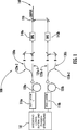
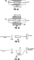
Bezugnehmend auf
Der Output der Oszillatoren wird vorzugsweise durch optische Isolatoren (nicht gezeigt) geleitet, um ihre Empfindlichkeit bezüglich Rückreflektionen zu minimieren. Die Wiederholungsraten der zwei Oszillatoren können überwacht werden durch Verwendung von zwei Abzweigkopplern (top-couplers), die in den Output der zwei Oszillatoren eingesetzt werden und die einen kleinen Bruchteil des Outputs der Oszillatoren auf zwei Detektoren (nicht gezeigt) leiten, die Signale, welche die Wiederholungsrate repräsentieren, an die Steuereinheit
Die Oszillatoren können so konstruiert werden, dass sie bei entsprechenden Wiederholungsraten von f und f + δ arbeiten, wobei δ << f. Alternativ kann die Wiederholungsrate des zweiten Oszillators als nf + δ gewählt werden, wobei n eine ganze Zahl ist. Der Unterschied zwischen ihren Wiederholungsraten δ oder (n – 1)f + δ für den Fall von stark verschiedenen Wiederholungsraten kann dann durch das Wiederholungsraten-Steuerelement
Die Outputs der Oszillatoren sind an zwei Faserverstärker
Im Beispiel der
Dispersionskompensation wird in den optischen Pfaden aller Arme durchgeführt, um Dispersion zu kompensieren, zum Beispiel mit einer Reihe von dispersionskompensierenden Elementen, die einen Dispersionskompensator bilden. Zumindest ein Teil der Arme kann aus identischen Komponenten konstruiert werden, einschließlich der verschiedenen dispersionskompensierenden Elemente. Dispersionskompensierende Elemente können optische Elemente zur Pulskomprimierung umfassen, um Femtosekunden-Pulse hoher Qualität bereitzustellen und können eine vollständige Dispersionskompensation bereitstellen oder leicht negativ oder positiv gechirpte Pulse an ihrem Ausgang produzieren. Wenn vollständige Dispersionskompensation verwendet wird, sind die Output-Pulse nahezu Fourier-limitiert (transform limited).Dispersion compensation is performed in the optical paths of all arms to compensate for dispersion, for example with a series of dispersion compensating elements forming a dispersion compensator. At least a portion of the arms may be constructed of identical components, including the various dispersion-compensating elements. Dispersion compensating elements can include pulse compression optical elements to provide high quality femtosecond pulses and can provide complete dispersion compensation or easily produce negative or positive chirped pulses at their output. When complete dispersion compensation is used, the output pulses are nearly Fourier limited (transform limited).
Ein Dispersionskompensator kann verschiedene Faserelemente umfassen und kann mit einem integrierten, vollständig in Fasermaterial ausgeführten Design implementiert werden, wie weiter unten mit Bezug auf
Optische Pulse, die sich in den Armen
In verschiedenen Implementierungen umfasst ein Frequenzwandlungsabschnitt vorzugsweise eine hochgradig nichtlineare Faser, einen periodisch gepolten LiMbO3(PPLN)-Wellenleiter, einen Siliziumwellenleiter oder irgendeinen anderen geeigneten nichtlinearen Wellenleiter. Ein Element kann auch optisch mit Mustern versehen werden oder periodisch oder aperiodisch gepolt werden oder periodische Veränderungen der Nichtlinearität zweiter Ordnung entlang seiner Länge haben. Die Frequenzwandlungsabschnitte
Die Differenzfrequenz-Erzeugung (DFG) wird ausgeführt in nichtlinearen Frequenzwandlungsabschnitten
In verschiedenen Ausführungsformen werden die optischen Signalpulse, die von den Verstärkern ausgegeben werden, weitergeleitet durch einen optischen Isolator, bevor sie in die Dispersionskompensations- und die Frequenzwandlungsstufen eingeleitet werden. Geeignete Zeitverzögerungen zwischen den zwei Oszillatoren werden weiterhin eingeführt, um einen Pulsüberlapp in den DFG-Elementen und dem Strahlteiler
Eine ganz aus Fasermaterial ausgeführte Konstruktion eines Dispersionskompensators und eines nichtlinearen Frequenzwandlungsabschnitts in jedem Arm liefert einige Vorteile. Ein Vorteil bei der Verwendung einer hochgradig nichtlinearen Faser für die Frequenzwandlungseinheiten
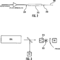
In dem in
Die Output-Pulse des Verstärkers, die von der Übertragungsphase
Die hochgradig nichtlineare Faser
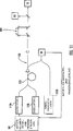
Ein optisches Abbildungssystem, das einen CDSL umfasst, wird in
Der Detektor D1 überwacht Schwebungsfrequenzen in dem Radiofrequenz-Bereich. Wegen des Skalierens der optischen Frequenzen mit den Radiofrequenzen über einen Skalenfaktor frep/δ in einem CDSL können wir die Funktion des CDSL so interpretieren, dass es ein Frequenzgitter im Radiowellenbereich repräsentiert zum Skalieren von Radiowellen zu optischen Frequenzen; jede optische Frequenz wird eindeutig mit einer 1:1-Beziehung auf eine Radiofrequenz abgebildet. Die Differenzfrequenz–Erzeugung, wie sie in
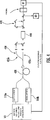
Eine alternative Ausführungsform eines CDSL wird in
Um eine Verschlechterung des Signals wegen der nichtlinearen Wechselwirkung in dem Zeitraum, in dem sich die Outputpulse der beiden Oszillatoren in dem DFG-Abschnitt zeitlich überlappen, zu verhindern, können die Detektoren elektronisch gesteuert (gated) werden, dass sie in diesen Zeiträumen nicht empfänglich sind. Um ein Interferenzsignal zu Zeiten zu erhalten, wenn die Outputpulse der beiden Oszillatoren nicht zeitlich überlappen, kann eine optische Verzögerungslinie
Ein anderes Beispiel eines CDSL wird in
Im Gegensatz zu dem System, welches mit Bezug auf
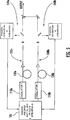
Wie im
In
In
Eine noch schnellere Steuerung der Phasenschlupffrequenz (carrier-envelope offset frequency) kann über einen innerhalb des Resonators angeordneten akustooptischen Modulator (AOM)
In
Andere Mittel zur Steuerung der Phasenschlupffrequenz können auch eingesetzt werden; zum Beispiel kann die Temperatur des innerhalb des Resonators angeordneten sättigbaren Absorbers moduliert werden. Verschiedene Kombinationen können auch eingesetzt werden. Darüber hinaus können die Rückkopplungssysteme der
In
Statt fceo mit einem f-2f-Interferometer zu steuern, kann fceo auch durch Referenzieren des Frequenzkamms eines modengekoppelten Lasers auf die Fabry-Perot-Resonanzen eines passiven Resonators gesteuert werden. Diese Technik hat gewisse Vorteile: keine eine Oktave umfassende Kontinuum-Erzeugung ist erforderlich und relativ kleine Leistungsniveaus, die mit einem Teil der Oszillatorleistung bereitgestellt werden können, sind ausreichend. Dieses Verfahren wird beschrieben in
Eine Ausführungsform, welche externe Resonatoren verwendet, wird in
Die Gitter
Als eine Alternative zur Nutzung von passiven Resonatoren als stabile Bezugsgrößen für die Steuerung von Wiederholungsrate und Trägerphase der CDSLs können Dauerstrich-Referenzlaser (cw reference lasers)
Eine kompakte und hochintegrierte Konfiguration eines CDSL wird in
Da Δfb und δ bekannt sind und n, m über die oben beschriebene Kalibrierungsprozedur erhalten werden können, können wir Δfceo aus den Gleichungen (2) oder (3) mit großer Präzision erhalten.Since Δf b and δ are known and n, m can be obtained through the calibration procedure described above, we can obtain Δf ceo from equations (2) or (3) with great precision.
Es kann leicht gezeigt werden, dass für Δfceo ≠ 0 das Frequenzgitter im Radiowellenbereich in der Frequenz verschoben ist im Vergleich zur Gleichung (1) und die Beziehung zwischen optischen fopt und Radiowellenfrequenzen frf wie folgt modifiziert ist.
Hierbei können wir Gleichung (5) vereinfachen, da fceo << fopt. In diesem Beispiel wird Δfceo stabilisiert statt der einzelnen Phasenschlupffrequenzen (carrier-envelope offset frquencies), um ein genaues Radiowellen-Frequenzgitter zur Messung von optischen Frequenzen zu erhalten.Here we can simplify equation (5), since f ceo << f opt . In this example, Δf ceo stabilizes instead of the single carrier-shift offset frequencies to obtain an accurate radio wave frequency grating for measuring optical frequencies.
Um die bestmögliche Präzision über einen langen Zeitraum für Frequenzmessungen mit einem CDSL-System zu erhalten, werden beide Oszillatoren vorzugsweise in eine enge Nachbarschaft gepackt, um irgendwelche thermischen Fluktuationen von Laserparametern zwischen den beiden Lasern anzugleichen. Ebenso wird der Einzelfrequenz-Referenzlaser auch vorzugsweise mit einer guten thermischen Steuerung zusammengepackt.In order to obtain the best possible long-term precision for frequency measurements with a CDSL system, both oscillators are preferably packed in close proximity to equalize any thermal fluctuations in laser parameters between the two lasers. Likewise, the single frequency reference laser is also preferably packed together with good thermal control.
Zusätzlich kann das System mit Verstärkern und nichtlinearen Frequenzwandlungsanschnitten ausgestattet werden, um einen vergrößerten spektralen Bereich abzudecken. Eine zeitliche Verzögerungsstrecke
Das System der
Die oben beschriebenen Ausführungsformen können auf verschiedene Arten kombiniert werden, um alternative Implementierungen zu erzeugen. Viele Möglichkeiten existieren, und verschiedene Modifikationen können gemacht werden basierend auf spezifischen Anwendungen. Zum Beispiel kann ein nichtlinearer Frequenzwandlungsabschnitt mit mindestens einem nichtlinearen Faserverstärker konfiguriert werden, um ein Spektrum zu verbreitern.The embodiments described above may be combined in various ways to create alternative implementations. Many possibilities exist, and various modifications can be made based on specific applications. For example, a non-linear frequency conversion section may be configured with at least one non-linear fiber amplifier to broaden a spectrum.
Zurückgehend zur
Komplexere Modifikationen des Radiowellen-Frequenzgitters und der Relation zwischen optischen und Radiowellenfrequenzen können erhalten werden für kleine kontinuierliche Veränderungen von Δfceo wie auch von δ. Durch den Einsatz einer Phasenüberwachungseinheit können die entsprechenden Korrekturen des Radiowellen-Frequenzgitters berechnet werden, um eine genaue Umwandlung von Radiowellen in optische Frequenzen zu erhalten. Solche Korrekturen zu dem Radiowellen-Frequenzgitter wurden durch Giacarri diskutiert und werden hier nicht weiter beschrieben. Ähnliche Korrekturen können auch angewendet werden, wenn Δfceo mit einem f-2f-Interferometer überwacht wird. Da das f-2f-Interferometer ein direktes Ablesen von fceo für jeden Oszillator unter Verwendung von Radiowellen-Techniken erlaubt, kann Δfceo leicht berechnet werden und die optischen Frequenzen können unter Verwendung von Gleichung (5) berechnet werden.More complex modifications of the radio frequency frequency grid and the relation between optical and radio wave frequencies can be obtained for small continuous changes of Δf ceo as well as δ. By using a phase monitoring unit, the corrections of the radio wave frequency grating can be calculated to obtain an accurate conversion of radio waves into optical frequencies. Such corrections to the radio wave frequency grid have been discussed by Giacarri and will not be further described here. Similar corrections can also be applied if Δf ceo is monitored with an f-2f interferometer. Since the f-2f interferometer allows direct reading of f ceo for each oscillator using radio wave techniques, Δf ceo can be easily calculated and the optical frequencies can be calculated using equation (5).
Die Abbildungsanordnung, wie sie mit Bezug auf
Demnach haben die Erfinder CDSLs und einige ihrer Anwendungen beschrieben und verschiedene Alternativen für eine Implementierung einschließlich hochgradig integrierten Konfigurationen.Thus, the inventors have described CDSLs and some of their applications, and various alternatives for implementation, including highly integrated configurations.
In mindestens einer Ausführungsform umfasst ein kohärentes duales Abtastlasersystem (CDSL) zwei passiv modengekoppelte Faseroszillatoren. Die Oszillatoren werden konfiguriert, um bei leicht verschiedenen Wiederholungsraten zu arbeiten, so dass eine Differenz δfr in den Wiederholungsraten klein ist verglichen mit den Werten fr1 und fr2 der Wiederholungsraten der Oszillatoren. Das CDSL-System umfasst auch einen nichtlinearen Frequenzwandlungsabschnitt, der mit jedem Oszillator optisch verbunden ist. Der Abschnitt umfasst ein nichtlineares optisches Element, welches einen frequenzgewandelten spektralen Output erzeugt, der eine spektrale Bandbreite und einen Frequenzkamm hat, der Harmonische der Oszillator-Wiederholungsraten umfasst.In at least one embodiment, a coherent dual sampling laser system (CDSL) comprises two passively mode-locked fiber oscillators. The oscillators are configured to operate at slightly different repetition rates, so that a difference δf r in the repetition rates is small compared to the values f r1 and f r2 of the repetition rates of the oscillators. The CDSL system also includes a non-linear frequency conversion section optically connected to each oscillator. The section comprises a nonlinear optical element which generates a frequency converted spectral output having a spectral bandwidth and a frequency comb comprising harmonics of the oscillator repetition rates.
In verschiedenen Ausführungsformen finden sich die folgenden Merkmale:
Ein Frequenzwandlungsabschnitt umfasst einen Output-Abschnitt, welcher mehrere Input-Frequenzen empfängt und kombiniert und einen spektralen Output bei einer Differenzfrequenz derselben erzeugt, und das System umfasst einen zwischengeschalteten nichtlinearen Frequenzwandlungsabschnitt zwischen dem mindestens einen Oszillator und dem Output-Abschnitt, wobei der zwischengeschaltete Abschnitt ein breitbandiges Spektrum erzeugt, welches eine Bandbreite hat, die wesentlich größer als ein Oszillator-Spektrum ist.In various embodiments, the following features can be found:
A frequency conversion section comprises an output section that receives and combines a plurality of input frequencies and generates a spectral output at a difference frequency thereof, and the system includes an intermediate non-linear frequency conversion section between the at least one oscillator and the output section, the intermediate section produces broadband spectrum, which has a bandwidth that is much larger than an oscillator spectrum.
Ein CDSL wird in einem Messsystem angeordnet, das spektrale Information nutzt, und ein spektraler Output wird verwendet, um eine physikalische Eigenschaft einer Testprobe mit spektralen Komponenten innerhalb der spektralen Bandbreite zu untersuchen.A CDSL is placed in a measurement system that uses spectral information, and a spectral output is used to examine a physical property of a test sample with spectral components within the spectral bandwidth.
Ein CDSL wird in einem Abbildungssystem angeordnet für eine oder mehrere der folgenden Aufgaben: optisches Abbilden, Mikroskopie, Mikrospektroskopie und/oder THz-Abbilden.A CDSL is placed in an imaging system for one or more of the following tasks: optical imaging, microscopy, microspectroscopy, and / or THz imaging.
Ein auf einem CDSL basierendes Messsystem kann ein Element zum optischen Abtasten (Scanning) umfassen.A CDSL-based measurement system may include an optical scanning element.
Ein Phasenregelkreis steuert die Differenz zwischen den Wiederholungsraten der Oszillatoren.A phase locked loop controls the difference between the repetition rates of the oscillators.
Ein Radiowellenspektrumanalysator erzeugt einen Output bei Radiowellenfrequenzen, die zu den optischen Frequenzen über einen Konversionsfaktor (fr1 + fr2)/2δfr in Beziehung stehen.A radio frequency spectrum analyzer produces output at radio wave frequencies related to the optical frequencies via a conversion factor (f r1 + f r2 ) / 2δf r .
Modengekoppelte Faseroszillatoren umfassen einen Nd-, Yb-, Tm- oder Er-Faseroszillator.Mode-locked fiber oscillators include an Nd, Yb, Tm or Er fiber oscillator.
Mindestens ein Faserverstärker wird umfasst zum Verstärken von einem oder mehreren Oszillator-Outputs.At least one fiber amplifier is included for amplifying one or more oscillator outputs.
Ein integrierter, ganz aus Fasermaterial bestehender Dispersionskompensator und ein nichtlinearer Frequenzwandlungsabschnitt sind eingeschlossen, wobei der integrierte Abschnitt eine oder mehrere der folgenden Fasern umfasst: eine hochgradig nichtlineare Faser, eine photonische Kristall-Faser, eine dispersionskompensierende Faser und/oder eine Faser, die ein zentrales Luftloch aufweist.An integrated all fiber material dispersion compensator and a non-linear frequency conversion section are included, the integrated section comprising one or more of the following: a highly nonlinear fiber, a photonic crystal fiber, a dispersion compensating fiber, and / or a central fiber Having air hole.
Ein System umfasst ein voluminöses (bulk) optisches Element zur Dispersionskompensation, welches mindestens eines der folgenden Elemente umfasst: ein Gitter-Paar, ein Prismenpaar und/oder ein Gitter-Prismen-System, wobei die Dispersionskompensation eine Pulskomprimierung umfasst.A system comprises a bulk dispersion compensation optical element comprising at least one of a grid pair, a prism pair and / or a grating prism system, the dispersion compensation comprising pulse compression.
Ein nichtlinearer Frequenzwandlungsabschnitt umfasst einen Differenzfrequenz-Erzeuger.A non-linear frequency conversion section comprises a difference frequency generator.
Ein nichtlinearer Frequenzabschnitt umfasst einen Superkontinuum-Erzeuger, der nach dem mindestens einen Oszillator angeordnet ist.A non-linear frequency section comprises a supercontinuum generator arranged after the at least one oscillator.
Ein modengekoppelter Faseroszillator erzeugt Pulse bei einer Wiederholungsrate, die größer als ungefähr 250 MHz ist.A mode locked fiber oscillator generates pulses at a repetition rate greater than about 250 MHz.
In mindestens einer Ausführungsform umfasst ein kohärentes duales Abtastlasersystem zwei passiv modengekoppelte Faseroszillatoren. Die Oszillatoren sind konfiguriert, um bei leicht verschiedenen Wiederholungsraten zu arbeiten, so dass eine Differenz δfr bei den Wiederholungsraten klein ist im Vergleich zu den Werten fr1 und fr2 der Wiederholungsraten der beiden Oszillatoren. Der CDSL umfasst auch einen nichtlinearen Frequenzwandlungsabschnitt, der optisch an jeden Oszillator gekoppelt ist, wobei der Abschnitt ein nichtlineares optisches Element umfasst, welches einen frequenzgewandelten spektralen Output erzeugt, der eine spektrale Bandbreite und eine Frequenzkammstruktur mit einem Frequenzabstand hat, der den Oszillator-Wiederholungsraten entspricht. Der nichtlineare Frequenzwandlungsabschnitt erzeugt einen spektralen Output, der wesentlich breiter als der spektrale Output von jedem Oszillator ist.In at least one embodiment, a coherent dual sampling laser system includes two passively mode locked fiber oscillators. The oscillators are configured to be at light at different repetition rates, so that a difference δf r at the repetition rates is small compared to the values f r1 and f r2 of the repetition rates of the two oscillators. The CDSL also includes a nonlinear frequency conversion section optically coupled to each oscillator, the section comprising a nonlinear optical element that generates a frequency converted spectral output having a spectral bandwidth and a frequency comb structure with a frequency spacing equal to the oscillator repetition rates , The non-linear frequency conversion section generates a spectral output that is significantly wider than the spectral output of each oscillator.
In verschiedenen Ausführungsformen finden sich die folgenden Merkmale:
Ein Mittel zum Überwachen der Differenz zwischen den Phasenschlupffrequenzen (carrier envelope offset frequencies) der beiden Laser ist umfasst, wobei die Information, die von dem Überwachungsmittel erzeugt wird, eine 1:1-Korrespondenz zwischen Radiowellenfrequenzen und optischen Frequenzen liefert.In various embodiments, the following features can be found:
A means for monitoring the difference between the carrier envelope offset frequencies of the two lasers is included, wherein the information generated by the monitoring means provides a one-to-one correspondence between radio wave frequencies and optical frequencies.
Eine Korrespondenz wird mit einer 1:1-Abbildung der Radiowellenfrequenzen zu den optischen Frequenzen dargestellt.A correspondence is represented with a 1: 1 mapping of the radio wave frequencies to the optical frequencies.
Ein f-2f-Interferometer ist umfasst zur Steuerung der Phasenschlupffrequenz von jedem Laser.An f-2f interferometer is included to control the phase-slip frequency of each laser.
Ein Rückkopplungssystem ist umfasst zum Stabilisieren der Differenz in den Phasenschlupffrequenzen (carrier envelope offset frequencies) der beiden Oszillatoren.A feedback system is included for stabilizing the difference in the carrier envelope offset frequencies of the two oscillators.
Eine Phasenschlupffrequenz-Information, die durch das Rückkopplungssystem erzeugt wird, wird verwendet, um ein Frequenzgitter im Radiowellenbereich zu erzeugen, das eine 1:1-Entsprechung zu einem Frequenzgitter im optischen Bereich hat.Phase-slip frequency information generated by the feedback system is used to generate a frequency grid in the radio wave region which has a one-to-one correspondence to a frequency grating in the optical domain.
Ein Rückkopplungssystem umfasst einen Einzelfrequenz-Referenzlaser.A feedback system includes a single frequency reference laser.
Zwei Referenzresonatoren werden verwendet zur Steuerung der Phasenschlupffrequenz von jedem Oszillator.Two reference resonators are used to control the phase-slip frequency of each oscillator.
Ein Referenzresonator wird verwendet für die Steuerung der Phasenschlupffrequenz von jedem Oszillator.A reference resonator is used to control the phase-slip frequency of each oscillator.
Zwei Einzelfrequenz-Referenzlaser werden verwendet zur Steuerung der Phasenschlupffrequenz von jedem Oszillator.Two single-frequency reference lasers are used to control the phase-slip frequency of each oscillator.
Ein nichtlinearer Frequenzwandlungsabschnitt umfasst eine hochgradig nichtlineare Faser.A non-linear frequency conversion section comprises a highly non-linear fiber.
Ein Verhältnis einer Wiederholungsrate zu der Differenz in den Wiederholungsraten ist mindestens ungefähr 106 und kann auch im Bereich von ungefähr 106 bis ungefähr 109 liegen.A ratio of a repetition rate to the difference in repetition rates is at least about 10 6 and may also be in the range of about 10 6 to about 10 9 .
Die Wiederholungsraten fr1, fr2 und das Verhältnis einer Wiederholungsrate zu der Differenz der Wiederholungsraten sind hinreichend groß, um eine Radiowellenfrequenz in eine optische Frequenz umzuwandeln.The repetition rates f r1 , f r2 and the ratio of a repetition rate to the difference of the repetition rates are sufficiently large to convert a radio frequency to an optical frequency.
Mindestens eine Ausführungsform umfasst ein System zum Abbilden in den THz-Spektralbereich. Das Abbildungssystem umfasst ein kohärentes duales Abtastlasersystem (CDSL), das zwei passiv modengekoppelte Faseroszillatoren hat. Die modengekoppelten Oszillatoren sind konfiguriert, um bei leicht verschiedenen Wiederholungsraten zu arbeiten, sodass eine Differenz δfr zwischen den Wiederholungsraten klein ist im Vergleich zu den Werten fr1 und fr2 der Wiederholungsraten der Oszillatoren. Das System umfasst ein Material, welches THz-Strahlung emittiert als Antwort auf einen Output des CDSL und einen Detektor, der auf die THz-Strahlung anspricht.At least one embodiment includes a system for mapping into the THz spectral range. The imaging system comprises a coherent dual sampling laser (CDSL) system having two passively mode-locked fiber oscillators. The mode-locked oscillators are configured to operate at slightly different repetition rates, so that a difference δf r between the repetition rates is small compared to the values f r1 and f r2 of the repetition rates of the oscillators. The system includes a material that emits THz radiation in response to an output of the CDSL and a detector responsive to the THz radiation.
In mindestens einer Ausführungsform umfasst ein kohärentes duales Abtastlasersystem zwei passiv modengekoppelte Oszillatoren, die mindestens zwei Züge von kurzen optischen Pulsen erzeugen. Die Oszillatoren werden konfiguriert, um bei leicht verschiedenen Wiederholungsraten zu arbeiten, so dass eine Differenz zwischen den Wiederholungsraten δfr klein ist im Vergleich zu den Werten fr1 und fr2 der Wiederholungsraten der Oszillatoren. Das System umfasst einen Strahlkombinierer für das räumliche Kombinieren der Züge von kurzen optischen Pulsen, um sie entlang eines gemeinsamen optischen Pfads unterhalb (downstream) des Strahlkombinierers auszubreiten. Ein nichtlineares optisches Element zum spektralen Verbreitern von mindestens einem Zug der kurzen optischen Pulse wird umfasst, die sich entlang des gemeinsamen optischen Pfads ausbreiten. Ein duales Arm-Interferometer wird mit verschiedenen Armlängen konfiguriert, um die Interferenz zwischen Pulszügen zu detektieren, wenn die Pulse nicht zeitlich überlappend sind in der Zeit, bevor sie in das Interferometer hineinkommen.In at least one embodiment, a coherent dual sampling laser system includes two passively mode-locked oscillators that produce at least two trains of short optical pulses. The oscillators are configured to operate at slightly different repetition rates, so that a difference between the repetition rates δf r is small compared to the values f r1 and f r2 of the repetition rates of the oscillators. The system includes a beam combiner for spatially combining the trains of short optical pulses to propagate them along a common optical path downstream of the beam combiner. A nonlinear optical element for spectrally broadening at least one train of short optical pulses is propagated along the common optical path. A dual arm interferometer is configured with different arm lengths to detect the interference between pulse trains when the pulses are not overlapping in time in time before entering the interferometer.
In verschiedenen Ausführungsformen entspricht eine Armlängendifferenz ungefähr der Hälfte der Resonatorumlaufzeit der Oszillatoren.In various embodiments, an arm length difference corresponds to approximately half the resonator cycle time of the oscillators.
In mindestens einer Ausführungsform umfasst ein kohärentes duales Abtastlasersystem zwei passiv modengekoppelte Faseroszillatoren, die zwei separate Züge von kurzen optischen Pulsen erzeugen. Die Oszillatoren werden angepasst, um bei leicht verschiedenen Wiederholungsraten zu arbeiten, so dass eine Differenz δfr zwischen den Wiederholungsraten klein ist im Vergleich zu den Werten fr1 und fr2 der Wiederholungsraten der Oszillatoren. Ein Rückkopplungssystem stabilisiert die Differenz der Phasenschlupffrequenzen (carrier envelope offset frequencies) der beiden Oszillatoren, und das Rückkopplungssystem umfasst einen Einzelfrequenz-Laser. Ein Strahlkombinierer kombiniert die Züge von kurzen optischen Pulsen räumlich, um sie entlang eines gemeinsamen optischen Pfads unterhalb (downstream) des Strahlkombinierers auszubreiten. Das System umfasst ein nichtlineares optisches Element zum spektralen Verbreitern von mindestens einem Zug von kurzen optischen Pulsen, der sich entlang eines gemeinsamen optischen Pfads ausbreitet. Ein duales Arm-Interferometer wird konfiguriert mit verschiedenen Armlängen, so dass eine Interferenz zwischen Pulszügen detektiert werden kann, wenn die Pulse nicht zeitlich überlappend sind in der Zeit, bevor sie in das Interferometer hereinkommen.In at least one embodiment, a coherent dual sampling laser system includes two passively mode-locked fiber oscillators that produce two separate trains of short optical pulses. The oscillators are adjusted to operate at slightly different repetition rates, so that a difference δf r between the Repetition rates is small compared to the values f r1 and f r2 of the repetition rates of the oscillators. A feedback system stabilizes the difference of the carrier envelope offset frequencies of the two oscillators, and the feedback system comprises a single-frequency laser. A beam combiner spatially combines the trains of short optical pulses to propagate them along a common optical path downstream of the beam combiner. The system includes a nonlinear optical element for spectrally broadening at least one train of short optical pulses propagating along a common optical path. A dual arm interferometer is configured with different arm lengths so that interference between pulse trains can be detected if the pulses are not overlapping in time in time before entering the interferometer.
Während nur bestimmte Ausführungsformen hier spezifisch beschrieben worden sind, wird demnach deutlich, dass zahlreiche Modifikationen an ihnen gemacht werden können, ohne vom Geist und dem Umfang der Erfindung abzuweichen. Außerdem werden Abkürzungen nur benutzt, um die Lesbarkeit der Beschreibung und der Ansprüche zu erhöhen. Es sollte bemerkt werden, dass diese Abkürzungen nicht dazu beabsichtigt sind, die Allgemeinheit der verwendeten Begriffe zu verringern, und sie sollten nicht so verstanden werden, dass sie den Umfang der Patentansprüche auf die hier beschriebenen Ausführungsformen reduzieren.Thus, while particular embodiments have been specifically described herein, it will be apparent that numerous modifications can be made thereto without departing from the spirit and scope of the invention. In addition, abbreviations are used only to increase the readability of the description and claims. It should be noted that these abbreviations are not intended to reduce the generality of the terms used, and they should not be construed to reduce the scope of the claims to the embodiments described herein.
ZITATE ENTHALTEN IN DER BESCHREIBUNG QUOTES INCLUDE IN THE DESCRIPTION
Diese Liste der vom Anmelder aufgeführten Dokumente wurde automatisiert erzeugt und ist ausschließlich zur besseren Information des Lesers aufgenommen. Die Liste ist nicht Bestandteil der deutschen Patent- bzw. Gebrauchsmusteranmeldung. Das DPMA übernimmt keinerlei Haftung für etwaige Fehler oder Auslassungen.This list of the documents listed by the applicant has been generated automatically and is included solely for the better information of the reader. The list is not part of the German patent or utility model application. The DPMA assumes no liability for any errors or omissions.
Zitierte PatentliteraturCited patent literature
- US 5778016 [0002, 0005, 0042, 0042] US 5778016 [0002, 0005, 0042, 0042]
- US 6396856 [0002, 0042, 0042] US 6396856 [0002, 0042, 0042]
- US 5748399 [0003] US 5748399 [0003]
- WO 2007/045461 [0005] WO 2007/045461 [0005]
- US 7203402 [0006] US 7203402 [0006]
- US 6785303 [0038] US Pat. No. 6785303 [0038]
- US 7191705 [0042] US Pat. No. 7,119,170 [0042]
- US 11/546998 [0042, 0047, 0067] US 11/546998 [0042, 0047, 0067]
- US 7190705 [0042, 0044, 0047, 0049, 0050, 0068] US 7190705 [0042, 0044, 0047, 0049, 0050, 0068]
- US 6885683 [0060] US 6885683 [0060]
- US 7414780 [0060] US 7414780 [0060]
- US 7496260 [0061] US 7496260 [0061]
- US 7490705 [0067] US 7490705 [0067]
Zitierte Nicht-PatentliteraturCited non-patent literature
- Keilmann et al. in dem Artikel „Time domain mid-infrared frequency-comb spectrometer”, Opt. Lett., vol. 29, S. 1542–1544 (2004) [0004] Keilmann et al. in the article "Time domain mid-infrared frequency-comb spectrometer", Opt. Lett., vol. 29, pp. 1542-1544 (2004) [0004]
- Keilmann et al. [0005] Keilmann et al. [0005]
- J. Mandon et al., „Fourier transform spectroscopy with a laser frequency comb”, in Nature Photonics, 2009 [0007] Mandon, et al., "Fourier transform spectroscopy with a laser frequency comb," in Nature Photonics, 2009 [0007]
- P. Giaccari et al., „Active Fourier-transform spectroscopy combining the direct RF beating of two fiber-based mode-locked lasers with a novel referencing method”, Opt. Express., vol. 16, S. 4347 (2008) [0008] P. Giaccari et al., "Active Fourier-transform spectroscopy combining the direct RF beating of two fiber-based mode-locked lasers with a novel referencing method", Opt. Express., Vol. 16, p. 4347 (2008) [0008]
- I. Coddington et al., ”Coherent Multiheterodyne Spectroscopy Using Stabilized Optical Frequency Combs”, Phys. Rev. Lett. 100, 13902 (2008) [0008] Coddington et al., Coherent Multiheterodyne Spectroscopy Using Stabilized Optical Frequency Combs, Phys. Rev. Lett. 100, 13902 (2008) [0008]
- P. Giaccari et al., „Active Fourier-transform spectroscopy combining the direct RF beating of two faber-based mode-locked lasers with a novel referencing method”, Opt. Express., vol. 16, S. 4347 (2008) [0040] P. Giaccari et al., "Active Fourier transform spectroscopy combining the direct RF beating of two faber-based mode-locked lasers with a novel referencing method", Opt. Express., Vol. 16, p. 4347 (2008) [0040]
- N. Newbury und W. Swann, „Low-noise fiber-laser frequency combs”, Journal of the Optical Society of America B 24, S. 1756–1770 (2007) [0055] N. Newbury and W. Swann, "Low-noise fiber-laser frequency combs", Journal of the Optical Society of America B 24, pp. 1756-1770 (2007) [0055]
- R. Jason Jones und Jean-Claude Diels „Stabilization for Femtosecond Lasers for Optical Frequency Metrology and Direct Optical to RadioSynthesis” PRL 86, S. 3288 (2001) [0076] R. Jason Jones and Jean-Claude Diels "Stabilization for Femtosecond Lasers for Optical Frequency Metrology and Direct Optical to Radio Synthesis" PRL 86, p. 3288 (2001) [0076]
- R. Jason Jones et al. ”Precision stabilization of femtosecond lasers to high-finesse optical cavities” Phys. Rev. A 69, 051803 (2004) [0076] Jason Jones et al. "Precision stabilization of femtosecond lasers to high-finesse optical cavities" Phys. Rev. A 69, 051803 (2004) [0076]
- I. Coddington et al., „Coherent Multiheterodyne Spectroscopy Using Stabilized Optical Frequency Combs”, Phys. Rev. Lett. 100, 13902 (2008) [0079] Coddington et al., Coherent Multiheterodyne Spectroscopy Using Stabilized Optical Frequency Combs, Phys. Rev. Lett. 100, 13902 (2008) [0079]
- Yasui et al. in Appl. Phys. Lett., vol. 88, S. 211104–1 bis 3 (2006) [0090] Yasui et al. in Appl. Phys. Lett., Vol. 88, p. 211104-1 to 3 (2006) [0090]
- Yasui et al. [0090] Yasui et al. [0090]
Claims (30)
Applications Claiming Priority (3)
| Application Number | Priority Date | Filing Date | Title |
|---|---|---|---|
| US12/399,435 US8120778B2 (en) | 2009-03-06 | 2009-03-06 | Optical scanning and imaging systems based on dual pulsed laser systems |
| US12/399,435 | 2009-03-06 | ||
| PCT/US2010/023123 WO2010101690A1 (en) | 2009-03-06 | 2010-02-04 | Optical scanning and imaging systems based on dual pulsed laser systems |
Publications (1)
| Publication Number | Publication Date |
|---|---|
| DE112010000981T5 true DE112010000981T5 (en) | 2012-09-27 |
Family
ID=42677980
Family Applications (2)
| Application Number | Title | Priority Date | Filing Date |
|---|---|---|---|
| DE112010000981T Withdrawn DE112010000981T5 (en) | 2009-03-06 | 2010-02-04 | Optical scanning and imaging systems based on dual-pulse laser systems |
| DE112010006131.9T Active DE112010006131B3 (en) | 2009-03-06 | 2010-02-04 | Optical scanning and imaging systems based on dual-pulsed laser systems |
Family Applications After (1)
| Application Number | Title | Priority Date | Filing Date |
|---|---|---|---|
| DE112010006131.9T Active DE112010006131B3 (en) | 2009-03-06 | 2010-02-04 | Optical scanning and imaging systems based on dual-pulsed laser systems |
Country Status (5)
| Country | Link |
|---|---|
| US (6) | US8120778B2 (en) |
| JP (1) | JP5663499B2 (en) |
| CN (2) | CN103606815A (en) |
| DE (2) | DE112010000981T5 (en) |
| WO (1) | WO2010101690A1 (en) |
Families Citing this family (97)
| Publication number | Priority date | Publication date | Assignee | Title |
|---|---|---|---|---|
| US7414780B2 (en) | 2003-06-30 | 2008-08-19 | Imra America, Inc. | All-fiber chirped pulse amplification systems |
| US7486705B2 (en) | 2004-03-31 | 2009-02-03 | Imra America, Inc. | Femtosecond laser processing system with process parameters, controls and feedback |
| US8120778B2 (en) | 2009-03-06 | 2012-02-21 | Imra America, Inc. | Optical scanning and imaging systems based on dual pulsed laser systems |
| US8571075B2 (en) | 2010-11-29 | 2013-10-29 | Imra America, Inc. | Frequency comb source with large comb spacing |
| US8913636B2 (en) * | 2009-04-29 | 2014-12-16 | Montana State University | Precise broadband frequency modulated laser |
| US8411352B2 (en) * | 2009-08-17 | 2013-04-02 | Coherent, Inc. | Pulsed fiber-MOPA with widely-variable pulse-duration |
| DE112010003904T5 (en) | 2009-10-02 | 2013-03-07 | Imra America, Inc. | Optical signal processing with mode-locked lasers |
| US9158177B2 (en) * | 2010-11-24 | 2015-10-13 | Fianium Ltd. | Optical systems |
| FR2968763B1 (en) * | 2010-12-08 | 2014-06-06 | Topnir Systems | METHOD AND DEVICE FOR CHARACTERIZING A PRODUCT, METHOD AND DEVICE FOR DETECTING THE TRANSITION OF A PRODUCT, METHOD AND DEVICE FOR DETERMINING THE COMPOSITION OF A PRODUCT |
| CN102175316B (en) * | 2011-01-19 | 2012-07-18 | 天津大学 | X-Y galvanometer scanning hyper spectral image data acquisition method |
| US8787410B2 (en) | 2011-02-14 | 2014-07-22 | Imra America, Inc. | Compact, coherent, high brightness light sources for the mid and far IR |
| DE102011000905A1 (en) * | 2011-02-24 | 2012-08-30 | Leica Microsystems Cms Gmbh | Pulse combiner for the different spectral colors of a supercontinuum laser |
| EP2686732A4 (en) | 2011-03-14 | 2015-03-11 | Imra America Inc | Broadband generation of mid ir, coherent continua with optical fibers |
| US20120253721A1 (en) * | 2011-03-29 | 2012-10-04 | Georgia Tech Research Corporation | Determining characteristics of ultrashort pulses |
| JP2013008950A (en) * | 2011-05-23 | 2013-01-10 | Panasonic Corp | Light source device and image display apparatus |
| US8792525B2 (en) | 2011-05-27 | 2014-07-29 | The Regents Of The University Of Colorado, A Body Corporate | Compact optical frequency comb systems |
| AU2012101920A4 (en) | 2011-08-29 | 2014-11-13 | Genia Photonics Inc. | System and method for synchronizing light pulses at a selected location |
| US8861555B2 (en) | 2011-11-25 | 2014-10-14 | Imra America, Inc. | Compact coherent high brightness light source for the mid-IR and far IR |
| DE102012001357A1 (en) | 2012-01-24 | 2013-07-25 | Menlo Systems Gmbh | Optical arrangement and method for generating variable delay light pulses |
| CN102607720B (en) * | 2012-03-02 | 2014-07-16 | 北京航空航天大学 | Method and system for measuring optical distance |
| WO2013127370A1 (en) * | 2012-03-02 | 2013-09-06 | 北京航空航天大学 | Method and system for measuring optical asynchronous sampled signal |
| WO2013148757A1 (en) * | 2012-03-29 | 2013-10-03 | Imra America, Inc. | Methods for precision optical frequency synthesis and molecular detection |
| US9354485B2 (en) | 2012-05-01 | 2016-05-31 | Imra America, Inc. | Optical frequency ruler |
| CN103427334B (en) * | 2012-05-14 | 2018-09-25 | 三星电子株式会社 | The method and apparatus for scanning light for launch wavelength |
| WO2013188349A2 (en) | 2012-06-11 | 2013-12-19 | The Regents Of The University Of Michigan | N2 times pulse energy enhancement using coherent addition of n orthogonally phase modulated periodic signals |
| KR102090454B1 (en) * | 2012-07-31 | 2020-03-18 | 가부시키가이샤 니콘 | Laser device, and exposure device and inspection device equipped with said laser device |
| JP2014045096A (en) * | 2012-08-27 | 2014-03-13 | Nippon Telegr & Teleph Corp <Ntt> | Laser phase noise measuring apparatus and measuring method |
| JP6099190B2 (en) * | 2012-11-21 | 2017-03-22 | ローム株式会社 | Solution inspection equipment |
| TWI473373B (en) * | 2012-11-30 | 2015-02-11 | Ind Tech Res Inst | The apparatus of generating pulse train with tunable spacing time |
| US8818160B2 (en) | 2013-01-18 | 2014-08-26 | Np Photonics, Inc. | IR supercontinuum source using low-loss heavy metal oxide glasses |
| US8805133B1 (en) * | 2013-01-18 | 2014-08-12 | Np Photonics, Inc. | Low-loss UV to mid IR optical tellurium oxide glass and fiber for linear, non-linear and active devices |
| GB2511043B (en) | 2013-02-20 | 2016-03-23 | Fianium Ltd | A supercontinuum source |
| CN103259174B (en) * | 2013-04-22 | 2015-03-25 | 西北大学 | Tunable difference frequency THZ fiber laser |
| US9680287B2 (en) | 2013-10-01 | 2017-06-13 | Université De Neuchâtel | Opto-optical modulation of a saturable absorber for high bandwidth CEO stabilization of a femtosecond laser frequency comb |
| DE112014005158B4 (en) | 2013-11-12 | 2022-02-17 | Imra America, Inc. | Compact fiber-based short-pulse laser sources |
| WO2015095751A1 (en) * | 2013-12-19 | 2015-06-25 | The Regents Of The University Of Michigan | Coherently combining pulse bursts in time domain |
| JP6264547B2 (en) * | 2014-02-20 | 2018-01-24 | 株式会社東京精密 | Optical signal generation apparatus, distance measurement apparatus, spectral characteristic measurement apparatus, frequency characteristic measurement apparatus, and optical signal generation method |
| US9170108B1 (en) * | 2014-06-12 | 2015-10-27 | Honeywell International Inc. | Controlled modulation of light beam with highly stable suppression of carrier or sidebands |
| FR3022346B1 (en) * | 2014-06-16 | 2022-10-07 | Commissariat Energie Atomique | DEVICE AND METHOD FOR CHARACTERIZING A LIGHT BEAM |
| US10027425B2 (en) | 2014-06-16 | 2018-07-17 | Eth Zurich | Method for optical and electrical signal processing of a multi-heterodyne signal generated by a multi-mode semi-conductor laser and detection device utilizing that method |
| CN104316180B (en) * | 2014-11-02 | 2016-06-01 | 华东师范大学 | Based on two optical frequency com optical imaging methods of continuous Frequency Stabilized Lasers |
| WO2016121090A1 (en) * | 2015-01-30 | 2016-08-04 | ギガフォトン株式会社 | Solid-state laser system |
| DE102015002559A1 (en) * | 2015-02-27 | 2016-09-01 | Menlo Systems Gmbh | Stabilizing optical frequency combs |
| US10738597B2 (en) | 2015-05-20 | 2020-08-11 | Halliburton Energy Services, Inc. | Frequency comb for downhole chemical sensing |
| DE102015113355B4 (en) * | 2015-08-13 | 2019-01-24 | Toptica Photonics Ag | Optical scanning |
| US10126170B2 (en) * | 2015-09-10 | 2018-11-13 | Massachusetts Institute Of Technology | Computationally-assisted multi-heterodyne spectroscopy |
| CN105529605B (en) * | 2015-12-22 | 2019-05-17 | 北京无线电计量测试研究所 | A kind of laser processing method and device |
| DE102016100721B3 (en) | 2016-01-18 | 2017-03-23 | Trumpf Scientific Lasers Gmbh + Co. Kg | Relative phase measurement for the coherent combining of laser beams |
| CN105891144B (en) * | 2016-03-31 | 2018-10-23 | 上海理工大学 | Terahertz scanning system and scan method |
| CN105866061B (en) * | 2016-03-31 | 2018-08-31 | 上海理工大学 | The anticoincidence pulse detection device and anticoincidence pulse detection method of THz wave time-domain information |
| KR101918727B1 (en) * | 2016-04-26 | 2019-02-08 | 에이피시스템 주식회사 | Laser processing apparatus and the method for laser processing by using it |
| CN105896263A (en) * | 2016-05-11 | 2016-08-24 | 哈尔滨工业大学 | F-P cavity parallel frequency shift and external dispersion compensation double-frequency comb generating method and device |
| CN105914573A (en) * | 2016-05-11 | 2016-08-31 | 哈尔滨工业大学 | Internal dispersion compensation series frequency shift and four-mirror circular cavity double-frequency comb generating method and device |
| CN105932527A (en) * | 2016-05-11 | 2016-09-07 | 哈尔滨工业大学 | Double-frequency comb generation method and apparatus based on parallel frequency shifters and 3-mirror ring cavities having outer-cavity dispersion compensators |
| CN105932528A (en) * | 2016-05-11 | 2016-09-07 | 哈尔滨工业大学 | Method and apparatus for generating double-frequency comb by using 4-mirror ring cavities with external dispersion compensators and frequency shifters in parallel arrangement |
| CN105914574A (en) * | 2016-05-11 | 2016-08-31 | 哈尔滨工业大学 | Series frequency shift and three-mirror circular cavity internal dispersion compensation double-frequency comb generation method and device |
| WO2017209989A1 (en) * | 2016-06-02 | 2017-12-07 | Imra America, Inc. | Stable difference frequency generation using fiber lasers |
| CN106291948A (en) * | 2016-08-22 | 2017-01-04 | 中国电子科技集团公司第四十研究所 | The device that a kind of thz beam optimizes |
| KR101823454B1 (en) * | 2016-10-28 | 2018-01-31 | 한국과학기술연구원 | Spatially-selective brillouin distributed optical fiber sensor and sensing method using brillouin scattering which allows simultaneous sensing of multiple correlation points |
| US10254626B2 (en) | 2016-11-10 | 2019-04-09 | Elwha Llc | Coherent upconversion of light |
| WO2018104938A1 (en) * | 2016-12-05 | 2018-06-14 | Yissum Research Development Company Of The Hebrew University Of Jerusalem Ltd. | A radio-frequency (rf) system and a method thereof |
| CN106644078A (en) * | 2016-12-30 | 2017-05-10 | 电子科技大学 | Terahertz image non-uniformity correction method |
| CN106840395B (en) * | 2017-01-16 | 2021-01-15 | 中国人民解放军国防科学技术大学 | Near-infrared super-continuum spectrum illumination system for active hyperspectral imaging |
| CN106855506A (en) * | 2017-01-25 | 2017-06-16 | 青岛大学附属医院 | A kind of condition discriminating apparatus of medical gas and discriminating conduct |
| WO2019005824A1 (en) | 2017-06-30 | 2019-01-03 | Imra America, Inc. | Precision frequency combs |
| CN107607928B (en) * | 2017-08-14 | 2020-06-12 | 北京理工大学 | Rotor wing laser Doppler and micro Doppler composite signal simulator |
| US10756505B2 (en) | 2017-09-21 | 2020-08-25 | Qioptiq Photonics Gmbh & Co. Kg | Tunable light source with broadband output |
| US10409139B2 (en) | 2017-09-21 | 2019-09-10 | Qioptiq Photonics Gmbh & Co. Kg | Light source with multi-longitudinal mode continuous wave output based on multi-mode resonant OPO technology |
| CN108061885B (en) * | 2017-11-09 | 2021-08-31 | 上海无线电设备研究所 | Implementation method of multi-channel laser fuse target feature identification signal processing circuit |
| US20190181611A1 (en) * | 2017-12-08 | 2019-06-13 | Oewaves, Inc. | Common mode noise suppression of optical frequency combs for optical clock applications |
| EP3518354A1 (en) | 2018-01-25 | 2019-07-31 | Max-Planck-Gesellschaft zur Förderung der Wissenschaften e.V. | Device and method for generating laser pulses by kerr lens based mode locking with a loss-modulation device as a kerr medium |
| KR102453813B1 (en) * | 2018-03-07 | 2022-10-17 | 한국전자통신연구원 | Light comb generating device and spectrometers comprising the same |
| CN108680913A (en) * | 2018-05-17 | 2018-10-19 | 北京航天计量测试技术研究所 | Frequency modulation type signal processing method of laser radar based on femtosecond laser frequency comb calibration |
| CN109141276A (en) * | 2018-07-06 | 2019-01-04 | 华东师范大学 | A kind of double optics frequency comb line spectrum coded imaging method |
| US11275022B2 (en) * | 2018-09-05 | 2022-03-15 | Halliburton Energy Services, Inc. | Two frequency comb fourier spectroscopy for chemical sensing |
| CN109346913B (en) * | 2018-09-06 | 2020-10-27 | 天津大学 | Double-femtosecond laser optical frequency comb locking device based on optical fiber delay line |
| CN109256664B (en) * | 2018-10-29 | 2021-11-05 | 上海交通大学 | Intermediate infrared fluoride optical fiber mode-locked laser based on germanium dispersion management |
| US10855047B1 (en) | 2018-11-06 | 2020-12-01 | United States Of America As Represented By The Secretary Of The Air Force | Passively cavity-dumped laser apparatus, system and methods |
| JP7152761B2 (en) * | 2018-11-26 | 2022-10-13 | 株式会社Xtia | Optical comb generator |
| CN109813451B (en) * | 2019-03-01 | 2020-08-11 | 中国科学院物理研究所 | Full-phase measurement and locking method of ultrafast laser pulse and corresponding device |
| CN110220864B (en) * | 2019-06-14 | 2022-07-08 | 上海大学 | Method for improving signal-to-noise ratio of time-resolved terahertz spectrum by using double phase-locking technology |
| CN110398196A (en) * | 2019-07-19 | 2019-11-01 | 陕西威尔机电科技有限公司 | A kind of LVDT sensor signal processing method and system for accurate measurement |
| CN110471273B (en) * | 2019-09-17 | 2020-09-08 | 北京大学 | Tracking locking method for automatic closed-loop control system |
| CN111092361B (en) | 2019-12-06 | 2021-04-06 | 华东师范大学重庆研究院 | Optical comb time-frequency intelligent control method and system |
| US11881681B2 (en) | 2019-12-20 | 2024-01-23 | Imra America, Inc. | Precision light source |
| CN111007525B (en) * | 2019-12-24 | 2022-08-30 | 合肥工业大学 | Arbitrary absolute distance measuring device based on single-flying-second optical frequency comb balance cross correlation |
| CN111551520B (en) * | 2020-05-24 | 2021-04-27 | 清华大学 | Method and device for gas concentration multiplexing detection of cascade absorption path |
| CN111678611B (en) * | 2020-05-30 | 2021-11-23 | 华南理工大学 | High repetition frequency femtosecond pulse full-field information real-time measurement system and method |
| CN111638202B (en) * | 2020-06-04 | 2021-05-28 | 清华大学 | Double-optical-comb coherent anti-Stokes Raman spectrum detection system for localized rapid time-delay scanning |
| CN111679287B (en) * | 2020-06-05 | 2023-01-17 | 中国科学院空天信息创新研究院 | Active video three-dimensional hyperspectral imaging method |
| CN111716004B (en) * | 2020-06-19 | 2021-08-10 | 西安交通大学 | Femtosecond-nanosecond ultra-pulse laser leveling processing system for ceramic matrix composite material |
| AU2022300273A1 (en) * | 2021-06-21 | 2023-10-26 | Raytheon BBN Technologies, Corp. | Photonic integrated circuit (pic) radio frequency oscillator |
| CN113300207B (en) * | 2021-06-24 | 2022-07-12 | 东莞理工学院 | Asynchronous locking method and device for repetition frequency of ultrashort pulse laser |
| EP4199349A1 (en) * | 2021-12-14 | 2023-06-21 | Airbus Defence and Space GmbH | Rf signal generation using birefringent elements in an optical resonator |
| CN114966615B (en) * | 2022-07-13 | 2022-11-01 | 中国科学院长春光学精密机械与物理研究所 | Double-cabin photoelectric detection system capable of detecting weak and small targets in strong electromagnetic pulse environment |
| WO2024027938A1 (en) * | 2022-08-03 | 2024-02-08 | Das-Nano Tech, S.L. | Delivering high-power laser pulses |
| CN115615928B (en) * | 2022-11-17 | 2023-03-14 | 之江实验室 | Photoacoustic spectrum phase locking method, device and system |
Citations (11)
| Publication number | Priority date | Publication date | Assignee | Title |
|---|---|---|---|---|
| US5748399A (en) | 1997-05-13 | 1998-05-05 | International Business Machines Corporation | Resettable symmetric spin valve |
| US5778016A (en) | 1994-04-01 | 1998-07-07 | Imra America, Inc. | Scanning temporal ultrafast delay methods and apparatuses therefor |
| US6785303B1 (en) | 1999-03-12 | 2004-08-31 | Max-Planck-Gesellschaft Zur Forderung Der Wissenschaften E. V. | Generation of stabilized, ultra-short light pulses and the use thereof for synthesizing optical frequencies |
| US6885683B1 (en) | 2000-05-23 | 2005-04-26 | Imra America, Inc. | Modular, high energy, widely-tunable ultrafast fiber source |
| US7190705B2 (en) | 2000-05-23 | 2007-03-13 | Imra America. Inc. | Pulsed laser sources |
| US7191705B2 (en) | 2002-02-19 | 2007-03-20 | Oce Printing Systems Gmbh | Printing device and method, in which a humidity promoter is applied prior to the ink-repellent or ink-receptive layer |
| US7203402B2 (en) | 2001-04-13 | 2007-04-10 | Menlo Biocombs, Inc. | Frequency comb analysis |
| WO2007045461A1 (en) | 2005-10-19 | 2007-04-26 | MAX-PLANCK-Gesellschaft zur Förderung der Wissenschaften e.V. | Method and device for sampling periodically repeating events |
| US7414780B2 (en) | 2003-06-30 | 2008-08-19 | Imra America, Inc. | All-fiber chirped pulse amplification systems |
| US7490705B2 (en) | 2001-08-30 | 2009-02-17 | Fox Factory, Inc. | Bicycle suspension assembly including inertia valve and gas spring |
| US7496260B2 (en) | 2007-03-27 | 2009-02-24 | Imra America, Inc. | Ultra high numerical aperture optical fibers |
Family Cites Families (67)
| Publication number | Priority date | Publication date | Assignee | Title |
|---|---|---|---|---|
| US4191473A (en) | 1978-01-09 | 1980-03-04 | Hansch Theodor W | Method of and apparatus for measuring the absolute wavelength of a source of unknown frequency radiation |
| DE8026484U1 (en) | 1980-10-03 | 1981-02-19 | Popp + Co Gmbh, 8582 Bad Berneck | power outlet |
| US4451923A (en) | 1980-12-01 | 1984-05-29 | Hansch Theodor W | Method of and apparatus for measuring optical frequency variations |
| US4700150A (en) | 1985-06-14 | 1987-10-13 | Stanford University | External laser frequency stabilizer |
| DE3906068C2 (en) | 1989-02-27 | 1995-03-16 | Max Planck Gesellschaft | Device for modulating an optical wave with a microwave |
| US5379309A (en) | 1993-08-16 | 1995-01-03 | California Institute Of Technology | High frequency source having heterodyned laser oscillators injection-locked to a mode-locked laser |
| US5359612A (en) | 1993-09-29 | 1994-10-25 | The United States Of America As Represented By The Secretary Of The Navy | High repetition rate, mode locked, figure eight laser with extracavity feedback |
| DE4437575C2 (en) | 1994-10-20 | 2000-05-25 | Max Planck Gesellschaft | Spectrometer with coherent and periodically pulsed radiation |
| US6097741A (en) | 1998-02-17 | 2000-08-01 | Calmar Optcom, Inc. | Passively mode-locked fiber lasers |
| DE19750320C1 (en) | 1997-11-13 | 1999-04-01 | Max Planck Gesellschaft | Light pulse amplification method |
| US6072811A (en) * | 1998-02-11 | 2000-06-06 | Imra America | Integrated passively modelocked fiber lasers and method for constructing the same |
| US6252892B1 (en) | 1998-09-08 | 2001-06-26 | Imra America, Inc. | Resonant fabry-perot semiconductor saturable absorbers and two photon absorption power limiters |
| US6192058B1 (en) | 1998-09-18 | 2001-02-20 | Sarnoff Corporation | Multiwavelength actively mode-locked external cavity semiconductor laser |
| WO2001003259A1 (en) | 1999-07-01 | 2001-01-11 | The Research And Development Institute, Inc. | Laser frequency stabilizer using transient spectral hole burning |
| DE19962047A1 (en) | 1999-12-22 | 2001-06-28 | Univ Karlsruhe | Device for stabilizing the dynamic response of laser systems, regulates fraction of the laser output signal by active feedback and feeding it to the laser input and keeping the laser output power constant |
| US6724788B1 (en) | 2000-09-06 | 2004-04-20 | Max-Planck-Gesellschaft Zur Forderung Der Wissenschaften E.V. | Method and device for generating radiation with stabilized frequency |
| DE10044404C2 (en) | 2000-09-08 | 2002-08-14 | Max Planck Gesellschaft | Method and device for generating stabilized ultrashort laser light pulses |
| DE10044405C2 (en) | 2000-09-08 | 2003-07-10 | Max Planck Gesellschaft | Method of generating radio frequency waves and radio frequency generator |
| WO2002025783A2 (en) | 2000-09-22 | 2002-03-28 | Calmar Optcom, Inc. | Actively mode-locked fiber laser with controlled chirp output |
| US6570704B2 (en) | 2001-03-14 | 2003-05-27 | Northrop Grumman Corporation | High average power chirped pulse fiber amplifier array |
| US6954575B2 (en) | 2001-03-16 | 2005-10-11 | Imra America, Inc. | Single-polarization high power fiber lasers and amplifiers |
| AU2002246261A1 (en) | 2001-04-11 | 2002-10-28 | University Of Southampton | Sources of, and methods for generating, optical pulses |
| JP3895560B2 (en) | 2001-06-29 | 2007-03-22 | 富士通株式会社 | Method and apparatus for measuring waveform of optical signal |
| JP4071490B2 (en) | 2001-12-13 | 2008-04-02 | 日本特殊陶業株式会社 | Gas sensor temperature control method |
| FI113719B (en) | 2002-04-26 | 2004-05-31 | Nokia Corp | modulator |
| US6813447B2 (en) | 2002-05-23 | 2004-11-02 | Corning Incorporated | Recovery of clock pulses of wavelength division multiplexed optical signals |
| US6814376B2 (en) | 2002-08-08 | 2004-11-09 | Triquint Technology Holding Co. | Method and system for generating short pulse signals |
| US6775447B2 (en) | 2002-09-20 | 2004-08-10 | Fitel Usa Corp. | All fiber low noise supercontinuum source |
| US6920262B2 (en) * | 2002-12-18 | 2005-07-19 | Agilent Technologies, Inc. | Optical pulse stretcher for converting RZ optical data to NRZ optical data for a low jitter NRZ transmitter |
| JP2004250275A (en) | 2003-02-19 | 2004-09-09 | Mitsui Mining Co Ltd | Graphite-carbon composite material |
| US7218443B2 (en) | 2003-02-25 | 2007-05-15 | Toptica Photonics Ag | Generation of tunable light pulses |
| US7224518B2 (en) | 2003-02-25 | 2007-05-29 | Toptica Photonics Ag | Fiber-optic amplification of light pulses |
| DE102004009066B4 (en) | 2003-02-25 | 2007-01-25 | Toptica Photonics Ag | Device for generating tunable light pulses |
| US6856737B1 (en) | 2003-08-27 | 2005-02-15 | Mesophotonics Limited | Nonlinear optical device |
| US7027468B2 (en) | 2003-09-22 | 2006-04-11 | Corning Incorporated | Phase-insensitive recovery of clock pulses of wavelength division multiplexed optical signals |
| US7038781B2 (en) | 2003-10-01 | 2006-05-02 | Coherent, Inc. | Time correlation of ultrafast laser pulses |
| US20050169324A1 (en) | 2004-01-30 | 2005-08-04 | Ilday Fatih O. | Self-similar laser oscillator |
| US7586618B2 (en) | 2005-02-28 | 2009-09-08 | The Board Of Trustees Of The University Of Illinois | Distinguishing non-resonant four-wave-mixing noise in coherent stokes and anti-stokes Raman scattering |
| JP4565198B2 (en) * | 2005-03-01 | 2010-10-20 | 国立大学法人大阪大学 | High resolution and high speed terahertz spectrometer |
| US7672342B2 (en) | 2005-05-24 | 2010-03-02 | MAX-PLANCK-Gesellschaft zur Förderung der Wissenschaften e.V. | Method and radiation source for generating pulsed coherent radiation |
| DE102005035173B4 (en) | 2005-07-27 | 2016-08-11 | Menlo Systems Gmbh | Interferometer, in particular for the determination and stabilization of the relative phase of short pulses |
| US7809222B2 (en) * | 2005-10-17 | 2010-10-05 | Imra America, Inc. | Laser based frequency standards and their applications |
| FR2892511B1 (en) | 2005-10-21 | 2008-05-09 | Centre Nat Rech Scient | HETERODYNE OPTICAL SAMPLING DEVICE |
| GB0523522D0 (en) | 2005-11-18 | 2005-12-28 | Sosabowski Jeremy | Optical comb frequency source |
| US7531802B2 (en) | 2005-12-27 | 2009-05-12 | Rensselaer Polytechnic Institute | Method of analyzing a remotely-located object utilizing an optical technique to detect terahertz radiation |
| US8120778B2 (en) * | 2009-03-06 | 2012-02-21 | Imra America, Inc. | Optical scanning and imaging systems based on dual pulsed laser systems |
| JP2007256365A (en) * | 2006-03-20 | 2007-10-04 | Sumitomo Electric Ind Ltd | Optical frequency comb generation device |
| JP5064752B2 (en) | 2006-03-29 | 2012-10-31 | 古河電気工業株式会社 | Optical pulse train generator |
| US8078060B2 (en) * | 2006-04-04 | 2011-12-13 | The Regents Of The University Of California | Optical synchronization system for femtosecond X-ray sources |
| US7659977B2 (en) | 2006-04-21 | 2010-02-09 | Intel Corporation | Apparatus and method for imaging with surface enhanced coherent anti-stokes raman scattering (SECARS) |
| JP4402071B2 (en) * | 2006-04-28 | 2010-01-20 | 日本電信電話株式会社 | High density multi-wavelength light source |
| DE102006023601B4 (en) | 2006-05-19 | 2009-01-15 | Menlo Systems Gmbh | laser system |
| US7450813B2 (en) | 2006-09-20 | 2008-11-11 | Imra America, Inc. | Rare earth doped and large effective area optical fibers for fiber lasers and amplifiers |
| US7539221B1 (en) | 2006-10-19 | 2009-05-26 | Np Photonics, Inc | Fiber-laser-based gigahertz sources through difference frequency generation (DFG) by nonlinear optical (NLO) materials |
| US7439511B2 (en) * | 2007-01-31 | 2008-10-21 | Emcore Corporation | Pulsed terahertz frequency domain spectrometer with single mode-locked laser and dispersive phase modulator |
| JP5182867B2 (en) * | 2007-05-11 | 2013-04-17 | 独立行政法人産業技術総合研究所 | Ultrashort optical pulse amplification method, ultrashort optical pulse amplifier, and broadband comb generator |
| EP2167921A4 (en) * | 2007-06-26 | 2013-12-04 | Univ Laval | Referencing of the beating spectra of frequency combs |
| JP4834718B2 (en) | 2008-01-29 | 2011-12-14 | キヤノン株式会社 | Pulse laser device, terahertz generator, terahertz measuring device, and terahertz tomography device |
| DE102008026190B4 (en) | 2008-05-30 | 2010-10-21 | Menlo Systems Gmbh | Apparatus for generating or receiving terahertz radiation |
| DE102008026484A1 (en) | 2008-06-03 | 2009-12-10 | Skz - Kfe Ggmbh Kunststoff-Forschung Und -Entwicklung | Method for generating two optical pulses with variable temporal pulse spacing |
| ES2537333T3 (en) | 2008-07-24 | 2015-06-05 | The Regents Of The University Of California | Apparatus and procedure for imaging using the dispersive Fourier transform |
| US8917396B2 (en) | 2008-07-25 | 2014-12-23 | Centre National de la Recherche Scientifique—CNRS | Fourier transform spectrometer with a frequency comb light source |
| DE102008059902B3 (en) | 2008-12-02 | 2010-09-16 | Forschungsverbund Berlin E.V. | Method and apparatus for generating a self-referenced optical frequency comb |
| KR20120024556A (en) | 2009-04-13 | 2012-03-14 | 내셔널 유니버시티 오브 싱가포르 | Graphene-based saturable absorber devices and method |
| US8462427B2 (en) | 2009-07-24 | 2013-06-11 | Coherent, Inc. | Carrier envelope phase stabilization of an optical amplifier |
| US8279900B2 (en) | 2009-07-24 | 2012-10-02 | Advalue Photonics, Inc. | Mode-locked two-micron fiber lasers |
| US8564785B2 (en) | 2009-09-18 | 2013-10-22 | The United States of America, as represented by the Secretary of Commerce, The National Institute of Standards and Technology | Comb-based spectroscopy with synchronous sampling for real-time averaging |
-
2009
- 2009-03-06 US US12/399,435 patent/US8120778B2/en active Active
-
2010
- 2010-02-04 WO PCT/US2010/023123 patent/WO2010101690A1/en active Application Filing
- 2010-02-04 CN CN201310524354.1A patent/CN103606815A/en active Pending
- 2010-02-04 CN CN2010800099375A patent/CN102349205B/en not_active Expired - Fee Related
- 2010-02-04 DE DE112010000981T patent/DE112010000981T5/en not_active Withdrawn
- 2010-02-04 DE DE112010006131.9T patent/DE112010006131B3/en active Active
- 2010-02-04 JP JP2011552956A patent/JP5663499B2/en not_active Expired - Fee Related
-
2011
- 2011-12-12 US US13/316,740 patent/US20120081694A1/en not_active Abandoned
-
2012
- 2012-02-17 US US13/399,392 patent/US8237122B2/en not_active Expired - Fee Related
-
2013
- 2013-01-30 US US13/754,491 patent/US8699532B2/en not_active Expired - Fee Related
-
2014
- 2014-04-08 US US14/247,828 patent/US9252560B2/en not_active Expired - Fee Related
-
2015
- 2015-12-10 US US14/964,779 patent/US9698559B2/en active Active
Patent Citations (12)
| Publication number | Priority date | Publication date | Assignee | Title |
|---|---|---|---|---|
| US5778016A (en) | 1994-04-01 | 1998-07-07 | Imra America, Inc. | Scanning temporal ultrafast delay methods and apparatuses therefor |
| US6396856B1 (en) | 1994-04-01 | 2002-05-28 | Irma America, Inc. | Scanning temporal ultrafast delay methods and apparatuses therefor |
| US5748399A (en) | 1997-05-13 | 1998-05-05 | International Business Machines Corporation | Resettable symmetric spin valve |
| US6785303B1 (en) | 1999-03-12 | 2004-08-31 | Max-Planck-Gesellschaft Zur Forderung Der Wissenschaften E. V. | Generation of stabilized, ultra-short light pulses and the use thereof for synthesizing optical frequencies |
| US6885683B1 (en) | 2000-05-23 | 2005-04-26 | Imra America, Inc. | Modular, high energy, widely-tunable ultrafast fiber source |
| US7190705B2 (en) | 2000-05-23 | 2007-03-13 | Imra America. Inc. | Pulsed laser sources |
| US7203402B2 (en) | 2001-04-13 | 2007-04-10 | Menlo Biocombs, Inc. | Frequency comb analysis |
| US7490705B2 (en) | 2001-08-30 | 2009-02-17 | Fox Factory, Inc. | Bicycle suspension assembly including inertia valve and gas spring |
| US7191705B2 (en) | 2002-02-19 | 2007-03-20 | Oce Printing Systems Gmbh | Printing device and method, in which a humidity promoter is applied prior to the ink-repellent or ink-receptive layer |
| US7414780B2 (en) | 2003-06-30 | 2008-08-19 | Imra America, Inc. | All-fiber chirped pulse amplification systems |
| WO2007045461A1 (en) | 2005-10-19 | 2007-04-26 | MAX-PLANCK-Gesellschaft zur Förderung der Wissenschaften e.V. | Method and device for sampling periodically repeating events |
| US7496260B2 (en) | 2007-03-27 | 2009-02-24 | Imra America, Inc. | Ultra high numerical aperture optical fibers |
Non-Patent Citations (9)
| Title |
|---|
| I. Coddington et al., "Coherent Multiheterodyne Spectroscopy Using Stabilized Optical Frequency Combs", Phys. Rev. Lett. 100, 13902 (2008) |
| J. Mandon et al., "Fourier transform spectroscopy with a laser frequency comb", in Nature Photonics, 2009 |
| Keilmann et al. |
| Keilmann et al. in dem Artikel "Time domain mid-infrared frequency-comb spectrometer", Opt. Lett., vol. 29, S. 1542-1544 (2004) |
| N. Newbury und W. Swann, "Low-noise fiber-laser frequency combs", Journal of the Optical Society of America B 24, S. 1756-1770 (2007) |
| P. Giaccari et al., "Active Fourier-transform spectroscopy combining the direct RF beating of two fiber-based mode-locked lasers with a novel referencing method", Opt. Express., vol. 16, S. 4347 (2008) |
| R. Jason Jones et al. "Precision stabilization of femtosecond lasers to high-finesse optical cavities" Phys. Rev. A 69, 051803 (2004) |
| R. Jason Jones und Jean-Claude Diels "Stabilization for Femtosecond Lasers for Optical Frequency Metrology and Direct Optical to RadioSynthesis" PRL 86, S. 3288 (2001) |
| Yasui et al. in Appl. Phys. Lett., vol. 88, S. 211104-1 bis 3 (2006) |
Also Published As
| Publication number | Publication date |
|---|---|
| US8237122B2 (en) | 2012-08-07 |
| US8120778B2 (en) | 2012-02-21 |
| WO2010101690A1 (en) | 2010-09-10 |
| CN102349205B (en) | 2013-11-27 |
| US9698559B2 (en) | 2017-07-04 |
| CN103606815A (en) | 2014-02-26 |
| US20140219298A1 (en) | 2014-08-07 |
| US20130148128A1 (en) | 2013-06-13 |
| US20100225897A1 (en) | 2010-09-09 |
| JP5663499B2 (en) | 2015-02-04 |
| US20120081694A1 (en) | 2012-04-05 |
| US8699532B2 (en) | 2014-04-15 |
| CN102349205A (en) | 2012-02-08 |
| JP2012519879A (en) | 2012-08-30 |
| US20160094008A1 (en) | 2016-03-31 |
| DE112010006131B3 (en) | 2020-10-15 |
| US20120145902A1 (en) | 2012-06-14 |
| US9252560B2 (en) | 2016-02-02 |
Similar Documents
| Publication | Publication Date | Title |
|---|---|---|
| DE112010006131B3 (en) | Optical scanning and imaging systems based on dual-pulsed laser systems | |
| US9759983B2 (en) | Frequency comb source with large comb spacing | |
| US8605768B2 (en) | Laser apparatus, driving method of the same and optical tomographic imaging apparatus | |
| DE112015004310T5 (en) | FIBROUSCILLATORS WITH LOW CARRIER PHASE RUSCH | |
| DE112004002187B4 (en) | Pulsed laser sources | |
| CN109357763B (en) | Atmospheric absorption spectrum measurement system and method based on time-resolved optical frequency comb | |
| DE112010003904T5 (en) | Optical signal processing with mode-locked lasers | |
| US11579512B2 (en) | Device and method for generating laser pulses | |
| DE102011000963A1 (en) | Pulse laser for controlling output time of optical pulse, has repetition frequency control portion controlling repetition frequency of mode-coupled laser to control output time of optical pulse issued by mode-coupled laser | |
| DE112014005158T5 (en) | Compact fiber-based short-pulse laser sources | |
| US20210033945A1 (en) | Ultrashort pulse laser system having a quickly tunable central wavelength | |
| Jin et al. | 3.1–5.2 μm coherent MIR frequency comb based on Yb-doped fiber laser | |
| US20160315440A1 (en) | Laser system | |
| US20200006912A1 (en) | An optical plural-comb generator, a method of generating an optical plural comb, and a plurality of mode locked lasers that are mechanically coupled and optically independent | |
| Henderson-Sapir et al. | Mode-Locked and Tunable 3.5$\mu $ m Fiber Laser Using an Acousto-Optic Modulator | |
| JP2017146217A (en) | Optical frequency comb measurement device |
Legal Events
| Date | Code | Title | Description |
|---|---|---|---|
| R012 | Request for examination validly filed | ||
| R016 | Response to examination communication | ||
| R130 | Divisional application to |
Ref document number: 112010006131 Country of ref document: DE Ref document number: 112010006132 Country of ref document: DE |
|
| R130 | Divisional application to |
Ref document number: 112010006131 Country of ref document: DE Ref document number: 112010006132 Country of ref document: DE |
|
| R119 | Application deemed withdrawn, or ip right lapsed, due to non-payment of renewal fee |