DE19928552B4 - Device for interacting with electrically excitable tissue of a patient - Google Patents

Device for interacting with electrically excitable tissue of a patient Download PDF

Info

Publication number
DE19928552B4
DE19928552B4 DE1999128552 DE19928552A DE19928552B4 DE 19928552 B4 DE19928552 B4 DE 19928552B4 DE 1999128552 DE1999128552 DE 1999128552 DE 19928552 A DE19928552 A DE 19928552A DE 19928552 B4 DE19928552 B4 DE 19928552B4
Authority
DE
Germany
Prior art keywords
electrodes
matrix
electrode
stimulation
tissue
Prior art date
Legal status (The legal status is an assumption and is not a legal conclusion. Google has not performed a legal analysis and makes no representation as to the accuracy of the status listed.)
Expired - Fee Related
Application number
DE1999128552
Other languages
German (de)
Other versions
DE19928552A1 (en
Inventor
Gary W. Fridley KING
Gregory A. Plymouth Hrdlicka
Current Assignee (The listed assignees may be inaccurate. Google has not performed a legal analysis and makes no representation or warranty as to the accuracy of the list.)
Medtronic Inc
Original Assignee
Medtronic Inc
Priority date (The priority date is an assumption and is not a legal conclusion. Google has not performed a legal analysis and makes no representation as to the accuracy of the date listed.)
Filing date
Publication date
Application filed by Medtronic Inc filed Critical Medtronic Inc
Priority to DE1999128552 priority Critical patent/DE19928552B4/en
Publication of DE19928552A1 publication Critical patent/DE19928552A1/en
Application granted granted Critical
Publication of DE19928552B4 publication Critical patent/DE19928552B4/en
Anticipated expiration legal-status Critical
Expired - Fee Related legal-status Critical Current

Links

Classifications

    • AHUMAN NECESSITIES
    • A61MEDICAL OR VETERINARY SCIENCE; HYGIENE
    • A61NELECTROTHERAPY; MAGNETOTHERAPY; RADIATION THERAPY; ULTRASOUND THERAPY
    • A61N1/00Electrotherapy; Circuits therefor
    • A61N1/02Details
    • A61N1/04Electrodes
    • A61N1/05Electrodes for implantation or insertion into the body, e.g. heart electrode
    • A61N1/0551Spinal or peripheral nerve electrodes

Abstract

Vorrichtung für eine Wechselwirkung mit elektrisch erregbarem Gewebe eines Patienten, mit:
einer Gruppe implantierbarer Elektroden, die so beschaffen sind, daß sie mit dem Gewebe in Wechselwirkung treten, wobei die Gruppe von Elektroden wenigstens auf einer implantierbaren Sonde oder Spitze angeordnet ist, um wenigstens eine Matrix zu bilden, wobei jede Elektrode wenigstens an eine andere der Elektroden angrenzt oder zu einer anderen Elektrode benachbart ist;
einem Hauptkabel, das wenigstens einen Leistungsleiter enthält, der so beschaffen ist, daß er sich zu einem Ort in der Nähe eines Gewebes erstreckt, wobei die Anzahl der Leistungsleiter geringer als die Anzahl der Elektroden ist;
einer Datenquelle;
einem Datenleiter, der so beschaffen ist, daß er sich von der Datenquelle an den Ort in der Nähe des Gewebes erstreckt; und
einer implantierbaren Steuereinrichtung, die mit der Datenquelle in Verbindung steht und ansprechend auf die Daten ist, um wenigstens ein Paar nicht benachbarter...
Device for interacting with electrically excitable tissue of a patient, comprising:
a set of implantable electrodes adapted to interact with the tissue, the array of electrodes disposed on at least one implantable probe or tip to form at least one matrix, each electrode at least to another one of the electrodes adjacent or adjacent to another electrode;
a main cable including at least one power conductor adapted to extend to a location near a tissue, the number of power conductors being less than the number of electrodes;
a data source;
a data conductor adapted to extend from the data source to the location near the tissue; and
an implantable controller communicating with the data source and responsive to the data to at least one pair of non-adjacent ...

Figure 00000001
Figure 00000001

Description

Gebiet der ErfindungField of the invention

Diese Erfindung bezieht sich auf eine Vorrichtung für eine Wechselwirkung mit elektrisch erregbarem Gewebe eines Patienten, insbesondere auf ein implantierbares System zum Stimulieren von elektrisch erregbarem Gewebe in einem Patienten und zum Aufzeichnen von Potentialen eines solchen Gewebes im Patienten und genauer auf ein solches System, in dem die Stimulations- und Aufzeichnungselektroden wählbar sind, um die Anzahl von Leitern auf ein Minimum zu reduzieren.These The invention relates to a device for interaction with electrical excitable tissue of a patient, in particular an implantable System for stimulating electrically excitable tissue in one Patients and for recording potentials of such tissue in the patient, and more specifically to such a system where the stimulation and recording electrodes selectable are to reduce the number of ladders to a minimum.

Beschreibung der verwandten TechnikDescription of the related technology

Es ist oftmals bei der Rückenmarksstimulation oder der tiefen Gehirnstimulation zur Schmerzlinderung oder zur Kontrolle von Bewegungsstörungen wünschenswert, an einer Stimulationsspitze bzw. -sonde viele Stimulationselektroden zu haben, um eine oder mehrere Katoden und eine oder mehrere Anoden an optimalen Orten anzuordnen, um einen Nutzen zu erzielen oder unerwünschte Nebeneffekte zu minimieren. Implantierte Systeme verwenden nun eine bis drei Sonden bzw. Spitzen und besitzen zwischen einer und sechzehn Stimulationselektroden. Solche Systeme müssen bis zu 20 Milliampere Strom oder mehr leiten, was Stromdichten von 10 Mikrocoulomb pro Quadratzentimeter pro Phase oder mehr zur Folge hat. Im Ergebnis ist jede Elektrode mit einem Leiter beträchtlicher Größe verbunden, um Energieverluste aufgrund der Impedanz zu minimieren und um eine geeignete Festigkeit für die Verbindung des Drahts mit einer Spannungs- bzw. Leistungsversorgung ohne wesentliche Bruchgefahr zu schaffen. Die meisten derzeitigen Systeme besitzen die Fähigkeit, die Polarität jeder Elektrode zu programmieren. Aufgrund von Größenbeschränkungen und Eigenschaften der Leiter ist es schwierig, eine hohe Zuverlässigkeit zu erhalten, wenn in einem Spitzenkörper, der in einen Patienten implantiert ist, acht, sechzehn oder mehr Drähte vorhanden sind.It is often in spinal cord stimulation or deep brain stimulation for pain relief or for Control of movement disorders desirable, at a stimulation tip or probe many stimulation electrodes to have one or more cathodes and one or more anodes in optimal locations to achieve a benefit or undesirable Minimize side effects. Implanted systems now use one to three probes or tips and have between one and sixteen Stimulation electrodes. Such systems need up to 20 milliamperes Conduct electricity or more, giving current densities of 10 microcoulombs per Square centimeter per phase or more. In the result each electrode is connected to a conductor of considerable size, to minimize energy losses due to the impedance and by one suitable strength for the connection of the wire with a voltage or power supply without creating any significant risk of breakage. Most of the current ones Systems have the ability to the polarity to program each electrode. Due to size limitations and characteristics of the ladder, it is difficult to high reliability to get if in a tip body, in a patient is implanted, eight, sixteen or more wires are present.

Eine Spitze mit zwanzig bis fünfzig oder mehr Stimulationselektroden könnte für manche Therapien nützlich sein. Für jeden Patienten könnten optimale Kombinationen von Katoden und Anoden gewählt werden. Die Verwendung dieser vielen Elektroden ist jedoch in der Vergangenheit wegen der Größenbeschränkungen, die durch den Bedarf an einem mit jeder Elektrode verbundenen Leiter beträchtlicher Größe, auferlegt werden, nicht machbar gewesen. Die vorliegende Erfindung ist auf die Lösung dieses Problems gerichtet.A Top with twenty to fifty or more stimulation electrodes could be useful for some therapies. For each Patients could optimal combinations of cathodes and anodes can be selected. However, the use of these many electrodes is in the past because of the size restrictions, due to the need for a conductor connected to each electrode considerable size, imposed be, not feasible. The present invention is on the solution addressed this problem.

In der PCT-Veröffentlichung WO 9519804 A1 ist eine Tripol-Spitze gezeigt. Eine solche Spitze kann jedoch Elektroden nicht umprogrammieren, ferner ist der klinische Nutzen kritisch abhängig von der Elektrodenpositionierung. Diese Erfindung beseitigt die Nachteile der vorangehenden Spitze, indem sie Änderungen in einem effektiven Stimulationsbereich nach der Implantation durch Programmierung zuläßt.In the PCT Publication WO 9519804 A1 a tripole peak is shown. However, such a tip can not reprogram electrodes, and the clinical benefit is critically dependent on electrode positioning. This invention overcomes the disadvantages of the previous tip by allowing for changes in an effective stimulation area after implantation by programming.

Die US 5,038,781 zeigt eine Nerven-Manschette zur neurologischen Stimulation mit eine wenigstens zwei Adern umfassende Leitung von einer Stimulationsquelle, einem dehnbaren Körper, der um den Nerv herum plaziert wird, wenigstens zwei Elektroden zum Stimulieren des Nervs und Transfermitteln zum Übertragen der Signale von der Leitung zu den Elektroden.The US 5,038,781 shows a nerve cuff for neurological stimulation with a lead comprising at least two leads from a stimulation source, a malleable body placed around the nerve, at least two electrodes for stimulating the nerve, and transfer means for transmitting the signals from the lead to the electrodes ,

Die WO 97/37720 A1 und US 5314455 zeigen Vorrichtungen für eine Wechselwirkung mit elektrisch erregbaren Gewebe eines Patienten, mit einer Gruppe implantierbarer Elektroden, einem Hauptkabel, einer Datenquelle, einem Datenleiter und einer implantierbaren Steuereinrichtung. Die gezeigten Vorrichtungen benötigen relativ viel Platz.The WO 97/37720 A1 and US 5314455 show devices for interacting with electrically excitable tissue of a patient, with a group of implantable electrodes, a main cable, a data source, a data conductor, and an implantable controller. The devices shown require a relatively large amount of space.

Zusammenfassung der ErfindungSummary of the invention

Erfindungsgemäß werden Vorrichtungen für eine Wechselwirkung mit elektrisch erregbarem Gewebe eines Patienten gemäß der unabhängigen Patentansprüche vorgestellt. Die Erfindung ist nützlich zur Wechselwirkung mit elektrisch erregbarem Gewebe eines Patienten. Gemäß der bevorzugten Ausführung ist eine Gruppe implantierbarer Elektroden so beschaffen, daß sie mit dem Gewebe in Wechselwirkung tritt. Ein Hauptkabel erstreckt sich von einem ersten Ort zu einem zweiten Ort in der Nähe des Gewebes. Eine Datenquelle identifiziert eine oder mehrere Elektroden in der Gruppe, wobei sich ein Datenleiter von der Datenquelle zum zweiten Ort erstreckt. Eine implantierbare Steuereinrichtung schaltet als Antwort auf die Daten eine oder mehrere der Elektroden zum Hauptkabel durch.According to the invention Devices for a Interaction with electrically excitable tissue of a patient presented according to the independent claims. The invention is useful for Interaction with electrically excitable tissue of a patient. According to the preferred execution For example, a group of implantable electrodes is designed to work with interacts with the tissue. A main cable extends from a first location to a second location near the tissue. A data source identifies one or more electrodes in the Group, wherein a data conductor from the data source to the second Place extends. An implantable controller switches in response on the data one or more of the electrodes to the main cable through.

Die Erfindung ermöglicht die Übertragung elektrischer Signale zwischen dem ersten Ort und einer oder mehreren wählbaren Elektroden im Patienten bei einer minimalen Anzahl von Leitern. Im Ergebnis kann die Anzahl von Elektroden, die in den Patienten implantiert sind, wesentlich erhöht werden, um verbesserte therapeutische Wirkungen zu schaffen. Durch die Minimierung der Anzahl der Leiter wird die Zuverlässigkeit verbessert.The Invention allows the transmission of electrical Signals between the first place and one or more selectable Electrodes in the patient with a minimum number of conductors. As a result, the number of electrodes in the patient implanted, significantly increased to create improved therapeutic effects. By Minimizing the number of conductors becomes reliability improved.

Gemäß einer weiteren Ausführungsform der Erfindung umfassen die Elektroden sowohl Aufzeichnungselektroden als auch Stimulationselektroden.According to one another embodiment According to the invention, the electrodes comprise both recording electrodes as well as stimulation electrodes.

Kurzbeschreibung der ZeichnungBrief description of the drawing

Diese und weitere Vorteile und Merkmale der Erfindung werden deutlich beim Studium der folgenden ausführlichen Beschreibung unter Bezugnahme auf die beigefügte Zeichnung, worin gleiche Bezugszeichen durchweg gleiche Teile bezeichnen und worin:These and other advantages and features of the invention will become apparent upon study of the following the detailed description with reference to the accompanying drawings, wherein like reference numerals designate like parts throughout and wherein:

1 eine Draufsicht einer bevorzugten Form einer Stimulationsspitze ist, die eine Stimulationsbaueinheit gemäß der vorliegenden Erfindung enthält, die in einen Patienten implantiert ist und mit einer Datenquelle verbunden ist; 1 Figure 12 is a plan view of a preferred form of stimulation tip incorporating a stimulation assembly according to the present invention implanted in a patient and connected to a data source;

2 eine Seitenschnittansicht der in 1 gezeigten Spitze ist; 2 a side sectional view of the in 1 shown tip is;

3 eine Draufsicht einer bevorzugten Form einer Aufzeichnungsbaueinheit gemäß der vorliegenden Erfindung ist; 3 Fig. 12 is a plan view of a preferred form of recording assembly according to the present invention;

4 eine Draufsicht einer modifizierten Form einer Spitze ist, in der die Stimulationsbaueinheit nach 1 und die Aufzeichnungsbaueinheit nach 3 unter Verwendung mehrerer Steuereinrichtungen kombiniert sind; 4 is a plan view of a modified form of a tip in which the stimulation assembly after 1 and the recording unit after 3 are combined using multiple controllers;

5 eine Draufsicht einer weiteren Form der Erfindung ist, die mehrere Matrizen von Stimulationselektroden und eine Matrix von Aufzeichnungselektroden verwendet, die durch eine einzige Steuereinrichtung gesteuert werden; 5 Figure 12 is a plan view of another form of the invention employing multiple matrices of stimulation electrodes and a matrix of recording electrodes controlled by a single controller;

6 eine Seitenansicht einer weiteren Form der Erfindung ist, die mehrere Elektroden an einer nahezu zylindrischen Spitze verwendet; 6 Figure 4 is a side view of another embodiment of the invention using multiple electrodes on a near cylindrical tip;

7 Stirnansicht der in 6 gezeigten Spitze ist, die gegenüber der in 6 gezeigten Ansicht geringfügig gedreht ist; 7 Front view of in 6 shown tip, which is opposite the in 6 is slightly rotated view shown;

8 eine vergrößerte Ansicht von 7 ist; 8th an enlarged view of 7 is;

9 eine Draufsicht einer weiteren Form der Erfindung ist, in der der Datenleiter und einer der Leistungsleiter zu einer einzigen Spitze multiplexiert sind; 9 Figure 4 is a plan view of another form of the invention in which the data conductor and one of the power conductors are multiplexed into a single peak;

10 eine Draufsicht einer weiteren Form der Erfindung ist, die mehrere Steuereinrichtungen verwendet, wovon jede eine oder mehrere der Stimulationselektroden in der Matrix steuert; 10 Figure 4 is a plan view of another form of the invention employing multiple controllers, each controlling one or more of the stimulation electrodes in the matrix;

11 eine explosionsartige Seitenansicht einer der Stimulationselektroden der in 10 gezeigten Spitze ist; 11 an explosive side view of one of the stimulation electrodes of in 10 shown tip is;

12 eine Draufsicht einer weiteren Form der Erfindung ist, die mehrere Steuereinrichtungen verwendet, wovon jede eine oder mehrere Stimulationselektroden in der Matrix steuert, wobei ein Leistungsleiter mit einem Datenleiter moduliert wird; und 12 Figure 5 is a plan view of another embodiment of the invention using multiple controllers, each controlling one or more stimulation electrodes in the matrix, modulating a power conductor with a data conductor; and

13 eine explosionsartige Seitenansicht einer der Stimulationselektroden der in 12 gezeigten Spitze ist. 13 an explosive side view of one of the stimulation electrodes of in 12 shown tip is.

Beschreibung der bevorzugten AusführungenDescription of the preferred versions
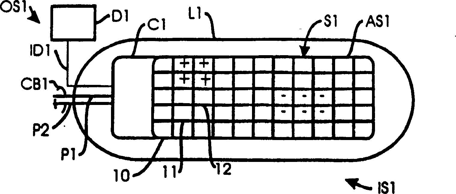
Wie in 1 gezeigt ist, enthält eine bevorzugte Form einer flachen Paddelspitze L1, die für die Implantation in einem Patienten geeignet ist, grundsätzlich eine Stimulationsbaueinheit S1, die eine Steuereinrichtung C1 enthält, und eine Matrix aus Stimulationselektroden AS1. Die Spitze L1 ist an einem Ort IS1 in einem Patienten in der Nähe von zu stimulierendem Gewebe implantiert. Die Matrix AS1 weist fünfundfünfzig Elektroden auf wie etwa flache Elektroden 10–12, die in einem rechtwinkligen Gitter angeordnet sind und voneinander elektrisch isoliert sind. Die obere Oberfläche der Matrix AS1 liegt gegenüber dem Patientengewebe an der Oberfläche der Spitze L1 frei bzw. ist diesem ausgesetzt. Die Steuereinrichtung C1 ist mit einem Leiter ID1 verbunden, über den Daten von einer Datenquelle D1 bereitgestellt werden, sowie mit einem Kabel CB1 verbunden, das Leistungsleiter P1 und P2 zum Leiten eines Stimulationsstroms an die Elektrodenmatrix AS1 enthält. P1 und P2 sind mit einer nicht gezeigten Leistungsquelle verbunden. Die Steuereinrichtung C1 ist mit jeder Elektrode in der Elektrodenmatrix AS1 über getrennte Leitungsdrähte gekoppelt. Die Datenquelle D1 befindet sich an einem Ort OS1, der sich in der Leistungsquelle oder an einem anderen Ort, gewöhnlich subkutan, befinden könnte. Die Datenquelle kann ein Mikroprozessor sein, der einen Speicher zum Speichern von Daten aufweist, die die zu aktivierenden Elektroden und deren Polaritäten identifizieren.As in 1 1, a preferred form of flat paddle tip L1 suitable for implantation in a patient basically includes a stimulation assembly S1 containing a controller C1 and a matrix of stimulation electrodes AS1. The tip L1 is implanted at a location IS1 in a patient in the vicinity of tissue to be stimulated. The matrix AS1 has fifty-five electrodes, such as flat electrodes 10-12, arranged in a rectangular grid and electrically isolated from each other. The upper surface of the matrix AS1 is exposed to the surface of the tip L1 and is exposed to the patient tissue. The controller C1 is connected to a conductor ID1, via which data from a data source D1 are provided, as well as to a cable CB1, which includes power conductors P1 and P2 for conducting a stimulation current to the electrode matrix AS1. P1 and P2 are connected to a power source, not shown. The control device C1 is coupled to each electrode in the electrode matrix AS1 via separate lead wires. The data source D1 is located at a location OS1 that may be in the power source or elsewhere, usually subcutaneously. The data source may be a microprocessor having a memory for storing data identifying the electrodes to be activated and their polarities.

Die Ausführungsform nach 1 ist besonders gut für rote Skelettmuskeln geeignet, da die Stimulation an einem solchen Muskel nur die direkt unter der Katode befindlichen Muskelfasern aktivieren kann. Aktionspotentiale verteilen sich nicht von Muskelfaser zu Muskelfaser, wie dies bei glatten Muskeln oder Herzmuskeln der Fall ist. Daher ist eine breite Matrix aus Katoden nützlich, um viele Fasern eines roten Muskels zu rekrutieren bzw. wiederherzustellen.The embodiment according to 1 is particularly well-suited for red skeletal muscles, since stimulation of such a muscle can activate only the muscle fibers directly under the cathode. Action potentials do not spread from muscle fiber to muscle fiber, as is the case with smooth muscle or cardiac muscle. Therefore, a broad matrix of cathodes is useful for recruiting many fibers of a red muscle.

Wie in 2 gezeigt ist, kann eine Spitze L1 optional auch eine weitere Matrix aus Stimulationselektroden AS2 enthalten, die Elektroden wie etwa 15–17 enthält und auf einer Seite der Spitze L1 angeordnet ist. Die Oberfläche der Elektroden in der Matrix AS2 liegt auf der Seite der Spitze L1 frei, um Gewebe eines Patienten an der Stelle IS1 elektrisch zu stimulieren. Die Elektroden in der Matrix AS2 können durch C1 und/oder durch eine getrennte Steuereinrichtung C2 wie gezeigt gesteuert werden.As in 2 Optionally, a tip L1 may optionally also include another matrix of stimulation electrodes AS2 containing electrodes such as 15-17 and disposed on one side of the tip L1. The surface of the electrodes in the matrix AS2 is exposed on the side of the tip L1 to electrically stimulate tissue of a patient at the site IS1. The electrodes in the matrix AS2 may be controlled by C1 and / or by a separate controller C2 as shown.

Wie in 1 gezeigt ist, ist jede Elektrode in der Matrix AS1 und AS2 mit der Steuereinrichtung C1 und/oder C2 über Leitungsdrähte verbunden. Ein Signal wird zur Steuereinrichtung C1 und/oder C2 über den Leiter ID1 geschickt, das die zu aktivierenden Elektroden identifiziert. Die Steuereinrichtungen C1 und C2 wirken als Schaltgatter, die Leistungsleitungen P1 und P2 zu den aktivierten Elektroden in der Matrix AS1 und AS2 durchschalten. Einige aktivierte Elektroden können zu Katoden (–) werden, während andere Elektroden zu Anoden (+) werden können. Die Pluszeichen und die Minuszeichen in 1 bezeichnen Elektroden, die als Anoden (+) bzw. als Katoden (–) aktiviert worden sind. Die nicht für eine Aktivierung gewählten Elektroden sind offene Kreise oder besitzen eine hohe Impedanz. Die Anordnung von Anoden oder Katoden in der Baueinheit S1 kann vom Patienten oder anhand einer Untersuchung durch Kliniker gewählt werden, um die gewünschten Wirkungen der Stimulation, z. B. die Maximierung der Schmerzlinderung, die Minimierung der Spastizität, das Hemmen von Anfällen, das Bewirken einer Muskelkontraktion und dergleichen zu maximieren und außerdem unerwünschte Nebeneffekte zu minimieren.As in 1 is shown, each electrode in the matrix AS1 and AS2 is connected to the controller C1 and / or C2 connected via lead wires. A signal is sent to controller C1 and / or C2 via conductor ID1, which identifies the electrodes to be activated. The control devices C1 and C2 act as switching gates which connect power lines P1 and P2 to the activated electrodes in the matrix AS1 and AS2. Some activated electrodes may become cathodes (-) while other electrodes may become anodes (+). The plus sign and the minus sign in 1 designate electrodes that have been activated as anodes (+) and cathodes (-), respectively. The electrodes not selected for activation are open circuits or have a high impedance. The placement of anodes or cathodes in assembly S1 may be selected by the patient or clinician examination to provide the desired effects of stimulation, e.g. For example, maximizing pain relief, minimizing spasticity, inhibiting seizures, inducing muscle contraction, and the like, as well as minimizing undesirable side effects.

Wie weiterhin in 1 gezeigt ist, transportieren Leistungsleiter P1 und P2 den Stimulationsstrom, der notwendig ist, um das elektrisch erregbare Gewebe in der Nähe der Spitze L1 zu stimulieren. Für eine monopolare Stimulation wäre ein einziger der Leiter P1 und P2 ausreichend; für eine bipolare Stimulation sind jedoch zwei Leistungsleiter (Einzelkanal) wie etwa P1 und P2 erforderlich. Für Doppelkanal-Anwendungen können drei oder vier Leistungsleiter verwendet werden. Es könnten weniger Drähte ausreichend sein, falls das Leistungssignal im Zeitmultiplex geliefert wird.As continues in 1 is shown, power conductors P1 and P2 carry the stimulation current necessary to stimulate the electrically excitable tissue near the tip L1. For a monopolar stimulation, a single one of the conductors P1 and P2 would be sufficient; however, bipolar pacing requires two power channels (single channel), such as P1 and P2. For dual-channel applications, three or four power conductors can be used. Fewer wires could be sufficient if the power signal is supplied in time division multiplex.

9 zeigt eine Ausführung der vorliegenden Erfindung mit zwei Leitern, die zur Spitze L1 führen. Die Leiter P1 und ID1 von 1 sind zu einem einzigen Leiter kombiniert. Die P1- und ID1-Signale werden moduliert, wodurch der Bedarf an einem dritten Leiter reduziert wird. Die Modulation des Datensignals von ID1 und des Leistungssignals von P1 oder P2 kann durch beliebige Modulationstechniken erzielt werden, einschließlich der Amplitudenmodulation (AM), der Frequenzmodulation mit Frequenzumtastung (FSK), der Phasenumtastung (PSK), der Pulspositionstaktung und irgendeiner Kombination hiervon erzielt werden, ohne jedoch darauf beschränkt zu sein. 9 shows an embodiment of the present invention with two conductors leading to the tip L1. The conductors P1 and ID1 of 1 are combined into a single ladder. The P1 and ID1 signals are modulated, reducing the need for a third conductor. The modulation of the data signal from ID1 and the power signal from P1 or P2 can be achieved by any modulation techniques, including Amplitude Modulation (AM), Frequency Shift Keying (FSK), Phase Shift Keying (PSK), Pulse Position Timing and any combination thereof, but not limited thereto.

Wie wiederum in 1 gezeigt ist, besitzt jede der Elektroden in den Matrizen AS1 und AS2 eine Fläche von 1–6 mm2, andere Größen könnten jedoch ebenfalls verwendet werden. Typischerweise sind mehrere benachbarte Elektroden parallel verbunden, um eine kombinierte Oberfläche von 6–24 mm2 zu erhalten, andere Größen könnten jedoch auch günstig sein. Die Elektroden in den Matrizen AS1 und AS2 sind elektrisch leitend und gewöhnlich aus einem Metall wie etwa Platin oder Iridium hergestellt. In 1 sind vier Elektroden als Anoden (+) und sechs Elektroden als Katoden (–) programmiert worden.As again in 1 is shown, each of the electrodes in the arrays AS1 and AS2 has an area of 1-6 mm 2 , but other sizes could also be used. Typically, several adjacent electrodes are connected in parallel to provide a combined surface area of 6-24 mm 2 , but other sizes could be beneficial. The electrodes in the arrays AS1 and AS2 are electrically conductive and usually made of a metal such as platinum or iridium. In 1 For example, four electrodes have been programmed as anodes (+) and six electrodes as cathodes (-).

Die Erfindung ist nützlich in Verbindung mit elektrisch erregbarem Gewebe, das sowohl Nervengewebe als auch Muskelgewebe umfaßt. Nervengewebe enthält periphere Nerven, die Rückenmarksoberfläche, das tiefe Rückenmark, tiefes Gehirngewebe und Gehirnoberflächengewebe. Muskelgewebe enthält (rote) Skelettmuskeln, (weiße) glatte unwillkürliche Muskeln und Herzmuskeln.The Invention is useful in conjunction with electrically excitable tissue that is both nervous tissue as well as muscle tissue. Contains nervous tissue peripheral nerves, the spinal cord surface, the deep spinal cord, deep brain tissue and brain surface tissue. Muscle tissue contains (red) Skeletal muscles, (white) smooth involuntary Muscles and heart muscles.

3 zeigt eine bevorzugte Form einer Aufzeichnungsbaueinheit R1, die eine Steuereinrichtung C2 und eine Matrix aus Aufzeichnungselektroden RE1–RE5 enthält, die elektrisch voneinander isoliert sind. Die Baueinheit R1 ist in einen Patienten an der Stelle IS2 implantiert. Die Steuereinrichtung C2 ist mit einem Leiter ID2 zur Datenübertragung und mit einem Kabel CB2, das Leistungsleiter P3 und P4 enthält, sowie mit einem zusätzlichen Leiter RD1, der aufgezeichnete und verstärkte Gewebepotentiale überträgt, die von einem oder mehreren der Leiter RE1–RE5 empfangen werden, versehen. Der Leiter RD1 kann aus fünf getrennten Leitern bestehen, die mit den Elektroden RE1–RE5 verbunden sind, oder aus einem einzigen Leiter, auf dem Potentiale von den Elektroden RE1–RE5 durch Zeitmultiplextechniken, die von der Steuereinrichtung C2 ausgeführt werden, übertragen werden. Alternativ könnte die Steuereinrichtung C2 Kombinationen der Elektroden RE1–RE5 als Stimulationselektroden aktivieren, um eine Stimulation von Gewebe zu schaffen. 3 shows a preferred form of a recording assembly R1, which includes a controller C2 and a matrix of recording electrodes RE1-RE5, which are electrically isolated from each other. The assembly R1 is implanted in a patient at the location IS2. The controller C2 is provided with a conductor ID2 for data transmission and with a cable CB2 containing power conductors P3 and P4 as well as an additional conductor RD1 which transmits recorded and amplified tissue potentials received from one or more of the conductors RE1-RE5. Mistake. The conductor RD1 may consist of five separate conductors connected to the electrodes RE1-RE5 or a single conductor on which potentials from the electrodes RE1-RE5 are transferred by time-division multiplexing techniques performed by the controller C2. Alternatively, the controller C2 could activate combinations of the electrodes RE1-RE5 as stimulation electrodes to provide stimulation of tissue.

Die Aufzeichnungsbaueinheit R1 kann für die Aufzeichnung von Potentialen in elektrisch erregbarem Gewebe verwendet werden. Die Steuereinrichtung C2 wählt von den Aufzeichnungselektroden RE1–RE5 aus, verstärkt die von den Aufzeichnungselektroden empfangenen Signale und schickt die verstärkten Signale über den Leiter RD1 zu einem Aufzeichnungsinstrument RC1. Die Steuereinrichtung C2 könnte die Signale auch Filterung oder anderweitig verarbeiten. Das Instrument RC1 befindet sich an einem anderen Ort, möglicherweise OS1.The Recording unit R1 can be used for recording potentials be used in electrically excitable tissue. The control device C2 chooses from the recording electrodes RE1-RE5, amplifies the received signals from the recording electrodes and sends the amplified Signals over the conductor RD1 to a recording instrument RC1. The control device C2 could the signals also filter or otherwise process. The instrument RC1 is in a different location, possibly OS1.

Wie in 3 gezeigt ist, befindet sich unter jeder Aufzeichnungselektrode RE1–RE5 eine elektrische Schaltung, die einen Operationsverstärker und eine Gatterschaltung enthält, um die Aufzeichnungselektrode durchzuschalten und zu trennen. Eine Aufzeichnungselektrode kann mit einer optimalen Signalstärke und mit Unterscheidung des interessierenden Potentials gewählt werden. Zwei oder mehr Elektroden können parallelgeschaltet sein, um die Impedanz abzusenken, oder können differentiell verwendet werden, um das aufgezeichnete Potential besser zu formen und Rauschsignale zu entfernen. Alternativ kann die Steuereinrichtung C2 alle Signalkonditionierungsfunktionen und Gatterschaltungen steuern, insbesondere dann, wenn die Abmessungen der Aufzeichnungsbaueinheit R1 klein sind.As in 3 is shown below each recording electrode RE1-RE5 is an electrical circuit which includes an operational amplifier and a gate circuit to turn on and off the recording electrode. A recording electrode can be chosen with optimum signal strength and potential of interest discrimination. Two or more electrodes may be connected in parallel to lower the impedance or may be used differentially to better record the recorded potential to shape and remove noise signals. Alternatively, the controller C2 may control all signal conditioning functions and gate circuits, particularly if the dimensions of the recording device R1 are small.

Der Leiter ID2 wird für den Transport von Daten von einer Datenquelle wie etwa D1 zur Steuereinrichtung C2 verwendet. Als Antwort auf die Daten aktiviert die Steuereinrichtung C2 die gewünschten Elektroden und stellt die Verstärkung ein. Das Kabel CB2 wird verwendet, um der Steuereinrichtung C2 Leistung zuzuführen. Der Leiter RD1 tritt aus der Aufzeichnungsstelle IC2 aus, um die verstärkten aufgezeichneten Potentiale der Aufzeichnungseinrichtung RC1 zuzuführen. Die Aufzeichnungselektroden können typischerweise jeweils eine Impedanz zwischen 100000 Ohm und 1,5 Megaohm besitzen, andere Impedanzen könnten jedoch wünschenswert sein.Of the Head ID2 is for the transport of data from a data source such as D1 to the controller C2 used. In response to the data, the controller activates C2 the desired electrodes and provides the reinforcement one. The cable CB2 is used to power the controller C2 supply. The conductor RD1 exits from the recording station IC2 to supply the increased recorded potentials of the recording device RC1 supply. The Recording electrodes can typically each have an impedance between 100,000 ohms and 1.5 However, other impedances may be desirable be.

Die 4 und 5 zeigen die Flexibilität von Steuereinrichtungen und Matrizen aus Stimulationselektroden sowie optionale Aufzeichnungselektroden, die gemäß der Erfindung hergestellt sind. Wie in 4 gezeigt ist, kann eine Spitze L2 eine Stimulationsbaueinheit S1 und eine optionale Aufzeichnungsbaueinheit R1 sowie zusätzliche Stimulationsbaueinheiten S2 und S3, die mit der Baueinheit S1 völlig übereinstimmen können, enthalten. Es können weitere Stimulations- oder Aufzeichnungsbaueinheiten vom Arzt während der Implantation zu S1 hinzugefügt werden. Der Leiter RD2 transportiert aufgezeichnete Potentiale an eine Aufzeichnungseinrichtung wie etwa RC1, die in 3 gezeigt ist. Der Leiter RD2 kann eine Verlängerung des Leiters RD1 sein oder kann zusätzliche Daten enthalten, die sich aus der in der Steuereinrichtung C1 der Baueinheit S1 erfolgten Verarbeitung ergeben. Für die in 4 gezeigte Konfiguration kann die Steuereinrichtung C1 der Baueinheit S1 die Funktionen der Steuereinrichtungen C1 und C2, die in Verbindung mit den 1 und 3 beschrieben worden sind, enthalten. Alternativ können Steuereinrichtungen C4 und C5 eine Steuerung der Baueinheiten S2 bzw. S3 schaffen. Die Leistung wird an die Baueinheiten S2 und S3 durch Leistungsleiter P1 und P2 geliefert. Ein Leiter ID3 tauscht die Daten aus, die für die Identifizierung der Stimulationselektroden in der Baueinheit S2, die aktiviert werden sollen, notwendig sind. Eine ähnliche Funktion wird für die Baueinheit S3 durch einen Datenleiter ID4 ausgeführt. Die Steuereinrichtung C1 verarbeitet die Daten am Leiter ID1, um die geeigneten Daten für die Baueinheiten S2 und S3 zu schaffen, die über Leiter ID3 bzw. ID4 übertragen werden. Bei einer Modulation der Leistungssignale auf den Leitern P1 und P2 könnten die Datenleiter ID1, ID3 und ID4 unnötig sein.The 4 and 5 show the flexibility of control means and matrices of stimulation electrodes as well as optional recording electrodes made according to the invention. As in 4 2, a tip L2 may include a stimulation assembly S1 and an optional recording assembly R1, as well as additional stimulus assemblies S2 and S3, which may be wholly identical to the assembly S1. Additional stimulation or recording units may be added by the physician during implantation to S1. The conductor RD2 carries recorded potentials to a recording device such as RC1 included in 3 is shown. The conductor RD2 may be an extension of the conductor RD1 or may contain additional data resulting from the processing performed in the controller C1 of the assembly S1. For the in 4 As shown, the control unit C1 of the unit S1 can perform the functions of the control units C1 and C2, which are used in conjunction with the 1 and 3 have been described. Alternatively, controllers C4 and C5 may provide control of the units S2 and S3, respectively. The power is supplied to the units S2 and S3 through power conductors P1 and P2. A conductor ID3 exchanges the data necessary for the identification of the stimulation electrodes in the unit S2 to be activated. A similar function is performed for the unit S3 through a data conductor ID4. The controller C1 processes the data on the conductor ID1 to provide the appropriate data for the units S2 and S3, which are transmitted via conductors ID3 and ID4, respectively. With a modulation of the power signals on the conductors P1 and P2, the data conductors ID1, ID3 and ID4 could be unnecessary.

Wie in 5 gezeigt ist, trägt eine Spitze L3 eine Steuereinrichtung C3, die mit der Matrix AS1 und mit einer völlig gleichen Matrix AS2 sowie mit einer Matrix AR1 verbunden ist. Jede der Aufzeichnungselektroden in der Matrix AR1 ist mit der Steuereinrichtung C3 durch einen der Leiter RL1–RL5 verbunden. Jede der Stimulationselektroden der Baueinheit AS1 ist mit der Steuereinrichtung C3 durch ein Kabel CB6 verbunden, das einzelne Leiter enthält, die getrennt mit jeder der Elektroden in der Baueinheit AS1 verbunden sind. Ebenso ist jede der Stimulationselektroden in der Baueinheit AS2 mit der Steuereinrichtung C3 über ein Kabel CB7 verbunden. Die Steuereinrichtung C3 empfängt Informationen auf dem Leiter ID1, die die Elektroden der Baueinheiten AS1 und AS2, die aktiviert werden sollen, sowie die Polaritäten der Elektroden identifizieren. Die Steuereinrichtung C3 aktiviert die Elektroden in den Baueinheiten AS1 und AS2 in der gleichen Weise wie in Verbindung mit der Steuereinrichtung C1 von 1 beschrieben.As in 5 is shown, a tip L3 carries a control device C3, which is connected to the matrix AS1 and to a completely identical matrix AS2 and to a matrix AR1. Each of the recording electrodes in the array AR1 is connected to the controller C3 through one of the conductors RL1-RL5. Each of the stimulation electrodes of the assembly AS1 is connected to the controller C3 through a cable CB6 containing individual conductors which are separately connected to each of the electrodes in the assembly AS1. Likewise, each of the stimulation electrodes in the assembly AS2 is connected to the controller C3 via a cable CB7. The controller C3 receives information on the conductor ID1 identifying the electrodes of the packages AS1 and AS2 to be activated and the polarities of the electrodes. The control device C3 activates the electrodes in the assemblies AS1 and AS2 in the same way as in connection with the control device C1 of FIG 1 described.

Die von jedem der Leiter RL1–RL5 übertragenen Potentiale werden von der Steuereinrichtung C3 auf einer Zeitmultiplexbasis über den Ausgangsleiter RD2 übertragen. RD2 kann mit einer Aufzeichnungseinrichtung wie etwa RC1 wie in 3 gezeigt verbunden sein.The potentials transferred from each of the conductors RL1-RL5 are transmitted by the controller C3 on a time-division basis via the output conductor RD2. RD2 may be connected to a recording device such as RC1 as in 3 be shown connected.

6 zeigt eine im allgemeinen zylindrische Spitze L4, die eine Steuereinrichtung C4 und eine Baueinheit aus zweiundzwanzig Stimulationselektroden AS3 einschließlich zylindrischer Elektroden 20 und 21, die wie gezeigt angeordnet sind, trägt. Im Körper der Spitze L4 sind entsprechende elektrische Schaltungen CT1 und CT2 vorhanden, die direkt an den Elektroden 20 und 21 angebracht sind (7 und 8). Für die Stimulationsbaueinheit AS3 sind die Schaltungen CT1 und CT2 elektrische Schalter oder Gatter, die spezifizierte Elektroden in der Baueinheit in Übereinstimmung mit den auf dem Leiter ID1 empfangenen Daten aktivieren. Falls an jeder longitudinalen Position der Spitze nur eine einzige Elektrode vorhanden ist, könnte es sich um eine Ringelektrode handeln. Falls an jeder longitudinalen Position mehrere Elektroden vorhanden sind, könnten die Elektroden an jeder longitudinalen Position gleiche Sektoren des Querschnitts der Spitze L4 einnehmen. Dann könnten unter Verwendung der Steuereinrichtung C4 nur jene Elektroden, die sich am nächsten am erregbaren Gewebe befinden, für die Stimulation oder Aufzeichnung verwendet werden. Im Operationssaal kann eine komplexe Spitze zusammengefügt werden, indem eine beliebige Anzahl zylindrischer Verlängerungen auf die Spitze L4 gesteckt wird (6). 6 Figure 11 shows a generally cylindrical tip L4 comprising a controller C4 and a unit of twenty-two stimulation electrodes AS3 including cylindrical electrodes 20 and 21 , which are arranged as shown, carries. In the body of the tip L4 there are corresponding electrical circuits CT1 and CT2 which are directly connected to the electrodes 20 and 21 are attached ( 7 and 8th ). For stimulation assembly AS3, circuits CT1 and CT2 are electrical switches or gates that activate specified electrodes in the package in accordance with the data received on conductor ID1. If there is only a single electrode at each longitudinal position of the tip, it could be a ring electrode. If there are multiple electrodes at each longitudinal position, the electrodes at each longitudinal position could occupy equal sectors of the cross section of the tip L4. Then, using the controller C4, only those electrodes closest to the excitable tissue could be used for stimulation or recording. In the operating room, a complex tip can be put together by putting any number of cylindrical extensions on the tip L4 ( 6 ).

Eine Aufzeichnungsbaueinheit kann in der gleichen Form wie die Baueinheit AS3, die in 6 gezeigt ist, hergestellt werden. In diesem Fall würden die Elektroden die gleiche Aufzeichnungsfunktion wie in Verbindung mit 3 beschrieben ausführen. In einer solchen Ausführung würden die Schaltungen CT1 und CT2 ein Verstärker und ein schaltbares Gatter sein, das ein Gewebepotential an die Steuereinrichtung C4 übertragen würde.A recording unit may be in the same shape as the unit AS3 used in 6 is shown to be produced. In this case, the electrodes would have the same recording function as in conjunction with 3 describe described. In In such an embodiment, the circuits CT1 and CT2 would be an amplifier and a switchable gate which would transmit tissue potential to the controller C4.

10 ist eine Draufsicht einer weiteren Ausführung der Erfindung, die mehrere Steuereinrichtungen verwendet, wovon jede eine oder mehrere der Stimulationselektroden in der Matrix steuert. 10 veranschaulicht eine Spitze L5 mit einer Stimulationsbaueinheit S5, die eine Matrix aus Steuereinrichtungen (nicht gezeigt) und eine entsprechende Matrix aus Stimulationselektroden AS5 enthält. Die Leistungsleiter P1 und P2 und das Datensignal ID1 sind mit der Spitze L1 ähnlich wie in 1 verbunden. Alternativ kann der Leistungsleiter P1, wie in 12 gezeigt ist, mit dem Datenleiter ID1 unter Verwendung irgendeiner Anzahl von Modulationstechniken moduliert werden, wodurch die Anzahl der Leiter zur Spitze L5 reduziert wird. 10 Figure 4 is a plan view of another embodiment of the invention employing multiple controllers, each controlling one or more of the stimulation electrodes in the matrix. 10 FIG. 10 illustrates a tip L5 with a stimulation assembly S5 that includes a matrix of controllers (not shown) and a corresponding matrix of stimulation electrodes AS5. The power conductors P1 and P2 and the data signal ID1 are similar to the tip L1 as in FIG 1 connected. Alternatively, the power conductor P1, as in FIG 12 is shown to be modulated with the data conductor ID1 using any number of modulation techniques, thereby reducing the number of conductors to the tip L5.

Wie in 10 gezeigt ist, besitzt jede Stimulationselektrode in der Matrix AS5 eine entsprechende Steuereinrichtung, die den Betrieb dieser Elektrode steuert. Leistungssignale P1 und P2 sowie das Datensignal ID1 werden für jede dieser einzelnen Steuereinrichtungen bereitgestellt, die ihrerseits den Betrieb der zugeordneten Stimulationselektroden anhand dieser Signale steuern. In einer solchen Ausführung wäre die Steuereinrichtung C1 (wie in 1 gezeigt) nicht erforderlich. 11 ist eine explosionsartige Seitenansicht einer einzelnen Steuereinrichtung C5 und der zugeordneten Stimulationselektrode E5 der Spitze L5. Leistungsleitungen P1 und P2 sowie die Datenleitung ID1 verlaufen zu jeder Steuereinrichtung in der Spitze L5 einschließlich der Steuereinrichtung C5. Alternativ kann, wie in 13 gezeigt ist, der Leistungsleiter P1 mit dem Datenleiter ID1 unter Verwendung irgendeiner Anzahl von Modulationstechniken moduliert werden, wodurch die Anzahl von Leitern zur Spitzen-Steuereinrichtung C5 reduziert wird. 11 stellt eine typische Elektroden/Steuereinrichtungspaar-Kombination der Spitze 5 dar. Die Steuereinrichtung C5 kann eine integrierte Schaltung (IC) sein, ferner können die zur Steuereinrichtung C5 führenden Leiter an der Steuereinrichtung C5 drahtgebondet sein. Jedes Elektroden/Steuereinrichtungspaar besitzt eine eindeutige Adresse, so daß der Datenleiter ID1 anhand der über den Datenleiter ID1 transportierten Adresseninformationen angeben kann, welche Elektroden aktiviert werden sollen. Für jede für die Aktivierung bezeichnete Elektrode wird die Elektrode als eine Anode (+) oder als eine Katode (–) bezeichnet. In einer weiteren Ausführung kann die Steuereinrichtung C5 so positioniert sein, daß der Betrieb einer Anzahl von Elektroden gesteuert wird. Die Steuereinrichtung C5 kann auch für die Steuerung von Aufzeichnungselektroden verwendet werden.As in 10 is shown, each stimulation electrode in the matrix AS5 has a corresponding control device which controls the operation of this electrode. Power signals P1 and P2 and the data signal ID1 are provided for each of these individual controllers, which in turn control the operation of the associated stimulation electrodes from these signals. In such an embodiment, the controller C1 (as in FIG 1 not shown). 11 is an exploded side view of a single controller C5 and the associated stimulation electrode E5 of the tip L5. Power lines P1 and P2 and the data line ID1 extend to each controller in the peak L5 including the controller C5. Alternatively, as in 13 1, the power conductor P1 is modulated with the data conductor ID1 using any number of modulation techniques, thereby reducing the number of conductors to the peak control device C5. 11 represents a typical electrode / controller pair combination of the tip 5 The control device C5 can be an integrated circuit (IC), furthermore the conductors leading to the control device C5 can be wire-bonded to the control device C5. Each electrode / controller pair has a unique address so that the data conductor ID1 can indicate which electrodes to activate based on the address information carried over the data conductor ID1. For each electrode designated for activation, the electrode is referred to as an anode (+) or a cathode (-). In another embodiment, the controller C5 may be positioned to control the operation of a number of electrodes. The controller C5 may also be used for the control of recording electrodes.

Jede der Baueinheiten AS1–AS3, AS5 und AR1 kann ein Siliciumwafer und daher starr sein. Die Steuereinrichtungen C1–C5 können herkömmliche Mikrosteuereinrichtungen sein, die in einem Speicher gespeicherte Befehle ausführen können. Andere Teile der Spitzen L1–L5, etwa die Baueinheiten AS1, AS2 und AR1 von 5, können flexibel und inert sein oder flexibel sein und Drähte tragen. Die Verwendung von flexiblen elektrischen Schaltungen oder Bandkabeln könnte ebenfalls vorteilhaft sein.Each of the assemblies AS1-AS3, AS5 and AR1 may be a silicon wafer and therefore rigid. The controllers C1-C5 may be conventional microcontrollers that can execute instructions stored in a memory. Other parts of the tips L1-L5, such as the units AS1, AS2 and AR1 of 5 , can be flexible and inert or flexible and wear wires. The use of flexible electrical circuits or ribbon cables could also be advantageous.

Die Spitzen L1 bis L5 bieten gegenüber bekannten Spitzen mehrere Vorteile. Vor der Implantation ist nicht immer bekannt, was die beste Strategie für die Spitzenanordnung und die Elektrodenpolarität ist. Die Spitzen L1–L5 ermöglichen eine spätere Ausführung der Wahl und eine zusätzliche Umprogrammierung zu späteren Zeitpunkten, so daß die Elektrodenposition Freiheitsgrade erhält. Es ist manchmal nützlich, auf einer Leitung fünf oder mehr Elektroden zu haben (insbesondere quer zur Rückenmarksachse), so daß zwei oder drei an bevorzugten medialen/lateralen Positionen gewählt werden können. Die bevorzugten Ausführungen ermöglichen Änderungen des effektiven Stimulationsbereichs nach der Implantation lediglich durch Programmierung.The Tips L1 to L5 offer known tips several advantages. Before implantation is not always known what the best strategy for the top arrangement and the electrode polarity is. The tips L1-L5 enable a later one execution the election and an additional one Reprogramming to later Times, so that the Electrode position degrees of freedom receives. It is sometimes useful on a lead five or to have more electrodes (in particular transversely to the spinal cord axis), so that two or three at preferred medial / lateral positions can. The preferred versions allow changes to the effective stimulation area after implantation only through programming.

Eine wesentliche Notwendigkeit für Ärzte, die eine Rückenmarksstimulation verwenden, ist die Positionierung einer oder mehrerer Elektroden auf der "physiologischen Mittellinie". Das bedeutet, daß Impulse Gleichgewichtseffekte ergeben und nicht von der einen oder der anderen Seite (in der Nähe der einen oder der anderen Spinalwurzel) übermäßig vorgespannt werden. Wenn der Ort des Vertebralkanals für die Spitzenanordnung genutzt wird, ist in nur 27% der Zeit die Parästhesie ausgeglichen (Barolat, G., Zeme, S. und Ketcik, B., Multifactorial analysis of epidural spinal cord stimulation, Stereotact, Funct. Neurosurg., 56 (1991) 77–103). Die bevorzugten Ausführungen ermöglichen, daß die "physiologische Mittellinie" durch Prüfen gefunden und entsprechend programmiert wird.A essential need for doctors who a spinal cord stimulation use, is the positioning of one or more electrodes on the "physiological Centerline " means that pulses Balance effects, not one or the other Page (near the one or the other spinal root) are over-biased. If the location of the vertebral canal for the tip assembly is used in just 27% of the time the paresthesia balanced (Barolat, G., Zeme, S. and Ketcik, B., Multifactorial analysis of epidural spinal cord stimulation, Stereotact, Funct. Neurosurg., 56 (1991) 77-103). The preferred versions enable, that the "physiological midline" found by testing and programmed accordingly.

Die Aufzeichnung elektrischer Signale ist sehr schwierig und hängt stark vom Abstand vom aktiven Gewebe, von der Richtung der Aktionspotentiale in Axonen und insbesondere von der Fläche/Impedanz der Aufzeichnungsstelle (eine niedrige Impedanz nimmt Potentiale von größeren Abständen auf, die Signale sind jedoch klein) ab. Durch Aussuchen der richtigen Orte von Aufzeichnungsstellen und durch Addieren oder Subtrahieren von Signalen benachbarter Stellen kann das beste Signal erhalten werden.The Recording electrical signals is very difficult and depends heavily the distance from the active tissue, the direction of the action potentials in axons and in particular the area / impedance of the recording site (A low impedance picks up potentials from longer distances, which are signals but small). By selecting the right places from recording locations and adding or subtracting signals from adjacent locations the best signal can be obtained.

Die Fähigkeit, Elektroden aus einer großen Anzahl von möglichen Orten zu wählen und zu aktivieren, die durch die bevorzugten Ausführungen geschaffen wird, ist in dem Fall wertvoll, in dem irgendeine Stelle aufgrund mechanischer/elektrischer Probleme, vernarbten Gewebes und dergleichen nicht benutzbar ist. Eine nahe benachbarte Stelle könnte ein nahezu ebenso brauchbares Ergebnis liefern.The ability to select and activate electrodes from a large number of possible locations provided by the preferred embodiments is valuable in the case where ir A site is not usable due to mechanical / electrical problems, scarred tissue and the like. A nearby location could provide a nearly equally useful result.

Derzeit ist der einzige Weg zum Wählen optimaler Elektrodenorte (neben der Wahl der Polaritäten) die chirurgische Positionierung der Spitze, die mit der Zeit unzuverlässig werden könnte, da die Positionierung bei einer bestimmten Körperhaltung des Patienten erfolgte und sich durch Migration der Spitze verändern kann. Es sind Vorschläge für Spitzen gemacht worden, die ihre Konfiguration ändern können, diese Vorschläge bieten jedoch nicht den Vorteil der bevorzugten Ausführungen.Currently is the only way to vote optimal electrode locations (besides the choice of polarities) the surgical positioning of the tip, which become unreliable over time could, because the positioning was carried out at a certain posture of the patient and can change through migration of the top. There are suggestions for tips made who have changed their configuration can, these suggestions however, do not offer the advantage of the preferred embodiments.

Die vorteilhaften Anwendungen von Spitzen L1–L5, die in dieser Beschreibung beschrieben worden sind, umfassen Anordnungen:

  • a. über oder in dem motorischen Cortex oder in der Kleinhirnrinde, wo somatotopische Karten des Körpers vorhanden sind und wo eine Feinsteuerung der Orte der Erregung zu einer Beeinflussung der Bewegungen oder einer Kontrolle der verschiedenen Körperteile beitragen kann;
  • b. über oder in dem sensorischen Cortex, für den ebenfalls eine somatotopische Karte vorhanden ist, so daß die Parästhesie und/oder motorische Effekte für spezifische Körperteile eingestellt werden können;
  • c. im Thalamus, wo eine dreidimensionale Körperkarte vorhanden ist und wo Lamina aus Zellen vorhanden sind, die am besten unter Verwendung vieler Kontakte und einer Programmierung aktiviert (oder teilweise aktiviert) werden könnten;
  • d. im tiefen Gewebe, wo eine Stimulation vorteilhaft durch zylindrische Spitzen erzielt wird;
  • e. quer oder über der Cauda Equina (Nerven im Spinalkanal, der von der Spitze der Chorda abfällt), um eine große Selektivität der Stimulation zu ermöglichen;
  • f. in der Cochlea, wo ein unzureichender Raum für viele Drähte vorhanden ist, jedoch viele Kanäle erforderlich sind und eine Feinabstimmung, welche Stellen längs der Cochlea stimuliert werden, zu einem besseren Hören führen können;
  • g. über Zweige motorischer Nerven oder großer Nerven, um unterschiedliche Faserbündel zu aktivieren; und
  • h. in der Retina, wo in dem Fall, in dem bei einem Patienten kein Licht auf die Rückseite des Auges trifft, die bevorzugte Ausführung neurale bzw. neuronale bzw. neuronale Muster stimulieren, könnte, als ob Licht fokussiert hindurchginge und wahrgenommen würde.
The advantageous applications of tips L1-L5 described in this specification include arrangements:
  • a. over or in the motor cortex or in the cerebellar cortex where somatotopic maps of the body are present and where fine control of the sites of arousal may contribute to influencing the movements or control of the various body parts;
  • b. over or in the sensory cortex for which there is also a somatotopic map so that paresthesia and / or motor effects can be adjusted for specific body parts;
  • c. in the thalamus, where there is a three-dimensional body map and where there are laminae of cells that could best be activated (or partially activated) using many contacts and programming;
  • d. in deep tissue, where stimulation is advantageously achieved by cylindrical tips;
  • e. across or over the cauda equina (nerves in the spinal canal that descend from the apex of the chorda) to allow for high selectivity of stimulation;
  • f. in the cochlea, where there is insufficient space for many wires, but many channels are required, and fine-tuning which sites are stimulated along the cochlea may result in better hearing;
  • G. via branches of motor nerves or large nerves to activate different fiber bundles; and
  • H. in the retina, where in the case where no light hits the back of the eye in a patient, the preferred embodiment would stimulate neural or neuronal patterns, as if light were focused and perceived.

Die Steuereinrichtungschips, die in dieser Beschreibung offenbart wurden, sind vorzugsweise starr und auf Silikon mit einer hermetisch dichten Abdeckung hergestellt. Sie können jedoch sehr klein sein. Alle anderen Teile der Spitzen L1–L5 können flexibel sein.The Controller chips disclosed in this specification are preferably rigid and on silicone with a hermetically sealed Cover made. You can but be very small. All other parts of the tips L1-L5 can be flexible be.

Ein weiterer Vorteil der Spitzen L1–L5 besteht darin, daß die Anzahl von Aufzeichnungsstellen parallel zur Bildung einer Stimulationsstelle, die im allgemeinen eine niedrige Impedanz und eine größere Oberfläche erfordert, programmiert werden könnten. Es können mehrere Stimulationsstellen programmiert werden, um die Impedanz zu reduzieren.One Another advantage of the tips L1-L5 is that the Number of recording sites parallel to the formation of a stimulation site, which generally requires low impedance and larger surface area, could be programmed. It can several pacing sites are programmed to match the impedance to reduce.

Fachleute erkennen, daß die bevorzugten Ausführungen geändert und abgewandelt werden können, ohne vom Erfindungsgedanken und vom Umfang der Erfindung, der in den beigefügten Ansprüchen definiert ist, abzuweichen. Beispielsweise können die Elektroden eben sein oder irgendeine Form (z. B. rund, oval und rechtwinklig) besitzen. Die Elektroden können auch eine dreidimensionale äußere Oberfläche (z. B. zylindrisch, sphärisch, halbsphärisch oder konisch) besitzen.professionals recognize that the preferred embodiments changed and can be modified without departing from the spirit and scope of the invention, which is incorporated in the attached claims is defined to depart. For example, the electrodes may be flat or have any shape (eg, round, oval, and rectangular). The electrodes can also a three-dimensional outer surface (z. Cylindrical, spherical, hemispherical or conical).

Claims (15)

Vorrichtung für eine Wechselwirkung mit elektrisch erregbarem Gewebe eines Patienten, mit: einer Gruppe implantierbarer Elektroden, die so beschaffen sind, daß sie mit dem Gewebe in Wechselwirkung treten, wobei die Gruppe von Elektroden wenigstens auf einer implantierbaren Sonde oder Spitze angeordnet ist, um wenigstens eine Matrix zu bilden, wobei jede Elektrode wenigstens an eine andere der Elektroden angrenzt oder zu einer anderen Elektrode benachbart ist; einem Hauptkabel, das wenigstens einen Leistungsleiter enthält, der so beschaffen ist, daß er sich zu einem Ort in der Nähe eines Gewebes erstreckt, wobei die Anzahl der Leistungsleiter geringer als die Anzahl der Elektroden ist; einer Datenquelle; einem Datenleiter, der so beschaffen ist, daß er sich von der Datenquelle an den Ort in der Nähe des Gewebes erstreckt; und einer implantierbaren Steuereinrichtung, die mit der Datenquelle in Verbindung steht und ansprechend auf die Daten ist, um wenigstens ein Paar nicht benachbarter Elektroden in der Gruppe zu dem Hauptkabel durchzuschalten, um eine Anoden- und Katoden-Beziehung zwischen dem Paar nicht benachbarter Elektroden herzustellen, wobei die implantierbare Steuereinrichtung als eine Matrix aus Steuereinrichtungen ausgebildet ist, wobei jede Steuereinrichtung eine oder mehrere Elektroden der Elektrodenmatrix steuert, wobei die Spitze eine Stimulationsbaueinheit (S5) aufweist, die die Matrix aus Steuereinrichtungen und eine korrespondierende Matrix aus Elektroden (AS5) aufweist und wobei jede Steuereinrichtung mit einer Elektrode baulich integriert ist.Device for an interaction with electrically excitable tissue of a patient, With: a group of implantable electrodes that do so they are interact with the tissue, the group of electrodes arranged at least on an implantable probe or tip is to form at least one matrix, each electrode at least adjacent to another of the electrodes or adjacent to another electrode is; a main cable, the at least one power conductor contains which is such that he to a place nearby a fabric extends, wherein the number of power conductors less as the number of electrodes is; a data source; one Data ladder designed to be detached from the data source to the place nearby extends the tissue; and an implantable controller, which is connected to the data source and appealing to the data is at least one pair of non-adjacent electrodes in the group to the main cable to an anode and cathode relationship between the pair of non-adjacent electrodes, in which the implantable controller as a matrix of controllers is formed, each control device one or more Electrodes of the electrode matrix controls, wherein the tip of a Stimulationsbaueinheit (S5) comprising the matrix of controllers and a corresponding one Matrix of electrodes (AS5) and wherein each control device is structurally integrated with an electrode. Vorrichtung nach Anspruch 1, wobei die Gruppe von Elektroden Stimulationselektroden zum Stimulieren des Gewebes aufweist.The device of claim 1, wherein the group of Electrode has stimulation electrodes for stimulating the tissue. Vorrichtung nach Anspruch 1, wobei die Gruppe von Elektroden Aufzeichnungselektroden zum Leiten von Potentialen, die im Gewebe festgestellt wurden, aufweist.The device of claim 1, wherein the group of Electrode recording electrodes for conducting potentials, the were detected in the tissue. Vorrichtung nach Anspruch 3, wobei die Aufzeichnungselektroden parallelgeschaltet sind, um wenigstens eine Stimulation8elektrode zu bilden.Apparatus according to claim 3, wherein the recording electrodes are connected in parallel to at least one stimulation 8elektrode to build. Vorrichtung nach Anspruch 1, wobei die Datenquelle an einem Ort, der von dem an das Gewebe angrenzenden Ort entfernt ist, Adaptionen oder Anpassungen aufweist und wobei der Datenleiter Adaptionen zur Erstreckung von dem entfernten Ort zu dem an das Gewebe angrenzenden Ort aufweist.Apparatus according to claim 1, wherein the data source at a location away from the site adjacent to the tissue is, has adaptations or adjustments and where the data conductor Adaptions to the extension from the remote location to the Tissue has adjacent site. Vorrichtung nach Anspruch 1, wobei die Steuereinrichtung eine Gruppe schaltbarer Gatter aufweist, die das Hauptkabel mit wenigstens einer ausgewählten Elektrode verbinden.Apparatus according to claim 1, wherein the control means a group of switchable gate having the main cable with at least one selected Connect the electrode. Vorrichtung nach Anspruch 1, wobei die Steuereinrichtung eine Gruppe aus wenigstens einer integrierten Schaltung enthält, wobei jede der integrierten Schaltungen in der Gruppe das Hauptkabel mit der wenigstens einen Elektrode verbinden kann.Apparatus according to claim 1, wherein the control means includes a group of at least one integrated circuit, wherein each of the integrated circuits in the group the main cable with the can connect at least one electrode. Vorrichtung nach Anspruch 1, wobei die Gruppe implantierbarer Elektroden eine erste Anzahl von stimulierenden Elektroden zum Stimulieren des Gewebes und eine zweite Anzahl von Aufzeichnungselektroden zum Leiten von Potentialen im Gewebe enthält, wobei das Hauptkabel einen Leistungsleiter und einen Aufzeichnungsleiter enthält, wobei die Datenquelle eine erste Quelle enthält, die wenigstens eine der Stimulationselektroden und wenigstens eine der Aufzeichnungselektroden identifiziert, und wobei die Steuereinrichtung eine Einrichtung zum Durchschalten der gewählten wenigstens einen Stimulationselektrode zum Leistungsleiter und zum Durchschalten der gewählten wenigstens einen Aufzeichnungselektrode zum Aufzeichnungsleiter enthält.The device of claim 1, wherein the group is implantable Electrodes a first number of stimulating electrodes for stimulation of the tissue and a second number of recording electrodes for Conducting potentials in the tissue contains, with the main cable a Power conductor and a recording conductor contains, wherein the data source contains a first source containing at least one of Stimulation electrodes and at least one of the recording electrodes identified, and wherein the control means comprises means to switch through the selected at least one stimulation electrode to the power conductor and to Switching through the selected at least one recording electrode to the recording conductor contains. Vorrichtung nach Anspruch 8, wobei die Steuereinrichtung eine Multiplexereinrichtung zum Übertragen von Signalen zwischen der wenigstens einen Aufzeichnungselektrode und dem Aufzeichnungsleiter im Zeitmultiplex enthält.Apparatus according to claim 8, wherein the control means a multiplexer device for transmitting of signals between the at least one recording electrode and the recording conductor in time division multiplex. Vorrichtung nach Anspruch 8, wobei die erste Anzahl von Stimulationselektroden eine erste Matrix aus Stimulationselektroden und eine von der ersten Matrix beabstandete zweite Matrix aus Stimulationselektroden enthält, wobei die erste Matrix mit der Steuereinrichtung durch ein erstes Kabel verbunden ist und die zweite Matrix mit der Steuereinrichtung durch ein zweites Kabel verbunden ist.Apparatus according to claim 8, wherein the first number of stimulation electrodes, a first matrix of stimulation electrodes and a second array of stimulation electrodes spaced from the first matrix contains wherein the first matrix with the control means by a first Cable is connected and the second matrix with the control device through a second cable is connected. Vorrichtung nach Anspruch 8, ferner mit einer dritten Anzahl von Stimulationselektroden, die von der ersten Anzahl von Stimulationselektroden beabstandet ist, und einer zweiten Steuereinrichtung, die versetzt zu der Steuereinrichtung angeordnet ist, um die dritte Anzahl von Stimulationselektroden durchzuschalten, wobei die Steuereinrichtung und die zweite Steuereinrichtung durch ein zweites Hauptkabel verbunden sind.Apparatus according to claim 8, further comprising a third Number of stimulation electrodes, from the first number of Pacing electrodes is spaced, and a second control device, which is arranged offset to the control device to the third Number of stimulation electrodes through, the control device and the second control device connected by a second main cable are. Vorrichtung nach Anspruch 1, wobei die implantierbare Steuereinrichtung ferner so beschaffen ist, daß sie eine erste Anzahl benachbarter Elektroden zum Hauptkabel durchschalten kann, damit sie gemeinsam eine erste kombinierte Elektrode bilden, die so beschaffen ist, daß sie in der Anoden- und Katoden-Beziehung mit wenigstens einer Elektrode in der Gruppe zusammenwirkt.The device of claim 1, wherein the implantable Control device is further arranged so that it has a first number of adjacent Switch electrodes to the main cable to allow them to work together form a first combined electrode that is so that she in the anode and cathode relationship with at least one electrode interacts in the group. Vorrichtung nach Anspruch 12, wobei die implantierbare Steuereinrichtung ferner so beschaffen ist, daß sie eine zweite Zahl benachbarter Elektroden zum Hauptkabel durchschaltet, damit sie gemeinsam eine zweite kombinierte Elektrode bilden, die so beschaffen ist, daß sie in der Anoden- und Katoden-Beziehung mit der ersten kombinierten Elektrode zusammenwirkt.The device of claim 12, wherein the implantable Control device is further arranged so that it has a second number of adjacent Switches electrodes to the main cable, so they together a forming a second combined electrode arranged to be in the anode and cathode relationship cooperates with the first combined electrode. Vorrichtung nach Anspruch 1, wobei die Gruppe implantierbarer Elektroden eine erste Anzahl von Stimulationselektroden enthält wobei die erste Anzahl der Stimulationselektroden eine erste Matrix aus Stimulationselektroden und eine von der ersten Matrix beabstandete zweite Matrix von Stimulationselektroden aufweist, wobei die erste Matrix mit der Steuereinrichtung über ein erstes Kabel verbunden ist und die zweite Matrix mit der Steuereinrichtung über ein zweites Kabel verbunden ist.The device of claim 1, wherein the group is implantable Electrodes containing a first number of stimulation electrodes the first number of stimulation electrodes form a first matrix Stimulation electrodes and one spaced from the first matrix second matrix of stimulation electrodes, wherein the first Matrix is connected to the control device via a first cable and the second matrix is connected to the controller via a second cable is. Vorrichtung für eine Wechselwirkung mit elektrisch erregbarem Gewebe eines Patienten, mit: einer Gruppe implantierbarer Elektroden, die so beschaffen sind, daß sie mit dem Gewebe in Wechselwirkung treten, wobei die Gruppe von Elektroden auf wenigstens einer implantierbaren Spitze angeordnet ist, um wenigstens eine Matrix zu bilden, wobei jede Elektrode wenigstens an eine andere der Elektroden angrenzt oder zu einer anderen Elektrode benachbart ist; einem Hauptkabel, das so beschaffen ist, daß es sich zu einem Ort in der Nähe des Gewebes erstreckt und wenigstens einen Leistungsleiter, einen Datenleiter und einen Multiplexer zum Koppeln wenigstens eines der Leistungsleiter und des Datenleiters aufweist, wobei die Anzahl der Leistungsleiter geringer als die Anzahl der Elektroden ist; einer Datenquelle; und einer implantierbaren Steuereinrichtung, die mit der Datenquelle in Verbindung steht und ansprechend auf die Daten ist, um wenigstens ein Paar nicht benachbarter Elektroden in der Gruppe zum Hauptkabel durchzuschalten, um eine Anoden- und Katoden-Beziehung zwischen dem Paar nicht benachbarter Elektroden herzustellen, wobei die implantierbare Steuereinrichtung als eine Matrix aus Steuereinrichtungen ausgebildet ist, wobei jede Steuereinrichtung eine oder mehrere Elektroden der Elektrodenmatrix steuert, wobei die Spitze eine Stimulationsbaueinheit (S5) aufweist, die die Matrix aus Steuereinrichtungen und eine korrespondierende Matrix aus Elektroden (AS5) aufweist und wobei jede Steuereinrichtung mit einer Elektrode baulich integriert ist.An apparatus for interacting with electrically excitable tissue of a patient, comprising: a set of implantable electrodes adapted to interact with the tissue, the array of electrodes disposed on at least one implantable tip to at least one matrix each electrode being at least adjacent to or adjacent to another electrode; a trunk cable adapted to extend to a location near the fabric and having at least one power conductor, a data conductor, and a multiplexer for coupling at least one of the power conductors and the data conductor, wherein the number of power conductors is less than the number the electrodes is; a data source; and an implantable controller associated with the Data source is in communication and responsive to the data, to turn on at least a pair of non-adjacent electrodes in the group to the main cable to establish an anode and cathode relationship between the pair of non-adjacent electrodes, wherein the implantable control device as a matrix of control devices wherein each control device controls one or more electrodes of the electrode matrix, the tip having a stimulation unit (S5) comprising the matrix of control means and a corresponding matrix of electrodes (AS5), and each control means being structurally integrated with an electrode.
DE1999128552 1999-06-22 1999-06-22 Device for interacting with electrically excitable tissue of a patient Expired - Fee Related DE19928552B4 (en)

Priority Applications (1)

Application Number Priority Date Filing Date Title
DE1999128552 DE19928552B4 (en) 1999-06-22 1999-06-22 Device for interacting with electrically excitable tissue of a patient

Applications Claiming Priority (1)

Application Number Priority Date Filing Date Title
DE1999128552 DE19928552B4 (en) 1999-06-22 1999-06-22 Device for interacting with electrically excitable tissue of a patient

Publications (2)

Publication Number Publication Date
DE19928552A1 DE19928552A1 (en) 2001-01-04
DE19928552B4 true DE19928552B4 (en) 2008-04-03

Family

ID=7912138

Family Applications (1)

Application Number Title Priority Date Filing Date
DE1999128552 Expired - Fee Related DE19928552B4 (en) 1999-06-22 1999-06-22 Device for interacting with electrically excitable tissue of a patient

Country Status (1)

Country Link
DE (1) DE19928552B4 (en)

Families Citing this family (1)

* Cited by examiner, † Cited by third party
Publication number Priority date Publication date Assignee Title
EP3797823B1 (en) 2019-09-24 2023-10-25 Imec VZW An electrode arrangement for stimulating and recording electrical signals in biological matter, a neural probe and a micro-electrode array

Citations (5)

* Cited by examiner, † Cited by third party
Publication number Priority date Publication date Assignee Title
US5038781A (en) * 1988-01-21 1991-08-13 Hassan Hamedi Multi-electrode neurological stimulation apparatus
US5314495A (en) * 1988-09-02 1994-05-24 The Board Of Trustees Of The Leland Stanford Junior University Microelectronic interface
US5501703A (en) * 1994-01-24 1996-03-26 Medtronic, Inc. Multichannel apparatus for epidural spinal cord stimulator
WO1997037720A1 (en) * 1996-04-04 1997-10-16 Medtronic, Inc. Living tissue stimulation and recording techniques
US5735887A (en) * 1996-12-10 1998-04-07 Exonix Corporation Closed-loop, RF-coupled implanted medical device

Patent Citations (5)

* Cited by examiner, † Cited by third party
Publication number Priority date Publication date Assignee Title
US5038781A (en) * 1988-01-21 1991-08-13 Hassan Hamedi Multi-electrode neurological stimulation apparatus
US5314495A (en) * 1988-09-02 1994-05-24 The Board Of Trustees Of The Leland Stanford Junior University Microelectronic interface
US5501703A (en) * 1994-01-24 1996-03-26 Medtronic, Inc. Multichannel apparatus for epidural spinal cord stimulator
WO1997037720A1 (en) * 1996-04-04 1997-10-16 Medtronic, Inc. Living tissue stimulation and recording techniques
US5735887A (en) * 1996-12-10 1998-04-07 Exonix Corporation Closed-loop, RF-coupled implanted medical device

Non-Patent Citations (2)

* Cited by examiner, † Cited by third party
Title
T.A. Frieswijk, W.L.C. Rutten, "Three-dimensional neuroelectronic interface for peripheral nerve stimulation [...]", Proc. 16<SUP>th</SUP> Ann. Int. Conf. IEEE, 1994, S. 808-809 *
T.A. Frieswijk, W.L.C. Rutten, "Three-dimensional neuroelectronic interface for peripheral nerve stimulation [...]", Proc. 16th Ann. Int. Conf. IEEE, 1994, S. 808-809

Also Published As

Publication number Publication date
DE19928552A1 (en) 2001-01-04

Similar Documents

Publication Publication Date Title
DE60214752T2 (en) MULTIPLEXED CONTROL UNIT FOR ELECTRODE MATRICES
US6038480A (en) Living tissue stimulation and recording techniques with local control of active sites
DE60124021T2 (en) Implantable stimulation lead
DE60035602T2 (en) LINE TO STIMULATE THE SPINE
DE602005002498T2 (en) brain implant
US6473653B1 (en) Selective activation of electrodes within an inplantable lead
DE69836589T2 (en) IMPLANTABLE TWO-CHANNEL NEUROSTIMULATOR
DE69535658T2 (en) Multi-channel device for irritating the epidural spine
DE69837481T2 (en) DEVICE FOR ADJUSTING THE STIMULATION LOCATION OF ELECTRICALLY IRRITABLE TISSUE
DE60023784T2 (en) System for the selective activation of brain neurons, spinal cord saving or peripheral nerves
EP1062969B1 (en) Electrode assembly
DE60207216T2 (en) CABLE WITH ANGLE AND SPACE POSITION ADJUSTABLE BETWEEN ELECTRODES
DE60123889T2 (en) Electronic multichannel circuitry for tissue stimulator
US5713922A (en) Techniques for adjusting the locus of excitation of neural tissue in the spinal cord or brain
EP0928212B1 (en) Flexible artificial nerve plate
US20020111661A1 (en) Multiple electrode lead body for spinal cord stimulation
DE102015017269B3 (en) Electronic stimulation system and device thereof for spinal ganglion
DE112009001510T5 (en) Method for electronically stimulating tissue of a patient by moving a stimulation site and system for using the same
DE69722782T2 (en) DEVICE FOR STIMULATING LIVING TISSUE AND RELEVANT RECORDING
DE10294019B4 (en) Neurostimulator and data transmission method
DE19928552B4 (en) Device for interacting with electrically excitable tissue of a patient
DE10033400A1 (en) Electrical stimulation system for medical therapy selectively connects near, central and far electrodes to provide anode reference terminal for cathode pulses
DE60203863T2 (en) X and Y selectable line units

Legal Events

Date Code Title Description
8110 Request for examination paragraph 44
8125 Change of the main classification

Ipc: A61N 1/05

8364 No opposition during term of opposition
8328 Change in the person/name/address of the agent

Representative=s name: KUDLEK & GRUNERT PATENTANWAELTE PARTNERSCHAFT, 803

R119 Application deemed withdrawn, or ip right lapsed, due to non-payment of renewal fee

Effective date: 20120103