DE202011000036U1 - Plant for a miter saw - Google Patents
Plant for a miter saw Download PDFInfo
- Publication number
- DE202011000036U1 DE202011000036U1 DE202011000036U DE202011000036U DE202011000036U1 DE 202011000036 U1 DE202011000036 U1 DE 202011000036U1 DE 202011000036 U DE202011000036 U DE 202011000036U DE 202011000036 U DE202011000036 U DE 202011000036U DE 202011000036 U1 DE202011000036 U1 DE 202011000036U1
- Authority
- DE
- Germany
- Prior art keywords
- miter saw
- abutment
- plant
- workpiece
- support surface
- Prior art date
- Legal status (The legal status is an assumption and is not a legal conclusion. Google has not performed a legal analysis and makes no representation as to the accuracy of the status listed.)
- Expired - Lifetime
Links
Images
Classifications
-
- B—PERFORMING OPERATIONS; TRANSPORTING
- B27—WORKING OR PRESERVING WOOD OR SIMILAR MATERIAL; NAILING OR STAPLING MACHINES IN GENERAL
- B27B—SAWS FOR WOOD OR SIMILAR MATERIAL; COMPONENTS OR ACCESSORIES THEREFOR
- B27B27/00—Guide fences or stops for timber in saw mills or sawing machines; Measuring equipment thereon
- B27B27/08—Guide fences or stops for timber in saw mills or sawing machines; Measuring equipment thereon arranged adjustably, not limited to only one of the groups B27B27/02 - B27B27/06
-
- B—PERFORMING OPERATIONS; TRANSPORTING
- B23—MACHINE TOOLS; METAL-WORKING NOT OTHERWISE PROVIDED FOR
- B23D—PLANING; SLOTTING; SHEARING; BROACHING; SAWING; FILING; SCRAPING; LIKE OPERATIONS FOR WORKING METAL BY REMOVING MATERIAL, NOT OTHERWISE PROVIDED FOR
- B23D47/00—Sawing machines or sawing devices working with circular saw blades, characterised only by constructional features of particular parts
- B23D47/04—Sawing machines or sawing devices working with circular saw blades, characterised only by constructional features of particular parts of devices for feeding, positioning, clamping, or rotating work
-
- B—PERFORMING OPERATIONS; TRANSPORTING
- B27—WORKING OR PRESERVING WOOD OR SIMILAR MATERIAL; NAILING OR STAPLING MACHINES IN GENERAL
- B27B—SAWS FOR WOOD OR SIMILAR MATERIAL; COMPONENTS OR ACCESSORIES THEREFOR
- B27B27/00—Guide fences or stops for timber in saw mills or sawing machines; Measuring equipment thereon
- B27B27/04—Guide fences or stops for timber in saw mills or sawing machines; Measuring equipment thereon arranged perpendicularly to the plane of the saw blade
-
- B—PERFORMING OPERATIONS; TRANSPORTING
- B27—WORKING OR PRESERVING WOOD OR SIMILAR MATERIAL; NAILING OR STAPLING MACHINES IN GENERAL
- B27B—SAWS FOR WOOD OR SIMILAR MATERIAL; COMPONENTS OR ACCESSORIES THEREFOR
- B27B27/00—Guide fences or stops for timber in saw mills or sawing machines; Measuring equipment thereon
- B27B27/06—Guide fences or stops for timber in saw mills or sawing machines; Measuring equipment thereon arranged angularly with respect to the plane of the saw blade, e.g. for mitring
-
- B—PERFORMING OPERATIONS; TRANSPORTING
- B27—WORKING OR PRESERVING WOOD OR SIMILAR MATERIAL; NAILING OR STAPLING MACHINES IN GENERAL
- B27B—SAWS FOR WOOD OR SIMILAR MATERIAL; COMPONENTS OR ACCESSORIES THEREFOR
- B27B27/00—Guide fences or stops for timber in saw mills or sawing machines; Measuring equipment thereon
- B27B27/10—Devices for moving or adjusting the guide fences or stops
-
- Y—GENERAL TAGGING OF NEW TECHNOLOGICAL DEVELOPMENTS; GENERAL TAGGING OF CROSS-SECTIONAL TECHNOLOGIES SPANNING OVER SEVERAL SECTIONS OF THE IPC; TECHNICAL SUBJECTS COVERED BY FORMER USPC CROSS-REFERENCE ART COLLECTIONS [XRACs] AND DIGESTS
- Y10—TECHNICAL SUBJECTS COVERED BY FORMER USPC
- Y10T—TECHNICAL SUBJECTS COVERED BY FORMER US CLASSIFICATION
- Y10T83/00—Cutting
- Y10T83/748—With work immobilizer
- Y10T83/7593—Work-stop abutment
- Y10T83/7607—Normal to plane of cut
- Y10T83/7613—Adjustable
- Y10T83/762—Angularly relative to plane of cut; e.g., miter
-
- Y—GENERAL TAGGING OF NEW TECHNOLOGICAL DEVELOPMENTS; GENERAL TAGGING OF CROSS-SECTIONAL TECHNOLOGIES SPANNING OVER SEVERAL SECTIONS OF THE IPC; TECHNICAL SUBJECTS COVERED BY FORMER USPC CROSS-REFERENCE ART COLLECTIONS [XRACs] AND DIGESTS
- Y10—TECHNICAL SUBJECTS COVERED BY FORMER USPC
- Y10T—TECHNICAL SUBJECTS COVERED BY FORMER US CLASSIFICATION
- Y10T83/00—Cutting
- Y10T83/748—With work immobilizer
- Y10T83/7593—Work-stop abutment
- Y10T83/7647—Adjustable
-
- Y—GENERAL TAGGING OF NEW TECHNOLOGICAL DEVELOPMENTS; GENERAL TAGGING OF CROSS-SECTIONAL TECHNOLOGIES SPANNING OVER SEVERAL SECTIONS OF THE IPC; TECHNICAL SUBJECTS COVERED BY FORMER USPC CROSS-REFERENCE ART COLLECTIONS [XRACs] AND DIGESTS
- Y10—TECHNICAL SUBJECTS COVERED BY FORMER USPC
- Y10T—TECHNICAL SUBJECTS COVERED BY FORMER US CLASSIFICATION
- Y10T83/00—Cutting
- Y10T83/768—Rotatable disc tool pair or tool and carrier
- Y10T83/7684—With means to support work relative to tool[s]
- Y10T83/7693—Tool moved relative to work-support during cutting
- Y10T83/7697—Tool angularly adjustable relative to work-support
-
- Y—GENERAL TAGGING OF NEW TECHNOLOGICAL DEVELOPMENTS; GENERAL TAGGING OF CROSS-SECTIONAL TECHNOLOGIES SPANNING OVER SEVERAL SECTIONS OF THE IPC; TECHNICAL SUBJECTS COVERED BY FORMER USPC CROSS-REFERENCE ART COLLECTIONS [XRACs] AND DIGESTS
- Y10—TECHNICAL SUBJECTS COVERED BY FORMER USPC
- Y10T—TECHNICAL SUBJECTS COVERED BY FORMER US CLASSIFICATION
- Y10T83/00—Cutting
- Y10T83/768—Rotatable disc tool pair or tool and carrier
- Y10T83/7684—With means to support work relative to tool[s]
- Y10T83/7722—Support and tool relatively adjustable
-
- Y—GENERAL TAGGING OF NEW TECHNOLOGICAL DEVELOPMENTS; GENERAL TAGGING OF CROSS-SECTIONAL TECHNOLOGIES SPANNING OVER SEVERAL SECTIONS OF THE IPC; TECHNICAL SUBJECTS COVERED BY FORMER USPC CROSS-REFERENCE ART COLLECTIONS [XRACs] AND DIGESTS
- Y10—TECHNICAL SUBJECTS COVERED BY FORMER USPC
- Y10T—TECHNICAL SUBJECTS COVERED BY FORMER US CLASSIFICATION
- Y10T83/00—Cutting
- Y10T83/768—Rotatable disc tool pair or tool and carrier
- Y10T83/7755—Carrier for rotatable tool movable during cutting
- Y10T83/7763—Tool carrier reciprocable rectilinearly
- Y10T83/7768—With means to adjust path of reciprocation
- Y10T83/7772—Angular relative to previous path
Landscapes
- Life Sciences & Earth Sciences (AREA)
- Engineering & Computer Science (AREA)
- Mechanical Engineering (AREA)
- Wood Science & Technology (AREA)
- Forests & Forestry (AREA)
- Sawing (AREA)
Abstract
Anlage für eine Gehrungssäge, die an einem Werkzeugrumpf zum Stützen eines Werkstücks montiert ist, umfassend: mindestens eine obere Anlage, die eine bewegliche Anlage mit einer oberen Stützfläche für das Werkstück ist; und mindestens eine untere Anlage, die eine untere Stützfläche für das Werkstück aufweist; wobei die untere Anlage ebenfalls eine bewegliche Anlage ist und zwischen einer ersten Stützposition und einer zweiten Stützposition beweglich ist; und wobei die untere Stützfläche und die obere Stützfläche in der selben Ebene liegen, wenn sich die untere Anlage an der ersten oder zweiten Stützposition befindet, und die untere Stützfläche und die obere Stützfläche in unterschiedlichen Ebenen liegen, wenn sich die untere Anlage an einer Position befindet, die zwischen der ersten und zweiten Stützposition liegt.A system for a miter saw mounted on a tool body for supporting a workpiece, comprising: at least one upper structure which is a movable structure having an upper support surface for the workpiece; and at least one lower support which has a lower support surface for the workpiece; wherein the lower plant is also a movable plant and is movable between a first support position and a second support position; and wherein the lower support surface and the upper support surface lie in the same plane when the lower abutment is in the first or second support position, and the lower support surface and the upper support surface lie in different planes when the lower abutment is in one position , which is between the first and second support position.
Description
Informationen zu in Zusammenhang stehender AnmeldungInformation related to the application
Diese Anmeldung beansprucht die Prioritätsrechte der
Hintergrundbackground
Diese Offenbarung betrifft allgemein Gehrungssägen und insbesondere eine Anlagevorrichtung für eine Gehrungssäge.This disclosure relates generally to miter saws, and more particularly to a miter saw attachment system.
Gehrungssägen werden zur Zeit unter verschiedenen Bedingungen zum Schneiden eines Werkstücks benutzt. Dazu kann der Bediener das Sägeblatt optional in eine beliebige von verschiedenen Stellungen oder in eine beliebige von verschiedenen Betriebsarten bringen, um einen vertikalen Schnitt, einen Winkelschnitt, einen Schrägschnitt oder einen kombinierten Gehrungsschnitt auszuführen.Miter saws are currently used under various conditions for cutting a workpiece. To do this, the operator may optionally place the saw blade in any of various positions or in any of various modes of operation to perform a vertical cut, an angle cut, a bevel cut, or a combined miter cut.
Wie einzusehen ist, enthalten Gehrungssägen im Allgemeinen eine Basis, einen drehbar mit der Basis verbundenen Arbeitstisch, eine Anlagebaugruppe zum Stützen eines Werkstücks und einen schwenkbar mit dem Arbeitstisch verbundenen Sägemechanismus. Übliche Anlagen weisen im Allgemeinen eine von zwei Formen auf, nämlich eine feststehende Anlage oder eine bewegliche Anlage.As can be appreciated, miter saws generally include a base, a work table pivotally connected to the base, a plant assembly for supporting a workpiece, and a saw mechanism pivotally connected to the work table. Conventional plants generally have one of two forms, namely a fixed installation or a movable installation.
Der Rumpfteil und die Funktionen einer feststehenden Anlage werden durch ein einziges Element erhalten.The body part and the functions of a fixed installation are obtained by a single element.
Eine bewegliche Anlage enthält im Allgemeinen eine an der Basis befestigte untere Anlage und eine bewegliche obere Anlage, die beweglich an der unteren Anlage montiert ist. Die Stützflächen der unteren und der oberen Anlage der beweglichen Anlage liegen in der selben Ebene, um zusammen als Stütze für das Werkstück zu fungieren. Die Anlage weist eine Ebene „A” zum Stützen des Werkstücks auf. Die Ebene „A” muss vertikal zur Arbeitsfläche des Arbeitstisches liegen, und die Ebene „A” der beweglichen Anlage wird zusammen durch die endgültig justierten Stützflächen der unteren und der oberen Anlage erhalten und definiert.A mobile system generally includes a lower attachment fixed to the base and a movable upper attachment movably mounted to the lower attachment. The support surfaces of the lower and upper plant of the mobile plant are in the same plane to act together as a support for the workpiece. The system has a plane "A" for supporting the workpiece. The plane "A" must be vertical to the working surface of the worktable, and the plane "A" of the movable system shall be obtained and defined together by the final adjusted support surfaces of the lower and upper system.
Beim Ausführen eines Gehrungsschnitts kann der Benutzer die bewegliche Anlage zur äußeren Seite der Gehrungssäge bewegen, um zu verhindern, dass der Sägemechanismus die bewegliche Anlage beeinträchtigt. Die obere Anlage bekannter Vorrichtungen kann daher als bewegliche Anlage in verschiedenen Formen angeordnet sein:
- 1. Eine besondere Führungsnut, die parallel zu den Stützflächen der Anlage liegt, ist zwischen der oberen und der unteren Anlage angeordnet, und die Beeinträchtigung, die sich aus einer Gehrungsschnittarbeit der Gehrungssäge ergibt, kann vermieden werden, indem die bewegliche Anlage entlang der Führungsnut bewegt wird;
- 2. die obere und die untere Anlage sind aneinander angelenkt, wobei sich die bewegliche Anlage bezüglich der feststehenden Anlage drehen kann, wobei die Achse der Drehbewegung vertikal zu den Stützflächen der Anlagen steht, und die Beeinträchtigung, die sich aus der Gehrungsschnittarbeit der Gehrungssäge ergibt, kann vermieden werden, indem verschiedene Positionen nach dem Drehen der beweglichen Anlage erzeugt werden;
- 3. die obere und die untere Anlage sind aneinander angelenkt, wobei sich die obere Anlage bezüglich der feststehenden Anlage drehen kann, wobei die Achse der Drehbewegung vertikal zu den Stützflächen der Anlagen steht, und die Beeinträchtigung, die sich aus der Gehrungsschnittarbeit der Gehrungssäge ergibt, kann vermieden werden, indem verschiedene Positionen nach dem Drehen der oberen Anlage erzeugt werden; oder
- 4. die obere Anlage weist allgemein mindestens zwei Positionierungsstift auf, wobei die untere Anlage eine Vielzahl von Positionierungslöchern aufweist, wobei die Richtungen der Achsen der Stifte und Löcher parallel zu den Stützflächen stehen, und die Beeinträchtigung, die sich aus der Gehrungsschnittarbeit der Gehrungssäge ergibt, kann vermieden werden, da die verschiedenen Zusammenwirkungspositionen der Stifte mit den Positionierungslöchern verschiedene Positionen der oberen Anlage erzeugen können.
- 1. A special guide groove, which is parallel to the bearing surfaces of the plant, is disposed between the upper and lower plant, and the interference resulting from a miter cutting operation of the miter saw can be avoided by moving the movable plant along the guide groove becomes;
- 2. the upper and lower equipment are articulated to each other, the movable equipment being able to rotate relative to the fixed equipment, the axis of rotation being vertical to the support surfaces of the equipment, and the deterioration resulting from the miter cutting of the miter saw, can be avoided by generating different positions after rotating the mobile plant;
- 3. the upper and lower equipment are hinged together, the upper equipment being able to rotate relative to the fixed equipment, the axis of rotation being vertical to the support surfaces of the equipment, and the deterioration resulting from the miter cutting of the miter saw, can be avoided by creating different positions after turning the upper plant; or
- 4. the upper plant generally has at least two locating pins, the lower plant having a plurality of locating holes, the directions of the axes of the pins and holes being parallel to the supporting faces, and the deterioration resulting from the miter cutting of the miter saw; can be avoided since the different positions of cooperation of the pins with the positioning holes can produce different positions of the upper abutment.
Da die untere Anlage in solchen bekannten Vorrichtungen im Allgemeinen eine feststehende Anlage ist, weist die Gehrungssäge noch einige Mängel auf. Zum Beispiel ist in der Sicherheitsnorm vorgesehen, dass der Abstand zwischen der Stützfläche der Anlagevorrichtung und dem Sägeblatt so klein wie möglich sein sollte, um zu verhindern, dass das Werkstück beim Schneiden kleinerer Werkstücke herausfliegt. Im Hinblick auf den kleineren Abstand zwischen der feststehenden Anlage und dem Sägeblatt, der zur Beeinträchtigung bei einer Gehrungsschnittarbeit führen kann, kann die bekannte Anlagevorrichtung die durch die Sicherheitsnorm vorgesehenen Anforderungen nicht erfüllen. Um dieses Problem zu lösen, offenbart ein USamerikanisches Patent Nr.
Die vorliegende Gehrungssäge soll die nach dem Stand der Technik bestehenden Mängel überwinden, indem sie eine verbesserte Gehrungssäge mit einer verbesserten Anlagevorrichtung vorsieht, die einen einfachen Aufbau aufweist und bequem bedient werden kann.The present miter saw is intended to overcome the shortcomings of the prior art by providing an improved miter saw with an improved abutment which is simple in construction and convenient to operate.
Dazu ist an der vorliegenden Gehrungssäge eine Anlage vorgesehen, die an einem Werkzeugrumpf zum Stützen eines Werkstücks montiert ist, und die mindestens eine obere Anlage enthält, die eine bewegliche Anlage mit einer oberen Stützfläche für ein Werkstück ist, und mindestens eine untere Anlage, die ebenfalls eine bewegliche Anlage mit einer unteren Stützfläche für das Werkstück ist, wobei sich die untere Anlage mindestens zwischen einer ersten Stützposition und einer zweiten Stützposition bewegen kann, und wobei die untere Stützfläche und die obere Stützfläche in der selben Ebene liegen, wenn sich die untere Anlage an der ersten oder zweiten Stützposition befindet, und nicht in der selben Ebene sind, wenn sich die untere Anlage an einer Position zwischen der ersten und der zweiten Stützposition befindet.For this purpose, a plant is provided on the present miter saw, which is mounted on a tool body for supporting a workpiece, and which includes at least one upper plant, which is a movable plant with an upper support surface for a workpiece, and at least one lower plant, also a movable abutment with a lower support surface for the workpiece, wherein the lower abutment can move at least between a first support position and a second support position, and wherein the lower support surface and the upper support surface lie in the same plane when the lower abutment the first or second support position, and are not in the same plane when the lower abutment is located at a position between the first and the second support position.
Gemäß einer bevorzugten Ausführungsform enthält die Anlage auch einen Bügel und mindestens eine Verbindungsstange mit zwei schwenkbar mit dem Bügel bzw. der unteren Anlage verbundenen Enden.According to a preferred embodiment, the system also includes a bracket and at least one connecting rod with two ends pivotally connected to the bracket or the lower system.
Gemäß einer weiteren Ausführungsform enthält die Anlage auch einen Bügel mit mindestens zwei Öffnungen, und die untere Anlage weist mindestens einen Stift zum Zusammenwirken mit den Öffnungen auf.According to a further embodiment, the installation also includes a bracket with at least two openings, and the lower unit has at least one pin for interacting with the openings.
Die vorliegende Gehrungssäge kann außerdem eine Basis, einen Arbeitstisch, eine Anlage zum Stützen eines Werkstücks und einen Sägemechanismus enthalten, der schwenkbar mit dem Arbeitstisch verbunden ist, wobei der Sägemechanismus ein Sägeblatt zum Schneiden des Werkstücks enthält und die Anlage die obige Anlage für die Gehrungssäge ist.The present miter saw may further include a base, a work table, a support for a workpiece, and a saw mechanism pivotally connected to the work table, the saw mechanism including a saw blade for cutting the work and the installation being the above miter saw installation ,
Mit den obigen technischen Lösungen kann die vorliegende Gehrungssäge die folgenden technischen Wirkungen erreichen:
- (1) Die untere Anlage ist beweglich mit dem Bügel der Anlage verbunden, und daher können mindestens zwei Stützpositionen erhalten werden (zum Beispiel eine Position nahe beim Sägeblatt und eine Position weit weg vom Sägeblatt), um für die Anlage einen kompakten Aufbau vorzusehen, der bequem benutzt werden kann;
- (2) genügend Stützflächen können unter verschiedenen Schnittbedingungen vorgesehen sein; und
- (3) wenn sich die Gehrungssäge im vertikalen Schneidmodus befindet, kann die Anlage genügend Stützfläche vorsehen, um das zu schneidende Werkstück zu stützen, selbst wenn das Werkstück kürzer ist, daher kann sie gewährleisten, dass das Werkstück nicht herausfliegen kann, und dadurch die Sicherheit erhöhen.
- (1) The lower equipment is movably connected to the bracket of the equipment, and therefore at least two support positions can be obtained (for example, a position close to the saw blade and a position far away from the saw blade) to provide a compact structure for the equipment can be used conveniently;
- (2) enough support surfaces can be provided under different cutting conditions; and
- (3) When the miter saw is in the vertical cutting mode, the plant can provide enough support surface to support the workpiece to be cut, even if the workpiece is shorter, thus ensuring that the workpiece can not fly out, and thereby safety increase.
Kurze Beschreibung der ZeichnungenBrief description of the drawings
Genaue BeschreibungPrecise description
Bevorzugte Ausführungsformen der vorliegenden Gehrungssäge werden nun mit Bezug auf die begleitenden Zeichnungen genau beschrieben.Preferred embodiments of the present miter saw will now be described in detail with reference to the accompanying drawings.
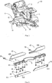
Mit Bezug auf
Wie in
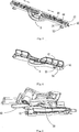
Mit Bezug auf die
Wie in den
Wie in
Der Bügel
In der vorliegend beschriebenen und dargestellten Ausführungsform kann die Gehrungssäge benutzt werden, um einen Schrägschnitt an zwei Seiten auszuführen; daher weisen die Anlagevorrichtungen an den beiden Seiten des Sägeblatts denselben Aufbau auf. In Hinblick auf eine Gehrungssäge für Schrägschnitte nur an einer Seite kann die Anlagevorrichtung nur an einer Seite des Sägeblatts montiert sein, um die Herstellungskosten zu reduzieren.In the presently described and illustrated embodiment, the miter saw can be used to make a bevel cut on two sides; Therefore, the abutment devices on the two sides of the saw blade on the same structure. With regard to a miter saw for bevel cuts on only one side, the abutment can be mounted on only one side of the saw blade to reduce manufacturing costs.
Wie in
Wie in
Die obige Beschreibung erläutert eine beispielhafte erste Ausführungsform, bei der die Anlagevorrichtung
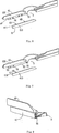
Mit Bezug auf die
Genau wie bei der beispielhaften ersten Ausführungsform können die obere Anlage
Die zweite beispielhafte Ausführungsform unterscheidet sich von der ersten beispielhaften Ausführungsform darin, dass an der unteren Anlage
Ein Fachmann wird einsehen, dass die Querschnitte des Stifts
Mit Bezug auf die
Genau wie bei der ersten beispielhaften Ausführungsform können die obere Anlage
Genauso wie bei der zweiten beispielhafte Ausführungsform ist an der unteren Anlage
Außerdem ist an dem Bügel der Anlage mit Bezug auf die
Während so beispielhafte Ausführungsformen beschrieben und dargestellt wurden, versteht sich, dass die Gehrungssäge und die Anlage, die so beschrieben und dargestellt sind, nicht gemäß den in der Zeichnung gezeigten Aufbauten eingeschränkt sein sollen. Zum Beispiel soll die Befestigungsweise zwischen der unteren Anlage und dem Bügel nicht auf die Aufbauten in den obigen Ausführungsformen beschränkt sein. Vielmehr sind beliebige Veränderungen, Ersetzungen oder Abwandlungen von Form oder Position solcher Elemente als innerhalb des Schutzumfangs der nachstehend dargelegten Ansprüche fallend zu betrachten.While such exemplary embodiments have been described and illustrated, it will be understood that the miter saw and plant so described and illustrated are not to be limited in accordance with the structures shown in the drawings. For example, the fastening manner between the lower plant and the bracket should not be limited to the structures in the above embodiments. Rather, any changes, substitutions or modifications of the form or position of such elements as within the scope of the claims set forth below.
ZITATE ENTHALTEN IN DER BESCHREIBUNG QUOTES INCLUDE IN THE DESCRIPTION
Diese Liste der vom Anmelder aufgeführten Dokumente wurde automatisiert erzeugt und ist ausschließlich zur besseren Information des Lesers aufgenommen. Die Liste ist nicht Bestandteil der deutschen Patent- bzw. Gebrauchsmusteranmeldung. Das DPMA übernimmt keinerlei Haftung für etwaige Fehler oder Auslassungen.This list of the documents listed by the applicant has been generated automatically and is included solely for the better information of the reader. The list is not part of the German patent or utility model application. The DPMA assumes no liability for any errors or omissions.
Zitierte PatentliteraturCited patent literature
- CN 201020022763 [0001] CN 201020022763 [0001]
- US 5755148 [0008] US 5755148 [0008]
Claims (16)
Applications Claiming Priority (2)
| Application Number | Priority Date | Filing Date | Title |
|---|---|---|---|
| CN201020022763.3 | 2010-01-08 | ||
| CN2010200227633U CN201659327U (en) | 2010-01-08 | 2010-01-08 | Miter saw leaning fence |
Publications (1)
| Publication Number | Publication Date |
|---|---|
| DE202011000036U1 true DE202011000036U1 (en) | 2011-05-26 |
Family
ID=43229737
Family Applications (1)
| Application Number | Title | Priority Date | Filing Date |
|---|---|---|---|
| DE202011000036U Expired - Lifetime DE202011000036U1 (en) | 2010-01-08 | 2011-01-07 | Plant for a miter saw |
Country Status (5)
| Country | Link |
|---|---|
| US (1) | US9616587B2 (en) |
| CN (1) | CN201659327U (en) |
| DE (1) | DE202011000036U1 (en) |
| FR (1) | FR2955047B3 (en) |
| GB (1) | GB2476876B (en) |
Cited By (1)
| Publication number | Priority date | Publication date | Assignee | Title |
|---|---|---|---|---|
| DE102016109377A1 (en) * | 2016-05-20 | 2017-11-23 | Festool Gmbh | Machine tool with a plant body |
Families Citing this family (14)
| Publication number | Priority date | Publication date | Assignee | Title |
|---|---|---|---|---|
| CN201659327U (en) | 2010-01-08 | 2010-12-01 | 南京德朔实业有限公司 | Miter saw leaning fence |
| DE202010000260U1 (en) * | 2010-02-26 | 2010-06-02 | Freund Maschinenfabrik Gmbh & Co. Kg | Stand-circular knife |
| TWI441701B (en) * | 2010-12-28 | 2014-06-21 | Rexon Ind Corp Ltd | A worktable for circular saw |
| CN102581375A (en) * | 2011-01-05 | 2012-07-18 | 力山工业股份有限公司 | Worktable for circular saw |
| CN102303327B (en) * | 2011-09-02 | 2014-07-30 | 南京德朔实业有限公司 | Miter saw for cutting wide plates |
| CN104511655B (en) * | 2013-09-30 | 2017-04-12 | 力山工业股份有限公司 | Sawing machine backup plate with auxiliary positioning device |
| CN104260151A (en) * | 2014-09-19 | 2015-01-07 | 上海锐奇工具股份有限公司 | Skew cutting saw with interchangeable left and right slide backing bars |
| TW201713435A (en) * | 2015-10-15 | 2017-04-16 | 力山工業股份有限公司 | Fence assembly for miter saw |
| US9849605B2 (en) * | 2016-05-28 | 2017-12-26 | Chin-Chin Chang | Power miter saw having a fence with elevated platforms |
| CN109773983A (en) * | 2017-11-13 | 2019-05-21 | 南京德朔实业有限公司 | A kind of cutting tool |
| US10940569B2 (en) | 2018-06-12 | 2021-03-09 | Tti (Macao Commercial Offshore) Limited | Miter saw |
| CN108972728B (en) * | 2018-06-21 | 2020-07-31 | 浙江诚慧模具有限公司 | Folding positioning reference plate on woodworking sawing machine |
| US10836066B2 (en) * | 2018-06-29 | 2020-11-17 | Robert James Suhling | Zero clearance fence |
| US20230085057A1 (en) * | 2021-09-15 | 2023-03-16 | Chin-Chin Chang | Mechanism for adjusting position of a removable fence of a power miter saw |
Citations (2)
| Publication number | Priority date | Publication date | Assignee | Title |
|---|---|---|---|---|
| US5755148A (en) | 1995-07-07 | 1998-05-26 | Black & Decker Inc. | Adjustable fence for a compound miter saw |
| CN201659327U (en) | 2010-01-08 | 2010-12-01 | 南京德朔实业有限公司 | Miter saw leaning fence |
Family Cites Families (18)
| Publication number | Priority date | Publication date | Assignee | Title |
|---|---|---|---|---|
| US1477065A (en) * | 1922-12-29 | 1923-12-11 | Ira J Kuert | Adjustable and interchangeable form for hollow wall construction |
| US3188161A (en) * | 1962-12-28 | 1965-06-08 | Gen Motors Corp | Vertically adjustable shelf |
| US3302669A (en) * | 1964-06-29 | 1967-02-07 | Edler Adolph | Motor powered radial arm tool support |
| JPH0518082Y2 (en) * | 1987-02-20 | 1993-05-14 | ||
| DE3831378C2 (en) * | 1988-09-15 | 1997-01-23 | Festo Kg | Stop device for table saws |
| US5063805A (en) * | 1989-11-08 | 1991-11-12 | Emerson Electric Co. | Compound miter saw |
| US5181448A (en) | 1991-12-20 | 1993-01-26 | Emerson Electric Co. | Miter saw apparatus with adjustable workpiece supporting fence |
| GB2291006A (en) | 1994-07-08 | 1996-01-17 | Milwaukee Electric Tool Corp | Reversable mitre saw fence |
| US5855366A (en) * | 1997-10-29 | 1999-01-05 | P & F Brother Industrial Corporation | Work supporting device mountable on a worktable of a circular sawing apparatus |
| JP3884865B2 (en) * | 1998-02-06 | 2007-02-21 | 株式会社マキタ | Tabletop circular saw |
| US6688350B2 (en) * | 2002-03-26 | 2004-02-10 | Waterloo Industries, Inc. | Power tool platform |
| US20030228197A1 (en) * | 2002-06-07 | 2003-12-11 | Ashot Salvaryan | Cold metal cutting machine |
| CN2744453Y (en) * | 2004-07-26 | 2005-12-07 | 苏州宝时得电动工具有限公司 | Oblique saw |
| US7882772B2 (en) * | 2004-12-15 | 2011-02-08 | Wise Robert W | Repetitive fence for cross-cutting materials |
| JP4442514B2 (en) * | 2005-05-27 | 2010-03-31 | 日立工機株式会社 | Tabletop cutting machine |
| JP5377945B2 (en) * | 2008-03-21 | 2013-12-25 | 株式会社マキタ | Tabletop cutting machine |
| BRPI0802420A2 (en) * | 2008-07-07 | 2010-03-09 | Whirlpool Sa | mechanism for moving shelves of refrigeration equipment and refrigeration equipment |
| CN201399621Y (en) * | 2009-03-30 | 2010-02-10 | 南京德朔实业有限公司 | Miter saw |
-
2010
- 2010-01-08 CN CN2010200227633U patent/CN201659327U/en not_active Expired - Lifetime
-
2011
- 2011-01-06 US US12/985,495 patent/US9616587B2/en active Active
- 2011-01-07 FR FR1150124A patent/FR2955047B3/en not_active Expired - Lifetime
- 2011-01-07 DE DE202011000036U patent/DE202011000036U1/en not_active Expired - Lifetime
- 2011-01-07 GB GB201100211A patent/GB2476876B/en active Active
Patent Citations (2)
| Publication number | Priority date | Publication date | Assignee | Title |
|---|---|---|---|---|
| US5755148A (en) | 1995-07-07 | 1998-05-26 | Black & Decker Inc. | Adjustable fence for a compound miter saw |
| CN201659327U (en) | 2010-01-08 | 2010-12-01 | 南京德朔实业有限公司 | Miter saw leaning fence |
Cited By (1)
| Publication number | Priority date | Publication date | Assignee | Title |
|---|---|---|---|---|
| DE102016109377A1 (en) * | 2016-05-20 | 2017-11-23 | Festool Gmbh | Machine tool with a plant body |
Also Published As
| Publication number | Publication date |
|---|---|
| FR2955047B3 (en) | 2012-01-13 |
| GB2476876B (en) | 2013-12-25 |
| CN201659327U (en) | 2010-12-01 |
| GB2476876A (en) | 2011-07-13 |
| FR2955047A3 (en) | 2011-07-15 |
| GB201100211D0 (en) | 2011-02-23 |
| US9616587B2 (en) | 2017-04-11 |
| US20110167977A1 (en) | 2011-07-14 |
Similar Documents
| Publication | Publication Date | Title |
|---|---|---|
| DE202011000036U1 (en) | Plant for a miter saw | |
| AT506486B1 (en) | TENSION DEVICE FOR A COMPUTER-CONTROLLED, SPANISH MACHINING MACHINE | |
| EP0022122B1 (en) | Bending machine | |
| DE1910977B2 (en) | VICE DEVICE, ESPECIALLY FOR PORTABLE WORKBENCHES | |
| DE2915288C2 (en) | Cold circular saw with a swiveling saw blade arm | |
| DE102011001811A1 (en) | chair | |
| DE3413047A1 (en) | MEASURING DEVICE | |
| DE202012105077U1 (en) | Cutting depth setting mechanism for power tools | |
| DE602006000299T2 (en) | Cutting table for metal sheets | |
| EP2747929B1 (en) | Tool for processing work pieces | |
| DE10217570B4 (en) | In the cutting direction movable trimming table and woodworking machine with a Besäumtisch | |
| DE3002665C2 (en) | Laser beam knife manipulator | |
| DE19743149A1 (en) | Machine tool | |
| DE102015205444B4 (en) | Positioning system of workpieces to be machined and machine equipped with such system | |
| CH623875A5 (en) | ||
| DE102016220447A1 (en) | Electric cutting machine | |
| DE2421895C3 (en) | Auxiliary device for do-it-yourself machines for performing milling and rebating work, in particular for producing elongated holes | |
| DE703861C (en) | Hand tool for deburring round or oval ones | |
| DE10208071B4 (en) | Rip fence device for a saw table | |
| DE2332921C2 (en) | Stop device | |
| DE3912460C2 (en) | ||
| AT210715B (en) | Sheet metal working machine or the like, in particular guillotine shears or press brake | |
| DE2609546C2 (en) | Device for cutting off the nozzle pipes or connecting them to a wind nozzle | |
| DE102015103028A1 (en) | tile cutter | |
| AT209137B (en) | Clamping device for machine tools |
Legal Events
| Date | Code | Title | Description |
|---|---|---|---|
| R207 | Utility model specification |
Effective date: 20110630 |
|
| R150 | Utility model maintained after payment of first maintenance fee after three years |
Effective date: 20140122 |
|
| R151 | Utility model maintained after payment of second maintenance fee after six years | ||
| R158 | Lapse of ip right after 8 years |