EP0002103A1 - A blood cell counter having a purging system - Google Patents
A blood cell counter having a purging system Download PDFInfo
- Publication number
- EP0002103A1 EP0002103A1 EP19780300472 EP78300472A EP0002103A1 EP 0002103 A1 EP0002103 A1 EP 0002103A1 EP 19780300472 EP19780300472 EP 19780300472 EP 78300472 A EP78300472 A EP 78300472A EP 0002103 A1 EP0002103 A1 EP 0002103A1
- Authority
- EP
- European Patent Office
- Prior art keywords
- aperture
- conduit
- gap
- blood cell
- cell counter
- Prior art date
- Legal status (The legal status is an assumption and is not a legal conclusion. Google has not performed a legal analysis and makes no representation as to the accuracy of the status listed.)
- Granted
Links
- 238000010926 purge Methods 0.000 title claims abstract description 47
- 210000000601 blood cell Anatomy 0.000 title claims abstract description 32
- 239000007788 liquid Substances 0.000 claims abstract description 13
- 210000004027 cell Anatomy 0.000 claims abstract description 5
- 239000012530 fluid Substances 0.000 claims description 13
- 238000004891 communication Methods 0.000 claims description 9
- 239000010437 gem Substances 0.000 claims description 9
- 229910001751 gemstone Inorganic materials 0.000 claims description 9
- 238000004140 cleaning Methods 0.000 abstract description 2
- 239000000523 sample Substances 0.000 description 30
- 238000000034 method Methods 0.000 description 9
- 238000001514 detection method Methods 0.000 description 7
- 230000000694 effects Effects 0.000 description 6
- 210000004369 blood Anatomy 0.000 description 5
- 239000008280 blood Substances 0.000 description 5
- 239000003085 diluting agent Substances 0.000 description 4
- 239000012470 diluted sample Substances 0.000 description 3
- 238000012360 testing method Methods 0.000 description 3
- 210000001772 blood platelet Anatomy 0.000 description 2
- 239000012895 dilution Substances 0.000 description 2
- 238000010790 dilution Methods 0.000 description 2
- 238000005868 electrolysis reaction Methods 0.000 description 2
- 230000001965 increasing effect Effects 0.000 description 2
- 238000003780 insertion Methods 0.000 description 2
- 230000037431 insertion Effects 0.000 description 2
- 230000035945 sensitivity Effects 0.000 description 2
- 229920002799 BoPET Polymers 0.000 description 1
- 241000237858 Gastropoda Species 0.000 description 1
- 102000001554 Hemoglobins Human genes 0.000 description 1
- 108010054147 Hemoglobins Proteins 0.000 description 1
- 239000005041 Mylar™ Substances 0.000 description 1
- 230000002411 adverse Effects 0.000 description 1
- 238000003287 bathing Methods 0.000 description 1
- 239000004020 conductor Substances 0.000 description 1
- 239000003599 detergent Substances 0.000 description 1
- 230000003292 diminished effect Effects 0.000 description 1
- 238000006073 displacement reaction Methods 0.000 description 1
- 230000002708 enhancing effect Effects 0.000 description 1
- 238000005534 hematocrit Methods 0.000 description 1
- 230000001771 impaired effect Effects 0.000 description 1
- 239000012212 insulator Substances 0.000 description 1
- 239000000463 material Substances 0.000 description 1
- 239000002245 particle Substances 0.000 description 1
- 229920006267 polyester film Polymers 0.000 description 1
- 238000012545 processing Methods 0.000 description 1
- 230000000630 rising effect Effects 0.000 description 1
- 239000010979 ruby Substances 0.000 description 1
- 229910001750 ruby Inorganic materials 0.000 description 1
- 239000012488 sample solution Substances 0.000 description 1
- 239000000243 solution Substances 0.000 description 1
- 239000000725 suspension Substances 0.000 description 1
- 238000012956 testing procedure Methods 0.000 description 1
Images

Classifications
-
- G01N15/131—
-
- Y—GENERAL TAGGING OF NEW TECHNOLOGICAL DEVELOPMENTS; GENERAL TAGGING OF CROSS-SECTIONAL TECHNOLOGIES SPANNING OVER SEVERAL SECTIONS OF THE IPC; TECHNICAL SUBJECTS COVERED BY FORMER USPC CROSS-REFERENCE ART COLLECTIONS [XRACs] AND DIGESTS
- Y10—TECHNICAL SUBJECTS COVERED BY FORMER USPC
- Y10T—TECHNICAL SUBJECTS COVERED BY FORMER US CLASSIFICATION
- Y10T137/00—Fluid handling
- Y10T137/4238—With cleaner, lubrication added to fluid or liquid sealing at valve interface
- Y10T137/4245—Cleaning or steam sterilizing
Definitions
- the invention relates to a blood cell counter of the type having an aperture between sensing electrodes which detect the passage of a cell through the aperture and a purge system characterised in that the purge system comprises and is particularly applicable to a blood cell counter having an aperture of small dimensions.
- a suspension of blood cells or platelets in a fluid medium of substantially different conductivity is passed through an aperture of selected dimensions, each blood cell or platelet abruptly increasing the electrical resistance across the aperture.
- a DC signal is applied to electrodes on each side of the aperture, and the signal is modulated by the variation of the resistance between sensing electrodes.
- a detector senses the electronic pulses produced in this manner, and appropriate electronic circuitry processes the signals to produce a cell count or hematocrit determination. The latter process is described in detail in U.S. Patent No. 3 812 425.
- a pulse processing and counting circuitry is particularly described in U.S. Patent No. 3 973 194.
- One method for clearing debris which accumulates about the aperture of a blood cell counter involves providing a cleansing solution in the instrument in place of the sample solution, and running it through the system as one would during the counting operation. This is fairly effective, but sufficient velocity of the cleansing stream may not be generated about the aperture to remove all debris, and the process is time consuming. An additional problem is that the debris may be too large to pass through the aperture.
- Another method involves either the physical displacement or "flicking" of the aperture slide as described in U.S. Patent No. 3 783 376.
- the purge system comprises a purge flow manifold assembly, the aperture being located on the downstream side of the assembly a short distance therefrom so as to provide a relatively small purge flow gap between the purge flow manifold assembly and the aperture, a first conduit for supplying liquid to the aperture and in fluid communication with the purge flow gap, the first conduit having a relatively large cross-sectional area in comparison with the gap so that the pressure drop per unit length through the first conduit is less than that across the gap, a second conduit in fluid communication with the gap, the second conduit having a relatively large cross-sectional area in comparison with the gap, so that the pressure drop per unit length through the second conduit is less than that across the gap; and means for applying negative pressure to the-second conduit whereby a relatively high pressure drop is created through the gap and a relatively high velocity liquid stream is produced near the aperture so as to effectively flush debris into the second conduit.
- the illustrated embodiment three electrodes for 1) producing a DC signal which passes through the aperture and 2) sensing the pulses produced as the poor- conducting blood cells pass through the aperture.
- the electrodes are of such structure and configuration so as to minimize the number of bubbles passing through the aperture, and to minimize the effect of the diluent in the path between the biasing electrodes and the aperture.
- First and second electrodes are provide on opposite sides of the aperture, and a DC bias source is connected between them.
- a diluted blood sample is drawn through the aperture in the direction of the first electrode, and pulses are generated by a detector circuit as blood cells pass through.
- This blood cell detection circuitry is connected between a third electrode, located between the aperture and the second electrode, and the first electrode.
- the second electrode is located externally of the channel which leads to the aperture. Any bubbles formed on this electrode are therefore outside of the detection system and cannot enter the aperture. Instead of rising through the channel and into the aperture, they reach the surface of the diluted sample within a reservoir where they enter the atmosphere.
- the length of the third electrode and magnitude of the bias current are arranged to maintain the voltage drop across the electrode length such that bubbles are not generated from the third electrode, in an amount sufficient to impair operation of the apparatus.
- the third electrode is located in close proximity to the aperture to increase the sensitivity of the apparatus and minimize the effects of any changes in the diluent resistance. Because the sample tube through whIch the diluted sample flows has a small diameter to reduce carryover, there is considerable resistance between the second electrode and the aperture. By locating the third electrode near the aperture, any adverse effects of the resistant path between the second and third electrode are eliminated.
- the path from the third electrode to the detection circuit has high DC impedance to prevent this electrode from becoming a bubble generator.
- a purge flow manifold assembly includes a fluidic circuit which is designed to maximize the cleansing effect in the area of the aperture through which the blood particles pass. In this manner, debris clogging of the aperture is cleared away and previous sample is removed from the transducer.
- a sample tube extends from a source of diluted blood sample or a cleansing agent to within a short distance of the aperture slide.
- An annulus surrounds the lower portion of the slide area and aperture, and a purge line is in fluid communication with the annulus. When a source of vacuum is applied to the purge line, a relatively high-velocity fluid stream is directed past the jeweled aperture due to the small gap provided between the slide and the sample tube and transducer housing assembly. The annulus is relatively large compared to this small purge flow gap, and promotes symmetrical bathing of the jewel. In this manner, previous sample and debris are effectively removed from the transducer.
- Figure 1 illustrates the embodiment of the invention in detail with the exceptions of the aperture slide which is inserted when the instrument is in use, and the reservoir containing the sample which is to be in fluid communication with the aspirating tube.
- a non-metallic conduit 10 is provided through which the diluted blood sample will flow.
- Three electrodes, 12, 14, and 16 are located along this conduit.
- the lower electrode 14, is positioned outside conduit 10.
- a filter 18 is included at the lower end of the conduit.
- An aperture slide 74 as shown in Figure 4 is designed to fit between the upper housing 20 of the transducer, and the housing 22 which includes the assembly for purging the system of debris which may clog the aperture.
- "0" rings 24 and 26 insure the leakproof insertion of the slide, and provision is made so that the jeweled aperture will be positioned within the conduit 10.
- the aperture is described in more detail in U.S. Patent No. 3 783 376.
- Upper housing 20 and upper electrode 12 are interfaced by an 0-ring 28 at the point where plate 30 is secured to this electrode. Wire 32 leads from plate 30, and is connected to circuitry which will later be described.
- the purge assembly which is more clearly shown in Figure 2, includes housing 22, conduit 34, annulus 33, and solenoid valves 36 and 37.
- the dimensions of the sample tube 10, annulus 33 and vacuum purge line 34 are seen to be relatively large in comparison to a purge flow gap 35.
- the purge flow gap 35 is 0.002 to 0.012" between slide 74 and housing 40.
- "0" ring 38 is positioned between the purging housing 22 and housing 40.
- Electrodes 14 and 16 are within housing 40, which is separated from base 42 by a gasket 44.
- Base 42 contains a spring 46 which is held by a retainer 48 against a protrusion 50.
- a latch 53 is also secured to the base by bolts 54. The latch has a protrusion 56 upon which the base of a sample reservoir may rest.
- a number of bolts, as shown at 58, and screw 60, are used to maintain the structure of the transducer assembly, which is comprised cf the several housing and other components described above.
- a reservoir position detecting switch 62 is also secured to the transducer assembly.
- An insulator 64 separates the switch from bracket 66.
- the switch includes a mounting bracket 66, an actuating lever 68, and button 69.
- Terminals 70 and 72 connect electrodes 16 and 14 to the appropriate circuitry, and a fitting 75 is shown for attachment of the purge line 34.
- Annulus 33 ( Figure 2) is in fluid communication with both the sample tube 10 and the purge line 34.
- the aperture slide 74 is inserted between housing assembly 22 and upper housing 20 before the counting procedure can begin.
- 0-rings 24 and 26 provide a leakproof seal when the slide is in position.
- the slide is formed of a polyester film such as Mylar, having a thickness of approximately 0.014 inch and a length of approximately 2 inches. However, any suitable material may be used.
- a hole 76 is formed near one end of the aperture slide and positioned to be aligned with tube 10. The forward edge is beveled to facilitate its insertion.
- a jewel 78 preferably a ruby, is press fit into hole 76.
- the jewel has a thickness of about 0.25 mm and an outside diameter of approximately 1.20 mm.
- An aperture 80 is formed in the jewel, and in this embodiment has a diameter of 70 microns.
- Figure 5 illustrates the blood cell counter.
- the lower end of the conduit 10 is immersed in a diluted blood sample contained within a reservoir 82.
- a sump 84 is in fluid communication with the conduit, and a pump 86 and regulator 87 maintain the vacuum which is exerted on the system through tube 88 and sump 84.
- the counting circuitry 90 is connected between electrodes 12 and 16, and the DC bias source 92 between electrodes 12 and 14.
- the counting circuits are connected to a microcomputer 94 which performs calculations using the data received to generate all parameters at the end of the test. Test results are displayed by either cathode ray tube display 96 or printer 98, although any conventional device such as a meter can also be employed.
- the electrodes and their connections are shown in Figure 5.
- the lower electrode 14 is located outside the sample tube 10 in such a manner that bubbles generated by electrolysis exit from the surface of the diluted sample within the reservoir 82. These bubbles will not enter the sample tube where they could then flow through the aperture 80 and impair the system.
- the DC bias source 92 is connected to electrodes 14 and 12. Bubbles formed at electrode 12 will rise harmlessly above the sensing zone between electrodes 16 and 12.
- Electrodes 16 and 12 are connected to the detecting/counting circuits 90, and aperture 80 is located between these electrodes. It is therefore of utmost importance that a minimum of bubbles is generated at electrode 16, as these bubbles would flow directly into aperture 80 thereby clogging it or causing errors within the detection system. It is also important that electrodes 16 and 12 are located near the aperture to minimize the effects of any variance in the resistance of the dilution. Because the detector is not always able to distinguish pulses caused by varying resistance of the diluent from those caused by the passage of a pulse through the aperture, keeping the distance between the detection electrodes snail is necessary
- the sensitivity of the device is also improved by keeping the distance between the sensing electrodes small.
- the resistance of the liquid in the sample tube is typically about 25 Kohms in this embodiment, whereas the resistance of the 7C ⁇ aperture is about 20 Kohms.
- the effects of the 25 Kohm segment is eliminated.
- this change is measured with respect to only 20 Kohms.
- the small tube is desirable to reduce carryover.
- tube 10 has a diameter of approximately 0.05".
- Bubble generation caused by electrolysis of electrode 16 is minimized or eliminated by two features.
- the detection circuitry is connected such that significant current is not drawn from the electrode. A high impedance return path to the circuitry is therefore provided.
- the length of the electrode 16 in the diluent path and the magnitude of the DC bias current are arranged to minimize the voltage drop across the electrode length.
- the length of the electrode 16 is 0.095 inches
- the diameter of the sample tube is 0.07 inches
- the resistivity of the dilution is about 20 ohm-inches.
- the resistance is found to be 494 ohms.
- reservoir 82 is positioned against retainer 48 so as to compress spring 46.
- the spring is compressed until the reservoir bottom rests against the protrusion 56 provided on latch 52.
- Switch 62 provides information to the computer as to whether the reservoir is inserted.
- Actuation level 68 presses button 69 to actuate the switch once the reservoir is in place.
- the reservoir 82 is positioned such that the sample may be aspirated through filter 18, conduit 10, aperture 80, conduit 10, and into sump 84.
- the pump operates to provide the negative pressure necessary for the aspiration.
- the blood cells are counted in a conventional manner based upon the change in current between the detection electrodes each time a blood cell enters the aperture. Pulses are produced and counting circuitry 90 counts the number of blood cells. This information is relayed to computer 94 which causes printer 98 to record the results and/or cathode ray tube display 96 to visually display the information.
- the counting process is described in greater detail in U.S. Patent 3 812 425 and 3 973 194, as are the basic circuit components.
- the sample presently within the transducer between the filter 18 and aperture slide 74 is removed. This is accomplished by actuation of pump 86. which provides a source of vacuum pressure, and the opening of a solenoid valve 36 on the purge line such that fluid flows through this line into the sump 84.
- the purge system basically includes a pump 86 for supplying negative pressure, the sump 84 which temporarily stores liquid drawn into it, the conduit connecting the sump with the transducer assembly, and the novel fluidic circuit within the transducer.
- This circuit includes the relatively large sample tube 10, the small gap 35 between the aperture slide 74 and the housing 40, the relatively large annulus 33 which surrounds the lower portion of the slide, and the relatively large diameter purge line 34.
- the pump 86 supplies the negative pressure for the system, and purging is accomplished upon the closing of valve 37 and opening of valve 36.
- a total pressure drop A P T must occur between the bottom of sample tube 10 and the pump. It is one of the primary objectives of the invention to obtain the greatest proportion of this drop across the gap 35 between the slide and housing.
- the pressure drop across the gap will be referred to as ⁇ P G , so it is the ratio of ⁇ P G / ⁇ P T that will be maintained as high as possible. This is accomplished by providing system components which minimize pressure drop throughout the remainder of the system.
- ⁇ P G as high as possible, the velocity of the liquid is significantly increased in the gap area. Because a high velocity stream is directed across the slide in the area near the aperture, debris within or near the aperture is most effectively cleared away.
- the sample tube, annulus, and purge line are all of such dimensions that fluid velocity will be relatively slow within them, and the pressure drop is minimized. All have large dimensions than the gap as clearly shown in Figures 2 and 5. Losses due to frictional forces and turbulence are accordingly reduced.
- the gap is shown to be of relatively small dimensions, and a correspondingly high drop in pressure is produced. Due to this drop, the liquid velocity increases in this area thus enhancing its cleansing action near the aperture.
- annular region 33 which surrounds the gap.
- the annulus appears to be symmetrical.
- the view shown in Figure 2 indicates there is actually a lobed portion near its junction with purge line 34.
- the annulus may be either symmetrical or lobed, and there are advantages in both designs.
- the annulus is provided for the basic purpose of insuring a uniform flow about the jewel. If no such area surrounded the gap, liquid would tend to flow directly to whichever side the purge line was attached. Consequently, dirt or debris on the opposite side of the jewel might not be effectively removed.
- a fountain-like flow from the top of the tube 10 occurs across the face of the jewel.
- the annulus which is most clearly shown in Figure 2 indicates that it contains a lobed portion. This reduces the volume of the annular region as compared with a symmetrical annulus extending to the outer periphery of the lobe. Although the uniformity of flew from the sample tube is somewhat impaired, there is still sufficient high velocity flow in all radial directions to insure effective cleaning of the jewel.
- the reduced volume of this configuration is advantageous in that it minimizes the area in which air may be trapped. As previously explained, air bubbles within the aperture are undesirable.
- a further advantage of the smaller annulus occurs when a hemoglobin head (not shown) is located along the purge line. There is reduced carryover of previous sample, and less new sample is thereby required to flush the system before performing a new test.
Abstract
Description
- The invention relates to a blood cell counter of the type having an aperture between sensing electrodes which detect the passage of a cell through the aperture and a purge system characterised in that the purge system comprises and is particularly applicable to a blood cell counter having an aperture of small dimensions.
- In a blood cell counter a suspension of blood cells or platelets in a fluid medium of substantially different conductivity is passed through an aperture of selected dimensions, each blood cell or platelet abruptly increasing the electrical resistance across the aperture. A DC signal is applied to electrodes on each side of the aperture, and the signal is modulated by the variation of the resistance between sensing electrodes. A detector senses the electronic pulses produced in this manner, and appropriate electronic circuitry processes the signals to produce a cell count or hematocrit determination. The latter process is described in detail in U.S. Patent No. 3 812 425. A pulse processing and counting circuitry is particularly described in U.S. Patent No. 3 973 194.
- There are presently a number of methods for clearing debris which accumulates about the aperture of a blood cell counter. One method involves providing a cleansing solution in the instrument in place of the sample solution, and running it through the system as one would during the counting operation. This is fairly effective, but sufficient velocity of the cleansing stream may not be generated about the aperture to remove all debris, and the process is time consuming. An additional problem is that the debris may be too large to pass through the aperture.
- Another method involves either the physical displacement or "flicking" of the aperture slide as described in U.S. Patent No. 3 783 376.
- Independent purging systems have also been employed where the previous sample is removed by a separate purge line rather than through the fluidic circuit normally used for counting. A system which develops sufficient velocity in the area about the aperture to most effectively remove dirt and debris which could clog it has not previously been developed.
- It is an object of the invention to provide a blood cell counter having a purge system which will most quickly and effectively remove debris which tends to clog the aperture within.the transducer head.
- It is another object of the invention to provide a blood cell counter having a purge system for removing previous sample from the transducer so that accurate cell counts may be obtained.
- According to this invention the purge system comprises a purge flow manifold assembly, the aperture being located on the downstream side of the assembly a short distance therefrom so as to provide a relatively small purge flow gap between the purge flow manifold assembly and the aperture, a first conduit for supplying liquid to the aperture and in fluid communication with the purge flow gap, the first conduit having a relatively large cross-sectional area in comparison with the gap so that the pressure drop per unit length through the first conduit is less than that across the gap, a second conduit in fluid communication with the gap, the second conduit having a relatively large cross-sectional area in comparison with the gap, so that the pressure drop per unit length through the second conduit is less than that across the gap; and means for applying negative pressure to the-second conduit whereby a relatively high pressure drop is created through the gap and a relatively high velocity liquid stream is produced near the aperture so as to effectively flush debris into the second conduit.
- An embodiment of the invention will now be described by way of example, with reference to the accompanying drawings in which:-
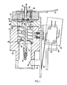
- Figure 1 is a sectional view of the head and transducer assembly of a blood cell counter according to the invention;
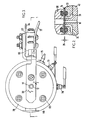
- Figure 2 is an enlargement of the area near the aperture as shown in Figure 1, taken along the section line 2-2 of Figure 3;
- Figure 3 is a top view of the counting head and transducer assembly of the blood cell counter;
- Figure 4 is a sectional view of the jeweled aperture slide which is inserted into the counting head; and
- Figure 5 is an overall view of the blood cell counter.
- The illustrated embodiment three electrodes for 1) producing a DC signal which passes through the aperture and 2) sensing the pulses produced as the poor- conducting blood cells pass through the aperture. The electrodes are of such structure and configuration so as to minimize the number of bubbles passing through the aperture, and to minimize the effect of the diluent in the path between the biasing electrodes and the aperture.
- First and second electrodes are provide on opposite sides of the aperture, and a DC bias source is connected between them. A diluted blood sample is drawn through the aperture in the direction of the first electrode, and pulses are generated by a detector circuit as blood cells pass through. This blood cell detection circuitry is connected between a third electrode, located between the aperture and the second electrode, and the first electrode. The second electrode is located externally of the channel which leads to the aperture. Any bubbles formed on this electrode are therefore outside of the detection system and cannot enter the aperture. Instead of rising through the channel and into the aperture, they reach the surface of the diluted sample within a reservoir where they enter the atmosphere.
- The length of the third electrode and magnitude of the bias current are arranged to maintain the voltage drop across the electrode length such that bubbles are not generated from the third electrode, in an amount sufficient to impair operation of the apparatus.
- The third electrode is located in close proximity to the aperture to increase the sensitivity of the apparatus and minimize the effects of any changes in the diluent resistance. Because the sample tube through whIch the diluted sample flows has a small diameter to reduce carryover, there is considerable resistance between the second electrode and the aperture. By locating the third electrode near the aperture, any adverse effects of the resistant path between the second and third electrode are eliminated.
- The path from the third electrode to the detection circuit has high DC impedance to prevent this electrode from becoming a bubble generator.
- A purge flow manifold assembly includes a fluidic circuit which is designed to maximize the cleansing effect in the area of the aperture through which the blood particles pass. In this manner, debris clogging of the aperture is cleared away and previous sample is removed from the transducer. A sample tube extends from a source of diluted blood sample or a cleansing agent to within a short distance of the aperture slide. An annulus surrounds the lower portion of the slide area and aperture, and a purge line is in fluid communication with the annulus. When a source of vacuum is applied to the purge line, a relatively high-velocity fluid stream is directed past the jeweled aperture due to the small gap provided between the slide and the sample tube and transducer housing assembly. The annulus is relatively large compared to this small purge flow gap, and promotes symmetrical bathing of the jewel. In this manner, previous sample and debris are effectively removed from the transducer.
- Figure 1 illustrates the embodiment of the invention in detail with the exceptions of the aperture slide which is inserted when the instrument is in use, and the reservoir containing the sample which is to be in fluid communication with the aspirating tube.
- A
non-metallic conduit 10 is provided through which the diluted blood sample will flow. Three electrodes, 12, 14, and 16 are located along this conduit. Thelower electrode 14, is positioned outsideconduit 10. Afilter 18 is included at the lower end of the conduit. - An
aperture slide 74 as shown in Figure 4 is designed to fit between theupper housing 20 of the transducer, and thehousing 22 which includes the assembly for purging the system of debris which may clog the aperture. "0" rings 24 and 26 insure the leakproof insertion of the slide, and provision is made so that the jeweled aperture will be positioned within theconduit 10. The aperture is described in more detail in U.S. Patent No. 3 783 376.Upper housing 20 andupper electrode 12 are interfaced by an 0-ring 28 at the point whereplate 30 is secured to this electrode.Wire 32 leads fromplate 30, and is connected to circuitry which will later be described. - The purge assembly, which is more clearly shown in Figure 2, includes
housing 22,conduit 34,annulus 33, andsolenoid valves sample tube 10,annulus 33 andvacuum purge line 34 are seen to be relatively large in comparison to apurge flow gap 35. In a successful application of this invention, thepurge flow gap 35 is 0.002 to 0.012" betweenslide 74 andhousing 40. "0"ring 38 is positioned between the purginghousing 22 andhousing 40.Electrodes housing 40, which is separated frombase 42 by agasket 44.Base 42 contains aspring 46 which is held by aretainer 48 against aprotrusion 50. A latch 53 is also secured to the base bybolts 54. The latch has aprotrusion 56 upon which the base of a sample reservoir may rest. - A number of bolts, as shown at 58, and screw 60, are used to maintain the structure of the transducer assembly, which is comprised cf the several housing and other components described above.
- A reservoir
position detecting switch 62 is also secured to the transducer assembly. Aninsulator 64 separates the switch frombracket 66. The switch includes a mountingbracket 66, an actuatinglever 68, and button 69. - Referring to Figure 3, a top view of the transducer is shown.
Terminals electrodes fitting 75 is shown for attachment of thepurge line 34. Annulus 33 (Figure 2) is in fluid communication with both thesample tube 10 and thepurge line 34. - The
aperture slide 74, as shown in Figure 4, is inserted betweenhousing assembly 22 andupper housing 20 before the counting procedure can begin. 0-rings hole 76 is formed near one end of the aperture slide and positioned to be aligned withtube 10. The forward edge is beveled to facilitate its insertion. Ajewel 78, preferably a ruby, is press fit intohole 76. The jewel has a thickness of about 0.25 mm and an outside diameter of approximately 1.20 mm. Anaperture 80 is formed in the jewel, and in this embodiment has a diameter of 70 microns. - Figure 5 illustrates the blood cell counter.
- In use, the lower end of the
conduit 10 is immersed in a diluted blood sample contained within areservoir 82. Asump 84 is in fluid communication with the conduit, and apump 86 and regulator 87 maintain the vacuum which is exerted on the system through tube 88 andsump 84. As can most clearly be seen in this figure, the countingcircuitry 90 is connected betweenelectrodes DC bias source 92 betweenelectrodes microcomputer 94 which performs calculations using the data received to generate all parameters at the end of the test. Test results are displayed by either cathoderay tube display 96 orprinter 98, although any conventional device such as a meter can also be employed. - The electrodes and their connections are shown in Figure 5. The
lower electrode 14 is located outside thesample tube 10 in such a manner that bubbles generated by electrolysis exit from the surface of the diluted sample within thereservoir 82. These bubbles will not enter the sample tube where they could then flow through theaperture 80 and impair the system. - The DC bias
source 92 is connected toelectrodes electrode 12 will rise harmlessly above the sensing zone betweenelectrodes -
Electrodes counting circuits 90, andaperture 80 is located between these electrodes. It is therefore of utmost importance that a minimum of bubbles is generated atelectrode 16, as these bubbles would flow directly intoaperture 80 thereby clogging it or causing errors within the detection system. It is also important thatelectrodes - The sensitivity of the device is also improved by keeping the distance between the sensing electrodes small. The resistance of the liquid in the sample tube is typically about 25 Kohms in this embodiment, whereas the resistance of the 7Cµ aperture is about 20 Kohms. By placing
electrodes tube 10 has a diameter of approximately 0.05". - Bubble generation caused by electrolysis of
electrode 16 is minimized or eliminated by two features. First, the detection circuitry is connected such that significant current is not drawn from the electrode. A high impedance return path to the circuitry is therefore provided. Secondly, the length of theelectrode 16 in the diluent path and the magnitude of the DC bias current are arranged to minimize the voltage drop across the electrode length. - The resistance R of a uniform conductor is defined by the expression Rp=

electrode 16 is 0.095 inches, the diameter of the sample tube is 0.07 inches, and the resistivity of the dilution is about 20 ohm-inches. Applying the above formula, the resistance is found to be 494 ohms. The voltage drop V is defined by the formula V = I R, and for a 1 ma DC current, the voltage drop is 0.494 volts. It should be understood that other tube diameters, electrode lengths, and biasing currents may be utilized in providing a voltage drop of less than about 1.2 volts. 1.2 volts has been found to be a good target figure, although this particular voltage is not to be regarded as critical. - To begin the testing procedure,
reservoir 82 is positioned againstretainer 48 so as to compressspring 46. The spring is compressed until the reservoir bottom rests against theprotrusion 56 provided onlatch 52.Switch 62 provides information to the computer as to whether the reservoir is inserted.Actuation level 68 presses button 69 to actuate the switch once the reservoir is in place. - The
reservoir 82 is positioned such that the sample may be aspirated throughfilter 18,conduit 10,aperture 80,conduit 10, and intosump 84. The pump operates to provide the negative pressure necessary for the aspiration. - As the sample is aspirated through the conduits and electrodes, the blood cells are counted in a conventional manner based upon the change in current between the detection electrodes each time a blood cell enters the aperture. Pulses are produced and counting
circuitry 90 counts the number of blood cells. This information is relayed tocomputer 94 which causesprinter 98 to record the results and/or cathoderay tube display 96 to visually display the information. The counting process is described in greater detail in U.S. Patent 3 812 425 and 3 973 194, as are the basic circuit components. - Before the next sample is aspirated through the electrodes to commence the counting procedure, the sample presently within the transducer between the
filter 18 andaperture slide 74 is removed. This is accomplished by actuation ofpump 86. which provides a source of vacuum pressure, and the opening of asolenoid valve 36 on the purge line such that fluid flows through this line into thesump 84. - The purge system basically includes a
pump 86 for supplying negative pressure, thesump 84 which temporarily stores liquid drawn into it, the conduit connecting the sump with the transducer assembly, and the novel fluidic circuit within the transducer. This circuit includes the relativelylarge sample tube 10, thesmall gap 35 between theaperture slide 74 and thehousing 40, the relativelylarge annulus 33 which surrounds the lower portion of the slide, and the relatively largediameter purge line 34. - The
pump 86 supplies the negative pressure for the system, and purging is accomplished upon the closing ofvalve 37 and opening ofvalve 36. A total pressure drop A PT must occur between the bottom ofsample tube 10 and the pump. It is one of the primary objectives of the invention to obtain the greatest proportion of this drop across thegap 35 between the slide and housing. The pressure drop across the gap will be referred to as Δ PG, so it is the ratio of ΔPG/ΔPT that will be maintained as high as possible. This is accomplished by providing system components which minimize pressure drop throughout the remainder of the system. By maintaining a ΔPG as high as possible, the velocity of the liquid is significantly increased in the gap area. Because a high velocity stream is directed across the slide in the area near the aperture, debris within or near the aperture is most effectively cleared away. - To obtain the aforementioned advantages of a relatively high velocity stream near the aperture, the sample tube, annulus, and purge line are all of such dimensions that fluid velocity will be relatively slow within them, and the pressure drop is minimized. All have large dimensions than the gap as clearly shown in Figures 2 and 5. Losses due to frictional forces and turbulence are accordingly reduced. The gap is shown to be of relatively small dimensions, and a correspondingly high drop in pressure is produced. Due to this drop, the liquid velocity increases in this area thus enhancing its cleansing action near the aperture.
- Another advantageous feature of the purge system is the provision of the
annular region 33 which surrounds the gap. As shown in Figure 1, the annulus appears to be symmetrical. The view shown in Figure 2 indicates there is actually a lobed portion near its junction withpurge line 34. In practice, the annulus may be either symmetrical or lobed, and there are advantages in both designs. - The annulus is provided for the basic purpose of insuring a uniform flow about the jewel. If no such area surrounded the gap, liquid would tend to flow directly to whichever side the purge line was attached. Consequently, dirt or debris on the opposite side of the jewel might not be effectively removed. By providing an annulus or other open area of relatively large dimensions surrounding the gap, a fountain-like flow from the top of the
tube 10 occurs across the face of the jewel. - If the annulus is symmetrical, the flow is uniform in nearly all radial directions. The pressure drop within the annulus itself is also minimized with such a configuration.
- Rather than being completely symmetrical, the annulus which is most clearly shown in Figure 2 indicates that it contains a lobed portion. This reduces the volume of the annular region as compared with a symmetrical annulus extending to the outer periphery of the lobe. Although the uniformity of flew from the sample tube is somewhat impaired, there is still sufficient high velocity flow in all radial directions to insure effective cleaning of the jewel. The reduced volume of this configuration is advantageous in that it minimizes the area in which air may be trapped. As previously explained, air bubbles within the aperture are undesirable. A further advantage of the smaller annulus occurs when a hemoglobin head (not shown) is located along the purge line. There is reduced carryover of previous sample, and less new sample is thereby required to flush the system before performing a new test.
Claims (10)
Applications Claiming Priority (2)
| Application Number | Priority Date | Filing Date | Title |
|---|---|---|---|
| US852953 | 1977-11-18 | ||
| US05/852,953 US4180091A (en) | 1977-11-18 | 1977-11-18 | Purging means for aperture of blood cell counter |
Publications (2)
| Publication Number | Publication Date |
|---|---|
| EP0002103A1 true EP0002103A1 (en) | 1979-05-30 |
| EP0002103B1 EP0002103B1 (en) | 1981-03-18 |
Family
ID=25314635
Family Applications (1)
| Application Number | Title | Priority Date | Filing Date |
|---|---|---|---|
| EP19780300472 Expired EP0002103B1 (en) | 1977-11-18 | 1978-10-09 | A blood cell counter having a purging system |
Country Status (5)
| Country | Link |
|---|---|
| US (1) | US4180091A (en) |
| EP (1) | EP0002103B1 (en) |
| JP (1) | JPS5499495A (en) |
| DE (1) | DE2860550D1 (en) |
| IT (1) | IT1102317B (en) |
Cited By (4)
| Publication number | Priority date | Publication date | Assignee | Title |
|---|---|---|---|---|
| EP0110410A2 (en) * | 1982-12-03 | 1984-06-13 | The Boeing Company | Debris detection system and method |
| EP0129008A1 (en) * | 1983-05-31 | 1984-12-27 | Contraves Ag | Draining system |
| EP0228453A1 (en) * | 1985-06-24 | 1987-07-15 | Nova Celltrax, Inc. | Control means for a blood analysis system |
| EP0275409A2 (en) * | 1986-05-28 | 1988-07-27 | Sumitomo Electric Industries Limited | Particle analyzer and a system utilizing the same |
Families Citing this family (5)
| Publication number | Priority date | Publication date | Assignee | Title |
|---|---|---|---|---|
| GB2062472B (en) * | 1979-10-12 | 1984-02-08 | Kimura Bed Mfg | Vacuum suction type urinating aid |
| JPS61160038A (en) * | 1985-01-08 | 1986-07-19 | Sumitomo Electric Ind Ltd | Particle detector |
| US4977517A (en) * | 1988-09-21 | 1990-12-11 | Toni Diagnostics, Inc. | Leak and clog detection and removal system for use with particle counters |
| US4962778A (en) * | 1989-03-07 | 1990-10-16 | Driskill Brent J | Backwashing dispenser for air conditioner drain pans |
| US4972137A (en) * | 1989-05-31 | 1990-11-20 | Coulter Electronics, Inc. | Isolation circuit for blood cell counter |
Citations (4)
| Publication number | Priority date | Publication date | Assignee | Title |
|---|---|---|---|---|
| DE1291544B (en) * | 1964-05-01 | 1969-03-27 | Coulter Electronics | Device for determining deposits in or around a measuring opening of a device for counting and classifying particles of small diameter suspended in an electrolytic liquid |
| US3783376A (en) * | 1972-06-21 | 1974-01-01 | Becton Dickinson Co | Particle counter having removable aperture slide |
| US3979669A (en) * | 1973-09-26 | 1976-09-07 | Coulter Electronics, Inc. | Particle analyzing system |
| FR2309856A1 (en) * | 1975-04-30 | 1976-11-26 | Coulter Electronics | OPENING MODULE FOR A PARTICLE ANALYSIS APPARATUS |
Family Cites Families (1)
| Publication number | Priority date | Publication date | Assignee | Title |
|---|---|---|---|---|
| US3746976A (en) * | 1971-04-07 | 1973-07-17 | Coulter Electronics | Self-cleaning aperture tube for coulter study apparatus |
-
1977
- 1977-11-18 US US05/852,953 patent/US4180091A/en not_active Expired - Lifetime
-
1978
- 1978-10-09 DE DE7878300472T patent/DE2860550D1/en not_active Expired
- 1978-10-09 EP EP19780300472 patent/EP0002103B1/en not_active Expired
- 1978-10-17 JP JP12777678A patent/JPS5499495A/en active Pending
- 1978-11-17 IT IT2988578A patent/IT1102317B/en active
Patent Citations (4)
| Publication number | Priority date | Publication date | Assignee | Title |
|---|---|---|---|---|
| DE1291544B (en) * | 1964-05-01 | 1969-03-27 | Coulter Electronics | Device for determining deposits in or around a measuring opening of a device for counting and classifying particles of small diameter suspended in an electrolytic liquid |
| US3783376A (en) * | 1972-06-21 | 1974-01-01 | Becton Dickinson Co | Particle counter having removable aperture slide |
| US3979669A (en) * | 1973-09-26 | 1976-09-07 | Coulter Electronics, Inc. | Particle analyzing system |
| FR2309856A1 (en) * | 1975-04-30 | 1976-11-26 | Coulter Electronics | OPENING MODULE FOR A PARTICLE ANALYSIS APPARATUS |
Cited By (8)
| Publication number | Priority date | Publication date | Assignee | Title |
|---|---|---|---|---|
| EP0110410A2 (en) * | 1982-12-03 | 1984-06-13 | The Boeing Company | Debris detection system and method |
| EP0110410A3 (en) * | 1982-12-03 | 1985-01-23 | The Boeing Company | Debris detection system and method |
| EP0129008A1 (en) * | 1983-05-31 | 1984-12-27 | Contraves Ag | Draining system |
| US4567908A (en) * | 1983-05-31 | 1986-02-04 | Contraves Ag | Discharge system and method of operating same |
| EP0228453A1 (en) * | 1985-06-24 | 1987-07-15 | Nova Celltrax, Inc. | Control means for a blood analysis system |
| EP0228453A4 (en) * | 1985-06-24 | 1991-10-23 | Nova Celltrax, Inc. | Control means for a blood analysis system |
| EP0275409A2 (en) * | 1986-05-28 | 1988-07-27 | Sumitomo Electric Industries Limited | Particle analyzer and a system utilizing the same |
| EP0275409A3 (en) * | 1986-05-28 | 1990-01-31 | Sumitomo Electric Industries Limited | Particle analyzer and a system utilizing the same |
Also Published As
| Publication number | Publication date |
|---|---|
| US4180091A (en) | 1979-12-25 |
| EP0002103B1 (en) | 1981-03-18 |
| IT7829885A0 (en) | 1978-11-17 |
| IT1102317B (en) | 1985-10-07 |
| DE2860550D1 (en) | 1981-04-16 |
| JPS5499495A (en) | 1979-08-06 |
Similar Documents
| Publication | Publication Date | Title |
|---|---|---|
| US4165484A (en) | Particle counting apparatus utilizing various fluid resistors to maintain proper pressure differentials | |
| US4395676A (en) | Focused aperture module | |
| EP0002103B1 (en) | A blood cell counter having a purging system | |
| US5376878A (en) | Multiple-aperture particle counting sizing and deformability-measuring apparatus | |
| US8030059B2 (en) | Apparatus for measuring extracellular potential | |
| EP1690157B1 (en) | Method and apparatus to reject electrical interference in a capacitive liquid level sensor system | |
| EP0488509A2 (en) | Particle detector, particle detecting apparatus and method of operating a particle detector | |
| EP1206692B1 (en) | Particle characterisation apparatus | |
| JP2010019862A (en) | Method of detecting fluid flow | |
| EP1929273B1 (en) | Detection and subsequent removal of an aperture blockage | |
| EP0870186B1 (en) | Electrode assembly | |
| US4157499A (en) | Blood cell counter having dual testing heads | |
| US3783376A (en) | Particle counter having removable aperture slide | |
| US3395344A (en) | Particle studying apparatus with selfclearing scanner element | |
| US3958177A (en) | Particle analyzing device with changeable aperture means | |
| JPH0121467B2 (en) | ||
| US4375615A (en) | Apparatus for counting particles in a liquid suspension | |
| US4140966A (en) | Particle analyzing apparatus and fluid circulating system therefor | |
| US3781675A (en) | Self priming conductivity cell | |
| JP4440840B2 (en) | Particle number measuring device | |
| GB1590899A (en) | Blood particle counter having threeelectrode counting head | |
| JP4567540B2 (en) | Cell count device and cell count cartridge | |
| JP3909050B2 (en) | Blood cell counter | |
| WO1989004961A1 (en) | Hematology cell counting apparatus | |
| US4863868A (en) | Apparatus for detecting the presence of micro organism in liquid |
Legal Events
| Date | Code | Title | Description |
|---|---|---|---|
| PUAI | Public reference made under article 153(3) epc to a published international application that has entered the european phase |
Free format text: ORIGINAL CODE: 0009012 |
|
| AK | Designated contracting states |
Designated state(s): DE FR GB |
|
| 17P | Request for examination filed | ||
| DET | De: translation of patent claims | ||
| GRAA | (expected) grant |
Free format text: ORIGINAL CODE: 0009210 |
|
| AK | Designated contracting states |
Designated state(s): DE FR GB |
|
| REF | Corresponds to: |
Ref document number: 2860550 Country of ref document: DE Date of ref document: 19810416 |
|
| PGFP | Annual fee paid to national office [announced via postgrant information from national office to epo] |
Ref country code: FR Payment date: 19841009 Year of fee payment: 7 |
|
| PGFP | Annual fee paid to national office [announced via postgrant information from national office to epo] |
Ref country code: DE Payment date: 19841106 Year of fee payment: 7 |
|
| PG25 | Lapsed in a contracting state [announced via postgrant information from national office to epo] |
Ref country code: FR Free format text: LAPSE BECAUSE OF NON-PAYMENT OF DUE FEES Effective date: 19870630 |
|
| GBPC | Gb: european patent ceased through non-payment of renewal fee | ||
| REG | Reference to a national code |
Ref country code: FR Ref legal event code: ST |
|
| PG25 | Lapsed in a contracting state [announced via postgrant information from national office to epo] |
Ref country code: DE Effective date: 19871201 |
|
| PG25 | Lapsed in a contracting state [announced via postgrant information from national office to epo] |
Ref country code: GB Effective date: 19881117 |
|
| PLBE | No opposition filed within time limit |
Free format text: ORIGINAL CODE: 0009261 |
|
| STAA | Information on the status of an ep patent application or granted ep patent |
Free format text: STATUS: NO OPPOSITION FILED WITHIN TIME LIMIT |