EP0003567A1 - Interference suppression of QRS detector by automatic threshold leveling - Google Patents
Interference suppression of QRS detector by automatic threshold leveling Download PDFInfo
- Publication number
- EP0003567A1 EP0003567A1 EP79100299A EP79100299A EP0003567A1 EP 0003567 A1 EP0003567 A1 EP 0003567A1 EP 79100299 A EP79100299 A EP 79100299A EP 79100299 A EP79100299 A EP 79100299A EP 0003567 A1 EP0003567 A1 EP 0003567A1
- Authority
- EP
- European Patent Office
- Prior art keywords
- signal
- detector
- input
- qrs
- threshold value
- Prior art date
- Legal status (The legal status is an assumption and is not a legal conclusion. Google has not performed a legal analysis and makes no representation as to the accuracy of the status listed.)
- Granted
Links
Images


Classifications
-
- A—HUMAN NECESSITIES
- A61—MEDICAL OR VETERINARY SCIENCE; HYGIENE
- A61B—DIAGNOSIS; SURGERY; IDENTIFICATION
- A61B5/00—Measuring for diagnostic purposes; Identification of persons
- A61B5/24—Detecting, measuring or recording bioelectric or biomagnetic signals of the body or parts thereof
- A61B5/30—Input circuits therefor
- A61B5/307—Input circuits therefor specially adapted for particular uses
- A61B5/308—Input circuits therefor specially adapted for particular uses for electrocardiography [ECG]
-
- A—HUMAN NECESSITIES
- A61—MEDICAL OR VETERINARY SCIENCE; HYGIENE
- A61B—DIAGNOSIS; SURGERY; IDENTIFICATION
- A61B5/00—Measuring for diagnostic purposes; Identification of persons
- A61B5/24—Detecting, measuring or recording bioelectric or biomagnetic signals of the body or parts thereof
- A61B5/30—Input circuits therefor
-
- A—HUMAN NECESSITIES
- A61—MEDICAL OR VETERINARY SCIENCE; HYGIENE
- A61B—DIAGNOSIS; SURGERY; IDENTIFICATION
- A61B5/00—Measuring for diagnostic purposes; Identification of persons
- A61B5/24—Detecting, measuring or recording bioelectric or biomagnetic signals of the body or parts thereof
- A61B5/316—Modalities, i.e. specific diagnostic methods
- A61B5/318—Heart-related electrical modalities, e.g. electrocardiography [ECG]
- A61B5/346—Analysis of electrocardiograms
- A61B5/349—Detecting specific parameters of the electrocardiograph cycle
- A61B5/352—Detecting R peaks, e.g. for synchronising diagnostic apparatus; Estimating R-R interval
Definitions
- the invention relates to a QRS detector with automatic threshold value determination, which can be used for devices for monitoring the cardiac activity of living beings, in which the threshold value of the detector starting point can be automatically shifted as a function of the input signal, for example a rectified QRS signal.
- QRS filter 6 QRS signal 28 is generated from 27, which is used in the automatic threshold value 26 a threshold value 29 is formed.
- a pulse signal 24 is generated in the QRS detector 8 by linking between 28 and 29, the further processing of which is known from FIGS. 1 and 2.
- heart rate monitors have been known which have a response threshold that is independent of the polarity of the QRS complex and are also suitable for monitoring the heart activity of patients with implanted or external pacemakers.
- pacemaker suppression 30 devices for amplitude selection, designated in FIG. 5 as pacemaker suppression 30, which are in the transmission path upstream of the actual QRS filter 6 must be arranged, and a two-way rectifier 32, arranged at the output of the QRS filter 6, which eliminates any sign dependency of the QRS detection by forming the amount of the signal voltage.
- FIG. 6 serves to illustrate the function of the pacemaker mask 30 and the two-way rectifier 32.
- the pulse-free ECG 36 arises from the EKG 34, and a QRS from the QRS filter 6 Signal 37 and a rectified QRS signal 38 is formed by subsequent amount formation in the two-way rectifier 32.
- the threshold automatic 26 generates a threshold value 39 from the signal 38, from which a pulse signal 40 is derived by linking to 38 through the QRS detector 8.
- the properties of the automatic threshold value 26 are of great importance for the functional reliability of such a heart rate monitor, particularly when it is a question of monitoring an ECG signal with a changing shape of QRS complexes or with superimposed interference voltages. This explains the need for embodiments of such devices with automatic threshold value and higher interference voltage security.
- FIG. 7 shows an early form of a QRS detector with an automatic threshold, in which both the rectifier property necessary for the function and the discrimination by the input characteristic of a transistor 43 are achieved.
- a capacitor 45 serves to couple the input signal 44 (for example the QRS signal 28 according to FIG. 4) and as a storage element for the threshold value 29 in FIG. 4. The current flow through this capacitor 45 disappears during pauses in the signal 44.
- a transistor 47 conducts due to the current supplied through a resistor 46 to its base. The resulting base-emitter voltage of transistor 47 is divided by resistors 48 and 49 and thus determines the voltage between the base and emitter of transistor 43 as voltage drop across resistor 49.
- transistors 43 and 47 are of the same type, have approximately the same base emitter threshold voltage, and resistors 46 and 50 are of similar size, transistor 43 is blocked and the voltage drop on Resistor 48 determines the minimum threshold. Positive deflections of the input signal 44, which exceed the minimum threshold mentioned, make the transistor 43 conductive. The collector current of this transistor 43 flows through the resistor 46 and thereby blocks the transistor 47. The load resistor 50 at the circuit output thus produces a positive output signal 51.
- capacitor 45 is recharged by its input current. This reloading creates a threshold value 29 in the amount of the amplitude of the QRS signal 28 supplied to the circuit input, which, as shown above, decreases to the minimum threshold value until the threshold value 29 is built up again by further QRS signals 28.
- the threshold value is broken down in the circuit according to FIG. 7 according to an exponential function, the time constant of which is determined by the capacitor 45 and the parallel connection of the resistors 48 and 49, since in the discharge phase the resistor 48 is connected across the base-emitter path of the transistor which is now switched on 47 is at reference potential (OV).
- 8 shows the voltage curve 57 at the node 53 for an assumed QRS signal 56 at the input terminal 52, the course of the actual threshold value 58, as it is stored in capacitor 45 with the minimum threshold value 58a, and the course 59 of the pulse signal at the output 55 of the QRS detector, which via the connection 11 for further processing, for example in the pulse shaper 12 etc. as shown in FIG Fig. 1 is present.
- an automatic QRS detector according to FIG. 9 was installed on a two-way rectifier 32 arranged behind a QRS filter 6 connected (see Fig. 5).
- the amplifier 56 delivers a positive output signal 58 at its output 57 when the signal 59 at its input 60 becomes greater than the threshold value 63 at the input 61 and stored in the capacitor 62.
- this threshold value 63 is increased when the input voltage 59 has the voltage at point 61 exceeds the forward voltage of diode 64.
- a minimum threshold value 63a is restored during the modulation pauses by discharging the capacitor 62 via the resistor 65 to an end value which is determined by the operating voltage + U B and the voltage divider from the resistors 65 and 66.
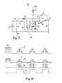
- FIG. 10 shows the signal voltages that occur when the QRS detector shown in FIG. 9 is operated with automatic threshold values.
- 59 represents the input signal, 63 the threshold value formed therefrom, 58 the pulse signal at the output of the QRS detector and 67 the standardized QRS pulse signal, which is generated from 58 in a pulse shaper 12 according to FIG. 5.
- the automatic QRS detector shown in FIG. 9 also does not have the ability to distinguish QRS complexes in signal 59 from interfering alternating currents 59a, as is shown by the temporal course of signals 58 and 67 in FIG. 10.
- the threshold value is obtained from the averaged peak value of the EKG signal, it is no longer possible to reliably determine the signal in the case of fluctuating ECG and thus QRS amplitudes, since, for example, the threshold value is too high in the case of a suddenly occurring weak QRS signal.
- the invention is therefore based on the object of providing a simply constructed QRS detector which is insensitive to periodic interference voltages and which automatically adjusts the threshold value of the detector, and which is still reliably triggered by the QRS pulses even in the case of fluctuating ECG signals.
- the invention was developed in connection with tests on heart rate monitors; for such devices the fail-safe QRS detector acc. the invention represents a significant improvement.
- a QRS detector is also suitable for other devices in the field of mid-medical technology for monitoring the heart activity of living beings. Examples of use are controlled defibrillators, demand pacemakers, devices for synchronized injection, devices for synchronous assisted circulation and other possible uses in which a periodically occurring characteristic signal of varying strength is to be recorded, which can be easily superimposed by periodic interference voltages.
- the QRS-detector whose active assembly preferably consists of a comparator or amplifier block, an adjusting circuit whose input side is connected upstream on the - derived from the input signal of - the one, for example the (-) g Eingan an operational amplifier, the arithmetic mean of the input signal Threshold value is pressed while the other input, for example the + input of the operational amplifier, is acted upon by a signal proportional to the input signal.
- the proportional reduction of the input signal to generate the second signal which acts on the (+) input is expediently carried out by a simple ohmic voltage divider which reduces the input signal by a factor which corresponds to the ratio of the peak value to the arithmetic mean value of the input voltage.
- a simple RC low-pass filter can be used, which is dimensioned in such a way that integration takes place over approximately one period of the QRS signal.
- the threshold value input of the detector can be connected to a fixed potential via an ohmic resistor, as was explained above in connection with FIG. 9. Alternatively, you can the other detector input, which is acted upon by the second signal, can also be clamped to a lower minimum potential.
- the arithmetic mean value of the input signal is used as the threshold value 63.
- the comparator 56 used in this case as the QRS detector is the first signal mentioned threshold value 63 and as a second signal a signal 74 is supplied which is proportional to the input signal 59 and has crest amplitudes which, in the case of an interference signal 59a, are smaller than the mentioned associated threshold value 63.
- This can be achieved in a simple manner by suitable dimensioning of voltage divider resistors 72 and 73. This measure does not affect the functionality of the QRS detector, as will be shown.
- this voltage divider 72, 73 For the dimensioning of this voltage divider 72, 73, according to the invention, use is made of a relationship between peak value ü and arithmetic mean u known from the theory of rectifiers for a signal generated by a two-way rectification from an AC sine voltage:
- the rectified QRS signal 59 supplied by the source represented by symbol 70 is fed to the input represented by terminals 68 and 69.
- the connection between terminal 68 and input terminal 61 of the element 56 used as a QRS detector, which in this case can be a comparator or an amplifier, is made by the resistor 65.
- a capacitor 62 is located between the terminal 61 and the terminal 69, which is connected to the resistor 65 together forms an RC low-pass filter for generating the arithmetic mean 63 of the input voltage 59.
- the connection between terminal 68 and input terminal 60 of the comparator 56 is made via a resistor 72, and a further resistor 73 is arranged between terminals 60 and 69.
- These resistors 72 and 73 form a voltage divider with which the amplitude ratio between the input voltage 59 and the voltage 74 between the terminals 60 and 69 is set according to the invention to a value k 1,5 1.57:
- Such an automatic QRS detector according to the invention therefore only delivers pulses at the output 57 of the comparator 56 if the peak value of the input signal 59 is greater than the arithmetic mean value of the input signal 59 multiplied by factor k. This condition is fulfilled when processing real ECG signals, but not with periodic interference voltages, ie the circuit has an interference suppression effect.
- the described QRS detector according to the invention can be combined with a circuit for specifying a minimum threshold and an automatic amplitude control.
- the minimum value of the voltage across the capacitor 62 is either increased with a resistor 66, known from FIG. 9, between the terminal 61 and the operating voltage + U B , or an additional resistor 75 is used between an operating voltage -U B and the terminal 60 lowers the voltage at this terminal 60.
- the amplitude-dependent threshold value is built up by storing the peak value of the span
- the function group 56 can be designed as a differential amplifier with a plus input 60, a minus input 61 and an output 57, supplemented by a diode 76, the anode of which with the amplifier output 57 and the cathode of which is connected to the amplifier input 61.
- the capacitor 62 can expediently be connected by a series circuit comprising a capacitor 77 and a resistor 78 replace. This is achieved by storing a threshold value in the capacitor 77 via the diode 76, which remains below the peak value of the voltage 74. As a result, no change occurs in the AC interference according to the invention by forming a threshold value from the signal mean.
- FIG. 13 represent the mode of operation of an interference-free QRS detector according to the invention with automatic threshold value determination, which is composed in the manner shown in FIG. 11 from elements 56, 65, 72, 73, 76, 77, 78 and 66 or 75 is.
- the circuit acc. 11 can easily be modified for an input signal 59 with reversed polarity, ie with deflections negative towards terminal 69.
- the diode 76 must be used in reverse and that for the The minimum threshold responsible resistor 66 or 75 must be connected to the opposite operating voltage -U B or + U B. In this case, all of the signals shown in FIG. 13, ie 59, 74, 63 and 58, occur with reversed polarity.
Landscapes
- Health & Medical Sciences (AREA)
- Life Sciences & Earth Sciences (AREA)
- Cardiology (AREA)
- Heart & Thoracic Surgery (AREA)
- Molecular Biology (AREA)
- Pathology (AREA)
- Engineering & Computer Science (AREA)
- Biomedical Technology (AREA)
- Physics & Mathematics (AREA)
- Medical Informatics (AREA)
- Biophysics (AREA)
- Surgery (AREA)
- Animal Behavior & Ethology (AREA)
- General Health & Medical Sciences (AREA)
- Public Health (AREA)
- Veterinary Medicine (AREA)
- Electrotherapy Devices (AREA)
- Measurement And Recording Of Electrical Phenomena And Electrical Characteristics Of The Living Body (AREA)
Abstract
Description
Gegenstand der Erfindung ist ein QRS-Detektor mit automatischer Schwellenwertbestimmung verwendbar für Geräte zur Überwachung der Herztätigkeit von Lebewesen, bei dem der Schwellenwert des Detektor-Einsatzpunkts in Abhängigkeit vom Eingangssignal, beispielsweise einem gleichgerichteten QRS-Signal automatisch verschiebbar ist.The invention relates to a QRS detector with automatic threshold value determination, which can be used for devices for monitoring the cardiac activity of living beings, in which the threshold value of the detector starting point can be automatically shifted as a function of the input signal, for example a rectified QRS signal.
Geräte der hier inrede stehenden Gattung zur Erfassung der Herztätigkeit sind etwa seit dem Jahre 1960 auf dem Markt. Zur Verdeutlichung der der Erfindung zugrundeliegenden Aufgabe sollen die Stufen der Weiterentwicklung dieser Geräte hier in großen Zügen dargestellt werden.Devices of the type in question here for recording cardiac activity have been on the market since about 1960. To clarify the object on which the invention is based, the stages in the further development of these devices are to be outlined in broad outline here.
Die ersten Herzfrequenzmonitoren (abgekürzt HFMen), wie diese Uberwachungsgeräte meist genannt werden, besassen etwa die in Fig. 1 dargestellten Funktionsgruppen, in denen die in Fig. 2 angedeuteten Signale verarbeitet werden:
- Die am Körper eines Patienten 1 durch im allgemeinen an der Oberfläche
angebrachte Elektroden 2 abgenommene, meist EKGgenannte Herzaktionsspannung 20 gelangt überElektrodenleitungen 3, einen Verstärker 4 und eineVerbindung 5 zu einem QRS-Filter 6. Dort wird aus dem EKG 20 das QRS-Signal 21 isoliert, das als für die Herzaktion charakteristisches Signal über eineVerbindung 7 zu einem QRS-Detektor 8 gelangt und dort mit dem über eineVerbindung 9zugeführten Schwellenwert 22 verknüpft wird. Aus dem dabeientstehenden Impulssignal 23 am Ausgang des QRS-Detektors 8 wird in dem über eineVerbindung 11angeschlossenen Impulsformer 12 ein standardisierter QRS-Impuls 24 erzeugt. Dieser erlaubt einen ordnungsgemäßen Betrieb eines über eineVerbindung 13angekoppelten Frequenzmessers 14 undweiteruber Verbindungen nachgeschalteterfunktionsgruppen Anzeige 16 undAlarmeinrichtung 19, durch die bei physiologisch bedenklichem Herzrhythmus ein Warnsignal erzeugt werden soll.
- The
cardiac action voltage 20, usually referred to as EKG, which is removed from the body of a patient 1 byelectrodes 2 generally attached to the surface, passes viaelectrode lines 3, an amplifier 4 and aconnection 5 to aQRS filter 6. Isolatessignal 21, which, as a signal characteristic of the cardiac action, reaches aQRS detector 8 via aconnection 7 and is linked there with thethreshold value 22 supplied via aconnection 9. The resultingpulse signal 23 at the output of theQRS detector 8 becomes astandardized QRS pulse 24 in thepulse shaper 12 connected via aconnection 11 generated. This permits proper operation of afrequency meter 14 coupled via aconnection 13 and further viaconnections alarm device 19, by means of which a warning signal is to be generated in the event of a physiologically questionable heart rhythm.
Die Funktionstüchtigkeit solcher Herzfrequenzmonitoren war eingeschränkt durch die geringe Selektivität der damals üblichen QRS-Filter 6. Außerdem war von Nachteil, daß der Schwellenwert 22 des QRS-Detektors 8 von Hand eingestellt werden mußte und bei dieser Einstellung Amplitude und Vorzeichen des EKGs des betreffenden Patienten berücksichtigt werden mußten.The functionality of such heart rate monitors was limited by the low selectivity of the
Die Problematik des Einsatzes von Monitoren dieser Art bei einem EKG 20 mit wechselnden Amplituden und Formen der QRS-Komplexe ist offensichtlich.The problem of using monitors of this type on an
Die nächste Generation von Herzfrequenzmonitoren (Fig. 3) kam etwa zwischen 1965 und 1970 auf den Markt und war zur besseren Erfassung der QRS-Komplexe im EKG 20 mit einer über Verbindung 25 am QRS-Filter 6 angeschlossenen Schwellenwertautomatik 26 und einem verbesserten QRS-Filter 6 ausgestattet.Damit fiel die unsichere Handeinstellung des Schwellenwerts 22 weg. Übrig blieb allerdings eine Abhängigkeit der zur Herzfrequenzüberwachung erforderlichen Mindest-QRS-Amplitude vom Vorzeichen des EKG-Signals 20, weil beim beschriebenen HFM-Konzept die "Plus-Minus-Automatik" nur auf der Ausnutzung von Uberschwingern am Ausgang des QRS-Filters 6 beruht.The next generation of heart rate monitors (FIG. 3) came onto the market around 1965 and 1970 and was for better detection of the QRS complexes in the
Das Zusammenwirken der in Fig. 3 dargestellten Baugruppen eines HFM veranschaulicht Fig. 4 am Beispiel der Verarbeitung eines mit wechselnder QRS-Polarität auftretenden EKGs 27. Im QRS-Filter 6 entsteht aus 27 das QRS-Signal 28, aus dem in der Schwellenwert-Automatik 26 ein Schwellenwert 29 gebildet wird. Im QRS-Detektor 8 wird schließlich durch Verknüpfung zwischen 28 und 29 ein Impuls-Signal 24 erzeugt, dessen weitere Verarbeitung aus Fig. 1 und Fig. 2 bekannt ist.The interaction of the modules of an HFM shown in FIG. 3 is illustrated in FIG. 4 using the example of the processing of an
Schließlich sind seit etwa 1970 Herzfrequenzmonitoren bekannt, die eine von der Polarität des QRS-Komplexes unabhängige Ansprechschwelle besitzen und außerdem zur Überwachung der Herztätigkeit von Patienten mit implantierten oder externen Schrittmachern geeignet sind. Wie in Fig. 5 dargestellt, benötigen solche Monitoren zusätzlich zu dem zur QRS-Selektion erforderlichen (linearen Frequenz-) Filter 6 Einrichtungen zur Amplitudenselektion, in Fig. 5 als Schrittmacher-Ausblendung 30 bezeichnet, die im Übertragungsweg vor dem eigentlichen QRS-Filter 6 angeordnet sein müssen, und einen Zweiweg-Gleichrichter 32 , angeordnet am Ausgang des QRS-Filters 6, der jegliche Vorzeichenabhängigkeit der QRS-Erkennung durch Bildung des Betrages der Signalspannung beseitigt.Finally, since around 1970, heart rate monitors have been known which have a response threshold that is independent of the polarity of the QRS complex and are also suitable for monitoring the heart activity of patients with implanted or external pacemakers. As shown in FIG. 5, in addition to the (linear frequency)
Zur Illustration der Funktion der Schrittmacher-Ausblendung 30 und des Zweiweg-Gleichrichters 32 dient die Darstellung Fig. 6. Durch Entfernung von Impulsen, z.B. Schrittmacherimpulsen 35 entsteht aus dem EKG 34 das impulsbefreite EKG 36, aus dem durch das QRS-Filter 6 ein QRS-Signal 37 und durch nachfolgende Betragsbildung im Zweiweg-Gleichrichter 32 ein gleichgerichtetes QRS-Signal 38 gebildet wird. Die Schwellenwert-Automatik 26 erzeugt aus dem Signal 38 einen Schwellenwert 39, aus dem durch Verknüpfung mit 38 durch den QRS-Detektor 8 ein Impulssignal 40 hergeleitet wird.The illustration in FIG. 6 serves to illustrate the function of the pacemaker mask 30 and the two-
Aus Fig. 6 geht weiter hervor, daß zu jeder R-Zacke im EKG 34 nur ein standardisierter QRS-Impuls 41 im Impulsformer 12 erzeugt wird, auch dann, wenn zu einer R-Zacke im QRS-Detektor 8 eine an sich mehrdeutige Impuls-.- gruppe 42 auftritt. Das wird durch die Eigenzeit des Impulsformers 12 erreicht.6 further shows that only a standardized QRS pulse 41 is generated in the
Von großer Bedeutung für die Funktionssicherheit eines solchen Herzfrequenzmonitors sind die Eigenschaften der Schwellenwertautomatik 26, besonders wenn es sich um die Überwachung eines EKG-Signals mit wechselnder Gestalt von QRS-Komplexen handelt oder mit überlagerten Störspannungen. Daraus erklärt sich der Bedarf für Ausführungsformen solcher Geräte mit Schwellenwertautomatik und höher Störspannungssicherheit.The properties of the
Fig. 7 stellt eine frühe Form eines QRS-Detektors mit automatischer Schwelle dar, in der sowohl die für die Funktion notwendige Gleichrichtereigenschaft als auch die Diskrimination durch die Eingangskennlinie eines Transistors 43 erreicht wird. Zur Ankopplung des Eingangssignals 44 (z.B. des QRS-Signals 28 nach Fig. 4) und als Speicherelement für den Schwellenwert 29 in Fig. 4 dient ein Kondensator 45. Der Stromfluß durch diesen Kondensator 45 verschwindet in Pausen des Signals 44. Ein Transistor 47 leitet infolge des über einen Widerstand 46 seiner Basis zugeführten Stromes. Die dadurch auftretende Basis-Emitter-Spannung von Transistor 47 wird durch Widerstände 48 und 49 aufgeteilt und bestimmt so die Spannung zwischen Basis und Emitter von Transistor 43 als Spannungsabfall am Widerstand 49. Unter der Voraussetzung, daß die Transistoren 43 und 47 vom gleichen Typ sind, älsoetwa gleiche Basis-Emitterschwellenspannung aufweisen und die Widerstände 46 und 50 ähnliche Größe haben, ist Transistor 43 gesperrt und der Spannungsabfall an Widerstand 48 bestimmt den Mindestschwellenwert. Positive Auslenkungen des Eingangssignals 44, die den genannten Mindestschwellenwert überschreiten, machen den Transistor 43 leitend. Der Kollektorstrom dieses Transistors 43 fließt über den Widerstand 46 und sperrt dadurch den Transistor 47. Durch den Arbeitswiderstand 50 am Schaltungsausgang entsteht so ein positives Ausgangssignal 51.FIG. 7 shows an early form of a QRS detector with an automatic threshold, in which both the rectifier property necessary for the function and the discrimination by the input characteristic of a
Wird bei den genannten positiven Auslenkungen des Eingangssignals 44 der Transistor 43 leitend, so wird durch dessen Eingangsstrom der Kondensator 45 umgeladen. Durch diese Umladung entsteht ein Schwellenwert 29 in Höhe der Amplitude des dem Schaltungseingang zugeführten QRS-Signals 28, der sich, wie oben dargestellt, auf den Mindestschwellenwert hin abbaut, bis durch weitere QRS-Signale 28 der Schwellenwert 29 erneut aufgebaut wird.If
Der Abbau des Schwellenwerts erfolgt in der Schaltung nach Fig. 7 nach einer Exponentialfunktion, deren Zeitkonstante bestimmt ist durch den Kondensator 45 und die Parallelschaltung der Widerstände 48 und 49, da in der Entladephase der Widerstand 48 über die Basis-Emitterstrecke des jetzt voraussetzungsgemäß durchgeschalteten Transistors 47 auf Bezugspotential (OV) liegt. Fig. 8 zeigt für ein angenommenes QRS-Signal 56 an der Eingangsklemme 52 den Spannungsverlauf 57 am Knotenpunkt 53, den Verlauf des tatsächlichen Schwellenwerts 58, wie er in Kondensator 45 gespeichert ist mit dem Mindestschwellenwert 58a, und den Verlauf 59 des Impulssignals am Ausgang 55 des QRS-Detektors, welches über die Verbindung 11 zur weiteren Verarbeitung z.B. im Impulsformer 12 usw. wie dargestellt in Fig. 1, vorliegt.The threshold value is broken down in the circuit according to FIG. 7 according to an exponential function, the time constant of which is determined by the capacitor 45 and the parallel connection of the
Zur Realisierung eines HFMs nach den aktuellen Ansprüchen entsprechend Fig. 5 insbesondere mit verbesserter QRS-Erkennung bei erschwerten Bedingungen wie z.B. wechselnden QRS-Polaritäten wurde ein automatischer QRS-Detektor nach Fig. 9 an einem hinter einem QRS-Filter 6 angeordneten Zweiweg-Gleichrichter 32 angeschlossen (s. Fig. 5). Der Verstärker 56 liefert an seinem Ausgang 57 ein positives Ausgangssignal 58, wenn das Signal 59 an seinem Eingang 60 größer wird als der am Eingang 61 liegende, im Kondensator 62 gespeicherte Schwellenwert 63. Gleichzeitig wird dieser Schwellenwert 63 erhöht, wenn die Eingangsspannung 59 die Spannung am Punkt 61 um mehr als die Flußspannung der Diode 64 übersteigt. Die Wiederherstellung eines minimalen Schwellenwertes 63a erfolgt während der Aussteuerpausen durch Entladung des Kondensators 62 über den Widerstand 65 auf einen Endwert hin, der bestimmt ist durch die Betriebsspannung +UB und den Spannungsteiler aus den Widerständen 65 und 66.5, in particular with improved QRS detection under difficult conditions such as changing QRS polarities, an automatic QRS detector according to FIG. 9 was installed on a two-
In Fig. 10 sind die Signalspannungen dargestellt, die beim Betrieb des in Fig. 9 dargestellten QRS-Detektors mit Schwellenwertautomatik auftreten. 59 stellt das Eingangssignal dar, 63 den daraus gebildeten Schwellenwert, 58 das Impulssignal am Ausgang des QRS-Detektors und 67 das standardisierte QRS-Impulssignal, das aus 58 in einem Impulsformer 12 entsprechend Fig. 5 erzeugt wird.FIG. 10 shows the signal voltages that occur when the QRS detector shown in FIG. 9 is operated with automatic threshold values. 59 represents the input signal, 63 the threshold value formed therefrom, 58 the pulse signal at the output of the QRS detector and 67 the standardized QRS pulse signal, which is generated from 58 in a
Leider hat auch der in Fig. 9 dargestellte automatische QRS-Detektor nicht die Fähigkeit, QRS-Komplexe im Signal 59 zu unterscheiden von Störwechselströmen 59a, wie durch den zeitlichen Verlauf der Signale 58 und 67 in Fig. 10 zum Ausdruck kommt.Unfortunately, the automatic QRS detector shown in FIG. 9 also does not have the ability to distinguish QRS complexes in
Zur Verbesserung der Betriebseigenschaften eines Herzfrequenzmonitors ist es zweckmäßig, solche sich aus Ströwechselspannungen. insbesondere im Bereich der Netzfrequenz ergebende Fehltriggerungen des QRS-Detektors zu verhindern. Eine Anordnung dazu wird in der DE-OS 25 45 802 unter der Bezeichnung "Herzsignaldiskriminator" beschrieben; ihre Funktion beruht auf der Erzeugung eines Schwellenwertes durch Mittelwertbildung aus den Scheitelwerten des zugeführten, möglicherweise gefilterten, jedoch u.U. mit Ströanteilen behafteten EKG-Signals und einer QRS-Erkennung immer dann, wenn der momentane Scheitelwert um einen bestimmten Betrag über dem gemittelten Scheitelwert liegt. Wird der Schwellenwert jedoch aus dem gemittelten Scheitelwert des EKG-Signals gewonnen, so ist bei schwankenden EKG-und damit QRS-Amplituden keine sichere Signalermittlung mehr möglich, da beispielsweise bei einem plötzlich auftretenden schwachen QRS-Signal der Schwellenwert zu hoch liegen wird.To improve the operating properties of a heart rate monitor, it is expedient to derive them from alternating current voltages. to prevent false triggering of the QRS detector, particularly in the area of the network frequency. An arrangement for this is described in DE-OS 25 45 802 under the name "cardiac signal discriminator"; their function is based on the generation of a threshold value by averaging the peak values of the supplied, possibly filtered, but possibly ECG signal with currents and QRS detection whenever the current peak value is a certain amount above the averaged peak value. However, if the threshold value is obtained from the averaged peak value of the EKG signal, it is no longer possible to reliably determine the signal in the case of fluctuating ECG and thus QRS amplitudes, since, for example, the threshold value is too high in the case of a suddenly occurring weak QRS signal.
Der Erfindung liegt damit die Aufgabe zugrunde, einen einfach aufgebauten, gegen periodische Störspannungen unempfindlichen QRS-Detektor mit automatischer Schwellenwertanpassung des Detektor-Einsatzpunktes zu schaffen, der auch bei schwankenden EKG-Signalen noch sicher durch die QRS-Impulse getriggert wird.The invention is therefore based on the object of providing a simply constructed QRS detector which is insensitive to periodic interference voltages and which automatically adjusts the threshold value of the detector, and which is still reliably triggered by the QRS pulses even in the case of fluctuating ECG signals.
Die Definition der erfindungsgemäßen Lösung dieser technischen Aufgabe ist im Patentanspruch 1 angegeben. Vorteilhafte Weiterbildungen sind u.a. in der nachfolgenden Beschreix bung dargelegt und in Unteransprüchem gekennzeichnet.The definition of the solution to this technical problem according to the invention is specified in claim 1. Advantageous further training include set out in the following description and marked in subclaims.
Die Erfindung ist in Verbindung mit Untersuchungen an Herzfrequenzmonitoren entstanden; für solche Geräte stellt der störungssichere QRS-Detektor gem. der Erfindung eine wesentliche Verbesserung dar. Ein solcher QRS-Detektor eignet sich jedoch auch für andere Geräte im Bereich der midizinischen Technik zur Überwachung der Herztätigkeit von Lebewesen. Als Anwendungsbeispiele sei auf gesteuerte Defibrillatoren, Demand-Schrittmacher, auf Geräte zur synchronisierten Injektion, auf Geräte für synchrone assistierte Zirkulation und andere Anwendungsmöglichkeiten hingewiesen, bei denen ein periodisch auftretendes charakteristisches Signal schwankender Stärke zu erfassen ist, das leicht von periodischen Störspannungen überlagert sein kann.The invention was developed in connection with tests on heart rate monitors; for such devices the fail-safe QRS detector acc. the invention represents a significant improvement. However, such a QRS detector is also suitable for other devices in the field of mid-medical technology for monitoring the heart activity of living beings. Examples of use are controlled defibrillators, demand pacemakers, devices for synchronized injection, devices for synchronous assisted circulation and other possible uses in which a periodically occurring characteristic signal of varying strength is to be recorded, which can be easily superimposed by periodic interference voltages.
Dem erfindungsgemäßen QRS-Detektor, dessen aktive Baugruppe vorzugsweise aus einem Komparator- oder Verstärkerbaustein besteht, ist eingangsseitig eine Einstellschaltung vorgeschaltet, über die - abgeleitet aus dem Eingangsssignal - dem einen, beispielsweise dem (-)Eingangeines Operationsverstärkers der arithmetische Mittelwert des Eingangssignals als Schwellenwert aufgedrückt wird, während der andere Eingang, also beispielsweise der +Eingang des Operationsverstärkers mit einem zum Eingangssignal proportionalen Signal beaufschlagt wird. Die Proportionaluntersetzung des Eingangssignals zur Erzeugung des zweiten, den (+)Eingang beaufschlagenden Signals erfolgt zweckmäßigerweise durch einen einfachen Ohm'schen Spannungsteiler, der das Eingangssignal um einen Faktor untersetzt, der dem Verhältnis des Scheitelwerts zum arithmetischen Mittelwert der Eingangsspannung entspricht.The QRS-detector according to the invention whose active assembly preferably consists of a comparator or amplifier block, an adjusting circuit whose input side is connected upstream on the - derived from the input signal of - the one, for example the (-) g Eingan an operational amplifier, the arithmetic mean of the input signal Threshold value is pressed while the other input, for example the + input of the operational amplifier, is acted upon by a signal proportional to the input signal. The proportional reduction of the input signal to generate the second signal which acts on the (+) input is expediently carried out by a simple ohmic voltage divider which reduces the input signal by a factor which corresponds to the ratio of the peak value to the arithmetic mean value of the input voltage.
Zur Erzeugung des Schwellenwerts als dem arithmetischen Mittelwert des Eingangssignals kann ein einfacher RC-Tiefpaß verwendet werden, der so dimensioniert ist, daß eine Integration über jeweils etwa eine Periode des QRS-Signals erfolgt. Um einen Mindestschwellenwert festzulegen, kann der Schwellenwerteingang des Detektors über einen Ohm'schen Widerstand an ein Festpotential angebunden sein, wie dies weiter oben in Verbindung mit Fig. 9 erläutert wurde. Dazu alternativ kann auch der andere durch das zweite Signal beaufschlagte Detektoreingang auf ein tiefer liegendes Mindestpotential festgeklemmt werden.To generate the threshold value as the arithmetic mean of the input signal, a simple RC low-pass filter can be used, which is dimensioned in such a way that integration takes place over approximately one period of the QRS signal. In order to establish a minimum threshold value, the threshold value input of the detector can be connected to a fixed potential via an ohmic resistor, as was explained above in connection with FIG. 9. Alternatively, you can the other detector input, which is acted upon by the second signal, can also be clamped to a lower minimum potential.
Weitere vorteilhafte Ergänzungen der erfindungsgemäßen Einstellschaltung sind in der nachfolgenden Beschreibung eines Ausführungsbeispiels erläutert.Further advantageous additions to the setting circuit according to the invention are explained in the following description of an embodiment.
Die Erfindung und vorteilhafte Einzelheiten werden nachfolgend anhand eines Ausführungsbeispiels unter Bezug auf die Zeichnungen beschrieben. Es zeigen:
- Fig. 1 das bereits erläuterte Prinzip eines Herzfrequenzmonitors nach einer vergleichsweise frühen Ausführungsform;
- Fig. 2 die ebenfalls bereits erläuterte zeitkorrelierte Darstellung von Signalverläufen an verschiedenen Punkten der Schaltung nach Fig. 1 unter Bezug auf ein von einem Patienten abgegriffenes EKG;
- Fig. 3 eine ebenfalls bereits erläuterte verbesserte Ausführungsform eines Herzfrequenzmonitors;
- Fig. 4 die in Verbindung mit Fig. 3 bereits erläuterten zeitkorrelierten Signalverläufe an einzelnen Punkten der Schaltung nach Fig. 3;
- Fig. 5 das Blockschaltbild eines ebenfalls bereits beschriebenen Herzfrequenzmonitors mit Schwellenwertautomatik für den QRS-Detektor und polaritätsunabhängiger Ansprechschwelle;
- Fig. 6 dient zur Erläuterung der Funktionsweise des HFMsnach Fig. 5 (oben bereits erläutert);
- Fig. 7 den Schaltungsaufbau eines bekannten und bereits erläuterten QRS-Detektors mit automatischer Schwellenwertanpassung und Gleichrichtung des Eingangssignals;
- Fig. 8 dient zur Erläuterung der Funktionsweise der Schaltung nach Fig. 7;
- Fig. 9 einen QRS-Detektor mit automatischer Schwellenwertanpassung und einstellbarem Mindestschwellenwert in einem HFM auch für wechselnde QRS-Polaritäten;
- Fig. 10 dient zur Erläuterung wie Störsignalwechselspannungen auch beim verbesserten QRS-Detektor nach Fig. 9 noch zu einer Fehlauslösung einer QRS-Anzeige führen;
- Fig. 11 eine Ausführungsform eines erfindungsgemäßen QRS-Detektors, wobei Schaltungsergänzungsmöglichkeiten gestrichelt ausgeführt sind;
- Fig. 12 dient zur Erläuterung der Arbeitsweise einer Grundausführung der Erfindung nach Fig. 11 und
- Fig. 13 verdeutlicht die Arbeitsweise eines mit automatischer Schwellwertbestimmung ausgerüsteten und auf definierte Mindestschwellwerte festlegbaren QRS-Detektors erfindungsgemäßer Bauart.
- 1 shows the already explained principle of a heart rate monitor according to a comparatively early embodiment;
- FIG. 2 shows the time-correlated representation of signal curves at various points in the circuit according to FIG. 1, which has also already been explained, with reference to an EKG tapped by a patient;
- 3 shows an improved embodiment of a heart rate monitor, which has also already been explained;
- FIG. 4 shows the time-correlated signal curves at individual points in the circuit according to FIG. 3 already explained in connection with FIG. 3;
- 5 shows the block diagram of a heart rate monitor, which has also already been described, with automatic threshold value for the QRS detector and polarity-independent response threshold;
- FIG. 6 serves to explain the functioning of the HFM according to FIG. 5 (already explained above);
- F ig. 7 shows the circuit structure of a known and already explained QRS detector with automatic threshold value adjustment and rectification of the input signal;
- Fig. 8 is used to explain the operation of the circuit of FIG. 7;
- 9 shows a QRS detector with automatic threshold value adaptation and adjustable minimum threshold value in an HFM, also for changing QRS polarities;
- FIG. 10 serves to explain how interference signal alternating voltages also lead to a false triggering of a QRS display even in the improved QRS detector according to FIG. 9;
- FIG. 11 shows an embodiment of a QRS detector according to the invention, with circuit expansion options being shown in dashed lines;
- Fig. 12 serves to explain the operation of a basic embodiment of the invention according to Fig. 11 and
- 13 illustrates the mode of operation of a QRS detector of the type according to the invention which is equipped with automatic threshold value determination and can be fixed to defined minimum threshold values.
Bei der in Fig. 11 dargestellten erfindungsgemäßen Ausführungsform eines störungssicheren QRS-Detektors mit automatischer Schwellwertbestimmung wird als Schwellenwert 63 der arithmetische Mittelwert des Eingangssignals benutzt. Damit jedoch mit den beispielsweise als Sinusbetrag 59a auftretenden Störwechselspannung (Fig. 12) im Gegensatz zum Anschauungsbeispiel der Fig. 10 keine Impulse im Ausgangssignal 58 des QRS-Detektors auftreten, werden dem in diesem Fall als QRS-Detektor benutzten Komparator 56 als erstes Signal der erwähnte Schwellenwert 63 und als zweites Signal ein Signal 74 zugeführt, das dem Eingangssignal 59 proportional ist und Scheitelamplituden aufweist, die im Falle eines Störsignals 59a kleiner sind als der erwähnte zugehörige Schwellenwert 63. Dies kann in einfacher Weise durch geeignete Bemessung von Spannungsteilerwiderständen 72 und 73 erreicht werden. Diese Maßnahme beeinträchtigt nicht die Funktionstüchtigkeit des QRS-Detektors, wie noch dargestellt werden wird.In the embodiment of a fail-safe QRS detector with automatic threshold value determination shown in FIG. 11, the arithmetic mean value of the input signal is used as the
Zur Bemessung dieses Spannungsteilers 72, 73 wird erfindungsgemäß zurückgegriffen auf einen aus der Theorie der Gleichrichter bekannten Zusammenhang zwischen Scheitelwert ü und arithmetischem Mittelwert u bei einem durch Zweiweggleichrichtung aus einer Sinuswechselspannung erzeugten Signal:
Um diese Gleichungsbeziehung zu erfüllen, wird beim erfindungsgemäßen automatischen QRS-Detektor nach Fig. 11 das von der durch Symbol 70 dargestellten Quelle gelieferte gleichgerichtete QRS-Signal 59 dem durch die Klemmen 68 und 69 dargestellten Eingang zugeführt. Die Verbindung zwischen Klemme 68 und Eingangsklemme 61 des als QRS-Detektor eingesetzten Elements 56, das in diesem Fall ein Komparator oder ein Verstärker sein kann, erfolgt durch den Widerstand 65. Ergänzend dazu liegt ein Kondensator 62 zwischen Klemme 61 und Klemme 69, der mit dem Widerstand 65 zusammen einen RC-Tiefpaß zur Erzeugung des arithmetischen Mittelwerts 63 der Eingangsspannung 59 bildet.In order to satisfy this equation relationship, in the automatic QRS detector according to the invention according to FIG. 11, the rectified
Die Verbindung zwischen Klemme 68 und Eingangsklemme 60 des Komparators 56 erfolgt über einen Widerstand 72, ferner ist ein weiterer Widerstand 73 zwischen Klemme 60 und 69 angeordnet. Diese Widerstände 72 und 73 bilden einen Spannungsteiler, mit dem das Amplitudenverhältnis zwischen der Eingangsspannung 59 und der zwischen den Klemmen 60 und 69 liegenden Spannung 74 erfindungsgemäß auf einen Wert k ≥ 1,57 eingestellt wird:
Ein solcher erfindungsgemäßer automatischer QRS-detektor liefert also nur dann am Ausgang 57 des Komparators 56 Impulse, wenn der Scheitelwert des Eingangssignals 59 größer ist als der mit Faktor k multiplizierte arithmetische Mittelwert des Eingangssignals 59. Diese Bedingung ist erfüllt bei Verarbeitung echter EKG-Signale, nicht jedoch bei periodischen Störwechselspannungen, d.h. die Schaltung hat eine Entstörwirkung.Such an automatic QRS detector according to the invention therefore only delivers pulses at the
Zur Ergänzung dieser Entstörwirkung kann der beschriebene erfindungsgemäße QRS-Detektor mit einer Beschältung zur Vorgabe einer Mindestschwelle und einer Amplitudenautomatik kombiniert werden. Zur Realisierung der Mindestschwelle wird entweder mit einem bereits von Fig. 9 bekannten Widerstand 66 zwischen dem Anschluß 61 und der Betriebsspannung +UB der Mindestwert der Spannung über dem Kondensator 62 erhöht, oder es wird mit einem zusätzlichen Widerstand 75 zwischen einer Betriebsspannung -UB und dem Anschluß 60 die Spannung an diesem Anschluß 60 erniedrigt.To supplement this interference suppression effect, the described QRS detector according to the invention can be combined with a circuit for specifying a minimum threshold and an automatic amplitude control. To implement the minimum threshold, the minimum value of the voltage across the
Der Aufbau des amplitudenabhängigen Schwellenwertes erfolgt durch Einspeicherung des Scheitelwertes der Spannung 74 in den Kondensator 62. Dazu kann bei der Schaltung nach Fig. 11 dieFunktionsgruppe 56 als Differenzverstärker mit einem Plus-Eingang 60, einem Minus-Eingang 61 und einem Ausgang 57 ausgeführt werden, ergänzt um eine Diode 76, deren Anode mit dem Verstärkerausgang 57 und deren Kathode mit dem Verstärkereingang 61 verbunden ist.The amplitude-dependent threshold value is built up by storing the peak value of the span In the circuit according to FIG. 11, the
Zur Erhöhung der Funktionstüchtigkeit bei schwankenden QRS-Amplituden kann man bei einem erfindungsgemäßen QRS-Detektor nach Fig. 11 mit Unterdrückung von Störwechselspannungen und einem abhängig von der erkannten QRS-Amplitude erhöhten Mindestschwellenwert zweckmäßigerweise den Kondensator 62 durch eine Serienschaltung aus einem Kondensator 77 und einem Widerstand 78 ersetzen. Man erreicht dadurch, daß über Diode 76 in den Kondensator 77 ein Schwellenwert eingespeichert wird, der unterhalb des Scheitelwerts der Spannung 74 bleibt. An der erfindungsgemäßen Wechselstromentstörung durch Bildung eines Schwellenwertes aus dem Signalmittelwert tritt dadurch keine Änderung ein.To increase the functionality in the case of fluctuating QRS amplitudes, in a QRS detector according to the invention according to FIG. 11, with suppression of interference AC voltages and a minimum threshold value that is increased depending on the detected QRS amplitude, the
Die Diagramme in Fig. 13 stellen die Funktionsweise eines erfindungsgemäßen störsicheren QRS-Detektors mit automatischer Schwellenwertbestimmung dar, der in der in Fig. 11 dargestellten Weise aus den Elementen 56, 65, 72, 73, 76, 77, 78 sowie 66 oder 75 zusammengesetzt ist.The diagrams in FIG. 13 represent the mode of operation of an interference-free QRS detector according to the invention with automatic threshold value determination, which is composed in the manner shown in FIG. 11 from
Die Schaltung gem. Fig. 11 kann unschwer für ein Eingangssignal 59 mit umgekehrter Polarität, d.h. mit gegen Anschluß 69 negativen Auslenkungen modifiziert werden. Dazu muß die Diode 76 umgekehrt eingesetzt werden und der für die Minimalschwelle verantwortliche Widerstand 66 bzw. 75 muß an der entgegengesetzten Betriebsspannung -UB bzw. +UB angeschlossen werden. In diesem Fall treten alle in Fig. 13 dargestellten Signale, also 59, 74, 63 und 58 mit umgekehrter Polarität auf.The circuit acc. 11 can easily be modified for an
Claims (13)
gekennzeichnet , daß dieser zwei Eingänge (60, 61) aufweist, deren einer (61) durch den arithmetischen Mittelwert des Eingangssignals und deren anderer (60) durch das zum Eingangssignal proportionale zweite Signal beaufschlagt ist.2. QRS detector according to claim 1, characterized
characterized in that it has two inputs (60, 61), one (61) of which is acted upon by the arithmetic mean of the input signal and the other (60) of which is acted upon by the second signal proportional to the input signal.
gekennzeichnet , daß dieser ein Komparator (56) mit mindestens zwei Vergleichseingängen ist.3. QRS detector according to claim 2, characterized
characterized in that it is a comparator (56) with at least two comparison inputs.
gekennzeichnet , daß dieser ein Operationsverstärker ist.4. QRS detector according to claim 2, characterized
characterized in that this is an operational amplifier.
gekennzeichnet , daß der Spannungsteiler (72, 73) so bemessen ist, daß das Verhältnis der Amplituden des Eingangssignals zu den Amplituden des zweiten Signals am anderen Eingang des Detektors einem Wert k ≥ 1,57 entspricht.6. QRS detector according to claim 5, characterized -
characterized in that the voltage divider (72, 73) is dimensioned such that the ratio of the amplitudes of the input signal to the amplitudes of the second signal at the other input of the detector corresponds to a value k ≥ 1.57.
dadurch gekennzeichnet , daß die Einstellschaltung um eine Beschaltung (66 iVm +UB oder 75 iVm -UB) zur Vorgabe einer Mindestschwelle für den Schwellenwrt des Detektor-Einsatzpunkts ergänzt ist.7. QRS detector according to one of the preceding claims,
characterized in that the setting circuit is supplemented by a circuit (66 iVm + U B or 75 iVm -U B ) for specifying a minimum threshold for the threshold value of the detector operating point.
dadurch gekennzeichnet , daß die Einstellschaltung um eine Beschaltung zur automatischen Amplitudenanpassung des Schwellenwerts in Abhängigkeit von den Amplituden des proportional zum Eingangssignal untersetzten zweiten Signals ergänzt ist.8. QRS detector according to one of the preceding claims,
characterized in that the setting circuit is supplemented by a circuit for automatically adjusting the amplitude of the threshold value as a function of the amplitudes of the second signal which is proportional to the input signal.
gekennzeichnet , daß die Mindestschwelle durch Ohm'sche Ankopplung (Widerstand 66) des Schwellenwert-Eingangs des Detektors (56) an ein Festpotential (+UB) festgelegt ist.9. QRS detector according to claim 7, characterized
characterized in that the minimum threshold is determined by ohmic coupling (resistor 66) of the threshold value input of the detector (56) to a fixed potential (+ U B ).
gekennzeichnet , daß die Mindestschwelle durch Ohm'sche Ankopplung (Widerstand 75) des für das zweite Signal bestimmenden Detektor-Eingangs (60) an ein Festpotential (-UB) festgelegt ist.10. QRS detector according to claim 7, thereby
characterized in that the minimum threshold is determined by ohmic coupling (resistor 75) of the detector input (60) determining the second signal to a fixed potential (-U B ).
Anspruch 5, dadurch gekennzeichnet , daß die automatische Amplitudenanpassung durch eine Rückkopplung vom Detektorausgang auf den mit dem Schwellenwert beaufschlagten Eingang des Detektors erfolgt.11. QRS detector according to claim 8 in connection with
Claim 5, characterized in that the automatic amplitude adjustment takes place by a feedback from the detector output to the input of the detector to which the threshold value is applied.
gekennzeichnet , daß der Detektor als Differenzverstärker ausgeführt und die Rückkopplung durch eine vom Detektorausgang zum Schwellenwert-Eingang in Durchlaßrichtung gepolte Diode (76) gebildet ist, über die der Schwellenwert auf den jeweils auftretenden Scheitelwert des zweiten Signals hochgezogen wird.12. QRS detector according to claim 11, characterized
characterized in that the detector is designed as a differential amplifier and the feedback is formed by a diode (76) which is polarized in the forward direction from the detector output to the threshold value input and via which the threshold value is pulled up to the peak value of the second signal which occurs in each case.
gekennzeichnet , daß zwischen dem Schwellenwert-Eingang (61) und dem Kondensator des RC-Glieds ein Ohm'scher Widerstand geschaltet ist, der sicherstellt, daß die Schwellenspannung immer unterhalb des Spitzenwerts des QRS-Signals bleibt.13. QRS detector according to claim 12, characterized
characterized in that an ohmic resistor is connected between the threshold value input (61) and the capacitor of the RC element, which ensures that the threshold voltage always remains below the peak value of the QRS signal.
Applications Claiming Priority (2)
| Application Number | Priority Date | Filing Date | Title |
|---|---|---|---|
| DE2805482 | 1978-02-09 | ||
| DE19782805482 DE2805482A1 (en) | 1978-02-09 | 1978-02-09 | FAIL-PROOF QRS DETECTOR WITH AUTOMATIC THRESHOLD |
Publications (2)
| Publication Number | Publication Date |
|---|---|
| EP0003567A1 true EP0003567A1 (en) | 1979-08-22 |
| EP0003567B1 EP0003567B1 (en) | 1984-10-17 |
Family
ID=6031541
Family Applications (1)
| Application Number | Title | Priority Date | Filing Date |
|---|---|---|---|
| EP79100299A Expired EP0003567B1 (en) | 1978-02-09 | 1979-02-02 | Interference suppression of qrs detector by automatic threshold leveling |
Country Status (2)
| Country | Link |
|---|---|
| EP (1) | EP0003567B1 (en) |
| DE (1) | DE2805482A1 (en) |
Cited By (8)
| Publication number | Priority date | Publication date | Assignee | Title |
|---|---|---|---|---|
| EP0147292A2 (en) * | 1983-12-15 | 1985-07-03 | OCG Technology, Inc. | Signal conditioner for biological signals |
| EP0581010A2 (en) * | 1992-07-30 | 1994-02-02 | Cardiac Pacemakers, Inc. | Automatic sensitivity control in an implantable cardiac rhythm management system |
| US6076015A (en) * | 1998-02-27 | 2000-06-13 | Cardiac Pacemakers, Inc. | Rate adaptive cardiac rhythm management device using transthoracic impedance |
| WO2004084722A1 (en) * | 2003-03-28 | 2004-10-07 | Advanced Medical Diagnostics Group Limited | Method and apparatus for for identifying features in an ecg signal |
| US7092757B2 (en) | 2002-07-12 | 2006-08-15 | Cardiac Pacemakers, Inc. | Minute ventilation sensor with dynamically adjusted excitation current |
| US7200440B2 (en) | 2003-07-02 | 2007-04-03 | Cardiac Pacemakers, Inc. | Cardiac cycle synchronized sampling of impedance signal |
| US8050764B2 (en) | 2003-10-29 | 2011-11-01 | Cardiac Pacemakers, Inc. | Cross-checking of transthoracic impedance and acceleration signals |
| WO2014089414A1 (en) * | 2012-12-06 | 2014-06-12 | Massachusetts Institute Of Technology | Circuit for heartbeat detection and beat timing extraction |
Families Citing this family (4)
| Publication number | Priority date | Publication date | Assignee | Title |
|---|---|---|---|---|
| US4321932A (en) * | 1979-06-29 | 1982-03-30 | International Business Machines Corporation | Electrode impedance monitoring method apparatus for electrocardiography |
| DE2947776A1 (en) * | 1979-11-23 | 1981-06-04 | Biotronik Meß- und Therapiegeräte GmbH & Co Ingenieurbüro Berlin, 1000 Berlin | Mains-frequency interference suppressor for heart signals - uses common mode rejection with delay circuit synchronised to mains |
| DE19626353A1 (en) * | 1996-06-18 | 1998-01-02 | Biotronik Mess & Therapieg | Signal detector |
| US7272442B2 (en) | 2002-12-30 | 2007-09-18 | Cardiac Pacemakers, Inc. | Automatically configurable minute ventilation sensor |
Citations (1)
| Publication number | Priority date | Publication date | Assignee | Title |
|---|---|---|---|---|
| DE1960934A1 (en) * | 1968-12-06 | 1970-09-10 | American Optical Corp | R-peak electrocardiographic display circuit |
Family Cites Families (2)
| Publication number | Priority date | Publication date | Assignee | Title |
|---|---|---|---|---|
| US3821948A (en) * | 1971-11-03 | 1974-07-02 | Hoffmann La Roche | System and method for analyzing absolute derivative signal from heartbeat |
| DE2545802C2 (en) * | 1975-10-13 | 1983-10-27 | Medtronic, Inc., 55440 Minneapolis, Minn. | Heart signal discriminator |
-
1978
- 1978-02-09 DE DE19782805482 patent/DE2805482A1/en active Granted
-
1979
- 1979-02-02 EP EP79100299A patent/EP0003567B1/en not_active Expired
Patent Citations (1)
| Publication number | Priority date | Publication date | Assignee | Title |
|---|---|---|---|---|
| DE1960934A1 (en) * | 1968-12-06 | 1970-09-10 | American Optical Corp | R-peak electrocardiographic display circuit |
Non-Patent Citations (1)
| Title |
|---|
| ELECTRONIC DESIGN (US), Band 17, Nr. 17, 16. August 1969, New York, A.K. GODDEN: "Amplify biological signals with ICs", Seiten 218-224. * Seiten 222, 223; Absatz "Avoid latch-up difficulties"; Abbildung 11 * * |
Cited By (13)
| Publication number | Priority date | Publication date | Assignee | Title |
|---|---|---|---|---|
| EP0147292A2 (en) * | 1983-12-15 | 1985-07-03 | OCG Technology, Inc. | Signal conditioner for biological signals |
| EP0147292A3 (en) * | 1983-12-15 | 1988-05-25 | OCG Technology, Inc. | Signal conditioner for biological signals |
| EP0581010A2 (en) * | 1992-07-30 | 1994-02-02 | Cardiac Pacemakers, Inc. | Automatic sensitivity control in an implantable cardiac rhythm management system |
| EP0581010A3 (en) * | 1992-07-30 | 1996-02-07 | Cardiac Pacemakers Inc | Automatic sensitivity control in an implantable cardiac rhythm management system |
| US6463326B1 (en) | 1998-02-27 | 2002-10-08 | Cardiac Pacemakers, Inc. | Rate adaptive cardiac rhythm management device using transthoracic impedance |
| US6161042A (en) * | 1998-02-27 | 2000-12-12 | Cardiac Pacemakers, Inc. | Rate adaptive cardiac rhythm management device using transthoracic impedance |
| US6076015A (en) * | 1998-02-27 | 2000-06-13 | Cardiac Pacemakers, Inc. | Rate adaptive cardiac rhythm management device using transthoracic impedance |
| US7092757B2 (en) | 2002-07-12 | 2006-08-15 | Cardiac Pacemakers, Inc. | Minute ventilation sensor with dynamically adjusted excitation current |
| WO2004084722A1 (en) * | 2003-03-28 | 2004-10-07 | Advanced Medical Diagnostics Group Limited | Method and apparatus for for identifying features in an ecg signal |
| US7200440B2 (en) | 2003-07-02 | 2007-04-03 | Cardiac Pacemakers, Inc. | Cardiac cycle synchronized sampling of impedance signal |
| US8050764B2 (en) | 2003-10-29 | 2011-11-01 | Cardiac Pacemakers, Inc. | Cross-checking of transthoracic impedance and acceleration signals |
| WO2014089414A1 (en) * | 2012-12-06 | 2014-06-12 | Massachusetts Institute Of Technology | Circuit for heartbeat detection and beat timing extraction |
| US9078577B2 (en) | 2012-12-06 | 2015-07-14 | Massachusetts Institute Of Technology | Circuit for heartbeat detection and beat timing extraction |
Also Published As
| Publication number | Publication date |
|---|---|
| DE2805482C2 (en) | 1987-03-05 |
| DE2805482A1 (en) | 1979-08-16 |
| EP0003567B1 (en) | 1984-10-17 |
Similar Documents
| Publication | Publication Date | Title |
|---|---|---|
| DE3037927C2 (en) | Device for monitoring the respiratory activity of a patient with devices for suppressing interference signals | |
| EP0012709B1 (en) | Circuit for an electrocardiographic signal | |
| DE1960934B2 (en) | Circuitry for detecting the R waves in a cardiac action signal | |
| EP0402508B1 (en) | Process and means for detecting a series of abnormal events in an electrical signal, especially the depolarisation signal of a heart | |
| DE2113248C2 (en) | Impedance pneumograph | |
| DE2447052A1 (en) | METHOD OF DETERMINING THE R-CURVE COMPONENT IN AN ELECTROCARDIOGRAPHIC CURVE WITH P, Q, R, S, AND T-CURVE COMPONENTS | |
| EP0003567A1 (en) | Interference suppression of QRS detector by automatic threshold leveling | |
| DE1292706B (en) | Frequency discriminator | |
| DE2035422C3 (en) | Circuit arrangement for processing a relatively small useful signal | |
| DE4205352A1 (en) | LF noise reduction filter for digital pulse train - extracts low frequency noise signal using low-pass filter and subtracts it from original input to regenerate pulse train | |
| DE2448604A1 (en) | ELECTRONIC SWITCHING DEVICE | |
| DE2362063C3 (en) | Circuit arrangement for the acquisition of physiological electrical measurement signals | |
| DE2252312C2 (en) | On-demand pacemaker with needs adjustment | |
| DE2333296A1 (en) | DEMODULATOR | |
| DE2628629C3 (en) | On-demand pacemaker with interference detection circuit | |
| DE2644793A1 (en) | PACEMAKER | |
| DE967378C (en) | Circuit for reintroducing the direct current component in television signals | |
| DE2155834C3 (en) | Frequency-voltage converter, especially for anti-lock and anti-skid devices in vehicles | |
| DE3216911A1 (en) | Domiciliary apparatus for electro-therapeutic treatment | |
| DE2545802C2 (en) | Heart signal discriminator | |
| DE2362039A1 (en) | DEVICE FOR DETECTING OR PROCESSING ELECTRICAL SIGNALS | |
| DE2246100A1 (en) | DEVICE FOR CAPTURING OR PROCESSING MEASURING SIGNALS | |
| DE2360206A1 (en) | DOUBLE SIGNAL RECEIVER | |
| DE2363218C3 (en) | Device for detecting essentially periodically recurring events in physiological measurement signals | |
| DE2736783A1 (en) | LIMIT VALUE SIGNAL DEVICE FOR ALTERNATING SIGNALS |
Legal Events
| Date | Code | Title | Description |
|---|---|---|---|
| PUAI | Public reference made under article 153(3) epc to a published international application that has entered the european phase |
Free format text: ORIGINAL CODE: 0009012 |
|
| AK | Designated contracting states |
Designated state(s): CH FR GB NL SE |
|
| 17P | Request for examination filed | ||
| GRAA | (expected) grant |
Free format text: ORIGINAL CODE: 0009210 |
|
| AK | Designated contracting states |
Designated state(s): CH FR GB NL SE |
|
| PG25 | Lapsed in a contracting state [announced via postgrant information from national office to epo] |
Ref country code: SE Effective date: 19841017 Ref country code: NL Effective date: 19841017 |
|
| ET | Fr: translation filed | ||
| NLV1 | Nl: lapsed or annulled due to failure to fulfill the requirements of art. 29p and 29m of the patents act | ||
| PLBE | No opposition filed within time limit |
Free format text: ORIGINAL CODE: 0009261 |
|
| STAA | Information on the status of an ep patent application or granted ep patent |
Free format text: STATUS: NO OPPOSITION FILED WITHIN TIME LIMIT |
|
| 26N | No opposition filed | ||
| PG25 | Lapsed in a contracting state [announced via postgrant information from national office to epo] |
Ref country code: CH Effective date: 19880229 |
|
| GBPC | Gb: european patent ceased through non-payment of renewal fee | ||
| PG25 | Lapsed in a contracting state [announced via postgrant information from national office to epo] |
Ref country code: FR Free format text: LAPSE BECAUSE OF NON-PAYMENT OF DUE FEES Effective date: 19881028 |
|
| REG | Reference to a national code |
Ref country code: CH Ref legal event code: PL |
|
| PG25 | Lapsed in a contracting state [announced via postgrant information from national office to epo] |
Ref country code: GB Free format text: LAPSE BECAUSE OF NON-PAYMENT OF DUE FEES Effective date: 19881117 |
|
| REG | Reference to a national code |
Ref country code: FR Ref legal event code: ST |