EP0009102B1 - A multipolar resolver - Google Patents
A multipolar resolver Download PDFInfo
- Publication number
- EP0009102B1 EP0009102B1 EP79102749A EP79102749A EP0009102B1 EP 0009102 B1 EP0009102 B1 EP 0009102B1 EP 79102749 A EP79102749 A EP 79102749A EP 79102749 A EP79102749 A EP 79102749A EP 0009102 B1 EP0009102 B1 EP 0009102B1
- Authority
- EP
- European Patent Office
- Prior art keywords
- rotor
- stator
- coils
- coil
- poles
- Prior art date
- Legal status (The legal status is an assumption and is not a legal conclusion. Google has not performed a legal analysis and makes no representation as to the accuracy of the status listed.)
- Expired
Links
Images

Classifications
-
- G—PHYSICS
- G01—MEASURING; TESTING
- G01D—MEASURING NOT SPECIALLY ADAPTED FOR A SPECIFIC VARIABLE; ARRANGEMENTS FOR MEASURING TWO OR MORE VARIABLES NOT COVERED IN A SINGLE OTHER SUBCLASS; TARIFF METERING APPARATUS; MEASURING OR TESTING NOT OTHERWISE PROVIDED FOR
- G01D5/00—Mechanical means for transferring the output of a sensing member; Means for converting the output of a sensing member to another variable where the form or nature of the sensing member does not constrain the means for converting; Transducers not specially adapted for a specific variable
- G01D5/12—Mechanical means for transferring the output of a sensing member; Means for converting the output of a sensing member to another variable where the form or nature of the sensing member does not constrain the means for converting; Transducers not specially adapted for a specific variable using electric or magnetic means
- G01D5/14—Mechanical means for transferring the output of a sensing member; Means for converting the output of a sensing member to another variable where the form or nature of the sensing member does not constrain the means for converting; Transducers not specially adapted for a specific variable using electric or magnetic means influencing the magnitude of a current or voltage
- G01D5/20—Mechanical means for transferring the output of a sensing member; Means for converting the output of a sensing member to another variable where the form or nature of the sensing member does not constrain the means for converting; Transducers not specially adapted for a specific variable using electric or magnetic means influencing the magnitude of a current or voltage by varying inductance, e.g. by a movable armature
- G01D5/204—Mechanical means for transferring the output of a sensing member; Means for converting the output of a sensing member to another variable where the form or nature of the sensing member does not constrain the means for converting; Transducers not specially adapted for a specific variable using electric or magnetic means influencing the magnitude of a current or voltage by varying inductance, e.g. by a movable armature by influencing the mutual induction between two or more coils
- G01D5/2046—Mechanical means for transferring the output of a sensing member; Means for converting the output of a sensing member to another variable where the form or nature of the sensing member does not constrain the means for converting; Transducers not specially adapted for a specific variable using electric or magnetic means influencing the magnitude of a current or voltage by varying inductance, e.g. by a movable armature by influencing the mutual induction between two or more coils by a movable ferromagnetic element, e.g. a core
-
- G—PHYSICS
- G08—SIGNALLING
- G08C—TRANSMISSION SYSTEMS FOR MEASURED VALUES, CONTROL OR SIMILAR SIGNALS
- G08C19/00—Electric signal transmission systems
- G08C19/38—Electric signal transmission systems using dynamo-electric devices
- G08C19/40—Electric signal transmission systems using dynamo-electric devices of which only the rotor or the stator carries a winding to which a signal is applied, e.g. using step motor
-
- H—ELECTRICITY
- H02—GENERATION; CONVERSION OR DISTRIBUTION OF ELECTRIC POWER
- H02K—DYNAMO-ELECTRIC MACHINES
- H02K24/00—Machines adapted for the instantaneous transmission or reception of the angular displacement of rotating parts, e.g. synchro, selsyn
Definitions
- resolvers are of dual polarity and have a stator wound with two different types of coils, i.e., sine and cosine coils at an electrical angle of 90 degrees.
- the rotor is also wound with sine and cosine coils.
- brushless resolvers are widely used which have only one type of coil on the rotor.
- resolvers In these conventional resolvers it is necessary to provide the rotor with a coil and therefore most commercially available resolvers have only few poles, for instance two poles.
- Such two-pole resolvers comprise a single rotor coil wound on a rotor rotatably disposed within a stator having a sine coil and a cosine coil wound on total of 4 stator pole pieces. If the number of resolver poles is increased to four or six in this conventional construction the number of stator pole pieces has to be increased to eight or twelve, respectively and the rotor geometry is increasingly complicated so that the general configuration is complicated and the dimension of the resolver is increased.
- rotational angle detector as set out in the pre characterizing part of claim 1 (German patent specification 2 301 483) wherein the principle of the vernier scale is used.
- This rotational angle detector is provided with a coil at substantially the central part of the stator for generating magnetic fluxes while a coil for detecting the rotational angle of the rotor is provided on each of a plurality of stator poles positioned along the circumference having the same axis as the rotor.
- the rotor is a disc-like rotor of magnetic material including for instance eleven radially equidistantly disposed arms whereas the stator in this case has ten stator poles wound with coils.
- the unit consists of a laminated rotor with three equally spaced teeth and a laminated 4-pole-shoe stator. Each pole-shoe bears one exciting coil and one output coil. Successive exciting coils are wound in opposite directions, connected in series, and energized from an ac source. Thus, successive pole-shoe fields alternate in phase.
- the two output windings each consist of two diametrical output coils connected in phase opposition.
- the object of the present invention is to provide a multipolar resolver which permits an increase in the number of poles of the resolver without a corresponding increase in complexity and manufacturing cost.
- the advantage offered by the invention is that the number of resolver poles may be increased without a corresponding increase in complexity and manufacturing cost of the multipolar resolver.
- either the central coil or the sine and cosine coils may be excited and voltages representing the rotational angle of said rotor may be derived either from the sine and cosine coils or the central coil, respectively.
- the substantially cylindrical rotor 11 made of a magnetic material such as ferrite requiring no coils includes a rotor shaft 19 and ten rotor poles 12 designated by B 1 to B 10 equidistantly arranged on the outer periphery thereof.
- the substantially disc-shape stator 13 of magnetic material such as ferrite includes a protrusion 13A at substantially the central part thereof and eight stator poles 14 designated by P 1 to P 8 arranged substantially equidistantly on the outer periphery and extending in the same direction as the axis 19 of the rotor.
- the stator protrusion 13A is wound with the central coil 15, and the bases of the stator poles P 2 , P 4 , P 6 , and P 8 are wound with sine coils 16, while the poles P 1 , P 3 , P 5 and P 7 are wound with cosine coils 17.
- the poles P 2 , P 4 , P 6 , P 8 wound with the sine coils 16 are arranged on the outer periphery of the stator 1.3 alternately with the poles P 1 , P 3 , P 5 , P 7 wound with the cosine coils 17.
- the coils S 1 , S 2 , S 3 and S 4 of the poles P 2 , P 4 , P 6 and P 8 are connected in series with each other.
- the coils C 1 , C 2 , C 3 and C 4 of the poles P 1 , P 3 , P 5 and P 7 are also connected in series with each other.
- the sine coils 16 are connected in series with each other in opposite directions of winding in such a manner that the polarity of the output voltage may be reversed at the electrical angle of 180 degrees.
- the sine coils are wound in the counterclockwise direction on the stator poles P 2 and P 6 and in the clockwise direction on the poles P 4 and P 8 .
- the cosine coils 17 are wound on the stator poles P, and P 5 in the counterclockwise direction and on the poles P 3 and P 7 in the clockwise direction.
- the substantially cylindrical rotor 11 is rotatably arranged in a substantially concave cylindrical space formed by the side walls of the stator protrusion 13A and a plurality of stator poles 14.
- the side wall of the stator protrusion 13A is thus arranged in proximity to the side surface of the rotor perpendicular to the rotor shaft 19.
- the rotor pole 12 and the stator pole 14 are arranged in proximity to each other.
- the stator 13 is preferably formed integrally with the stator poles 14.
- the magnetic fluxes 18 generated by the excitation of the central coil 15 are thus passed through the stator protrusion 13A, stator 13, stator pole 14, rotor pole 12 and rotor 11 as shown in Fig. 1 B.
- the induced voltage of each coil varies depending on the degree of proximity between rotor pole 12 and stator pole 14, i.e., the degree of magnetic coupling therebetween.
- the total of the voltages induced in the coils S 1 , S 2 , S 3 and S 4 shown in the drawing is produced at the sine coil 16.
- the total of the voltages induced in the shown coils C 1 , C 2 , C 3 and C 4 is obtained at the cosine coil 17.
- the rotor pole B 6 and the stator pole P 5 are also aligned with each other so that the degree of magnetic coupling between coils C 1 and C 3 is maximum, thus producing the maximum voltage.
- the magnetic coupling between coils C 2 and C 4 is small, thus producing a minimum voltage.
- the coils C 2 and C 4 are wound in the direction opposite to the coils C, and C 3 , so that the cosine coil 17 produces the voltage cos ⁇ E ⁇ sin ⁇ t which is equal to the sum of the voltage across coils C, and C 3 less the sum of the voltages across the coils C 2 and C 4 .
- the degree of magnetic coupling between poles P 2 and B 2 , between poles P 4 and B 5 , between poles P 6 and B 7 and between poles P 8 and B 10 are substantially equal to each other. Therefore, the sum of the voltages across coils S 1 and S 3 less the sum of the voltages across the coils S 2 and S 4 is substantially zero, so that the output voltage sin ⁇ E . sin ⁇ t of the sine coil 16 is zero.
- the phase of the output voltage is displaced by 180 degrees from that in the case of Fig. 2A.
- the degree of magnetic coupling between poles P 2 and B 2 , between P 4 and B 4 , between P 6 and B 7 and between P 8 and B 9 are substantially the same.
- the sum of the voltages across the coils S 2 and S 4 less the sum of the voltages across the coils S 1 and S 3 is zero, so that the output voltage sin ⁇ E ⁇ sin ⁇ t of the sine coil 16 is substantially zero.
- the value of sin ⁇ E is indicated by point C in Fig. 4.
- the rotor has ten poles, and therefore one mechanical rotation of the rotor 11 corresponds to ten times the electrical angle of 360 degrees, thus indicating a resolver of 20 poles.
- the central coil 15 is used as the primary coil and the sine coil 16 and the cosine coil 17 as the secondary coil. They may of course be used in reverse way.
- stator poles n times 4 and the number of rotor poles n times 5 or 3 may be used alternatively as shown in Table 1 below. It is in order to obtain sine and cosine outputs that the number of stator poles n times 4 is employed.
- FIG. 5 An output waveform in a multipolar resolver according to another embodiment is shown in Fig. 5.
- This voltage waveform represents a sine component of the rotor rotational angle produced by a 12-pole resolver having eight stator poles and 6 rotor poles.
- the multipolar resolver according to the present invention has a coil only on the stator but not on the rotor. This eliminates the need of the slip ring on the one hand and simplifies the general construction on the other hand, leading to many advantages in cost and maintenance.
- the fabrication of a multipolar resolver having 20 or more poles is greatly facilitated, resulting in the conspicuous dual advantages of a greater number of divisions available for each rotor rotation and a higher accuracy of each rotor rotation without structural or dimensional limitations.
- the higher accuracy means that it is no longer necessary to drive the resolver at high speed by raising the gear ratio, leading to the advantage that the resolver may be directly coupled to the motor shaft in numerically controlled machine tool field.
- the resolver according to the present invention is adapted to be directly coupled to the motor shaft without sacrificing the required accuracy, the resolver may be constructed integrally with the motor, thus greatly contributing to a simplified detecting mechanism. Also, the availability of an increased number of divisions makes possible reliable detection of a speed component.
Description
- The invention relates to a multipolar resolver comprising a substantially cylindrical rotor of magnetic material with A. n rotor poles provided equidistantly on the outer periphery thereof, a stator of magnetic material with B · n stator poles provided equidistantly along the circumference concentric with the axis of said rotor, wherein A, B and n are positive integers and wherein the value of A differs from the value of B by one such that I A-B 1=1, and a central coil provided on said stator along substantially the same axis as said rotor axis.
- Generally, resolvers are of dual polarity and have a stator wound with two different types of coils, i.e., sine and cosine coils at an electrical angle of 90 degrees. The rotor is also wound with sine and cosine coils. In the case of resolvers used for position detecting instead of calculation, however, it is often sufficient if only one type of coil is wound on either stator or rotor. Presently, brushless resolvers are widely used which have only one type of coil on the rotor.
- In these conventional resolvers it is necessary to provide the rotor with a coil and therefore most commercially available resolvers have only few poles, for instance two poles. Such two-pole resolvers comprise a single rotor coil wound on a rotor rotatably disposed within a stator having a sine coil and a cosine coil wound on total of 4 stator pole pieces. If the number of resolver poles is increased to four or six in this conventional construction the number of stator pole pieces has to be increased to eight or twelve, respectively and the rotor geometry is increasingly complicated so that the general configuration is complicated and the dimension of the resolver is increased.
- Further, there is known a rotational angle detector as set out in the pre characterizing part of claim 1 (German patent specification 2 301 483) wherein the principle of the vernier scale is used. This rotational angle detector is provided with a coil at substantially the central part of the stator for generating magnetic fluxes while a coil for detecting the rotational angle of the rotor is provided on each of a plurality of stator poles positioned along the circumference having the same axis as the rotor. The rotor is a disc-like rotor of magnetic material including for instance eleven radially equidistantly disposed arms whereas the stator in this case has ten stator poles wound with coils. Upon application of an exciting voltage to the rotor coil, magnetic fluxes generated by this coil pass through the rotor, rotor arms, stator poles and stator, thus producing an induced voltage in the stator coil. Since the difference between the number of stator poles and the number of rotor arms is one, only one of the stator poles is opposed to or aligned with only one of the arms of the rotor all the time according to the principle of the vernier scale. The rotational angle of the rotor is detected by detecting the stator coil from which an induced voltage is generated. This known construction provides for an increase of the number of poles of the resolver without a corresponding increase in manufacturing coast and complexity of the resolver.
- The paper entitled "Design, performance, and application of the vernier resolver"; Bell Telephone System Tech. Pubs. monograph 2906; The Bell System Tech. Journal, vol. 36, pp. 1487-1500; Nov. 1957; by G. KRONACHER, discloses a third order vernier resolver. The unit consists of a laminated rotor with three equally spaced teeth and a laminated 4-pole-shoe stator. Each pole-shoe bears one exciting coil and one output coil. Successive exciting coils are wound in opposite directions, connected in series, and energized from an ac source. Thus, successive pole-shoe fields alternate in phase. The two output windings each consist of two diametrical output coils connected in phase opposition.
- The object of the present invention is to provide a multipolar resolver which permits an increase in the number of poles of the resolver without a corresponding increase in complexity and manufacturing cost.
- This object is achieved by a resolver as set out in claim 1 to which reference should now be made.
- The advantage offered by the invention is that the number of resolver poles may be increased without a corresponding increase in complexity and manufacturing cost of the multipolar resolver.
- In operation of this multipolar resolver either the central coil or the sine and cosine coils may be excited and voltages representing the rotational angle of said rotor may be derived either from the sine and cosine coils or the central coil, respectively.
- One way of carrying out the invention is described in detail below with reference to drawings which illustrate only one specific embodiment in which:
- Fig. 1A and 1 B are a plan view schematically showing the construction of a multipolar resolver in accordance with the invention and a sectional view taken in the line IVB-IVB, respectively;
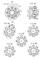
- Fig. 2A to 2E are diagrams for explaining the operation of the multipolar resolver shown in fig. 1 A and 1 B;
- Fig. 3 a diagram for explaining the operating principle of the multipolar resolver shown in figures 1A and 1 B;
- Fig. 4 is a graph showing sin OE which is the sine component of the output voltage of the multipolar resolver shown in figures 1 A and 1 B;
- Fig. 5 is a graph showing sinus 0g which is the sine component of the output voltage of a multipolar resolver according to another embodiment of the invention.
- An embodiment of the multipolar resolver according to the present invention will be described below with reference to figs. 1 A and 1B. In the drawings, the substantially cylindrical rotor 11 made of a magnetic material such as ferrite requiring no coils includes a
rotor shaft 19 and tenrotor poles 12 designated by B1 to B10 equidistantly arranged on the outer periphery thereof. The substantially disc-shape stator 13 of magnetic material such as ferrite includes a protrusion 13A at substantially the central part thereof and eightstator poles 14 designated by P1 to P8 arranged substantially equidistantly on the outer periphery and extending in the same direction as theaxis 19 of the rotor. The stator protrusion 13A is wound with thecentral coil 15, and the bases of the stator poles P2, P4, P6, and P8 are wound withsine coils 16, while the poles P1, P3, P5 and P7 are wound withcosine coils 17. As apparent from the drawings, the poles P2, P4, P6, P8 wound with thesine coils 16 are arranged on the outer periphery of the stator 1.3 alternately with the poles P1, P3, P5, P7 wound with thecosine coils 17. The coils S1, S2, S3 and S4 of the poles P2, P4, P6 and P8 are connected in series with each other. The coils C1, C2, C3 and C4 of the poles P1, P3, P5 and P7 are also connected in series with each other. Thesine coils 16 are connected in series with each other in opposite directions of winding in such a manner that the polarity of the output voltage may be reversed at the electrical angle of 180 degrees. In other words, the sine coils are wound in the counterclockwise direction on the stator poles P2 and P6 and in the clockwise direction on the poles P4 and P8. In similar fashion, thecosine coils 17 are wound on the stator poles P, and P5 in the counterclockwise direction and on the poles P3 and P7 in the clockwise direction. The substantially cylindrical rotor 11 is rotatably arranged in a substantially concave cylindrical space formed by the side walls of the stator protrusion 13A and a plurality ofstator poles 14. The side wall of the stator protrusion 13A is thus arranged in proximity to the side surface of the rotor perpendicular to therotor shaft 19. Also, therotor pole 12 and thestator pole 14 are arranged in proximity to each other. Thestator 13 is preferably formed integrally with thestator poles 14. Themagnetic fluxes 18 generated by the excitation of thecentral coil 15 are thus passed through the stator protrusion 13A,stator 13,stator pole 14,rotor pole 12 and rotor 11 as shown in Fig. 1 B. Although every coil has the same number of turns, the induced voltage of each coil varies depending on the degree of proximity betweenrotor pole 12 andstator pole 14, i.e., the degree of magnetic coupling therebetween. The total of the voltages induced in the coils S1, S2, S3 and S4 shown in the drawing is produced at thesine coil 16. In similar manner, the total of the voltages induced in the shown coils C1, C2, C3 and C4 is obtained at thecosine coil 17. - Next, explanation will be made of the operation for producing an output voltage with the rotation of the resolver upon excitation of the central coil with reference to Figs. 2A to 2E and Fig. 4.
- (1) In the case where the rotor pole B1 is opposed to or aligned with the stator pole P1 (Fig.2A):
- The rotor pole B6 and the stator pole P5 are also aligned with each other so that the degree of magnetic coupling between coils C1 and C3 is maximum, thus producing the maximum voltage. On the other hand, the magnetic coupling between coils C2 and C4 is small, thus producing a minimum voltage. The coils C2 and C4 are wound in the direction opposite to the coils C, and C3, so that the
cosine coil 17 produces the voltage cos θE· sin ωt which is equal to the sum of the voltage across coils C, and C3 less the sum of the voltages across the coils C2 and C4. The degree of magnetic coupling between poles P2 and B2, between poles P4 and B5, between poles P6 and B7 and between poles P8 and B10 are substantially equal to each other. Therefore, the sum of the voltages across coils S1 and S3 less the sum of the voltages across the coils S2 and S4 is substantially zero, so that the output voltage sin θE. sin ωt of thesine coil 16 is zero. - Referring to Fig. 4 showing the value of sin θE which is the sine component of the rotational angle of the rotor, the value of sin θE of the voltage sin θE · sin ωt obtained from the
sin coil 16 when the rotor pole B1 is aligned with stator pole P1 is zero as shown by point A. - (2) In the case where the rotor pole B2 is aligned with stator pole P2 (Fig. 2B):
- In Fig. 2A, the angular displacement between stator pole P2 and rotor pole B2 is 1/40 (=1/8-1/10) of a rotation, i.e., 9 degrees (=45-36 degrees). Thus when the rotor 11 makes 1/40 of a rotation, i.e., 9 degrees from the position shown in Fig. 2A, it achieves the state shown in Fig. 2B. Since the pole B7 is aligned with pole P6 and the coils S, and S3 are coupled magnetically to the greatest degree, a maximum voltage is produced. The coils S2 and S4 are magnetically coupled with each other to the lowest degree, and therefore a minimum voltage is produced therefrom. The coils S2 and S4 are wound in the direction opposite to the coils S, and S3 as described above, so that the
sine coil 16 produces an output voltage sin θE · sin ωt which is equal to the sum of the voltages across the coils S, and S3 less the sum of the voltages across coils S2 and S4. The value of sin θE is shown by point B in Fig. 4. The degree of magnetic coupling between poles P1 and B,, between P3 and B3, between P5 and B6 and between P7 and B8 are substantially equal to each other, with the result that the sum of the voltages across the coils C1 and C3 less the sum of voltages across the coils C2 and C4 is substantially zero. Thus the output voltage cos θE· sin ωt of thecosine coil 17 is substantially zero. - (3) In the case where the rotor pole B3 is aligned with stator pole P3 (Fig. 2C):
- When the rotor 11 makes 1/40 of a rotation or 9 degrees from the position of Fig. 2B, the state shown in Fig. 2C is attained. The pole B8 is also aligned with the pole P7, and the degree of magnetic coupling between coils C2 and C4 is maximum, thus producing the maximum voltage. On the other hand, the degree of magnetic coupling between coils C1 and C3 is lowest and therefore a minimum voltage is produced. Since the coils C1 and C3 are wound in the direction opposite to the direction of coils C2 and C4, the
cosine coil 17 produces an output voltage cos θE· sin ωt which is equal to the sum of the voltages across the coils C2 and C4 less the sum of the voltages across the coils C1 and C3. - In this case, the phase of the output voltage is displaced by 180 degrees from that in the case of Fig. 2A. The degree of magnetic coupling between poles P2 and B2, between P4 and B4, between P6 and B7 and between P8 and B9 are substantially the same. The sum of the voltages across the coils S2 and S4 less the sum of the voltages across the coils S1 and S3 is zero, so that the output voltage sin θE· sin ωt of the
sine coil 16 is substantially zero. The value of sin θE is indicated by point C in Fig. 4. - (4) In the case where rotor pole B4 is aligned with stator pole P4 (Fig. 2D):
- When the rotor 11 makes 1/40 of a rotation from the position of Fig. 2C, the state of Fig. 2D is attained. The pole B9 is also aligned with pole P8 and the degree of magnetic coupling between coils S2 and S4 is maximum, thus producing a maximum voltage. On the other hand, the degree of magnetic coupling between coils S1 and S3 is lowest, and therefore both S1 and S3 produce a minimum voltage. The coils S1 and S3 are wound in the direction opposite to that of the coils S2 and S4, and therefore the
sine coil 16 produces an output voltage sin θE· sin ωt which is the sum of the voltages across the coils S2 and S4 less the sum of voltages across coils S1 and S3. In this case, however, the phase of the output voltage is displaced by 180 degrees from that in the case of Fig. 2B. The value of sin θE is indicated by point D in Fig. 4. The degree of magnetic coupling between P1 and B10, between P3 and B3, between P5 and B5 and between P7 and B8 are substantially equal to each other. The sum of the voltages across the coils C2 and C4 less the sum of the voltages across the coils C, and C3 is substantially zero, so that the output voltage cos θE · sin ωt of thecosine coil 17 is substantially zero. - (5) In the case where the rotor pole B5 is aligned with stator pole P5 (Fig. 2E):
- When the rotor 11 makes 1/40 of a rotation from the position of Fig. 2D, the state of Fig. 2E is attained. The pole B10 is aligned with the pole P,, which is quite the same electrical situation as that shown in Fig. 2A. In other words, the rotor 11 returns to quite the same state electrically as the original state after making 1/10 (=1/40x4) of a rotation as shown progressively in Figs. 2A, 2B, 2C, 2D and 2E in that order, the 1/10 rotation of the rotor 11 being equivalent to the electrical angle of 360 degrees. The value of sin θE is indicated by point E in Fig. 4.
- In the above-mentioned embodiment, the rotor has ten poles, and therefore one mechanical rotation of the rotor 11 corresponds to ten times the electrical angle of 360 degrees, thus indicating a resolver of 20 poles.
- It is seen from the diagram of Fig. 3 for explaining the operating principle that upon excitation of the
central coil 15 by the sine wave of, say, 10 KHz, the rotation of rotor 11 by the mechanical angle of θM causes the output wave forms of cos θE · sin ωt and sin θE · sin ωt to be produced from thecosine coil 17 and thesine coil 16 respectively. The character θE shows an electrical angle, and there is a well-known relation shown below between the mechanical angle θM and the number of poles N.
- In the foregoing embodiment of the present invention, the
central coil 15 is used as the primary coil and thesine coil 16 and thecosine coil 17 as the secondary coil. They may of course be used in reverse way. - Further although the above-mentioned embodiment of the present invention employs eight stator poles and ten rotor poles, it is not limitative but only illustrative. In other words, the number of stator poles n times 4 and the number of rotor
poles n times 5 or 3 may be used alternatively as shown in Table 1 below. It is in order to obtain sine and cosine outputs that the number of stator poles n times 4 is employed.
- An output waveform in a multipolar resolver according to another embodiment is shown in Fig. 5. This voltage waveform represents a sine component of the rotor rotational angle produced by a 12-pole resolver having eight stator poles and 6 rotor poles. As explained above, the multipolar resolver according to the present invention has a coil only on the stator but not on the rotor. This eliminates the need of the slip ring on the one hand and simplifies the general construction on the other hand, leading to many advantages in cost and maintenance.
- Furthermore, by introducing the vernier concept, the fabrication of a multipolar resolver having 20 or more poles is greatly facilitated, resulting in the conspicuous dual advantages of a greater number of divisions available for each rotor rotation and a higher accuracy of each rotor rotation without structural or dimensional limitations. The higher accuracy means that it is no longer necessary to drive the resolver at high speed by raising the gear ratio, leading to the advantage that the resolver may be directly coupled to the motor shaft in numerically controlled machine tool field. Since the resolver according to the present invention is adapted to be directly coupled to the motor shaft without sacrificing the required accuracy, the resolver may be constructed integrally with the motor, thus greatly contributing to a simplified detecting mechanism. Also, the availability of an increased number of divisions makes possible reliable detection of a speed component.
Claims (3)
Applications Claiming Priority (2)
| Application Number | Priority Date | Filing Date | Title |
|---|---|---|---|
| JP11820678A JPS5546862A (en) | 1978-09-25 | 1978-09-25 | Multipolar resolver |
| JP118206/78 | 1978-09-25 |
Publications (2)
| Publication Number | Publication Date |
|---|---|
| EP0009102A1 EP0009102A1 (en) | 1980-04-02 |
| EP0009102B1 true EP0009102B1 (en) | 1983-04-20 |
Family
ID=14730814
Family Applications (1)
| Application Number | Title | Priority Date | Filing Date |
|---|---|---|---|
| EP79102749A Expired EP0009102B1 (en) | 1978-09-25 | 1979-08-01 | A multipolar resolver |
Country Status (5)
| Country | Link |
|---|---|
| US (1) | US4255682A (en) |
| EP (1) | EP0009102B1 (en) |
| JP (1) | JPS5546862A (en) |
| CA (1) | CA1112277A (en) |
| DE (1) | DE2965246D1 (en) |
Cited By (1)
| Publication number | Priority date | Publication date | Assignee | Title |
|---|---|---|---|---|
| DE4113880A1 (en) * | 1991-04-27 | 1992-10-29 | Messerschmitt Boelkow Blohm | TURN SIGNALING SYSTEM |
Families Citing this family (43)
| Publication number | Priority date | Publication date | Assignee | Title |
|---|---|---|---|---|
| EP0013799B1 (en) * | 1978-12-19 | 1985-10-02 | Kabushiki Kaisha Toshiba | Encoder for length or angle measuring devices with high accuracy |
| JPH0753021B2 (en) * | 1983-02-08 | 1995-06-05 | 株式会社安川電機 | Excitation method for phase error compensation of inductor resolver |
| US4697144A (en) * | 1984-04-19 | 1987-09-29 | Verify Electronics Limited | Position sensing apparatus |
| US4605889A (en) * | 1984-08-21 | 1986-08-12 | Resolvex Corporation | Brushless tachometer/synchro |
| USRE32857E (en) * | 1984-08-21 | 1989-02-07 | Resolvex Corporation | Brushless tachometer/synchro |
| US4672347A (en) * | 1985-07-01 | 1987-06-09 | The Charles Stark Draper Laboratory, Inc. | Multi-speed resolver using ferrite stator and rotor structures |
| FR2585124B1 (en) * | 1985-07-17 | 1989-12-01 | Precilec | TWO-POLE POLYPHASE INDUCTIVE SENSOR WITH NON-COIL ROTOR |
| US4631510A (en) * | 1985-09-03 | 1986-12-23 | Powerton, Division Of Contraves Goerz Corporation | Harmonically graded airgap reluctance-type rotating electric resolver |
| US4985691A (en) * | 1986-02-26 | 1991-01-15 | University Of Pittsburgh | Contactless motion sensor |
| DE3618175A1 (en) * | 1986-05-30 | 1987-12-03 | Voest Alpine Automotive | ENCODER |
| FI76898C (en) * | 1987-02-19 | 1988-12-12 | Antti Poro | ELECTRIC MOTOR. |
| US4733117A (en) * | 1987-04-27 | 1988-03-22 | The Superior Electric Company | Reluctance synchro/resolver |
| US4774428A (en) * | 1987-05-15 | 1988-09-27 | Synektron Corporation | Compact three-phase permanent magnet rotary machine having low vibration and high performance |
| US4794511A (en) * | 1988-01-11 | 1988-12-27 | The Superior Electric Company | Apparatus and method for generating two-phase signals for use with a resolver to digital converter |
| FR2647896B1 (en) * | 1989-05-30 | 1991-08-09 | Roulements Soc Nouvelle | ANGULAR POSITION SENSOR AND MULTI-SENSOR APPLICATION DEVICE |
| FR2648632B1 (en) * | 1989-06-16 | 1991-10-04 | Moving Magnet Tech | LOW SIZE SINGLE PHASE ELECTROMAGNETIC ACTUATOR |
| US5164622A (en) * | 1990-06-14 | 1992-11-17 | Applied Motion Products, Inc. | High pole density three phase motor |
| US5512871A (en) * | 1990-12-17 | 1996-04-30 | Moving Magnet Technologies S.A. | Rotatable single-phase electromagnetic actuator |
| GB9110698D0 (en) * | 1991-05-17 | 1991-07-10 | Radiodetection Ltd | Inductive displacement sensors |
| US5404101A (en) * | 1992-02-27 | 1995-04-04 | Logue; Delmar L. | Rotary sensing device utilizing a rotating magnetic field within a hollow toroid core |
| US5763976A (en) * | 1993-12-15 | 1998-06-09 | Parker-Hannifin Corp. | Stator wound resolver with staggered rotor |
| EP0743508A2 (en) * | 1995-05-16 | 1996-11-20 | Mitutoyo Corporation | Induced current position transducer |
| US6002250A (en) * | 1996-05-13 | 1999-12-14 | Mitutoyo Corporation | Electronic linear scale using a self-contained, low-power inductive position transducer |
| US5973494A (en) * | 1996-05-13 | 1999-10-26 | Mitutoyo Corporation | Electronic caliper using a self-contained, low power inductive position transducer |
| US5886519A (en) * | 1997-01-29 | 1999-03-23 | Mitutoyo Corporation | Multi-scale induced current absolute position transducer |
| DE19941464A1 (en) | 1999-09-01 | 2001-03-15 | Hella Kg Hueck & Co | Inductive position sensor |
| JP4375638B2 (en) | 2000-01-25 | 2009-12-02 | 株式会社ハーモニック・ドライブ・システムズ | Absolute position detection method for motor rotation shaft |
| US6630763B1 (en) | 2001-06-11 | 2003-10-07 | Mpc Products Corporation | Solid core angular position resolver |
| JP4034690B2 (en) * | 2003-04-28 | 2008-01-16 | ミネベア株式会社 | Dual variable reluctance resolver and multi-speed resolver system using the same |
| JP2005207914A (en) * | 2004-01-23 | 2005-08-04 | Minebea Co Ltd | Multiplexed resolver |
| JP4142607B2 (en) * | 2004-03-26 | 2008-09-03 | ミネベア株式会社 | Variable reluctance resolver |
| KR100600758B1 (en) * | 2004-09-15 | 2006-07-19 | 엘지전자 주식회사 | Motor's Stator and the Manufacturing Method for the Same |
| US7740593B2 (en) * | 2005-12-09 | 2010-06-22 | Senorx, Inc | Guide block for biopsy or surgical devices |
| KR100943701B1 (en) * | 2008-02-05 | 2010-02-25 | 성삼경 | Electric motor |
| JP2010101716A (en) * | 2008-10-23 | 2010-05-06 | Tamagawa Seiki Co Ltd | Resolver |
| WO2012098841A1 (en) * | 2011-01-20 | 2012-07-26 | 住友金属工業株式会社 | Vehicle body height adjustment valve having resolver for railway carriage |
| US8742715B2 (en) | 2011-06-09 | 2014-06-03 | Simmonds Precision Products, Inc. | System and method for providing control of an electric motor using inductive rotary sensor |
| US9064630B2 (en) * | 2011-10-17 | 2015-06-23 | GM Global Technology Operations LLC | Integrated high frequency rotary transformer and resolver for traction motor |
| EP2853861B1 (en) | 2012-05-14 | 2017-10-18 | Amiteq Co., Ltd. | Position detection device |
| JP5892196B2 (en) * | 2014-01-27 | 2016-03-23 | 日本精工株式会社 | Resolver device, motor and actuator |
| JP6675260B2 (en) * | 2016-04-27 | 2020-04-01 | 東京エレクトロン株式会社 | Transformer, plasma processing apparatus, and plasma processing method |
| JP6630630B2 (en) * | 2016-05-18 | 2020-01-15 | 東京エレクトロン株式会社 | Plasma processing equipment |
| GB2563616B (en) | 2017-06-20 | 2021-03-10 | Dyson Technology Ltd | A stator assembly |
Family Cites Families (10)
| Publication number | Priority date | Publication date | Assignee | Title |
|---|---|---|---|---|
| US2866913A (en) * | 1956-06-27 | 1958-12-30 | Bell Telephone Labor Inc | Multipole pair resolver |
| DE1054354B (en) * | 1957-04-25 | 1959-04-02 | Siemens Ag | Device for generating an electrical signal as a function of angular positions |
| US3265960A (en) * | 1959-10-08 | 1966-08-09 | Benjamin P Blasingame | Capacitive resolver |
| US3041486A (en) * | 1960-04-15 | 1962-06-26 | United Aircraft Corp | Variable reluctance device |
| GB1014116A (en) * | 1963-06-24 | 1965-12-22 | Kabushikikaisha Tokyo Keiki Se | Control signal device for step motor |
| FR1434753A (en) * | 1964-05-25 | 1966-04-08 | S E Lab Engineering Ltd | Improvements to electromechanical transducers |
| US3368142A (en) * | 1965-11-15 | 1968-02-06 | Northrop Corp | Self-testing variable transformer |
| US3641467A (en) * | 1969-05-13 | 1972-02-08 | Allis Chalmers Mfg Co | Rotary inductor |
| US3568119A (en) * | 1969-08-26 | 1971-03-02 | Aeroflex Lab Inc | Dynamic transformer |
| DE2301483C3 (en) * | 1973-01-12 | 1975-10-23 | Okuma Machinery Works, Ltd., Nagoya, Aichi (Japan) | Inductive transducer |
-
1978
- 1978-09-25 JP JP11820678A patent/JPS5546862A/en active Granted
-
1979
- 1979-04-25 CA CA326,329A patent/CA1112277A/en not_active Expired
- 1979-04-30 US US06/034,974 patent/US4255682A/en not_active Expired - Lifetime
- 1979-08-01 EP EP79102749A patent/EP0009102B1/en not_active Expired
- 1979-08-01 DE DE7979102749T patent/DE2965246D1/en not_active Expired
Cited By (1)
| Publication number | Priority date | Publication date | Assignee | Title |
|---|---|---|---|---|
| DE4113880A1 (en) * | 1991-04-27 | 1992-10-29 | Messerschmitt Boelkow Blohm | TURN SIGNALING SYSTEM |
Also Published As
| Publication number | Publication date |
|---|---|
| CA1112277A (en) | 1981-11-10 |
| DE2965246D1 (en) | 1983-05-26 |
| JPS5546862A (en) | 1980-04-02 |
| JPS6243426B2 (en) | 1987-09-14 |
| EP0009102A1 (en) | 1980-04-02 |
| US4255682A (en) | 1981-03-10 |
Similar Documents
| Publication | Publication Date | Title |
|---|---|---|
| EP0009102B1 (en) | A multipolar resolver | |
| JP4002308B2 (en) | Inductive rotational position detector | |
| US3281655A (en) | Inductive multi-speed resolver | |
| JP4862118B2 (en) | Angle detector | |
| US4962331A (en) | Rotatable control signal generator | |
| US4638195A (en) | Multiple-pole stepping motor | |
| JPH06213614A (en) | Position detection device | |
| US4755751A (en) | Brushless rotary position transducer | |
| JP2005164486A (en) | Rotation angle detector | |
| JPH08178611A (en) | Variable reluctance type angle detector | |
| US4629948A (en) | Electric motor and tachometric generator unit | |
| US6137204A (en) | VR-type resolver | |
| EP0144561A1 (en) | Toothed reluctance synchro/resolver | |
| JP2624747B2 (en) | Resolver | |
| JP3429464B2 (en) | Variable reluctance angle detector | |
| US3024409A (en) | Electromagnetic pick-off devices | |
| US4771200A (en) | Synchro generator asymmetric magnetically conductive rotor | |
| JP2548726B2 (en) | Rotation angle detector | |
| JPS62185120A (en) | Resolver | |
| JP2019124514A (en) | Multipolar resolver | |
| JPH0421067Y2 (en) | ||
| JPH0817562B2 (en) | Reluctance resolver | |
| JPH0448142Y2 (en) | ||
| JP2556383B2 (en) | Magnetic resolver | |
| JPH0125289Y2 (en) |
Legal Events
| Date | Code | Title | Description |
|---|---|---|---|
| PUAI | Public reference made under article 153(3) epc to a published international application that has entered the european phase |
Free format text: ORIGINAL CODE: 0009012 |
|
| AK | Designated contracting states |
Designated state(s): CH DE FR GB IT NL SE |
|
| 17P | Request for examination filed |
Effective date: 19800930 |
|
| ITF | It: translation for a ep patent filed |
Owner name: JACOBACCI & PERANI S.P.A. |
|
| GRAA | (expected) grant |
Free format text: ORIGINAL CODE: 0009210 |
|
| AK | Designated contracting states |
Designated state(s): CH DE FR GB IT NL SE |
|
| REF | Corresponds to: |
Ref document number: 2965246 Country of ref document: DE Date of ref document: 19830526 |
|
| ET | Fr: translation filed | ||
| PGFP | Annual fee paid to national office [announced via postgrant information from national office to epo] |
Ref country code: CH Payment date: 19920615 Year of fee payment: 14 |
|
| PGFP | Annual fee paid to national office [announced via postgrant information from national office to epo] |
Ref country code: SE Payment date: 19920818 Year of fee payment: 14 |
|
| ITTA | It: last paid annual fee | ||
| PGFP | Annual fee paid to national office [announced via postgrant information from national office to epo] |
Ref country code: NL Payment date: 19920831 Year of fee payment: 14 |
|
| PG25 | Lapsed in a contracting state [announced via postgrant information from national office to epo] |
Ref country code: SE Effective date: 19930802 |
|
| PG25 | Lapsed in a contracting state [announced via postgrant information from national office to epo] |
Ref country code: CH Effective date: 19930831 |
|
| PG25 | Lapsed in a contracting state [announced via postgrant information from national office to epo] |
Ref country code: NL Effective date: 19940301 |
|
| NLV4 | Nl: lapsed or anulled due to non-payment of the annual fee | ||
| REG | Reference to a national code |
Ref country code: CH Ref legal event code: PL |
|
| EUG | Se: european patent has lapsed |
Ref document number: 79102749.3 Effective date: 19940310 |
|
| PGFP | Annual fee paid to national office [announced via postgrant information from national office to epo] |
Ref country code: GB Payment date: 19970728 Year of fee payment: 19 |
|
| PGFP | Annual fee paid to national office [announced via postgrant information from national office to epo] |
Ref country code: FR Payment date: 19970827 Year of fee payment: 19 |
|
| PGFP | Annual fee paid to national office [announced via postgrant information from national office to epo] |
Ref country code: DE Payment date: 19971031 Year of fee payment: 19 |
|
| PG25 | Lapsed in a contracting state [announced via postgrant information from national office to epo] |
Ref country code: GB Free format text: LAPSE BECAUSE OF NON-PAYMENT OF DUE FEES Effective date: 19980801 |
|
| GBPC | Gb: european patent ceased through non-payment of renewal fee |
Effective date: 19980801 |
|
| PG25 | Lapsed in a contracting state [announced via postgrant information from national office to epo] |
Ref country code: FR Free format text: LAPSE BECAUSE OF NON-PAYMENT OF DUE FEES Effective date: 19990430 |
|
| PG25 | Lapsed in a contracting state [announced via postgrant information from national office to epo] |
Ref country code: DE Free format text: LAPSE BECAUSE OF NON-PAYMENT OF DUE FEES Effective date: 19990601 |
|
| REG | Reference to a national code |
Ref country code: FR Ref legal event code: ST |
|
| PLBE | No opposition filed within time limit |
Free format text: ORIGINAL CODE: 0009261 |
|
| STAA | Information on the status of an ep patent application or granted ep patent |
Free format text: STATUS: NO OPPOSITION FILED WITHIN TIME LIMIT |