EP0010277A1 - Side console for office furniture - Google Patents
Side console for office furniture Download PDFInfo
- Publication number
- EP0010277A1 EP0010277A1 EP19790103951 EP79103951A EP0010277A1 EP 0010277 A1 EP0010277 A1 EP 0010277A1 EP 19790103951 EP19790103951 EP 19790103951 EP 79103951 A EP79103951 A EP 79103951A EP 0010277 A1 EP0010277 A1 EP 0010277A1
- Authority
- EP
- European Patent Office
- Prior art keywords
- side frame
- frame according
- profile
- cable duct
- cable
- Prior art date
- Legal status (The legal status is an assumption and is not a legal conclusion. Google has not performed a legal analysis and makes no representation as to the accuracy of the status listed.)
- Ceased
Links
Images


Classifications
-
- A—HUMAN NECESSITIES
- A47—FURNITURE; DOMESTIC ARTICLES OR APPLIANCES; COFFEE MILLS; SPICE MILLS; SUCTION CLEANERS IN GENERAL
- A47B—TABLES; DESKS; OFFICE FURNITURE; CABINETS; DRAWERS; GENERAL DETAILS OF FURNITURE
- A47B21/00—Tables or desks for office equipment, e.g. typewriters, keyboards
- A47B21/06—Tables or desks for office equipment, e.g. typewriters, keyboards characterised by means for holding, fastening or concealing cables
-
- A—HUMAN NECESSITIES
- A47—FURNITURE; DOMESTIC ARTICLES OR APPLIANCES; COFFEE MILLS; SPICE MILLS; SUCTION CLEANERS IN GENERAL
- A47B—TABLES; DESKS; OFFICE FURNITURE; CABINETS; DRAWERS; GENERAL DETAILS OF FURNITURE
- A47B17/00—Writing-tables
-
- H—ELECTRICITY
- H02—GENERATION; CONVERSION OR DISTRIBUTION OF ELECTRIC POWER
- H02G—INSTALLATION OF ELECTRIC CABLES OR LINES, OR OF COMBINED OPTICAL AND ELECTRIC CABLES OR LINES
- H02G3/00—Installations of electric cables or lines or protective tubing therefor in or on buildings, equivalent structures or vehicles
- H02G3/02—Details
- H02G3/04—Protective tubing or conduits, e.g. cable ladders or cable troughs
- H02G3/0437—Channels
Definitions
- the invention relates to a side frame according to the preamble of claim 1.
- connection cables Because of the diverse use of electrical devices, such as typewriters, calculating machines, message transmission units, connection units for data processing systems and the like, in offices, a large number of connection cables often have to be laid there.
- the connecting cables are usually led from wall or floor sockets to the respective workplaces. So that the large number of cables are not lying around or hanging freely, it is common to place the cables in vertical cable channels, e.g. in the side frame of the desks to the level of the immediate work area.
- the cable duct should be closed off or concealed, particularly for aesthetic reasons. However, since the cable routing needs to be changed more often or new cables routed, the cable duct should be easily accessible for this handling.
- the laying of three cables of different cross-sections next to each other is required. However, these must be arranged in the cable duct and be easy to lay.
- the invention is intended to meet the needs outlined above with little design effort.
- the side frame can be used on the right and left, i.e. be equally accessible from both sides for cable laying.
- the inventive concept laid down in the main claim can be implemented in a simple manner in terms of construction with the measure of claim 2, the stability of the elements delimiting the cable duct, such as struts or the like, being increased.
- the Z profile and subdivision profile form a fixed unit.
- a structurally simple solution for easy removal and attachment of the cap is provided according to claim 8.
- the exposed outside of side frames should also be completely closed or covered in the area of the vertical cable duct, while in the case of adjacent side frames of adjacent desks and horizontally continuous cable routing, a lateral outlet for the cables at the upper end of the vertical cable duct must be kept free. In order to be able to easily implement these alternatives, the measure of claim 10 has been taken.
- the already existing cams of the upper end cap are used at the same time for releasably fixing the upper cover element.
- the side frame - 1 of a desk is designed as an n-frame, in whose vertical strut 22 a vertical cable duct 2 is formed.
- the cable duct 2 is delimited by two square tubes 23, which are arranged at a distance from one another at the lower end, between the side wall surfaces 6 facing one another.
- the vertical cable duct 2 is diagonally divided into two approximately wedge-shaped vertical cable duct sections 3 and 4 by a Z-profile 5 extending essentially over the entire height of the cable duct 2, which complement each other to form the overall cross section of the cable duct 2.
- the Z-profile 5 is attached to the free legs on the side wall surfaces 6, for example welded to them when both the square tubes 23 a's and the Z-profile 5 are made of metal.
- a dividing profile 8, for example made of plastic, with outward-pointing ribs 7 divides the channel sections 3 and 4 into vertically adjacent cable chambers 9, 10 and 11.
- the cable with the largest cross-section can , in the cable chamber 10 with the medium cross section and in the cable chamber 11 with the smallest cross section side by side.
- the ribs 7 are provided on their outer longitudinal edges with locking grooves, in which inward-pointing resilient clamping lugs 13 of side cover plates 12, which are also made of plastic, for example, are attached.
- the respective cover plate 12 rests with its outer vertical longitudinal edges on the one hand on one leg of the Z profile 5 and on the other hand on the outer edge of an outer rib 24 of the subdivision profile 8; so that the outer surface of the cover plate 12 is flush with the adjacent square tubes 23, the leg and the rib 24 are set back according to the thickness of the cover plate 12.
- a swiveling flap 14 according to FIGS. 6a and 6b is provided at the lower end of at least one cover plate 12, which has a correspondingly smaller vertical length, for the exit or entry of the cables into the vertical cable duct 2.
- the flap 14 consists essentially of a plate part 25, from which project at its lower edge inwardly tapered side legs 26. On the side legs 26, laterally outward elevations or cams 27 are formed, by means of which the flap 14 can be pivoted in corresponding recesses or
- the flap 14 can therefore be made in one piece from plastic.
- the cover plates 12 do not extend to the upper edge of the cable duct 2 open at the top. Rather, an end cap 15 can be inserted into the cable duct 2 from above, which is connected in more detail in FIGS. 4a and 4b.
- the cap 15 has a head section 28, from which elastically resilient tabs 18 project downward.
- the tabs 18 are adjacent to the side wall surfaces 6 which delimit the cable duct 2.
- the tabs 18 with cams 16 snap into corresponding holes or recesses 17 in the side wall surfaces 6.
- two tabs 16 are arranged one above the other on each tab, of which the upper tapers conically and the lower tapered only at the lower edge is.
- end cap 15 can be easily inserted into the cable duct from above under low pressure.
- extraction is only possible if the two tabs 18 are pressed inwards by hand at the lower edge. To facilitate the engagement, the tabs 18 are therefore bent inwards at the lower end towards the central plane of the cap 15.
- the end cap 15 can also be made in one piece from plastic.
- the part of the vertical cable duct 2 which is still exposed after the end cap 15 has been placed over the cover plates, where no cables have to be led out, can be closed off by a separate cover element 19.
- the cover element 19 consists of a base plate 29, from which side cheeks 20 point into the interior of the channel. In the cheeks 20 there are at least one of clamping lips 21 laterally limited indentations 30 are kept free, with the aid of which the respective cover element 19 can be plugged onto the cams 16 of the end cap 15. These cover elements 19 can therefore each be dismantled and attached without the need for special tools.
Abstract
Description
Die Erfindung betrifft ein Seitengestell nach dem Gattungsbegriff des Anspruchs 1.The invention relates to a side frame according to the preamble of claim 1.
Wegen der vielfältigen Verwendung elektrischer Geräte, wie Schreibmaschinen, Rechenmaschinen, Nachrichtenübermittlungseinheiten, Anschlußeinheiten für Datenverarbeitungsanlagen und dergleichen, in Büroräumen muß dort häufig eine Vielzahl von Anschlußkabeln verlegt werden. Die Anschlußkabel sind dabei üblicherweise von Wand- oder Bodensteckdosen zu den jeweiligen Arbeitsplätzen geführt. Damit die Vielzahl der Kabel nicht frei herumliegt oder -hängt, ist es üblich, die Kabel in vertikalen Kabelkanälen z.B. in dem Seitengestell der Schreibtische auf die Höhe des unmittelbaren Arbeitsbereiches zu führen. Die Unterbringung soll trotz unterschiedlicher Kabelquerschnitte bequem und raumsparend sein. Der Kabelkanal soll dabei insbesondere aus ästhetischen Gründen nach außen abgeschlossen bzw. verdeckbar sein. Da aber die Kabelverlegung häufiger geändert oder auch neue Kabel verlegt werden müssen, soll der Kabelkanal für diese Handhabungen einfach zugänglich sein. Üblicherweise wird insbesondere bei der Anwendung von Datenverarbeitungsanlagen die Verlegung von drei Kabeln unterschiedlichen Querschnitts nebeneinander verlangt. Diese müssen aber in dem Kabelkanal geordnet und einfach verlegbar sein.Because of the diverse use of electrical devices, such as typewriters, calculating machines, message transmission units, connection units for data processing systems and the like, in offices, a large number of connection cables often have to be laid there. The connecting cables are usually led from wall or floor sockets to the respective workplaces. So that the large number of cables are not lying around or hanging freely, it is common to place the cables in vertical cable channels, e.g. in the side frame of the desks to the level of the immediate work area. Despite the different cable cross-sections, the accommodation should be comfortable and space-saving. The cable duct should be closed off or concealed, particularly for aesthetic reasons. However, since the cable routing needs to be changed more often or new cables routed, the cable duct should be easily accessible for this handling. Usually, especially when using data processing systems, the laying of three cables of different cross-sections next to each other is required. However, these must be arranged in the cable duct and be easy to lay.
Die Erfindung soll den zuvor geschilderten Bedürfnissen mit geringem konstruktiven Aufwand Rechnung tragen. Dabei soll das Seitengestell rechts wie links verwendbar, d.h. von beiden Seiten für die Kabelverlegung gleichermaßen zugänglich sein.The invention is intended to meet the needs outlined above with little design effort. The side frame can be used on the right and left, i.e. be equally accessible from both sides for cable laying.
Diese Aufgabe wird mit dem Merkmal des kennzeichnenden Teils des Anspruchs 1 gelöst. Die Unterteilung des vertikalen Kabelkanals in zwei im horizontalen Querschnitt etwa keilförmige Kanalabschnitte gewährleistet eine einfache Verlegbarkeit der drei Kabel unterschiedlicher Querschnitte sowohl von der rechten als auch von der linken Seite des Seitengestells her bei optimaler Ausnutzung des Kabelkanalquerschnittes.This object is achieved with the feature of the characterizing part of claim 1. The subdivision of the vertical cable duct into two channel sections that are approximately wedge-shaped in the horizontal cross section ensures that the three cables of different cross sections can be laid easily both from the right and from the left side of the side frame with optimal use of the cable duct cross section.
Der im Hauptanspruch niedergelegte Erfindungsgedanke läßt sich konstruktiv auf einfache Weise mit der Maßnahme des Anspruchs 2 verwirklichen, wobei die Stabilität der den Kabelkanal begrenzenden Elemente, wie Streben oder dergl. erhöht wird.The inventive concept laid down in the main claim can be implemented in a simple manner in terms of construction with the measure of claim 2, the stability of the elements delimiting the cable duct, such as struts or the like, being increased.
Mit Hilfe des nach Anspruch 3 vorgesehenen Unterteilungsprofiles wird die- Verlegung der vorzugsweise drei Kabel unterschiedlichen Querschnittes in den einzelnen vertikalen Kabelkammern noch erleichtert.With the help of the subdivision profile provided according to
Nach der Maßnahme des Anspruchs 4 bilden Z-Profil und Unterteilungsprofil eine feste Einheit.According to the measure of claim 4, the Z profile and subdivision profile form a fixed unit.
Bei einer besonderen Ausgestaltung der Erfindung gemäß Anspruch 5 werden die vertikalen Rippen des Unterteilungsprofiles außer für ihre Funktion zur Unterteilung der Kanalabschnitte in vertikale Käbelkammern zur Aufklemmung und Festlegung von Abdeckplatten ausgenutzt. Für das Abnehmen und Aufklemmen der Abdeckplatten sind somit keine Werkzeuge erforderlich.In a special embodiment of the invention according to claim 5, the vertical ribs of the subdivision profile are used in addition to their function to subdivide the channel sections into vertical kebab chambers for clamping and fixing cover plates. No tools are required for removing and clamping the cover plates.
Am unteren Ende des vertikalen Kabelkanals sind die Kabel in den Kabelkanal einzuführen. Um dies auf einfache Weise ohne Abnehmen der gesamten Abdeckplatte bewerkstelligen zu können, ist die Maßnahme des Anspruchs 6 getroffen. Die ausschwenkbare Klappe läßt sich einfach von Hand öffnen. Am oberen Ende des vertikalen Kabelkanals treten entweder die Kabel aus oder sie werden in einem sich anschließenden horizontalen Kabelkanal zu den benachbarten Arbeitsplätzen geführt. Bei der Verlegung der Kabel ist es jedenfalls notwendig, den Kabelkanal am oberen Ende so weit zu öffnen, so daß die erforderlichen Handhabungen für das Durchziehen der Kabel vorgenommen werden können. Diesem Zweck dient die Maßnahme des Anspruchs 7.At the lower end of the vertical cable duct, the cables must be inserted into the cable duct. In order to be able to do this in a simple manner without removing the entire cover plate, the measure of
Eine konstruktiv einfache Lösung für das leichte Abnehmen und Aufstecken der Kappe ist nach Anspruch 8 vorgesehen.A structurally simple solution for easy removal and attachment of the cap is provided according to claim 8.
Die Maßnahme des Anspruchs 9 sorgt für einen zuverlässigen Sitz bei Lösbarkeit der Kappe von Hand.The measure of
Die freiliegende Außenseite von Seitengestellen soll auch im Bereich des vertikalen Kabelkanals möglichst vollständig verschlossen bzw. abgedeckt sein, während bei einander grenzenden Seitengestellen benachbarter Schreibtische und horizontal durchgehender Kabelführung ein seitlicher Austritt für die Kabel am oberen Ende des vertikalen Kabelkanals freigehalten bleiben muß. Um diese Alternativen einfach verwirklichen zu können, ist die Maßnahme des Anspruchs 10 getroffen.The exposed outside of side frames should also be completely closed or covered in the area of the vertical cable duct, while in the case of adjacent side frames of adjacent desks and horizontally continuous cable routing, a lateral outlet for the cables at the upper end of the vertical cable duct must be kept free. In order to be able to easily implement these alternatives, the measure of claim 10 has been taken.
Bei dem Merkmal des Anspruchs 11 werden die ohnehin vorhandenen Nocken der oberen Abschlußkappe gleichzeitig zur lösbaren Festlegung des oberen Abdeckelementes benutzt.In the feature of
Weitere Merkmale, Vorteile und Anwendungsmöglichkeiten der vorliegenden Erfindung ergeben sich aus der nachfolgenden Beschreibung eines Ausführungsbeispieles anhand der beiliegenden Zeichnung. Dabei bilden alle beschriebenen und/oder bildlich dargestellten Merkmale für sich oder in beliebiger sinnvoller Kombination auch unabhängig von ihrer Zusammenfassung in den Ansprüchen oder deren Rückbeziehung den Gegenstand der vorliegenden Erfindung.Further features, advantages and possible uses of the present invention result from the following description of an exemplary embodiment with reference to the accompanying drawing. All of the features described and / or depicted form the subject matter of the present invention individually or in any meaningful combination, regardless of their combination in the claims or their relationship.
Es zeigen:
- Fig. 1 in Schrägansicht ein nach der Erfindung ausgestattetes Seitengestell an einem Schreibtisch,
- Fig. 2 eine Schrägansicht gemäß Fig. 1 in Explosionsdarstellung,
- Fig. 3 einen horizontalen Schnitt durch das erfindungsgemäße Seitengestell im Bereich des vertikalen Kabelkanals,
- Fig. 4 die obere Verschlußkappe des vertikalen Kabelkanals im Schnitt bzw. in Ansicht (Fig. 4a) und Seitenansicht (Fig. 4b),
- Fig. 5 im Vertikalschnitt das obere Abdeckelement, und
- Fig. 6 die am unteren Ende des vertikalen Kabelkanals ausschwenkbare Klappe in einer teilweise weggebrochenen Ansicht (Fig. 6a) und Seitenansicht(Fig.6b).
- 1 in an oblique view a side frame equipped according to the invention on a desk,
- 2 is an oblique view of FIG. 1 in an exploded view,
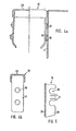
- 3 shows a horizontal section through the side frame according to the invention in the region of the vertical cable duct,
- 4 the upper sealing cap of the vertical cable duct in section or in view (FIG. 4a) and side view (FIG. 4b),
- Fig. 5 in vertical section, the upper cover, and
- 6 the flap which can be swung out at the lower end of the vertical cable duct in a partially broken away view (FIG. 6a) and side view (FIG. 6b).
Nach Fig. 1 und 2 ist das Seitengestell-1 eines Schreibtisches als n-Gestell ausgebildet, in dessen einer vertikalen Strebe 22 ein vertikaler Kabelkanal 2 gebildet ist. Der Kabelkanal 2 ist durch zwei im Abstand angeordnete am unteren Ende miteinander verbundene Vierkantrohre 23, und zwar zwischen dessen einander zugewandten Seitenwandflächen 6 begrenzt. Der vertikale Kabelkanal 2 wird durch ein im wesentlichen über die gesamte Höhe des Kabelkanals 2 sich erstreckendes Z-Profil 5 diagonal in zwei etwa keilförmige vertikale Kabelkanalabschnitte 3 und 4 unterteilt, die sich zu dem Gesamtquerschnitt des Kabelkanals 2 ergänzen. Das Z-Profil 5 ist mit den freien Schenkeln an den Seitenwandflächen 6 befestigt, z.B. mit diesen verschweißt, wenn sowohl die Vierkantrohre 23 a's auch das Z-Profil 5 aus Metall bestehen. Auf jeder Seite des Z-PrQfils 5 unterteilt ein beispielsweise aus Kunststoff bestehendes Unterteilungsprofil 8 mit auswärts weisenden Rippen 7 die Kanalabschnitte 3 und 4 je in vertikal nebeneinander verlaufende Kabelkammern 9, 10 und 11. In der jeweiligen Kabelkammer 9 kann das Kabel mit dem größten Querschnitt, in der Kabelkammer 10 mit dem mittleren Querschnitt und in der Kabelkammer 11 mit dem geringsten Querschnitt nebeneinander untergebracht werden. Die Rippen 7 sind an ihren äußeren Längsrändern mit Rastnuten versehen, in welche nach innen weisende federnde Klemmnasen 13 von seitlichen Abdeckplatten 12, die z.B. ebenfalls aus Kunststoff bestehen, angebracht sind. Beim Aufstecken der Abdeckplatten 12 und Zusammenwirken der Rippen 7 und Klemmnasen 13 liegt die jeweilige Abdeckplatte 12 mit ihren äußeren vertikalen Längsrändern einerseits an dem einen Schenkel des Z-Profils 5, andererseits an dem äußeren Rand einer Außenrippe 24 des Unterteilungsprofiles 8 an; damit die Außenfläche der Abdeckplatte 12 bündig mit den angrenzenden Vierkantrohren 23 liegt, sind der genannte Schenkel und die Rippe 24 entsprechend der Dicke der Abdeckplatte 12 zurückgesetzt.1 and 2, the side frame - 1 of a desk is designed as an n-frame, in whose vertical strut 22 a vertical cable duct 2 is formed. The cable duct 2 is delimited by two
Für den Austritt bzw. den Eintritt der Kabel in den vertikalen Kabelkanal 2 ist am unteren Ende wenigstens einer Abdeckplatte 12, die entsprechend geringere vertikale Länge hat, eine ausschwenkbare Klappe 14 gemäß Fig. 6a und 6b vorgesehen. Die Klappe 14 besteht im wesentlichen aus einem Plattenteil 25, von welchem an ihrem unteren Rande nach innen abgeschrägte Seitenschenkel 26 wegragen. An die Seitenschenkel 26 sind jeweils seitlich auswärts weisende Erhebungen oder Nocken 27 angeformt, mit Hilfe derer die Klappe 14 schwenkbar in entsprechenden Vertiefungen bzw.A
Aussparungen der Seitenwandflächen 6 der Vierkantrohre 23 gehalten ist. Die Klappe 14 kann demnach einstückig aus Kunststoff gefertigt sein.Recesses of the
Die Abdeckplatten 12 reichen, wie aus Fig. 1 ersichtlich, nicht bis zum oberen Rand des oben offenen Kabelkanals 2. Vielmehr ist von oben in den Kabelkanal 2 eine Abschlußkappe 15 einsteckbar-, die in den Fig. 4a und 4b näher veranschlauchlicht ist. Die Kappe 15 hat einen Kopfabschnitt 28, von welchem nach unten elastisch federnde Laschen 18 wegragen. Die Laschen 18 liegen im eingebauten Zustand den Seitenwandflächen 6, die den Kabelkanal 2 begrenzen, benachbart. Beim Einfügen rasten die Laschen 18 mit Nocken 16 in entsprechende Löcher oder Aussparungen 17 in den Seitenwandflächen 6. Gemäß der Darstellung sind an jeder Lasche 18-zwei Nocken 16 übereinander angeordnet, von welchen die obere sich kegelförmig verjüngt und die untere lediglich am unteren Rand abgeschrägt ist. Hierdurch wird erreicht, daß die Abschlußkappe 15 zwar einfach unter geringem Druck von oben in den Kabelkanal eingesetzt werden kann. Ein Herausziehen ist aber nur möglich, wenn die beiden Laschen 18 am unteren Rand yon Hand nach innen gedrückt werden. Zur Erleichterung des Eingriffs sind deswegen die Laschen 18 am unteren Ende zur Mittelebene der Kappe 15 hin einwärts gebogen. Auch die Abschlußkappe 15 kann einstückig aus Kunststoff gefertigt sein.As can be seen from FIG. 1, the
Der nach dem Aufsetzen der Abschlußkappe 15 noch über den Abdeckplatten freiliegende Teil des vertikalen Kabelkanals 2 kann, wo keine Kabel herausgeführt werden müssen, durch ein gesondertes Abdeckelement 19 verschlossen werden. Das Abdeckelement 19 besteht aus einer Grundplatte 29, von welchem aus seitliche Wangen 20 ins Kanalinnere weisen. In den Wangen 20 sind von Klemmlippen 21 wenigstens einseitig begrenzte Einbuchtungen 30 freigehalten, mit Hilfe derer das jeweilige Abdeckelement 19 auf die Nocken 16 der Abschlußkappe 15 aufgesteckt werden kann. Diese Abdeckelemente 19 können also je für sich ab- und angebaut werden, ohne daß dafür besondere Werkzeuge erforderlich wären.The part of the vertical cable duct 2 which is still exposed after the
- 1 Seitengestell1 side frame
- 2 Kabelkanal2 cable channels
- 3 Kanalabschnitt3 channel section
- 4 Kanalabschnitt4 channel section
- 5 Profil5 profile
- 6 Seitenwandfläche6 side panel
- 7 Rippen7 ribs
- 8 Unterteilungsprofil8 subdivision profile
- 9 Kanalkammer9 channel chamber
- 10 Kanalkammer10 channel chamber
- 11 Kanalkammer11 channel chamber
- 12 Abdeckplatte12 cover plate
- 13 Klemmnase13 clamping nose
- 14 Klappe14 flap
- 15 Kappe15 cap
- 16 Nocken16 cams
- 17 Aussparung17 recess
- 18 Laschen18 tabs
- 19 Abdeckelement19 cover element
- 20 Wangen ,20 cheeks,
- 21 Klemmlippen21 clamping lips
- 22 Strebe22 strut
- 23 Vierkantrohre23 square tubes
- 24 Außenrippe24 outer rib
- 25 Plattenteil25 plate part
- 26 Seitenschenkel26 side legs
- 27 Erhebungen27 surveys
- 28 Kopfabschnitt28 head section
- 29 Grundplatte29 base plate
- 30 Aussparungen30 recesses
Claims (11)
Applications Claiming Priority (2)
| Application Number | Priority Date | Filing Date | Title |
|---|---|---|---|
| DE7831543U | 1978-10-23 | ||
| DE19787831543 DE7831543U1 (en) | 1978-10-23 | 1978-10-23 | SIDE FRAME FOR OFFICE FURNITURE |
Publications (1)
| Publication Number | Publication Date |
|---|---|
| EP0010277A1 true EP0010277A1 (en) | 1980-04-30 |
Family
ID=6696299
Family Applications (1)
| Application Number | Title | Priority Date | Filing Date |
|---|---|---|---|
| EP19790103951 Ceased EP0010277A1 (en) | 1978-10-23 | 1979-10-15 | Side console for office furniture |
Country Status (2)
| Country | Link |
|---|---|
| EP (1) | EP0010277A1 (en) |
| DE (2) | DE7831543U1 (en) |
Cited By (15)
| Publication number | Priority date | Publication date | Assignee | Title |
|---|---|---|---|---|
| GB2139488A (en) * | 1983-05-11 | 1984-11-14 | Mines & West Ltd | Improvements in and relating to desking systems |
| US4612863A (en) * | 1982-10-23 | 1986-09-23 | Voko Franz Vogt & Co. | Work table |
| GB2180149A (en) * | 1985-09-05 | 1987-03-25 | Arenson Int Ltd | Desk |
| US4688748A (en) * | 1985-08-13 | 1987-08-25 | Ahrend Groep B.V. | Support construction for desk- or table-top |
| EP0236809A2 (en) * | 1986-03-10 | 1987-09-16 | VS Vereinigte Spezialmöbelfabriken Verwaltungs-GmbH | Work-table for equipment, in particular a computer system |
| US4734826A (en) * | 1986-03-10 | 1988-03-29 | Haworth, Inc. | Work surface with channel for power communication cabling |
| EP0398014A1 (en) * | 1989-05-17 | 1990-11-22 | OTTO LAMPERTZ, FABRIKEN FÜR ORGANISATIONSMITTEL UND EDV-ZUBEHÖR GMBH & CO. KG | Variable work place furniture system |
| WO1991016835A1 (en) * | 1990-05-02 | 1991-11-14 | 3K Büromöbel Gmbh | Side-member for office furniture |
| EP0462920A1 (en) * | 1990-06-18 | 1991-12-27 | Mobel Linea, S.L. | Structure for the formation of office furniture and the like |
| GB2247613A (en) * | 1990-09-07 | 1992-03-11 | Martina Limited | A frame for a desk |
| GB2337453A (en) * | 1998-05-01 | 1999-11-24 | Ditto Sales Inc | Cable management apparatus for furniture leg. |
| WO1999065126A1 (en) * | 1998-06-12 | 1999-12-16 | Giuseppe Formuso | Elements to cover cables, cases, shells, panels, and channel to cover cables, particularly for electric and/or electronic apparatuses used on a working plane |
| US6216606B1 (en) * | 1998-03-10 | 2001-04-17 | Jayashree R. Kathardekar | Article of furniture |
| US6254206B1 (en) * | 1999-02-16 | 2001-07-03 | Bretford Manufacturing, Inc. | Wire manager |
| US6732661B2 (en) * | 2001-10-11 | 2004-05-11 | Sedus Stoll Ag | Moving table flap |
Families Citing this family (6)
| Publication number | Priority date | Publication date | Assignee | Title |
|---|---|---|---|---|
| US4762072A (en) * | 1986-10-07 | 1988-08-09 | Westinghouse Electric Corp. | Desk and space dividing wall panel assembly |
| US4843707A (en) * | 1987-08-19 | 1989-07-04 | Sanders Associates, Inc. | Cable retention system |
| US5709156A (en) * | 1995-06-07 | 1998-01-20 | Krueger International, Inc. | Flip-up electrical and communications device for use in combination with a worksurface |
| US5673632A (en) * | 1996-01-03 | 1997-10-07 | Sykes; Christopher C. | Workstation having L-shaped worktop and flat-folding legs |
| US6327983B1 (en) * | 1999-03-03 | 2001-12-11 | Steelcase Development Corporation | Conference table with central utility system |
| US6979209B2 (en) | 2003-01-29 | 2005-12-27 | Krueger International, Inc. | Biased utility receptacle assembly |
Citations (2)
| Publication number | Priority date | Publication date | Assignee | Title |
|---|---|---|---|---|
| US1786823A (en) * | 1927-03-17 | 1930-12-30 | Westinghouse Electric & Mfg Co | Desk |
| FR1561565A (en) * | 1968-03-27 | 1969-03-28 |
-
1978
- 1978-10-23 DE DE19787831543 patent/DE7831543U1/en not_active Expired
-
1979
- 1979-04-20 DE DE19792916002 patent/DE2916002A1/en not_active Ceased
- 1979-10-15 EP EP19790103951 patent/EP0010277A1/en not_active Ceased
Patent Citations (2)
| Publication number | Priority date | Publication date | Assignee | Title |
|---|---|---|---|---|
| US1786823A (en) * | 1927-03-17 | 1930-12-30 | Westinghouse Electric & Mfg Co | Desk |
| FR1561565A (en) * | 1968-03-27 | 1969-03-28 |
Cited By (18)
| Publication number | Priority date | Publication date | Assignee | Title |
|---|---|---|---|---|
| US4612863A (en) * | 1982-10-23 | 1986-09-23 | Voko Franz Vogt & Co. | Work table |
| GB2139488A (en) * | 1983-05-11 | 1984-11-14 | Mines & West Ltd | Improvements in and relating to desking systems |
| US4688748A (en) * | 1985-08-13 | 1987-08-25 | Ahrend Groep B.V. | Support construction for desk- or table-top |
| GB2180149A (en) * | 1985-09-05 | 1987-03-25 | Arenson Int Ltd | Desk |
| GB2180149B (en) * | 1985-09-05 | 1990-01-24 | Arenson Int Ltd | Improvements in desks |
| EP0236809A2 (en) * | 1986-03-10 | 1987-09-16 | VS Vereinigte Spezialmöbelfabriken Verwaltungs-GmbH | Work-table for equipment, in particular a computer system |
| US4734826A (en) * | 1986-03-10 | 1988-03-29 | Haworth, Inc. | Work surface with channel for power communication cabling |
| EP0236809A3 (en) * | 1986-03-10 | 1988-07-20 | VS Vereinigte Spezialmöbelfabriken Verwaltungs-GmbH | Work-table for equipment, in particular a computer system |
| EP0398014A1 (en) * | 1989-05-17 | 1990-11-22 | OTTO LAMPERTZ, FABRIKEN FÜR ORGANISATIONSMITTEL UND EDV-ZUBEHÖR GMBH & CO. KG | Variable work place furniture system |
| WO1991016835A1 (en) * | 1990-05-02 | 1991-11-14 | 3K Büromöbel Gmbh | Side-member for office furniture |
| EP0462920A1 (en) * | 1990-06-18 | 1991-12-27 | Mobel Linea, S.L. | Structure for the formation of office furniture and the like |
| GB2247613A (en) * | 1990-09-07 | 1992-03-11 | Martina Limited | A frame for a desk |
| US6216606B1 (en) * | 1998-03-10 | 2001-04-17 | Jayashree R. Kathardekar | Article of furniture |
| GB2337453A (en) * | 1998-05-01 | 1999-11-24 | Ditto Sales Inc | Cable management apparatus for furniture leg. |
| GB2337453B (en) * | 1998-05-01 | 2002-01-16 | Ditto Sales Inc | Wire management apparatus |
| WO1999065126A1 (en) * | 1998-06-12 | 1999-12-16 | Giuseppe Formuso | Elements to cover cables, cases, shells, panels, and channel to cover cables, particularly for electric and/or electronic apparatuses used on a working plane |
| US6254206B1 (en) * | 1999-02-16 | 2001-07-03 | Bretford Manufacturing, Inc. | Wire manager |
| US6732661B2 (en) * | 2001-10-11 | 2004-05-11 | Sedus Stoll Ag | Moving table flap |
Also Published As
| Publication number | Publication date |
|---|---|
| DE2916002A1 (en) | 1980-11-13 |
| DE7831543U1 (en) | 1979-02-15 |
Similar Documents
| Publication | Publication Date | Title |
|---|---|---|
| EP0010277A1 (en) | Side console for office furniture | |
| DE4207281C1 (en) | ||
| DE2927114A1 (en) | SHELVING SYSTEM | |
| DE102006058779A1 (en) | cabinet arrangement | |
| EP0706012A1 (en) | Cooking device | |
| DE2256853A1 (en) | DRAWER CABINET WITH SLIDING TRACKS FOR SLIDING DRAWERS OR DRAWERS | |
| DE2625202C3 (en) | Household appliance, e.g. dishwasher, with a base recess on the front | |
| CH677708A5 (en) | ||
| DE19610347C1 (en) | Cable ducting system e.g. for office equipment, particularly computer work stations | |
| WO1996024236A1 (en) | Switch cabinet with rack and mounting plate | |
| WO2000024102A1 (en) | Assembly for cable conduits of a piece of workstation furniture | |
| EP0092104B1 (en) | Rack with card frames fittable by means of side slide guides | |
| EP0236809A2 (en) | Work-table for equipment, in particular a computer system | |
| DE10007431A1 (en) | Partitioning office space to create discrete and separate office units | |
| DE10103934C2 (en) | cabinet system | |
| DE3333463A1 (en) | Multi-purpose cabinet | |
| DE3142858A1 (en) | Wall unit or shelving unit having a base and having compartments to receive electrical appliances, in particular media relay appliances or the like | |
| EP0102582A1 (en) | Mains connectable desk, especially for office work | |
| EP1145666B1 (en) | Shelf, in particular for libraries | |
| DE2350354A1 (en) | Universal front panel for drawers of different heights - comprises interfitting symmetrical end parts and spacer members | |
| DE4205293A1 (en) | Cabling duct for switch cabinets - uses semi-closed rectangular section conduit with slits in sides and top lips and unslotted cover plate | |
| DE10112000C1 (en) | equipment cabinet | |
| DE2216129A1 (en) | WORK TABLE WITH ELECTRICAL LINES IN THE TABLE | |
| DE2328235C3 (en) | Multipurpose installation duct for laying walls, in particular for building electrical installations | |
| DE10328405B4 (en) | switch cabinet |
Legal Events
| Date | Code | Title | Description |
|---|---|---|---|
| PUAI | Public reference made under article 153(3) epc to a published international application that has entered the european phase |
Free format text: ORIGINAL CODE: 0009012 |
|
| AK | Designated contracting states |
Designated state(s): AT BE CH FR GB IT LU NL SE |
|
| 17P | Request for examination filed | ||
| STAA | Information on the status of an ep patent application or granted ep patent |
Free format text: STATUS: THE APPLICATION HAS BEEN REFUSED |
|
| 18R | Application refused |
Effective date: 19840518 |
|
| RIN1 | Information on inventor provided before grant (corrected) |
Inventor name: BITTERBERG, KARL-GEORG, PROF. Inventor name: KRAETSCHMER, SIEGFRIED |