EP0010885A1 - Computerized tomographic apparatus - Google Patents
Computerized tomographic apparatus Download PDFInfo
- Publication number
- EP0010885A1 EP0010885A1 EP79302180A EP79302180A EP0010885A1 EP 0010885 A1 EP0010885 A1 EP 0010885A1 EP 79302180 A EP79302180 A EP 79302180A EP 79302180 A EP79302180 A EP 79302180A EP 0010885 A1 EP0010885 A1 EP 0010885A1
- Authority
- EP
- European Patent Office
- Prior art keywords
- signals
- paths
- overlap zone
- detectors
- overlap
- Prior art date
- Legal status (The legal status is an assumption and is not a legal conclusion. Google has not performed a legal analysis and makes no representation as to the accuracy of the status listed.)
- Granted
Links
- 230000005855 radiation Effects 0.000 claims abstract description 16
- 238000012935 Averaging Methods 0.000 claims abstract description 6
- 238000010606 normalization Methods 0.000 claims abstract description 4
- 238000010894 electron beam technology Methods 0.000 claims description 5
- 238000009826 distribution Methods 0.000 claims description 4
- 230000000149 penetrating effect Effects 0.000 claims description 4
- 230000000694 effects Effects 0.000 abstract description 3
- 230000002411 adverse Effects 0.000 abstract 2
- 238000000034 method Methods 0.000 description 7
- 238000012545 processing Methods 0.000 description 7
- 230000033001 locomotion Effects 0.000 description 4
- 238000010586 diagram Methods 0.000 description 3
- 238000004519 manufacturing process Methods 0.000 description 3
- 238000012937 correction Methods 0.000 description 2
- 238000007781 pre-processing Methods 0.000 description 2
- 238000002601 radiography Methods 0.000 description 2
- 238000003325 tomography Methods 0.000 description 2
- 238000013459 approach Methods 0.000 description 1
- 230000002238 attenuated effect Effects 0.000 description 1
- 230000005540 biological transmission Effects 0.000 description 1
- 210000000988 bone and bone Anatomy 0.000 description 1
- 238000006243 chemical reaction Methods 0.000 description 1
- 238000002591 computed tomography Methods 0.000 description 1
- 230000010354 integration Effects 0.000 description 1
- 210000004072 lung Anatomy 0.000 description 1
- 230000003252 repetitive effect Effects 0.000 description 1
- 210000004872 soft tissue Anatomy 0.000 description 1
Images


Classifications
-
- A—HUMAN NECESSITIES
- A61—MEDICAL OR VETERINARY SCIENCE; HYGIENE
- A61B—DIAGNOSIS; SURGERY; IDENTIFICATION
- A61B6/00—Apparatus for radiation diagnosis, e.g. combined with radiation therapy equipment
- A61B6/02—Devices for diagnosis sequentially in different planes; Stereoscopic radiation diagnosis
- A61B6/03—Computerised tomographs
- A61B6/032—Transmission computed tomography [CT]
-
- G—PHYSICS
- G06—COMPUTING; CALCULATING OR COUNTING
- G06T—IMAGE DATA PROCESSING OR GENERATION, IN GENERAL
- G06T11/00—2D [Two Dimensional] image generation
- G06T11/003—Reconstruction from projections, e.g. tomography
- G06T11/005—Specific pre-processing for tomographic reconstruction, e.g. calibration, source positioning, rebinning, scatter correction, retrospective gating
-
- A—HUMAN NECESSITIES
- A61—MEDICAL OR VETERINARY SCIENCE; HYGIENE
- A61B—DIAGNOSIS; SURGERY; IDENTIFICATION
- A61B6/00—Apparatus for radiation diagnosis, e.g. combined with radiation therapy equipment
- A61B6/40—Apparatus for radiation diagnosis, e.g. combined with radiation therapy equipment with arrangements for generating radiation specially adapted for radiation diagnosis
- A61B6/4021—Apparatus for radiation diagnosis, e.g. combined with radiation therapy equipment with arrangements for generating radiation specially adapted for radiation diagnosis involving movement of the focal spot
- A61B6/4028—Apparatus for radiation diagnosis, e.g. combined with radiation therapy equipment with arrangements for generating radiation specially adapted for radiation diagnosis involving movement of the focal spot resulting in acquisition of views from substantially different positions, e.g. EBCT
-
- Y—GENERAL TAGGING OF NEW TECHNOLOGICAL DEVELOPMENTS; GENERAL TAGGING OF CROSS-SECTIONAL TECHNOLOGIES SPANNING OVER SEVERAL SECTIONS OF THE IPC; TECHNICAL SUBJECTS COVERED BY FORMER USPC CROSS-REFERENCE ART COLLECTIONS [XRACs] AND DIGESTS
- Y10—TECHNICAL SUBJECTS COVERED BY FORMER USPC
- Y10S—TECHNICAL SUBJECTS COVERED BY FORMER USPC CROSS-REFERENCE ART COLLECTIONS [XRACs] AND DIGESTS
- Y10S378/00—X-ray or gamma ray systems or devices
- Y10S378/901—Computer tomography program or processor
Definitions
- the present invention relates to radiography, and it relates in particular to a branch of radiography which has become known as computerised tomography (CT).
- CT computerised tomography
- CT scanners are now an accepted diagnostic tool and they operate by acquiring data relating to the attenuation suffered by penetrative X-radiation on traversing many substantially linear beam paths across a cross-sectional slice of a patient's body, and then processing the data so acquired to produce a representation of the variation of X-ray attenuation or transmission from place to place over the slice.
- British Patent No. 1,283,915 discloses a number of techniques for acquiring the desired data as well as a suitable processing technique.
- This new CT scanner is one of a rotate-rotate kind (i.e. the radiation source and an associated array of detectors both execute rotational scanning movements around an axis intersecting substantially normally the body slice under examination).
- the source of radiation includes an extended radiation-emissive target and means for repetitively deflecting an electron beam to and fro along the anode so as to shift the origin of the radiation accordingly.
- the relationship between the rotational scanning movements and the repetitive deflection of the electron beam is controlled so that data are acquired in respect of many sets of divergent beam paths disposed at different mean angles in the slice, each set being effectively focussed on, or apparently terminating at, a respective "pivot" point disposed outside the locus followed by the source and detector as they rotate.
- Each set is made up of overlapping sub-sets of paths viewed by different detectors, and the paths in the overlap are used, inter alia, for the purpose of evaluating and/or correcting for inter-detector performance differences.
- the detector which has been exposed to the greater amount of radiation produces, in relation to the overlap zone, output signals which are contaminated by residual components left over from its prior exposure to the radiation and thus the output signals obtained, in relation to the same zone, from the two detectors, are not compatible.
- This causes an apparent sharp discontinuity, or so-called “glitch”, to occur in the output signals as processed, and can result in the production of artefacts on the finally produced'representation.
- a CT scanner having first and second detector devices for producing data indicative of the attenuation suffered by penetrating radiation on traversing respective sub-sets of substantially linear beam paths traversing a cross-sectional slice of a patient's body, said sub-sets overlapping in an overlap zone, means for .comparing the average values of the data derived from the overlap zone by the said first and second detector devices and for utilising the result of said comparison to normalise the data provided by the two detectors in relation to the entire sub-sets, and means for operating upon the individual data signals to substantially align the data derived from the two detector devices in relation to the overlap zone, said means for operating including, for beam paths at and adjacent the edge of said zone, means for averaging relatively few output signals from both detectors, comparing the averaged values and normalising the output signals on the basis of said comparison and, for beam paths at and adjacent the centre of the overlap zone, means for averaging substantially all of the signals derived from the overlap zone by the two detector devices, for comparing the averaged signals and
- an edge of a body 1 under examination by a CT scanner is shown at 2.
- a set of divergent beam paths, distributed across the body 1 and focussed upon a common "pivot" point 3 is made u p of several overlapping sub-sets, such as 4 and 5, of beam paths viewed by different detectors with an overlap zone such as 6, for each neighbouring pair of sub-sets, in respect of which data are provided by both detectors.
- the detector which views the paths of subset 4 has been exposed to unattenuated radiation. which has passed the edge 2 of the body 1 whereas the detector which views the paths of sub-set 5 has only been exposed to radiation that has been attenuated by the body.
- the output signals derived from the first-mentioned detector therefore, are contaminated by after-glow to a much greater extent than are the output signals derived from the second-mentioned detector.
- the variation with position across the subset of the output signals (after pre-processing including logarithmic conversion) derived from the two detectors for subsets 4 and 5 are shown schematically at 7 and 8 respectively. It is to be noted that for convenience the curves 7 and 8 are shown inverted from the disposition that they would usually adopt in practice.
- the means of the output signals derived from both detectors and relating to zone 6 of overlap are formed independently and then subtracted from one another, the difference being added to all of the output signals in line 8. This raises the readings, as shown in dotted line at 9, to intersect the line 7 at a.point 10 which is considered, in this example, to coincide with the half-way point of the overlap zone.
- the complete set of output signals for beam paths converging upon point 3 consists of signals for many sub-sets of paths distributed across the body, the signals for each sub-set being derived from a respective detector and adjacent sub-sets overlapping to produce overlap zones, like zone 6, distributed regularly in angle across the body 1.
- Each overlap zone can be used to normalise the performances of the two detectors concerned as just described in relation to Figure 1(b).
- Figure 2 shows how the above problem can be overcome in accordance with one example of the invention, and it shows on expanded scale the lines 7 and 9 in the vicinity of the point 10, the centre of the overlap zone. It will be appreciated that output signals relating to several beam paths (in this example fourteen beam paths) are derived from each detector in each of the overlap zones such as 6.
- the invention introduces low frequency corrections and one example of how this can be done will now be described.
- the object of the invention is to effectively bend the region 13-10 of line 9 until it substantially coincides with line 7 and to bend the region 10-12 of line 7 until it substantially coincides with line 9.
- readings A' and N' could use the same corrections as B' and M'. On the other hand, they need not be used as these readings represent only about 7% of the data acquired from the overlap zones and, as such, their non-utilisation is acceptable.
- the end result of the application of the invention is to substantially, though not completely, equalise signals B and B', C and C', D and D' etc. and these corresponding signals are "meaned" and used for processing.
- the overlap zones are not contiguous, so that beam paths in certain zones, between the overlap zones, are viewed by one detector only. If this occurs, the output signals relating to such beam paths can be doubled, prior to processing, to render them compatible with the summed signals derived from the overlap zones.
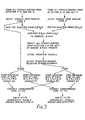
- Figure 3 shows, in flow diagrammatic form, one arrangement by which the data derived from two detectors, arbitrarily designated the r'th and u'th, can be organised to permit the invention to be implemented. This organisation is, of course, duplicated for all overlap zones in a set of paths.
- the electrical and electronic circuits necessary for such implementation can be constructed in hard-wired form or may be constituted by a suitably programmed digital computer or may comprise some form of hybrid circuit arrangement.
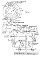
- a CT scanning machine is shown diagrammatically, and it includes an apertured turntable member 14 that can be rotated by conventional means (not shown) around a stationary, apertured support member 16, the relative motion between the two members 14 and 16 being permitted by a large, annular bearing 15 of conventional kind.
- a patient position 17 is defined within the aperture of the support member 16, and the rotation of member 14 takes place about an axis 18.
- a patient to be examined is disposed with a selected cross-sectional slice of his body within the patient position; the axis 18 running longitudinally of the patient's body.
- the turntable member 14 carries an X-ray tube 19 which generates a substantially planar, fan-shaped distribution of X-radiation which is projected across the patient position, traversing the aforementioned body slice, to be collected by an array 24 of collimated X-ray detectors.
- the X-ray tube has an elongated anode 20 and means such as deflection coils 23 for repetitively deflecting the electron beam 22, generated by a cathode assembly 21, to and fro along the anode at a rate substantially higher than the the rate of rotation of the turntable member 14 about the axis 18.
- This expedient repeatedly changes the position of the source location, i.e. the region of impingement of the electron beam on the anode, with respect to the detector array, providing benefits which are known and reported, for example in the published British Patent Application referenced above.
- Figure 4 shows only the "glitch" compensating circuits for two detectors, namely the r'th and u'th detectors, of the array 24. It will be appreciated, however, that similar circuits may be provided for each pair of detectors which provide output signals relating to common overlap zones such as 6.
- the two detectors feed respective pre-processing circuits 25r and 25u wherein, as is conventional in computerised tomography, the electrical output signals provided by the detectors are amplified, integrated digitised and converted to logarithms.
- the integration is carried out under the influence of timing pulses generated as a result of the movement of the turntable member 14 around the axis 18 and occurs at regular, brief intervals so that the detector output signals are sampled rapidly and regularly to produce signals relating to the amounts of radiation transmitted across the body slice along many individual, substantially linear beam paths in the sub-sets 4 and 5 respectively.
- the signals from pre-processors 25r and 25u are applied to a digital store 26, which can take any convenient form.
- Address circuits 27 of known kind are arranged to cause the signals derived from the r'th detector, and relating to the overlap zone 6, to be applied in sequence to a summing circuit 28 where they are combined to produce a signal that can conveniently be disignated Z6r.
- the signals derived from the u'th detector, and relating to the overlap zone 6, are applied in sequence to a summing circuit 29, where they are combined to generate a corresponding signal Z6u.
- the two combined signals, generated by the circuits 28 and 29, are applied to a subtracting circuit 30 wherein the signal ⁇ Z6u is subtracted from the signal ⁇ Z 6 r to produce a signal that can conveniently be designated ⁇ MOD.
- This latter signal MOD is added, in a summing circuit 31, to each individual signal, U5, derived from the detector u, in the sub-set 5.
- This generates modified signals designated U'5 that are stored in a digital store 32.
- those modified signals which relate to the overlap zone 6 are applied to a further digital store 34 whence, under the influence of address circuits 35, they can be applied to respective summing circuits 36 and 37.
- the summing circuit 36 first receives, from store 34, the modified signals corresponding to the signals A', B' and C' in Figure 2, i.e. the first three signals derived from the u'th detector in the overlap zone 6, sums them and applies the resultant sum (X') to a subtracting circuit 38. While this has been going on, the signals r6 derived from the r'th detector in relation to the overlap zone 6 have been stored in a digital store 3 q and, under the influence of address circuits 40, the signals corresponding to A, B and C in Figure 2 have been derived from the store 39 and combined in a summing circuit 41.
- This sum (X) is applied to the subtracting circuit 38 and the arrangement is such that the subtracting circuit 38 forms the difference X-Y'; this difference being applied to a summing circuit 44 for combination therein with the signal B' derived from the store 34 under the influence of the address circuits 35.
- the arrangement is such that the summing circuit 36 generates, in sequence, the following sums:- while the summing circuit 41 generates, in sequence, the following sums:-
- the timing of the operations is such that the sums (a) and (f) are generated simultaneously and are applied to the subtracting circuit 38 which forms the difference (f) - (a) and that difference is supplied to the summing circuit 44 for addition to the signal C'.
- the differences (g) - (b), (h) - (c), (i) - (d) and (j) - (e) are formed sequentially and are added respectively to the signals D', E', F' and G' in circuit 44.
- the summing circuit 37 is arranged to form in sequence, the sums:-
- a similar summing circuit 42 connected to the digital store 39, is arranged to form the following sums:-
- the timing of the operation is such that the sums (aa) and (gg) are generated simultaneously. These sums are applied to a subtracting circuit 43, which forms the difference (aa) - (gg); that difference being added to the signal H' in a summing circuit 45. Likewise, the differences (bb) - (hh), (cc) - (ii), (dd) - (jj), (ee) - (kk) and (ff) - (11) are generated in circuit 43 and added, in circuit 45, to the signals I', J', K', L' and M' respectively.
- the signals provided by the summing circuits 44 and 45, together with the signals produced by all the other similar circuits, are applied to back-projective CT processiong circuits 46 which may, for example, take the form described in British Patent Specification No. 1,471,531.
- circuits 36-38 and 41-43 together with the associated digital stores and addressing circuits, is to generate in sequence individual sums of the first three, five, seven, nine, eleven and thirteen and the last thirteen, eleven, nine, seven, five and three " respectively of the signals produced by both the r'th and u'th detectors and relating to the overlaps zone 6 and to subtract corresponding sums derived from the two detectors. These sums are then added to the appropriate and respective ones of signals B' to M' in order to reduce the effects of afterglow on the comparison between the signals produced by different detectors (the r'th and u'th) in respect of a common overlap zone such as 6.
- the invention relates to CT scanners in which zones of overlap occur between sub-sets of beam paths viewed by different detectors.
- Each overlap zone is used to normalize the output signals derived from the two relevant detectors, but the normalization would be only partially successful, and could result in the occurrence of glitches, in the absence of the invention.
- the output signals obtained in relation to individual beam paths in the overlap zone are utilised to overcome, or at least reduce, the occurrence of glitches.
- Signals obtained from the two detectors in relation to a few beam paths at or adjacent the edges of the overlap zone are used to normalise the individual detector outputs for beam paths near the zone edges whereas signals relating to substantially all of the beam paths in the overlap zone are used to normalise individual detector outputs for beam paths at and adjacent the centre of the overlap zone.
Abstract
Description
- The present invention relates to radiography, and it relates in particular to a branch of radiography which has become known as computerised tomography (CT).
- CT scanners are now an accepted diagnostic tool and they operate by acquiring data relating to the attenuation suffered by penetrative X-radiation on traversing many substantially linear beam paths across a cross-sectional slice of a patient's body, and then processing the data so acquired to produce a representation of the variation of X-ray attenuation or transmission from place to place over the slice.
- British Patent No. 1,283,915 discloses a number of techniques for acquiring the desired data as well as a suitable processing technique.
- Published British Patent Application No. 2,002,988 describes and claims a CT scanner which is capable of rapid data acquisition and which can produce representations which retain, at least to a substantial extent, the remarkable soft tissue differentiating ability of slower scanners. This new CT scanner is one of a rotate-rotate kind (i.e. the radiation source and an associated array of detectors both execute rotational scanning movements around an axis intersecting substantially normally the body slice under examination). The source of radiation includes an extended radiation-emissive target and means for repetitively deflecting an electron beam to and fro along the anode so as to shift the origin of the radiation accordingly. The relationship between the rotational scanning movements and the repetitive deflection of the electron beam is controlled so that data are acquired in respect of many sets of divergent beam paths disposed at different mean angles in the slice, each set being effectively focussed on, or apparently terminating at, a respective "pivot" point disposed outside the locus followed by the source and detector as they rotate.
- Each set is made up of overlapping sub-sets of paths viewed by different detectors, and the paths in the overlap are used, inter alia, for the purpose of evaluating and/or correcting for inter-detector performance differences.
- It is usual for the data relating to an overlap zone and derived from one detector to be averaged and compared with the average of the data relating to the same overlap zone and derived from another detector, thereby to normalise the performances of the two detectors. If this is done, however, problems can arise in the event that one detector has received substantially more radiation than the other just prior to its production of data in relation to the overlap zone. This can happen, for example, when an overlap zone occurs adjacent the edge of the body, a bone edge or a substantial volume of air in a patient's lung. The difficulty arises primarily because of the well known phenomenon, in radiation detectors, which is known as "lag". The detector which has been exposed to the greater amount of radiation produces, in relation to the overlap zone, output signals which are contaminated by residual components left over from its prior exposure to the radiation and thus the output signals obtained, in relation to the same zone, from the two detectors, are not compatible. This causes an apparent sharp discontinuity, or so-called "glitch", to occur in the output signals as processed, and can result in the production of artefacts on the finally produced'representation.
- It is an object of this invention to reduce or eliminate the difficulty referred to above.
- According to the invention there is provided a CT scanner having first and second detector devices for producing data indicative of the attenuation suffered by penetrating radiation on traversing respective sub-sets of substantially linear beam paths traversing a cross-sectional slice of a patient's body, said sub-sets overlapping in an overlap zone, means for .comparing the average values of the data derived from the overlap zone by the said first and second detector devices and for utilising the result of said comparison to normalise the data provided by the two detectors in relation to the entire sub-sets, and means for operating upon the individual data signals to substantially align the data derived from the two detector devices in relation to the overlap zone, said means for operating including, for beam paths at and adjacent the edge of said zone, means for averaging relatively few output signals from both detectors, comparing the averaged values and normalising the output signals on the basis of said comparison and, for beam paths at and adjacent the centre of the overlap zone, means for averaging substantially all of the signals derived from the overlap zone by the two detector devices, for comparing the averaged signals and effecting normalisation on the basis of the comparison.
- In order that the invention may be clearly understood and readily carried into effect, one embodiment thereof will now be described, by way of example only, with reference to the accompanying drawings, of which:-
- Figures 1(a) and 1(b) show, schematically, how the aforementioned "glitch" can arise,
- Figure 2 shows, on enlarged scale, the detector output signals of Figure 1 and is used to assist in explaining how they can be processed, in accordance with one example of the invention, to reduce glitches,
- Figure 3 shows a flow diagram of an arrangement for effecting the processing referred to in relation to Figure. 2, and
- Figure It shows, in block diagrammatic form,a circuit arrangement for effecting the processing referred to in relation to Figure 2, as well as showing, in schematic form, the elements of a CT scanner.
- The disclosure (including the drawings) of published British Patent Application No. 2,002,988 is incorporated herein by reference, and it is therefore deemed unnecessary to repeat herein any more of the information contained in that application.
- Referring now to Figure 1, an edge of a body 1 under examination by a CT scanner is shown at 2. As has been previously mentioned, a set of divergent beam paths, distributed across the body 1 and focussed upon a common "pivot" point 3 is made up of several overlapping sub-sets, such as 4 and 5, of beam paths viewed by different detectors with an overlap zone such as 6, for each neighbouring pair of sub-sets, in respect of which data are provided by both detectors. In circumstances such as those shown in Figure 1, the detector which views the paths of
subset 4 has been exposed to unattenuated radiation. which has passed theedge 2 of the body 1 whereas the detector which views the paths ofsub-set 5 has only been exposed to radiation that has been attenuated by the body. - The output signals derived from the first-mentioned detector, therefore, are contaminated by after-glow to a much greater extent than are the output signals derived from the second-mentioned detector. The variation with position across the subset of the output signals (after pre-processing including logarithmic conversion) derived from the two detectors for
subsets curves 7 and 8 are shown inverted from the disposition that they would usually adopt in practice. The means of the output signals derived from both detectors and relating tozone 6 of overlap are formed independently and then subtracted from one another, the difference being added to all of the output signals in line 8. This raises the readings, as shown in dotted line at 9, to intersect theline 7 at a.point 10 which is considered, in this example, to coincide with the half-way point of the overlap zone. - It will be appreciated that the complete set of output signals for beam paths converging upon point 3 consists of signals for many sub-sets of paths distributed across the body, the signals for each sub-set being derived from a respective detector and adjacent sub-sets overlapping to produce overlap zones, like
zone 6, distributed regularly in angle across the body 1. Each overlap zone can be used to normalise the performances of the two detectors concerned as just described in relation to Figure 1(b). - It is conventional to use, for processing, the output signals disposed on
line 7 as far as thepoint 10, then the signals disposed on line 9 (i.e. the "corrected" or normalised signals corresponding to line 8) as far as apoint 11 which corresponds to the centre of the overlap zone betweensub-set 5 and the next adjacent sub-set (not shown) towards the centre of the body 1. Frompoint 11, the signals used are those corresponding to the corrected (normalised) signals for the detector viewing the paths of the said next adjacent sub-set, and so on. In this way a chain of normalised signals extending across the body is constructed for the paths converging on pivot point 3. It will be appreciated that the same procedure is carried out in respect of paths converging on all of the other pivot points distributed (as described in published British Patent Application No. 2,002,988) around the body 1. - The above technique, however, suffers from the problem that output signals such as those disposed between
points 10 and 12 (the latter being the end of the line) online 7, between points 13 (the start of corrected line 9) and 10, and corresponding signals relating to other sub-sets are not specifically used, other than in the averaging process. If such signals were merely 'meaned' with corresponding values of used signals, glitches would result. However such signals must be used in order to optimise the usage of radiation dose administered to the patient. - Figure 2 shows how the above problem can be overcome in accordance with one example of the invention, and it shows on expanded scale the
lines point 10, the centre of the overlap zone. It will be appreciated that output signals relating to several beam paths (in this example fourteen beam paths) are derived from each detector in each of the overlap zones such as 6. - In order to use substantially all output signals and yet avoid the production of glitches, the output signals which would otherwise not be specifically used (e.g. those in the regions 13-10 of
line 9 and 10-12 of line 7), the invention introduces low frequency corrections and one example of how this can be done will now be described. - It will be appreciated that the object of the invention is to effectively bend the region 13-10 of
line 9 until it substantially coincides withline 7 and to bend the region 10-12 ofline 7 until it substantially coincides withline 9. - In accordance with one example of the invention, the procedure is as follows:-
- 1. A mean is taken of signals A, B and C on
line 7. - 2. A mean is taken of signals A', B' and C' on
line 9. - 3. The difference is added to signal B' and this will cause it to substantially equal the signal B.
- For signal C', the procedure is the same as that described above, except that means of signals A to E and A' to E' are differenced and added to C'. For signal D' the means of signals A-G and A'-G' are used; for signal E' the means of signals A-G, H' and I' and A'-G', H and I are used, and so-on in accordance with the following table:-
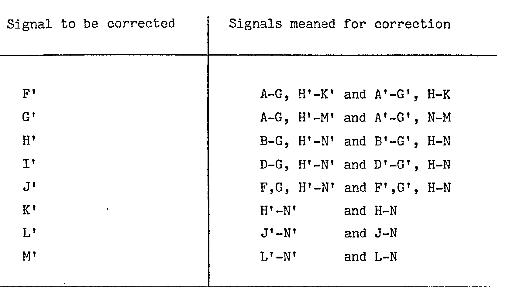
- It will be appreciated that readings A' and N' could use the same corrections as B' and M'. On the other hand, they need not be used as these readings represent only about 7% of the data acquired from the overlap zones and, as such, their non-utilisation is acceptable.
- It will be appreciated that the only information added to the "end" signals B'and M'consists of relatively high frequency variations as between adjacent pixels. As the signals approach the
point 10, the frequency range of the variations is extended downwards. - The end result of the application of the invention is to substantially, though not completely, equalise signals B and B', C and C', D and D' etc. and these corresponding signals are "meaned" and used for processing. In some circumstances, the overlap zones are not contiguous, so that beam paths in certain zones, between the overlap zones, are viewed by one detector only. If this occurs, the output signals relating to such beam paths can be doubled, prior to processing, to render them compatible with the summed signals derived from the overlap zones.
- Figure 3 shows, in flow diagrammatic form, one arrangement by which the data derived from two detectors, arbitrarily designated the r'th and u'th, can be organised to permit the invention to be implemented. This organisation is, of course, duplicated for all overlap zones in a set of paths. The electrical and electronic circuits necessary for such implementation can be constructed in hard-wired form or may be constituted by a suitably programmed digital computer or may comprise some form of hybrid circuit arrangement.
- It is convenient to consider the flow diagram of Figure 3 in conjunction with the circuit diagram of
circuit 4. In Figure 4, a CT scanning machine is shown diagrammatically, and it includes anapertured turntable member 14 that can be rotated by conventional means (not shown) around a stationary, apertured support member 16, the relative motion between the twomembers 14 and 16 being permitted by a large, annular bearing 15 of conventional kind. A patient position 17 is defined within the aperture of the support member 16, and the rotation ofmember 14 takes place about anaxis 18. In operation, a patient to be examined is disposed with a selected cross-sectional slice of his body within the patient position; theaxis 18 running longitudinally of the patient's body. - The
turntable member 14 carries anX-ray tube 19 which generates a substantially planar, fan-shaped distribution of X-radiation which is projected across the patient position, traversing the aforementioned body slice, to be collected by anarray 24 of collimated X-ray detectors. In this example, the X-ray tube has an elongatedanode 20 and means such as deflection coils 23 for repetitively deflecting theelectron beam 22, generated by acathode assembly 21, to and fro along the anode at a rate substantially higher than the the rate of rotation of theturntable member 14 about theaxis 18. This expedient repeatedly changes the position of the source location, i.e. the region of impingement of the electron beam on the anode, with respect to the detector array, providing benefits which are known and reported, for example in the published British Patent Application referenced above. - In order to assist in the clear understanding of this invention, Figure 4 shows only the "glitch" compensating circuits for two detectors, namely the r'th and u'th detectors, of the
array 24. It will be appreciated, however, that similar circuits may be provided for each pair of detectors which provide output signals relating to common overlap zones such as 6. Referring again to the drawing, the two detectors feedrespective pre-processing circuits 25r and 25u wherein, as is conventional in computerised tomography, the electrical output signals provided by the detectors are amplified, integrated digitised and converted to logarithms. The integration is carried out under the influence of timing pulses generated as a result of the movement of theturntable member 14 around theaxis 18 and occurs at regular, brief intervals so that the detector output signals are sampled rapidly and regularly to produce signals relating to the amounts of radiation transmitted across the body slice along many individual, substantially linear beam paths in thesub-sets - The signals from
pre-processors 25r and 25u are applied to adigital store 26, which can take any convenient form.Address circuits 27 of known kind are arranged to cause the signals derived from the r'th detector, and relating to theoverlap zone 6, to be applied in sequence to a summingcircuit 28 where they are combined to produce a signal that can conveniently be disignated Z6r. Likewise, and again under the influence of theaddress circuits 27, the signals derived from the u'th detector, and relating to theoverlap zone 6, are applied in sequence to a summingcircuit 29, where they are combined to generate a corresponding signal Z6u. The two combined signals, generated by thecircuits circuit 30 wherein the signal ΣZ6u is subtracted from the signal ΣZ6r to produce a signal that can conveniently be designated ΣMOD. This latter signal MOD is added, in a summingcircuit 31, to each individual signal, U5, derived from the detector u, in thesub-set 5. This generates modified signals designated U'5 that are stored in adigital store 32. Under the influence ofaddress circuits 33, those modified signals which relate to theoverlap zone 6 are applied to a furtherdigital store 34 whence, under the influence ofaddress circuits 35, they can be applied to respective summingcircuits - The summing
circuit 36 first receives, fromstore 34, the modified signals corresponding to the signals A', B' and C' in Figure 2, i.e. the first three signals derived from the u'th detector in theoverlap zone 6, sums them and applies the resultant sum (X') to a subtractingcircuit 38. While this has been going on, the signals r6 derived from the r'th detector in relation to theoverlap zone 6 have been stored in a digital store 3q and, under the influence ofaddress circuits 40, the signals corresponding to A, B and C in Figure 2 have been derived from thestore 39 and combined in a summingcircuit 41. This sum (X) is applied to the subtractingcircuit 38 and the arrangement is such that the subtractingcircuit 38 forms the difference X-Y'; this difference being applied to a summingcircuit 44 for combination therein with the signal B' derived from thestore 34 under the influence of theaddress circuits 35. - The arrangement is such that the summing
circuit 36 generates, in sequence, the following sums:-while the summing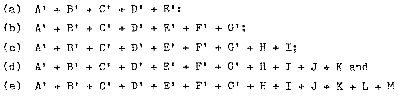
circuit 41 generates, in sequence, the following sums:-
- The timing of the operations is such that the sums (a) and (f) are generated simultaneously and are applied to the subtracting
circuit 38 which forms the difference (f) - (a) and that difference is supplied to the summingcircuit 44 for addition to the signal C'. Likewise, the differences (g) - (b), (h) - (c), (i) - (d) and (j) - (e) are formed sequentially and are added respectively to the signals D', E', F' and G' incircuit 44. - In a similar manner, the signals for combination with the signals H' to N' are generated
- The summing
circuit 37 is arranged to form in sequence, the sums:-
- A similar summing
circuit 42, connected to thedigital store 39, is arranged to form the following sums:-
- The timing of the operation is such that the sums (aa) and (gg) are generated simultaneously. These sums are applied to a subtracting
circuit 43, which forms the difference (aa) - (gg); that difference being added to the signal H' in a summingcircuit 45. Likewise, the differences (bb) - (hh), (cc) - (ii), (dd) - (jj), (ee) - (kk) and (ff) - (11) are generated incircuit 43 and added, incircuit 45, to the signals I', J', K', L' and M' respectively. - The signals provided by the summing
circuits CT processiong circuits 46 which may, for example, take the form described in British Patent Specification No. 1,471,531. - It will be appreciated that the action of the circuits 36-38 and 41-43, together with the associated digital stores and addressing circuits, is to generate in sequence individual sums of the first three, five, seven, nine, eleven and thirteen and the last thirteen, eleven, nine, seven, five and three " respectively of the signals produced by both the r'th and u'th detectors and relating to the
overlaps zone 6 and to subtract corresponding sums derived from the two detectors. These sums are then added to the appropriate and respective ones of signals B' to M' in order to reduce the effects of afterglow on the comparison between the signals produced by different detectors (the r'th and u'th) in respect of a common overlap zone such as 6. - It will be appreciated that the operation of many of the circuits shown in Figure 4, and in particular the digital stores and their associated addressing circuits is, in known manner, controlled by a master timing circuit (not shown).
- In summary, then, it will be appreciated that the invention relates to CT scanners in which zones of overlap occur between sub-sets of beam paths viewed by different detectors. Each overlap zone is used to normalize the output signals derived from the two relevant detectors, but the normalization would be only partially successful, and could result in the occurrence of glitches, in the absence of the invention. In accordance with the invention, the output signals obtained in relation to individual beam paths in the overlap zone are utilised to overcome, or at least reduce, the occurrence of glitches. Signals obtained from the two detectors in relation to a few beam paths at or adjacent the edges of the overlap zone are used to normalise the individual detector outputs for beam paths near the zone edges whereas signals relating to substantially all of the beam paths in the overlap zone are used to normalise individual detector outputs for beam paths at and adjacent the centre of the overlap zone.
Claims (4)
Applications Claiming Priority (2)
| Application Number | Priority Date | Filing Date | Title |
|---|---|---|---|
| GB7841710 | 1978-10-24 | ||
| GB4171078 | 1978-10-24 |
Publications (2)
| Publication Number | Publication Date |
|---|---|
| EP0010885A1 true EP0010885A1 (en) | 1980-05-14 |
| EP0010885B1 EP0010885B1 (en) | 1983-02-23 |
Family
ID=10500545
Family Applications (1)
| Application Number | Title | Priority Date | Filing Date |
|---|---|---|---|
| EP79302180A Expired EP0010885B1 (en) | 1978-10-24 | 1979-10-11 | Computerized tomographic apparatus |
Country Status (5)
| Country | Link |
|---|---|
| US (1) | US4295195A (en) |
| EP (1) | EP0010885B1 (en) |
| JP (1) | JPS5560444A (en) |
| CA (1) | CA1127776A (en) |
| DE (1) | DE2964915D1 (en) |
Cited By (1)
| Publication number | Priority date | Publication date | Assignee | Title |
|---|---|---|---|---|
| EP0124015A2 (en) * | 1983-05-02 | 1984-11-07 | General Electric Company | Method and apparatus for reducing image artifacts due to projection measurement inconsistencies |
Families Citing this family (17)
| Publication number | Priority date | Publication date | Assignee | Title |
|---|---|---|---|---|
| FR2519445B1 (en) * | 1981-12-31 | 1985-12-27 | Thomson Csf | DYNAMIC MODE TOMODENSITOMETRIC IMAGING METHOD, AND TOMODENSITOMETER USING SUCH A METHOD |
| HU188196B (en) * | 1982-08-19 | 1986-03-28 | Medicor Muevek,Hu | Firmware back-projector for ct systems |
| JPS59148854A (en) * | 1983-02-14 | 1984-08-25 | Hitachi Ltd | Testing apparatus using nuclear magnetic resonance |
| US4670840A (en) * | 1983-03-09 | 1987-06-02 | Elscint, Inc. | Ring artifact correction for computerized tomography |
| IL70978A (en) * | 1983-03-09 | 1987-03-31 | Elscint Ltd | Methods for improving ct scanner images |
| JPS60168436A (en) * | 1984-02-10 | 1985-08-31 | 横河メディカルシステム株式会社 | Calculator tomography apparatus |
| US4752879A (en) * | 1985-01-30 | 1988-06-21 | Picker International, Inc. | Method and apparatus for medical imaging |
| US4686692A (en) * | 1985-04-12 | 1987-08-11 | Picker International Inc. | Computed tomography patient localization scanning |
| US4751644A (en) * | 1985-10-28 | 1988-06-14 | Picker International, Inc. | Interleaved source fan reconstruction technique |
| IL98945A0 (en) * | 1991-07-24 | 1992-07-15 | Elscint Ltd | Multiple slice ct scanner |
| US5241576A (en) * | 1991-12-23 | 1993-08-31 | General Electric Company | Segmented detector containing sub-elements for separate measuring of a fan beam |
| JP3587435B2 (en) | 1998-10-16 | 2004-11-10 | 株式会社タカラ | Display panel |
| DE10016372B4 (en) * | 1999-10-14 | 2004-04-29 | Centrum für Dentale Innovationen GmbH | Layering method and layering device |
| JP3656732B2 (en) | 2000-04-21 | 2005-06-08 | 日産自動車株式会社 | Energy conversion fiber and sound absorbing material |
| US6657354B2 (en) | 2000-12-06 | 2003-12-02 | Asmo Co., Ltd. | Dynamo-electric machine having commutator and manufacturing method thereof |
| JP2003089313A (en) | 2001-09-18 | 2003-03-25 | Denso Corp | Air conditioner for vehicle |
| US6725708B2 (en) | 2002-09-13 | 2004-04-27 | Akashi Corporation | Impression forming mechanism and method, and hardness testing apparatus and method |
Citations (4)
| Publication number | Priority date | Publication date | Assignee | Title |
|---|---|---|---|---|
| GB1471531A (en) * | 1973-04-25 | 1977-04-27 | Emi Ltd | Radiography |
| GB1497396A (en) * | 1974-03-23 | 1978-01-12 | Emi Ltd | Radiography |
| DE2648132A1 (en) * | 1976-10-23 | 1978-04-27 | Philips Patentverwaltung | PROCEDURE AND ARRANGEMENT TO REDUCE THE INFLUENCE OF DETECTOR FAULTS IN ROENTGEN SCANNERS |
| GB2002988A (en) * | 1977-08-18 | 1979-02-28 | Emi Ltd | Radiography |
Family Cites Families (3)
| Publication number | Priority date | Publication date | Assignee | Title |
|---|---|---|---|---|
| US4032761A (en) * | 1974-10-11 | 1977-06-28 | E M I Limited | Tomography |
| GB1530621A (en) * | 1975-02-08 | 1978-11-01 | Emi Ltd | Radiography |
| US4105922A (en) * | 1977-04-11 | 1978-08-08 | General Electric Company | CT number identifier in a computed tomography system |
-
1979
- 1979-10-11 EP EP79302180A patent/EP0010885B1/en not_active Expired
- 1979-10-11 DE DE7979302180T patent/DE2964915D1/en not_active Expired
- 1979-10-17 CA CA337,763A patent/CA1127776A/en not_active Expired
- 1979-10-24 JP JP13753379A patent/JPS5560444A/en active Granted
- 1979-10-24 US US06/087,669 patent/US4295195A/en not_active Expired - Lifetime
Patent Citations (4)
| Publication number | Priority date | Publication date | Assignee | Title |
|---|---|---|---|---|
| GB1471531A (en) * | 1973-04-25 | 1977-04-27 | Emi Ltd | Radiography |
| GB1497396A (en) * | 1974-03-23 | 1978-01-12 | Emi Ltd | Radiography |
| DE2648132A1 (en) * | 1976-10-23 | 1978-04-27 | Philips Patentverwaltung | PROCEDURE AND ARRANGEMENT TO REDUCE THE INFLUENCE OF DETECTOR FAULTS IN ROENTGEN SCANNERS |
| GB2002988A (en) * | 1977-08-18 | 1979-02-28 | Emi Ltd | Radiography |
Cited By (2)
| Publication number | Priority date | Publication date | Assignee | Title |
|---|---|---|---|---|
| EP0124015A2 (en) * | 1983-05-02 | 1984-11-07 | General Electric Company | Method and apparatus for reducing image artifacts due to projection measurement inconsistencies |
| EP0124015A3 (en) * | 1983-05-02 | 1987-05-13 | General Electric Company | Method for reducing image artifacts due to projection measurement inconsistencies |
Also Published As
| Publication number | Publication date |
|---|---|
| EP0010885B1 (en) | 1983-02-23 |
| JPH0257B2 (en) | 1990-01-05 |
| JPS5560444A (en) | 1980-05-07 |
| US4295195A (en) | 1981-10-13 |
| CA1127776A (en) | 1982-07-13 |
| DE2964915D1 (en) | 1983-03-31 |
Similar Documents
| Publication | Publication Date | Title |
|---|---|---|
| US4295195A (en) | Radiography | |
| US5864598A (en) | Methods and apparatus for scanning an object in a computed tomography system | |
| US6421411B1 (en) | Methods and apparatus for helical image artifact reduction | |
| EP1374776B1 (en) | Methods and apparatus for operating a radiation source | |
| US5128864A (en) | Method for computing tomographic scans | |
| US7409043B2 (en) | Method and apparatus to control radiation tube focal spot size | |
| US5606585A (en) | Methods and apparatus for multislice helical image reconstruction in a computer tomography system | |
| US5400379A (en) | Multi-slice x-ray CT using a detector mask | |
| JPH10272131A (en) | Method and apparatus for correcting slice thickness of imaging apparatus | |
| GB2035748A (en) | Radiography | |
| US6047039A (en) | Method for post-processing of a tomogram, and computed tomography apparatus operating in accordance with the method | |
| US6381297B1 (en) | High pitch reconstruction of multislice CT scans | |
| US5974110A (en) | Helical reconstruction algorithm | |
| US5561695A (en) | Methods and apparatus for reducing image artifacts | |
| US6343110B1 (en) | Methods and apparatus for submillimeter CT slices with increased coverage | |
| US6061423A (en) | Fluoroscopy image reconstruction | |
| EP0353299B1 (en) | Convolution processing method for x-ray tomographic equipment | |
| US6600802B1 (en) | Image space correction for multi-slice helical reconstruction with z-smoothing | |
| US6798860B1 (en) | Methods and apparatus for deconvolving imaging data | |
| US6597756B1 (en) | Methods and apparatus for multi-slice image reconstruction | |
| US6278762B1 (en) | Systems, methods and apparatus for reconstructing images | |
| US6366637B1 (en) | Methods and apparatus for generating thin-slice imaging data on a multi-slice imaging system | |
| US6185275B1 (en) | Systems and methods for correcting focal spot thermal drift | |
| DE2822241A1 (en) | SCANNING X-RAY EXAM ARRANGEMENT | |
| US20200015769A1 (en) | X-ray computed tomography apparatus and correction method |
Legal Events
| Date | Code | Title | Description |
|---|---|---|---|
| PUAI | Public reference made under article 153(3) epc to a published international application that has entered the european phase |
Free format text: ORIGINAL CODE: 0009012 |
|
| AK | Designated contracting states |
Designated state(s): BE DE FR GB NL SE |
|
| 17P | Request for examination filed | ||
| GRAA | (expected) grant |
Free format text: ORIGINAL CODE: 0009210 |
|
| STAA | Information on the status of an ep patent application or granted ep patent |
Free format text: STATUS: THE PATENT HAS BEEN GRANTED |
|
| AK | Designated contracting states |
Designated state(s): BE DE FR GB NL SE |
|
| REF | Corresponds to: |
Ref document number: 2964915 Country of ref document: DE Date of ref document: 19830331 |
|
| ET | Fr: translation filed | ||
| REG | Reference to a national code |
Ref country code: GB Ref legal event code: 732 |
|
| REG | Reference to a national code |
Ref country code: FR Ref legal event code: TP |
|
| PGFP | Annual fee paid to national office [announced via postgrant information from national office to epo] |
Ref country code: SE Payment date: 19930721 Year of fee payment: 15 |
|
| PGFP | Annual fee paid to national office [announced via postgrant information from national office to epo] |
Ref country code: FR Payment date: 19930802 Year of fee payment: 15 |
|
| PGFP | Annual fee paid to national office [announced via postgrant information from national office to epo] |
Ref country code: GB Payment date: 19930804 Year of fee payment: 15 |
|
| PGFP | Annual fee paid to national office [announced via postgrant information from national office to epo] |
Ref country code: BE Payment date: 19931013 Year of fee payment: 15 |
|
| PGFP | Annual fee paid to national office [announced via postgrant information from national office to epo] |
Ref country code: NL Payment date: 19931031 Year of fee payment: 15 |
|
| PGFP | Annual fee paid to national office [announced via postgrant information from national office to epo] |
Ref country code: DE Payment date: 19931229 Year of fee payment: 15 |
|
| NLS | Nl: assignments of ep-patents |
Owner name: THORN EMI PATENTS LIMITED TE HAYES, GROOT-BRITTANN |
|
| PG25 | Lapsed in a contracting state [announced via postgrant information from national office to epo] |
Ref country code: GB Effective date: 19941011 |
|
| PG25 | Lapsed in a contracting state [announced via postgrant information from national office to epo] |
Ref country code: SE Effective date: 19941012 |
|
| PG25 | Lapsed in a contracting state [announced via postgrant information from national office to epo] |
Ref country code: BE Effective date: 19941031 |
|
| EAL | Se: european patent in force in sweden |
Ref document number: 79302180.9 |
|
| BERE | Be: lapsed |
Owner name: THORN EMI PATENT LTD Effective date: 19941031 |
|
| PG25 | Lapsed in a contracting state [announced via postgrant information from national office to epo] |
Ref country code: NL Effective date: 19950501 |
|
| GBPC | Gb: european patent ceased through non-payment of renewal fee |
Effective date: 19941011 |
|
| NLV4 | Nl: lapsed or anulled due to non-payment of the annual fee | ||
| PG25 | Lapsed in a contracting state [announced via postgrant information from national office to epo] |
Ref country code: FR Effective date: 19950630 |
|
| PG25 | Lapsed in a contracting state [announced via postgrant information from national office to epo] |
Ref country code: DE Effective date: 19950701 |
|
| EUG | Se: european patent has lapsed |
Ref document number: 79302180.9 |
|
| REG | Reference to a national code |
Ref country code: FR Ref legal event code: ST |
|
| PLBE | No opposition filed within time limit |
Free format text: ORIGINAL CODE: 0009261 |