EP0010940A1 - Apparatus for measuring the colour of a product - Google Patents
Apparatus for measuring the colour of a product Download PDFInfo
- Publication number
- EP0010940A1 EP0010940A1 EP79302357A EP79302357A EP0010940A1 EP 0010940 A1 EP0010940 A1 EP 0010940A1 EP 79302357 A EP79302357 A EP 79302357A EP 79302357 A EP79302357 A EP 79302357A EP 0010940 A1 EP0010940 A1 EP 0010940A1
- Authority
- EP
- European Patent Office
- Prior art keywords
- colour
- signal
- product
- target
- light
- Prior art date
- Legal status (The legal status is an assumption and is not a legal conclusion. Google has not performed a legal analysis and makes no representation as to the accuracy of the status listed.)
- Ceased
Links
- 238000000034 method Methods 0.000 claims abstract description 15
- 239000003607 modifier Substances 0.000 claims description 19
- 238000012544 monitoring process Methods 0.000 claims description 3
- 235000013305 food Nutrition 0.000 abstract description 4
- 235000013399 edible fruits Nutrition 0.000 abstract 1
- 235000013311 vegetables Nutrition 0.000 abstract 1
- 239000004020 conductor Substances 0.000 description 8
- 238000004886 process control Methods 0.000 description 8
- 238000010411 cooking Methods 0.000 description 7
- 230000000694 effects Effects 0.000 description 5
- 230000001105 regulatory effect Effects 0.000 description 5
- 238000010586 diagram Methods 0.000 description 3
- 238000012545 processing Methods 0.000 description 3
- 244000061456 Solanum tuberosum Species 0.000 description 2
- 235000002595 Solanum tuberosum Nutrition 0.000 description 2
- 239000008162 cooking oil Substances 0.000 description 2
- 238000005259 measurement Methods 0.000 description 2
- 239000002184 metal Substances 0.000 description 2
- 229910052751 metal Inorganic materials 0.000 description 2
- 238000009877 rendering Methods 0.000 description 2
- 238000012360 testing method Methods 0.000 description 2
- 244000105624 Arachis hypogaea Species 0.000 description 1
- 206010033546 Pallor Diseases 0.000 description 1
- 230000015572 biosynthetic process Effects 0.000 description 1
- 238000006243 chemical reaction Methods 0.000 description 1
- 230000009849 deactivation Effects 0.000 description 1
- 238000000151 deposition Methods 0.000 description 1
- 230000006866 deterioration Effects 0.000 description 1
- 230000003292 diminished effect Effects 0.000 description 1
- 238000001914 filtration Methods 0.000 description 1
- 235000012055 fruits and vegetables Nutrition 0.000 description 1
- 239000003517 fume Substances 0.000 description 1
- 238000010438 heat treatment Methods 0.000 description 1
- 238000010348 incorporation Methods 0.000 description 1
- 230000007774 longterm Effects 0.000 description 1
- 150000002739 metals Chemical class 0.000 description 1
- 235000020232 peanut Nutrition 0.000 description 1
- 235000013606 potato chips Nutrition 0.000 description 1
- 235000012015 potatoes Nutrition 0.000 description 1
- 230000000717 retained effect Effects 0.000 description 1
- 238000000926 separation method Methods 0.000 description 1
- 239000002699 waste material Substances 0.000 description 1
Images


Classifications
-
- B—PERFORMING OPERATIONS; TRANSPORTING
- B07—SEPARATING SOLIDS FROM SOLIDS; SORTING
- B07C—POSTAL SORTING; SORTING INDIVIDUAL ARTICLES, OR BULK MATERIAL FIT TO BE SORTED PIECE-MEAL, e.g. BY PICKING
- B07C5/00—Sorting according to a characteristic or feature of the articles or material being sorted, e.g. by control effected by devices which detect or measure such characteristic or feature; Sorting by manually actuated devices, e.g. switches
- B07C5/34—Sorting according to other particular properties
- B07C5/342—Sorting according to other particular properties according to optical properties, e.g. colour
-
- G—PHYSICS
- G01—MEASURING; TESTING
- G01J—MEASUREMENT OF INTENSITY, VELOCITY, SPECTRAL CONTENT, POLARISATION, PHASE OR PULSE CHARACTERISTICS OF INFRARED, VISIBLE OR ULTRAVIOLET LIGHT; COLORIMETRY; RADIATION PYROMETRY
- G01J3/00—Spectrometry; Spectrophotometry; Monochromators; Measuring colours
- G01J3/46—Measurement of colour; Colour measuring devices, e.g. colorimeters
- G01J3/50—Measurement of colour; Colour measuring devices, e.g. colorimeters using electric radiation detectors
-
- G—PHYSICS
- G01—MEASURING; TESTING
- G01J—MEASUREMENT OF INTENSITY, VELOCITY, SPECTRAL CONTENT, POLARISATION, PHASE OR PULSE CHARACTERISTICS OF INFRARED, VISIBLE OR ULTRAVIOLET LIGHT; COLORIMETRY; RADIATION PYROMETRY
- G01J3/00—Spectrometry; Spectrophotometry; Monochromators; Measuring colours
- G01J3/46—Measurement of colour; Colour measuring devices, e.g. colorimeters
- G01J3/52—Measurement of colour; Colour measuring devices, e.g. colorimeters using colour charts
- G01J3/524—Calibration of colorimeters
-
- G—PHYSICS
- G01—MEASURING; TESTING
- G01J—MEASUREMENT OF INTENSITY, VELOCITY, SPECTRAL CONTENT, POLARISATION, PHASE OR PULSE CHARACTERISTICS OF INFRARED, VISIBLE OR ULTRAVIOLET LIGHT; COLORIMETRY; RADIATION PYROMETRY
- G01J3/00—Spectrometry; Spectrophotometry; Monochromators; Measuring colours
- G01J3/46—Measurement of colour; Colour measuring devices, e.g. colorimeters
- G01J3/50—Measurement of colour; Colour measuring devices, e.g. colorimeters using electric radiation detectors
- G01J3/51—Measurement of colour; Colour measuring devices, e.g. colorimeters using electric radiation detectors using colour filters
- G01J3/513—Measurement of colour; Colour measuring devices, e.g. colorimeters using electric radiation detectors using colour filters having fixed filter-detector pairs
Definitions
- This invention relates to apparatus for measuring the colour of a product.
- the invention recognizes the need to calibrate such apparatus and provides means and a method to this end.
- Colour grading apparatus is utilized to detect the colour of products, especially food products such as fruit and vegetables or food being processed, for separating those having a colour outside selected limits. Such separation might be used to delete spoiled or blemished products as well as those overripe or underripe.
- colour grading apparatus can be used to control processes wherein a colour change results from the process.
- the cooking temperature of the chips can be regulated by detecting the colour of the chips as they leave the oven.
- the resulting colour-responsive signal can be compared to a reference signal indicating the product colour desired to control the process for cooking the product so that the desired colour is obtained.
- a major problem in such systems results from the tendency of the light-emitting devices to vary the light wavelength emitted with usage, thereby rendering the colour indication erroneous. Such change can result from deterioration of the light source which will change the intensity or the wavelength of the light directed onto the product.
- a more common problem results from the deposit of moisture, cooking oil or other film on the light-emitting head or lens which tends to filter or reduce the intensity of the light. For instance in the monitoring of a cooking process, the product coming out of the oven is surrounded by heated cooking oil and moisture-laden air. Fumes naturally rise around the colour grading apparatus and in a short time can result in the formation of deposits on the light-emitting head. Any such deposits serve to obstruct the passage of light from the head to the product and filter certain light wavelengths to make the subsequent colour reading erroneous in indicating the true colour of the product.
- Colour grading apparatus is described in United States Patents 4,057,352, Color Grading Apparatus Utilizing Infrared Light Source, R. Babb, issued on November 8, 1977; and 3,998,555, Color Grading Apparatus, R. Babb, issued on December 21, 1976.
- the invention provides apparatus for measuring the colour of a product, comprising
- a colour detecting head for detecting light radiating from the product and for generating a colour signal responsive to the colour of the product
- apparatus for measuring the colour of a product comprising
- Apparatus suitable for incorporation of the subject invention is shown as prior art in Figure 1 wherein the product 10 carried by a conveyor belt 11 is tested for colour.
- the conveyor carries the product, usually a food product, from an oven or other form of processing station. It is desired to control this process by testing the colour of the product as it comes out and by readjusting the process so that the colour of the product falls within a predetermined colour range thereby indicating a satisfactory processing has been accomplished.
- the product is tested by exposing it to light of a predetermined frequency range such as that emitted by the light sources 12 and 14 in a colour detecting head.
- These light sources are in a housing 15 positioned directly over the path of the product being measured.
- the light sources are of a cylindrical configuration with a centre opening through which reflected light from the product can pass back into a lens system 17 leading into an enclosed lightproof housing 18.
- the light strikes a dichroic mirror 19 which is used because in this embodiment two different light regions are sensed to detect the properties desired.
- the dichroic mirror passes one predetermined light region and reflects another.
- the light passing through the dichroic reflector strikes a filter 20 and a photodiode 21.
- the reflected light passes through a separate filter 22 and strikes a photodiode 24. In this manner the reflected light is detected in two separate light regions of predetermined frequencies.
- the filtering of the reflected light must be sufficiently efficient to make the light intensities a true indication of the reflected colour of the product.
- the signals resulting from the two light regions detected are subsequently compared for the generation of a ratio signal.
- the ratio signal variables are eliminated which otherwise might affect the reflected light intensities but which have little to do with the colour or processing of the product. For instance if the product quantity on the support or conveyor belt varies, the colour of the conveyor belt can show through the lesser quantity product and change the intensity of reflected light in various frequency ranges.
- the intensity of the reflected light can change.
- the overall intensities of the light sources also may diminish.
- the signals from the photodetectors 21 and 24 are fed through parallel electrical circuits each including amplifiers 25 and 26, integrators 27 and 28, and additional amplifiers 29 and 30, respectively.
- Each signal is processed in the respective circuit and fed to an analogue divider 31 for the generation of the signal responsive to the ratio of the intensities of the reflectance in the two selected frequency ranges.
- the output from the analogue divider is fed to a readout device 32 which in the normal case is a meter or recording strip chart.
- the signal can be fed to a process control 34 for the purpose of regulating the process occurring immediately preceding the colour measurement.
- Such systems can be used in processes wherein the product is to be heated, for instance in the blanching of french-fried potatoes or roasting peanuts wherein the colour changes with the intensity of the heating.
- the process can be regulated to produce a uniformly coloured product.
- colour-sensing apparatus can be applied in potato peelers and the like to test the degree of peeling and control the peeling process so as to minimize waste while rendering an effective peeling operation.
- controls regulated by colour-sensing apparatus are many other uses for such controls regulated by colour-sensing apparatus.
- the process control can be used either to control the heat of a furnace (not shown) or the speed by which the conveyor carries the product 10 for cooking.
- the control can either speed up or slow down the conveyor depending upon whether less or more cooking of the product is desired.
- the time the product spends in the oven can be regulated by use of the process control 34. It is also possible to control the temperature of the oven while leaving the conveyor speed constant to control the degree of cooking. Such controls are well-known.
- a circuit for automatically calibrating the colour apparatus Accordingly as shown in Figure 2 there is incorporated between the readout device 32 and the analogue divider 31 an automatic calibrator 36 which serves to check the calibration of the instrument periodically to allow the generation of a modifying signal to correct inaccuracies in the readout signal of the apparatus.
- the automatic calibrator acts under control of a control calibrator 37. This control energizes an actuator 39 for rotating the target 35 and initiates the calibration sequence.
- the readout signal is then compared to a predetermined signal and a modifying signal is generated responsive to any difference therebetween.
- the signals from the amplifiers 29 and 30 are fed to an analogue divider 31 which in turn supplies the resulting ratio signal to the automatic calibrator 36.
- This colour signal is transmitted through the conductor 41 to an analogue multiplier 42.
- switch 44 is closed thereby allowing the signal to pass through the analogue multiplier, the switch 44, the conductor 45, to a sample and hold 46 from which it is subsequently conducted to the readout device 32 and the process control 34.
- the analogue multiplier 42 modifies the readout signal by a signal Z received through the conductor.47 to adjust the readout signal by an amount determined by the immediately previous calibration sequence. The operation of the calibration sequence will be explained hereinafter.
- the calibration control 37 signals the actuator 39 to move the disc 35 beneath the light detecting head. At the same time a signal is transmitted through the conductor 38 to the automatic calibrator 36 to open the switch 44 and, through the conductor 47, to energize the sample and hold circuit 48.
- the switch 44 is opened so that during calibration, broad excursions of signal strength which might exceed the range of the readout device are not transmitted to the readout device.
- the sample and hold circuit 46 holds the setting at the previously detected level to regulate the process control 34.
- the analogue to digital converter 49 and the digital to analogue converter 50 receive the signal from the analogue divider 31 resulting from the light reading of the disc 35.
- the sample and hold circuit serves to hold that signal level and also to transmit it as a signal Y to an analogue divider 51.
- the analogue divider 51 in the example shown receives a constant voltage signal from a voltage source 52 and performs the function (K (2.5/Y)). This function compares the signal Y to a value K which corresponds to the known signal which should be received from the head in reading the colour of the disc 35. Thereafter the resulting modifying signal Z generated by the analogue divider is fed through the conductor 47 to the analogue multiplier 42.
- the calibration control energizes the actuator 39 to move the disc 35 from beneath the light detecting head 15. At the same time the switch 44 is closed. With the subsequent reading of the colour of a product passing along the conveyor 11, the resulting ratio signal is generated by the analogue divider 31 in the manner previously described and transmitted through the conductors 40 and 41 to the analogue multiplier 42.
- the sample and hold circuit in retaining the previous signal resulting from the reading of the disc 35, transmits the signal Y to the analogue divider which in turn generates the modifying signal Z received by the analogue multiplier.
- the analogue multiplier modifies the incoming ratio signal with the resulting modified signal being transmitted through the switch 44, the sample and hold circuit 46 to the readout device 32 and the process control 34.
- the calibrating sequence serves to generate a modifying signal which is retained and used for correcting all subsequent ratio signals generated by the colour apparatus. Whether or not the signal received from the colour apparatus is a result of a direct reading of a colour or the result of the generation of a ratio as described herein, the automatic calibrator serves to adjust such signals for greater accuracy of colour measurement.
- the modifying signal 2 remains constant until the next calibration sequence is completed.
- the calibration sequence is initiated by a timer 54 which triggers a pair of one-shots 55 and 56.
- the timer signal is shown in Figure 4 as waveform 57.
- the low logic signal from the timer causes the one shot 55 to transmit the signal 58 to energize the actuator 39 for a time period of five seconds.
- the one shot 56 is energized to activate the sample and hold circuit 46 by the waveform 59. This maintains the process control 34 at the previous setting while the switch 44 is opened.
- the analogue to digital converter is activated by a signal 60 transmitted by the one shot 61 through the conductor 47 to perform a conversion cycle.
- the calibration signal Z is generated in the manner previously described.
- the one shot 61 times out at approximately the same time as the one shot 55 to deactivate the converter 49 and retrieve the disc 35.
- the switch 44 is closed followed by deactivation of the sample and hold by the timing out of the one shot 56.
- the calibration sequence is completed to be repeated again when the timer 54 again generates a low logic signal.
- Other methods of triggering the calibration sequence could also be used such as a counter for detecting product quantity passing the housing 15.
Abstract
Apparatus for measuring the colour of a product and method of calibrating same is used for colour grading of products such as fruits, vegetables and food products being processed. The apparatus employs a light source (15) for illuminating the product and means (18) for detecting light reflected from the product to provide a signal that is a measure of the colour of the product. For calibration, a target (35) of known colour is moved in front of the light source and the signal resulting from the light reflected by the target is compared with a reference signal to generate a modifying signal. Means (36) are provided for automatic calibration of the apparatus whereby this modifying signal is stored and thereafter used to adjust all subsequent readout signals.
Description
- This invention relates to apparatus for measuring the colour of a product. The invention recognizes the need to calibrate such apparatus and provides means and a method to this end.
- Colour grading apparatus is utilized to detect the colour of products, especially food products such as fruit and vegetables or food being processed, for separating those having a colour outside selected limits. Such separation might be used to delete spoiled or blemished products as well as those overripe or underripe.
- In addition, colour grading apparatus can be used to control processes wherein a colour change results from the process. In the cooking of potato chips (crisps), for instance, the cooking temperature of the chips can be regulated by detecting the colour of the chips as they leave the oven. The resulting colour-responsive signal can be compared to a reference signal indicating the product colour desired to control the process for cooking the product so that the desired colour is obtained.
- A major problem in such systems results from the tendency of the light-emitting devices to vary the light wavelength emitted with usage, thereby rendering the colour indication erroneous. Such change can result from deterioration of the light source which will change the intensity or the wavelength of the light directed onto the product. A more common problem results from the deposit of moisture, cooking oil or other film on the light-emitting head or lens which tends to filter or reduce the intensity of the light. For instance in the monitoring of a cooking process, the product coming out of the oven is surrounded by heated cooking oil and moisture-laden air. Fumes naturally rise around the colour grading apparatus and in a short time can result in the formation of deposits on the light-emitting head. Any such deposits serve to obstruct the passage of light from the head to the product and filter certain light wavelengths to make the subsequent colour reading erroneous in indicating the true colour of the product.
- Colour grading apparatus is described in United States Patents 4,057,352, Color Grading Apparatus Utilizing Infrared Light Source, R. Babb, issued on November 8, 1977; and 3,998,555, Color Grading Apparatus, R. Babb, issued on December 21, 1976.
- It will be described hereinafter how the present invention may be put into practice to provide colour grading apparatus which automatically calibrates so the readout signal indicating colour is adjusted for differing light conditions.
- Stated in broad terms in one aspect the invention provides apparatus for measuring the colour of a product, comprising
- a colour detecting head for detecting light radiating from the product and for generating a colour signal responsive to the colour of the product;
- . a target of known colour;
- means to detect the colour of said target by said head for generating a first colour signal responsive thereto;
- means to generate a predetermined signal indicating the actual colour of said target;
- means to compare the first colour signal and the predetermined signal to generate a modifier signal; and
- means to modify all subsequent colour signals with said modifier signal to calibrate said apparatus.
- In a second aspect of the invention there is provided apparatus for measuring the colour of a product, comprising
- a colour detecting head for detecting light reflecting from the product and for generating a colour signal responsive to the colour of said product;
- a target of known colour;
- means to detect the colour of said target by said head and to generate a first colour signal responsive thereto;
- means to generate a predetermined signal corresponding to the colour of said target;
- means to compare the predetermined signal and the colour signal responsive to the target to generate a modifier signal responsive to the difference therebetween; and
- means to modify all subsequent colour signals by said modifier signal thereby to calibrate said apparatus.
- In yet another aspect of the invention there is provided
- apparatus for monitoring the colour of a product, comprising
- a colour detecting head for focusing light of preselected wavelengths on the product and for detecting and generating a colour signal responsive to the wavelength of the reflected light;
- a readout device for indicating the colour signal;
- a target of known colour and means for focusing the light from the head thereon to generate a second colour signal; and
- means adjusting the value of said second colour signal to a predetermined value comprising:
- circuit means for receiving the second colour signal resulting from the light being focused on the target;
- means to generate a predetermined signal which corresponds in value to a normal signal indicating the colour of the known target;
- means to compare the second colour signal to the predetermined signal to generate a modifier signal changing the second colour signal to the value of the predetermined signal; and
- means to store said modifier signal and to correct all subsequent colour signal with the modifier signal thereby to calibrate said apparatus.
- And in a still further aspect of the invention there is provided a method of calibrating a colour measuring apparatus having a colour detecting head for generating a colour signal responsive to the colour of a product on which the head is focused, comprising the steps of:
- focusing the head on a target of predetermined colour to generate a first colour signal;
- generating a predetermined colour signal responsive to the actual colour of the target;
- comparing the first colour signal and said predetermined colour signal to generate a modifier signal; and
- modifying all subsequent colour signals with said modifier signal to calibrate said colour measuring apparatus.
- The present invention and its practice will be further described with reference to the accompanying drawings, in which:
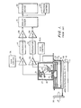
- Figure 1 shows a block diagram of a prior art apparatus to which the subject invention may be applied;
- Figure 2 is a block diagram of the apparatus circuit of Figure 1 modified in accordance with the invention;
- Figure 3 is a block diagram of the automatic calibrator of the circuit shown in Figure 2; and
- Figure 4 shows selected waveforms for a portion of the circuit of Figure 3.
- Apparatus suitable for incorporation of the subject invention is shown as prior art in Figure 1 wherein the
product 10 carried by a conveyor belt 11 is tested for colour. In a typical system the conveyor carries the product, usually a food product, from an oven or other form of processing station. It is desired to control this process by testing the colour of the product as it comes out and by readjusting the process so that the colour of the product falls within a predetermined colour range thereby indicating a satisfactory processing has been accomplished. - The product is tested by exposing it to light of a predetermined frequency range such as that emitted by the
light sources housing 15 positioned directly over the path of the product being measured. In a preferred embodiment, the light sources are of a cylindrical configuration with a centre opening through which reflected light from the product can pass back into a lens system 17 leading into an enclosedlightproof housing 18. The light strikes adichroic mirror 19 which is used because in this embodiment two different light regions are sensed to detect the properties desired. The dichroic mirror passes one predetermined light region and reflects another. The light passing through the dichroic reflector strikes afilter 20 and aphotodiode 21. The reflected light passes through a separate filter 22 and strikes aphotodiode 24. In this manner the reflected light is detected in two separate light regions of predetermined frequencies. The filtering of the reflected light must be sufficiently efficient to make the light intensities a true indication of the reflected colour of the product. - The signals resulting from the two light regions detected are subsequently compared for the generation of a ratio signal. By the generation of the ratio signal, variables are eliminated which otherwise might affect the reflected light intensities but which have little to do with the colour or processing of the product. For instance if the product quantity on the support or conveyor belt varies, the colour of the conveyor belt can show through the lesser quantity product and change the intensity of reflected light in various frequency ranges. In addition if the product is piled higher in some places than others, such that it passes closer to the light sources and the
lens assembly 20, the intensity of the reflected light can change. The overall intensities of the light sources also may diminish. By use of the two colour regions and the generation of the ratio signal, many of the effects of the aforementioned occurrences are diminished because it is assumed that these effects will change the light intensities of the two light regions in a substantially equal manner such that the calculation of the ratio signal will cancel out the effect. - The signals from the
photodetectors amplifiers integrators additional amplifiers analogue divider 31 for the generation of the signal responsive to the ratio of the intensities of the reflectance in the two selected frequency ranges. The output from the analogue divider is fed to areadout device 32 which in the normal case is a meter or recording strip chart. In addition the signal can be fed to aprocess control 34 for the purpose of regulating the process occurring immediately preceding the colour measurement. - Such systems can be used in processes wherein the product is to be heated, for instance in the blanching of french-fried potatoes or roasting peanuts wherein the colour changes with the intensity of the heating. By measuring the reflectance in predetermined frequency ranges and generating a colour ratio signal responsive thereto, the process can be regulated to produce a uniformly coloured product. In addition, such colour-sensing apparatus can be applied in potato peelers and the like to test the degree of peeling and control the peeling process so as to minimize waste while rendering an effective peeling operation. Of course there are many other uses for such controls regulated by colour-sensing apparatus.
- In the example shown in Figure 1, the process control can be used either to control the heat of a furnace (not shown) or the speed by which the conveyor carries the
product 10 for cooking. The control can either speed up or slow down the conveyor depending upon whether less or more cooking of the product is desired. The time the product spends in the oven can be regulated by use of theprocess control 34. It is also possible to control the temperature of the oven while leaving the conveyor speed constant to control the degree of cooking. Such controls are well-known. - In addition it might be necessary only to detect one colour range if that colour is a true indication of the characteristic to be tested. While a single colour would not allow cancellation of the effects of a change of intensity of the light source, still it is possible that such a light source compensation might not be necessary. For instance in the detecting of the temperatures to which metals are heated, it is possible to detect only the light radiated by the metal itself in which case it would not be necessary to detect two different colour ranges nor to provide a separate light source.
- Whether single or multiple light wavelength regions are detected, there exists the necessity to calibrate the instrument periodically because of the tendencies of the light sources to drift, the effect of the environment such as the depositing of films on the light-emitting sources or the light-transmitting members, and changes which can occur in the electronic circuitry due to temperature or long term usage. In order to calibrate the instrument previously, a target of known colour such as a
plate 35 mounted on arotatable shaft 36 is swung into position'beneath theaperture 16. By viewing thereadout device 32, the ratio signal is read and gain controls 33 and 33A can be manually adjusted to change the gain of at least one of the parallel circuits so the reading is correct for that target. In this manner manual adjustment of the instrument has been possible. - By application of the present invention to the above described apparatus, there is provided a circuit for automatically calibrating the colour apparatus. Accordingly as shown in Figure 2 there is incorporated between the
readout device 32 and theanalogue divider 31 anautomatic calibrator 36 which serves to check the calibration of the instrument periodically to allow the generation of a modifying signal to correct inaccuracies in the readout signal of the apparatus. For this purpose the automatic calibrator acts under control of acontrol calibrator 37. This control energizes anactuator 39 for rotating thetarget 35 and initiates the calibration sequence. When thetarget 35 is moved beneath thehousing 15, the readout signal is then compared to a predetermined signal and a modifying signal is generated responsive to any difference therebetween. - As shown in Figure 3 the signals from the
amplifiers analogue divider 31 which in turn supplies the resulting ratio signal to theautomatic calibrator 36. This colour signal is transmitted through theconductor 41 to ananalogue multiplier 42. In the normal operation of the apparatus,switch 44 is closed thereby allowing the signal to pass through the analogue multiplier, theswitch 44, theconductor 45, to a sample and hold 46 from which it is subsequently conducted to thereadout device 32 and theprocess control 34. Theanalogue multiplier 42 modifies the readout signal by a signal Z received through the conductor.47 to adjust the readout signal by an amount determined by the immediately previous calibration sequence. The operation of the calibration sequence will be explained hereinafter. - When calibration is desired, the
calibration control 37 signals theactuator 39 to move thedisc 35 beneath the light detecting head. At the same time a signal is transmitted through theconductor 38 to theautomatic calibrator 36 to open theswitch 44 and, through theconductor 47, to energize the sample and hold circuit 48. Theswitch 44 is opened so that during calibration, broad excursions of signal strength which might exceed the range of the readout device are not transmitted to the readout device. In addition it is desired that the process control continue operation at the previous setting, therefore the sample and holdcircuit 46 holds the setting at the previously detected level to regulate theprocess control 34. - With the energization of the sample and hold circuit 48, the analogue to
digital converter 49 and the digital toanalogue converter 50 receive the signal from theanalogue divider 31 resulting from the light reading of thedisc 35. The sample and hold circuit serves to hold that signal level and also to transmit it as a signal Y to ananalogue divider 51. Theanalogue divider 51 in the example shown receives a constant voltage signal from avoltage source 52 and performs the function (K (2.5/Y)). This function compares the signal Y to a value K which corresponds to the known signal which should be received from the head in reading the colour of thedisc 35. Thereafter the resulting modifying signal Z generated by the analogue divider is fed through theconductor 47 to theanalogue multiplier 42. - The calibration control energizes the
actuator 39 to move thedisc 35 from beneath thelight detecting head 15. At the same time theswitch 44 is closed. With the subsequent reading of the colour of a product passing along the conveyor 11, the resulting ratio signal is generated by theanalogue divider 31 in the manner previously described and transmitted through theconductors analogue multiplier 42. The sample and hold circuit, in retaining the previous signal resulting from the reading of thedisc 35, transmits the signal Y to the analogue divider which in turn generates the modifying signal Z received by the analogue multiplier. The analogue multiplier modifies the incoming ratio signal with the resulting modified signal being transmitted through theswitch 44, the sample and holdcircuit 46 to thereadout device 32 and theprocess control 34. - Thus it can be seen that the calibrating sequence serves to generate a modifying signal which is retained and used for correcting all subsequent ratio signals generated by the colour apparatus. Whether or not the signal received from the colour apparatus is a result of a direct reading of a colour or the result of the generation of a ratio as described herein, the automatic calibrator serves to adjust such signals for greater accuracy of colour measurement. The modifying signal 2 remains constant until the next calibration sequence is completed.
- One embodiment of the calibration control is shown in Figure 3. As shown, the calibration sequence is initiated by a
timer 54 which triggers a pair of one-shots waveform 57. In this instance the low logic signal from the timer causes the one shot 55 to transmit thesignal 58 to energize theactuator 39 for a time period of five seconds. At the same time the one shot 56 is energized to activate the sample and holdcircuit 46 by thewaveform 59. This maintains theprocess control 34 at the previous setting while theswitch 44 is opened. - With the
calibration disc 35 moved into the viewing area beneath thehousing 15, the analogue to digital converter is activated by asignal 60 transmitted by the one shot 61 through theconductor 47 to perform a conversion cycle. Thus the calibration signal Z is generated in the manner previously described. Thereafter the one shot 61 times out at approximately the same time as the one shot 55 to deactivate theconverter 49 and retrieve thedisc 35. Also theswitch 44 is closed followed by deactivation of the sample and hold by the timing out of the one shot 56. - Thus the calibration sequence is completed to be repeated again when the
timer 54 again generates a low logic signal. Other methods of triggering the calibration sequence could also be used such as a counter for detecting product quantity passing thehousing 15.
Claims (9)
1. Apparatus for measuring the colour of a product, comprising:
a colour detecting head for detecting light radiating from the product and for generating a colour signal responsive to the colour of the product;
a target of known colour;
means to detect the colour of said target by said head for generating a first colour signal responsive thereto;
means to generate a predetermined signal indicating the actual colour of said target;
means to compare the first colour signal and the predetermined signal to generate a modifier signal; and
means to modify all subsequent colour signals with said modifier signal to calibrate said apparatus.
2. Apparatus for measuring the colour of a product, comprising:
a colour detecting head for detecting light reflecting from the product and for generating a colour signal responsive to the colour of said product;
a target of known colour;
means to detect the colour of said target by said head and to generate a first colour signal responsive thereto;
means to generate a predetermined signal corresponding to the colour of said target;
means to compare the predetermined signal and the colour signal responsive to the target to generate a modifier signal responsive to the difference therebetween; and
means to modify all subsequent colour signals by said modifier signal thereby to calibrate said apparatus.
3. Apparatus as defined in Claim 1 or 2 wherein said colour detecting head includes a light source for directing light of a preselected wavelength onto said product.
4. Apparatus as defined in Claim 3 including means for moving said target between the colour detecting head and the product for the generation of said modifier signal.
5. Apparatus for monitoring the colour of a product, comprising:
a colour detecting head for focusing light of preselected wavelengths on the product and for detecting and generating a colour signal responsive to the wavelength of the reflected light;
a readout device for indicating the colour signal;
a target of known colour and means for focusing the light from the head thereon to generate a second colour signal; and
means adjusting the value of said second colour signal to a predetermined value comprising:
circuit means for receiving the second colour signal resulting from the light being focused on the target;
means to generate a predetermined signal which corresponds in value to a normal signal indicating the colour of the known target;
means to compare the second colour signal to the predetermined signal to generate a modifier signal changing the second colour signal to the value of the predetermined signal; and
means to store said modifier signal and to correct all subsequent colour signals with the modifier signal thereby to calibrate said apparatus.
6. Apparatus as defined in Claim 5 wherein said colour detecting head includes a light source for directing light of a preselected wavelength onto said product.
7. Apparatus as defined in Claim 5 or 6 wherein said readout device is disabled while said second colour signal is being generated.
8. Apparatus as defined in Claim 5, 6 or 7 wherein said means for fccusing the light from the head ontc said target includes means for moving the target to a position between the head and the product.
9. A method of calibrating a colour measuring apparatus having a colour detecting head for generating a colour signal responsive tc the colour of a product on which the head is focused, comprising the steps of:
focusing the head on a target of predetermined colour to generate a first colour signal:
generating 2 predetermined colour signal responsive to the actual colour of the target;
comparing the first colour signal and said predetermined colour signal to generate a modifier signal; and
modifying all subsequent colour signals with said modifier signal to calibrate said colour measuring apparatus.
Applications Claiming Priority (2)
| Application Number | Priority Date | Filing Date | Title |
|---|---|---|---|
| US955980 | 1978-10-30 | ||
| US05/955,980 US4259020A (en) | 1978-10-30 | 1978-10-30 | Automatic calibration control for color grading apparatus |
Publications (1)
| Publication Number | Publication Date |
|---|---|
| EP0010940A1 true EP0010940A1 (en) | 1980-05-14 |
Family
ID=25497629
Family Applications (1)
| Application Number | Title | Priority Date | Filing Date |
|---|---|---|---|
| EP79302357A Ceased EP0010940A1 (en) | 1978-10-30 | 1979-10-29 | Apparatus for measuring the colour of a product |
Country Status (3)
| Country | Link |
|---|---|
| US (1) | US4259020A (en) |
| EP (1) | EP0010940A1 (en) |
| CA (1) | CA1116427A (en) |
Cited By (7)
| Publication number | Priority date | Publication date | Assignee | Title |
|---|---|---|---|---|
| EP0081702A1 (en) * | 1981-11-25 | 1983-06-22 | Kollmorgen Technologies Corporation | Electro-optical system for color monitoring |
| US4718558A (en) * | 1984-10-17 | 1988-01-12 | Xeltron, S.A. | Process and apparatus for sorting samples of material |
| US5090576A (en) * | 1988-12-19 | 1992-02-25 | Elbicon N.V. | Method and apparatus for sorting a flow of objects as a function of optical properties of the objects |
| EP0530412A1 (en) * | 1991-09-03 | 1993-03-10 | Sortex Limited | Sorting machine |
| US5333739A (en) * | 1992-03-27 | 1994-08-02 | Bodenseewerk Geratechnik GmbH | Method and apparatus for sorting bulk material |
| EP1782046A1 (en) * | 2004-07-28 | 2007-05-09 | CNH Belgium N.V. | Apparatus and method for analysing the composition of crop in a crop-conveying machine |
| DE102004021448B4 (en) * | 2004-04-30 | 2016-12-29 | Carl Zeiss Spectroscopy Gmbh | Spectrometric reflection probe and method for its internal recalibration |
Families Citing this family (21)
| Publication number | Priority date | Publication date | Assignee | Title |
|---|---|---|---|---|
| JPS6311933Y2 (en) * | 1980-12-09 | 1988-04-06 | ||
| US4540286A (en) * | 1982-06-03 | 1985-09-10 | Satake Engineering Co., Ltd. | Apparatus for continuously measuring the degree of milling of grains |
| DE3315377A1 (en) * | 1983-02-19 | 1984-08-23 | Dr. Bruno Lange Gmbh, 1000 Berlin | Colorimeter |
| DE3330817A1 (en) * | 1983-08-26 | 1985-03-14 | Holstein Und Kappert Gmbh, 4600 Dortmund | DEVICE FOR READINESS REVIEW OF INSPECTION MACHINES |
| US4707138A (en) * | 1985-06-03 | 1987-11-17 | Filper Industries, Inc. | Color measuring and control device |
| JPH07114180B2 (en) * | 1985-11-25 | 1995-12-06 | 富士通株式会社 | Semiconductor exposure pattern data inspection method and inspection apparatus |
| US4773761A (en) * | 1985-12-16 | 1988-09-27 | Minolta Camera Kabushiki Kaisha | Photoelectric colorimeter |
| US4813000A (en) * | 1986-07-09 | 1989-03-14 | Jones-Blair Company | Computerized color matching |
| NL9200236A (en) * | 1992-02-07 | 1993-09-01 | Aweta Bv | METHOD AND APPARATUS FOR MEASURING THE COLOR DISTRIBUTION OF AN ARTICLE |
| WO1994001755A1 (en) * | 1992-07-02 | 1994-01-20 | Michael Fredrick Feasey | Method and calibration device for calibrating computer monitors used in the printing and textile industries |
| US5757474A (en) * | 1993-05-10 | 1998-05-26 | Midwest Research Institute | System for characterizing semiconductor materials and photovoltaic devices through calibration |
| US6567159B1 (en) * | 1999-10-13 | 2003-05-20 | Gaming Analysis, Inc. | System for recognizing a gaming chip and method of use |
| US20010048765A1 (en) * | 2000-02-29 | 2001-12-06 | Steven Yi | Color characterization for inspection of a product having nonuniform color characteristics |
| JP2002022537A (en) * | 2000-07-07 | 2002-01-23 | Hokkei Industries Co Ltd | Color recognition device |
| US10318138B2 (en) | 2011-03-11 | 2019-06-11 | Intelligent Agricultural Solutions Llc | Harvesting machine capable of automatic adjustment |
| US9629308B2 (en) | 2011-03-11 | 2017-04-25 | Intelligent Agricultural Solutions, Llc | Harvesting machine capable of automatic adjustment |
| US9631964B2 (en) | 2011-03-11 | 2017-04-25 | Intelligent Agricultural Solutions, Llc | Acoustic material flow sensor |
| US10321624B2 (en) | 2011-03-11 | 2019-06-18 | Intelligent Agriculture Solutions LLC | Air seeder manifold system |
| US9699447B2 (en) | 2012-11-26 | 2017-07-04 | Frito-Lay North America, Inc. | Calibration of a dynamic digital imaging system for detecting defects in production stream |
| US10085379B2 (en) | 2014-09-12 | 2018-10-02 | Appareo Systems, Llc | Grain quality sensor |
| EP3190866A4 (en) | 2014-09-12 | 2018-05-02 | Intelligent Agricultural Solutions LLC | Acoustic material flow sensor |
Citations (9)
| Publication number | Priority date | Publication date | Assignee | Title |
|---|---|---|---|---|
| US3646331A (en) * | 1970-09-03 | 1972-02-29 | Kollmorgen Corp | Automatic 100{11 line adjustment of spectrophotometers |
| US3817628A (en) * | 1972-08-17 | 1974-06-18 | Hoffmann La Roche | Reflectometer for on-line analysis of granular powders |
| FR2212539A1 (en) * | 1972-12-27 | 1974-07-26 | Magnuson Eng Inc | |
| US3867039A (en) * | 1971-04-15 | 1975-02-18 | Petty Ray Geophysical Inc | Color monitor for continuous process control |
| US3899415A (en) * | 1974-03-29 | 1975-08-12 | Petty Ray Geophysical Inc | Sorting machine with digital error correction |
| US3998555A (en) * | 1973-10-18 | 1976-12-21 | Genevieve I. Hanscom | Color grading apparatus |
| FR2327524A1 (en) * | 1975-10-10 | 1977-05-06 | Ibm | METHOD OF CALIBRATION OF A SPECTROPHOTOMETER |
| FR2351407A1 (en) * | 1976-05-13 | 1977-12-09 | Magnuson Eng Inc | COLOR CONTROL UNIT INCLUDING AN INFRARED LIGHT SOURCE |
| US4093991A (en) * | 1977-01-26 | 1978-06-06 | Hunter Associates Laboratory, Inc. | Spectrophotometer-digital data processing system for appearance measurements providing fast and accurate standardization, ease of use for different appearance measurements and fast response |
Family Cites Families (1)
| Publication number | Priority date | Publication date | Assignee | Title |
|---|---|---|---|---|
| US3680957A (en) * | 1967-10-10 | 1972-08-01 | Shimadzu Corp | Automatic spectrophotometer |
-
1978
- 1978-10-30 US US05/955,980 patent/US4259020A/en not_active Expired - Lifetime
-
1979
- 1979-10-24 CA CA000338315A patent/CA1116427A/en not_active Expired
- 1979-10-29 EP EP79302357A patent/EP0010940A1/en not_active Ceased
Patent Citations (9)
| Publication number | Priority date | Publication date | Assignee | Title |
|---|---|---|---|---|
| US3646331A (en) * | 1970-09-03 | 1972-02-29 | Kollmorgen Corp | Automatic 100{11 line adjustment of spectrophotometers |
| US3867039A (en) * | 1971-04-15 | 1975-02-18 | Petty Ray Geophysical Inc | Color monitor for continuous process control |
| US3817628A (en) * | 1972-08-17 | 1974-06-18 | Hoffmann La Roche | Reflectometer for on-line analysis of granular powders |
| FR2212539A1 (en) * | 1972-12-27 | 1974-07-26 | Magnuson Eng Inc | |
| US3998555A (en) * | 1973-10-18 | 1976-12-21 | Genevieve I. Hanscom | Color grading apparatus |
| US3899415A (en) * | 1974-03-29 | 1975-08-12 | Petty Ray Geophysical Inc | Sorting machine with digital error correction |
| FR2327524A1 (en) * | 1975-10-10 | 1977-05-06 | Ibm | METHOD OF CALIBRATION OF A SPECTROPHOTOMETER |
| FR2351407A1 (en) * | 1976-05-13 | 1977-12-09 | Magnuson Eng Inc | COLOR CONTROL UNIT INCLUDING AN INFRARED LIGHT SOURCE |
| US4093991A (en) * | 1977-01-26 | 1978-06-06 | Hunter Associates Laboratory, Inc. | Spectrophotometer-digital data processing system for appearance measurements providing fast and accurate standardization, ease of use for different appearance measurements and fast response |
Cited By (8)
| Publication number | Priority date | Publication date | Assignee | Title |
|---|---|---|---|---|
| EP0081702A1 (en) * | 1981-11-25 | 1983-06-22 | Kollmorgen Technologies Corporation | Electro-optical system for color monitoring |
| US4718558A (en) * | 1984-10-17 | 1988-01-12 | Xeltron, S.A. | Process and apparatus for sorting samples of material |
| US5090576A (en) * | 1988-12-19 | 1992-02-25 | Elbicon N.V. | Method and apparatus for sorting a flow of objects as a function of optical properties of the objects |
| EP0530412A1 (en) * | 1991-09-03 | 1993-03-10 | Sortex Limited | Sorting machine |
| US5333739A (en) * | 1992-03-27 | 1994-08-02 | Bodenseewerk Geratechnik GmbH | Method and apparatus for sorting bulk material |
| DE102004021448B4 (en) * | 2004-04-30 | 2016-12-29 | Carl Zeiss Spectroscopy Gmbh | Spectrometric reflection probe and method for its internal recalibration |
| EP1782046A1 (en) * | 2004-07-28 | 2007-05-09 | CNH Belgium N.V. | Apparatus and method for analysing the composition of crop in a crop-conveying machine |
| EP1782046B1 (en) * | 2004-07-28 | 2018-09-12 | CNH Industrial Belgium nv | Apparatus and method for analysing the composition of crop in a crop-conveying machine |
Also Published As
| Publication number | Publication date |
|---|---|
| US4259020A (en) | 1981-03-31 |
| CA1116427A (en) | 1982-01-19 |
Similar Documents
| Publication | Publication Date | Title |
|---|---|---|
| US4259020A (en) | Automatic calibration control for color grading apparatus | |
| US4057352A (en) | Color grading apparatus utilizing infrared light source | |
| US4707138A (en) | Color measuring and control device | |
| EP1197742B1 (en) | Side multiple-lamp on-line inside quality inspecting device | |
| US3867039A (en) | Color monitor for continuous process control | |
| US4627008A (en) | Optical quantitative analysis using curvilinear interpolation | |
| US4063822A (en) | System for detecting a first light transmissive substance, such as for instance blood, in a second light transmissive, different substance | |
| JPS6236170B2 (en) | ||
| EP0014301B1 (en) | Level measurement device | |
| GB2498086A (en) | Non-destructive detection of defects in fruits and vegetables | |
| US7545487B2 (en) | Inspection of eggs in the presence of blood | |
| US3458261A (en) | Pulsed light photometric apparatus for measuring light characteristics of moving materials | |
| US6960769B2 (en) | Infrared measuring apparatus and method for on-line application in manufacturing processes | |
| JP3056037B2 (en) | Optical measurement method and device | |
| EP0386123B1 (en) | An apparatus for colour control of objects | |
| MXPA06004811A (en) | Spectrophotometer. | |
| US3735143A (en) | Color monitoring apparatus | |
| JPH03120445A (en) | Automatic fluorescence intensity measuring instrument | |
| JP3423518B2 (en) | Moisture content detection device / moisture content measurement method and moisture content measurement device | |
| US5873982A (en) | Method and apparatus of discriminating coal species | |
| JP3243039B2 (en) | Calibration method of coaxial reflection type measuring device and coaxial reflection type measuring device | |
| HU192395B (en) | Optical reflexion concentration meter | |
| JPH1082739A (en) | Method and apparatus for inspecting internal quality of vegetables and fruits or the like | |
| EP0051899A1 (en) | Apparatus for automatically detecting and evaluating the characteristics of prints | |
| JPH0979978A (en) | Nondestructive component measuring apparatus for vegetable and fruit |
Legal Events
| Date | Code | Title | Description |
|---|---|---|---|
| PUAI | Public reference made under article 153(3) epc to a published international application that has entered the european phase |
Free format text: ORIGINAL CODE: 0009012 |
|
| AK | Designated contracting states |
Designated state(s): DE FR GB |
|
| 17P | Request for examination filed |
Effective date: 19801107 |
|
| STAA | Information on the status of an ep patent application or granted ep patent |
Free format text: STATUS: THE APPLICATION HAS BEEN REFUSED |
|
| 18R | Application refused |
Effective date: 19840106 |
|
| RIN1 | Information on inventor provided before grant (corrected) |
Inventor name: BABB, RAYMOND E. |