EP0012912A1 - Thin film magnetic transducers - Google Patents
Thin film magnetic transducers Download PDFInfo
- Publication number
- EP0012912A1 EP0012912A1 EP79105063A EP79105063A EP0012912A1 EP 0012912 A1 EP0012912 A1 EP 0012912A1 EP 79105063 A EP79105063 A EP 79105063A EP 79105063 A EP79105063 A EP 79105063A EP 0012912 A1 EP0012912 A1 EP 0012912A1
- Authority
- EP
- European Patent Office
- Prior art keywords
- layers
- pole tip
- region
- magnetic
- tip region
- Prior art date
- Legal status (The legal status is an assumption and is not a legal conclusion. Google has not performed a legal analysis and makes no representation as to the accuracy of the status listed.)
- Granted
Links
Images

Classifications
-
- G—PHYSICS
- G11—INFORMATION STORAGE
- G11B—INFORMATION STORAGE BASED ON RELATIVE MOVEMENT BETWEEN RECORD CARRIER AND TRANSDUCER
- G11B5/00—Recording by magnetisation or demagnetisation of a record carrier; Reproducing by magnetic means; Record carriers therefor
- G11B5/127—Structure or manufacture of heads, e.g. inductive
- G11B5/31—Structure or manufacture of heads, e.g. inductive using thin films
- G11B5/3109—Details
- G11B5/313—Disposition of layers
-
- G—PHYSICS
- G11—INFORMATION STORAGE
- G11B—INFORMATION STORAGE BASED ON RELATIVE MOVEMENT BETWEEN RECORD CARRIER AND TRANSDUCER
- G11B5/00—Recording by magnetisation or demagnetisation of a record carrier; Reproducing by magnetic means; Record carriers therefor
- G11B5/127—Structure or manufacture of heads, e.g. inductive
- G11B5/31—Structure or manufacture of heads, e.g. inductive using thin films
- G11B5/3109—Details
- G11B5/3116—Shaping of layers, poles or gaps for improving the form of the electrical signal transduced, e.g. for shielding, contour effect, equalizing, side flux fringing, cross talk reduction between heads or between heads and information tracks
Definitions
- This invention relates to thin film magnetic transducers for recording and reading magnetic transitions on a moving magnetic recording medium.
- U.S. Patent 3,700,827 discloses a magnetic head with a thin film yoke structure that narrows from a back region to a pole tip region.
- a separate ferrite magnetic core interconnects the yoke pieces at the back region.
- a wire coil encircles the magnetic core for activating the pole pieces during recording and transmitting electrical pulses activated in the coil during reading of magnetic transitions from a magnetic recording medium.
- U.S. Patent 4,016,601 discloses an integrated magnetic head assembly wherein the pole pieces have a reduced width in the pole tip region and a flat conductor winding coil has a branch inserted between the pole piece layers.
- the reduction in width in the pole tip region is achieved by etch removal of concave portions of the substrate and pole pieces, such that the distance between the end of the pole tip and the wide portion of the yoke structure is greater than the thickness of one of the magnetic layers plus the magnetic gap.
- the present invention provides a thin film magnetic transducer of the kind that can be used for both reading and writing with respect to a track on a magnetic recording medium and that is formed of layers built up by deposition on a deposition surface of a non-magnetic substrate, an air bearing surface (ABS) being provided at right angles to the deposition surface, the deposited layers including two layers of magnetic material defining a yoke with a pole tip region, with a transducing gap at the air bearing surface (ABS), and a back region (B) and a read/write coil in coupling juxtaposition relative to the back region (B) characterised in that (a) the layers at the pole tip region (P), for a distance (D) from the air bearing surface (ABS) parallel to the deposition surface, are of width (W) parallel to both surfaces and (b) the thickness and width of the layers in the back region (B) are greater than those dimensions of the layers on the pole tip region, the increase in width being accommodate by a taper of angle 0 whereby, in the unit
- the aforementioned prior art does not suggest the improved thin film magnetic transducer of the present invention wherein resolution is maximized during reading by providing a pole tip region P of preselected constant relatively narrow width W comprising two thin magnetic layers that extend in a direction normal to the magnetic medium.
- the effects of spurious signals from adjacent tracks on the medium are minimized by having the pole tip region extend a distance at least 5/d, where d is the recording density; however, to maximize transducer efficiency, said distance should not be increased significantly above 5/d.
- Saturation of the yoke structure with applied current is opposed and efficiency of the transducer is enhanced during recording by increasing the cross-sectional area of the yoke structure in the back region B by progressively increasing its width rearward of the pole tip region and concurrently increasing the thickness of said magnetic layers at least about 60%.
- a thin film magnetic transducer comprises a flat conductor coil 10 having a plurality of turns 10a to h plated in an elliptical pattern between two layers 11,12 of insulating material.
- a yoke structure 13 having a pole tip region P and a back region B, and formed from two layers 14, 15 of a magnetic material, such as Permalloy. These layers 14, 15 are separated by insulating layers 11, 12, except (a) at a back closure 16 in back region B, where they make physical contact, and (b) at the pole tip region P where they are spaced by a thin layer 17 of non-magnetic material to form a transducing gap 18.
- the end of transducing gap 18 coincides with an air bearing surface (ABS) formed on a non-magnetic ceramic slider 20 on which the above-described layers are deposited.
- Transducer gap 18 interacts in air bearing relation with a magnetic recording medium (not shown), such as a rotatable magnetic disk, when the latter rotates and the transducer gap flies closely adjacent to the recording medium.
- the transducer further comprises a member 21 that makes electrical contact at 22 with the central portion of coil 10, the outermost turn of coil 10 terminating in an enlarged area to constitute a second electrical contact 23.
- Member 21 is connected to external circuitry (not shown) for processing data signals during recording and reading.
- Yoke structure 13 is fabricated in the following manner. Magnetic layer 14 is deposited on a non-magnetic ceramic substrate which will eventually provide slider 20 in two stages, using appropriate masks, to provide a deposit of reduced thickness in pole tip region P. Then the non-magnetic layer 17 is deposited on layer 14 except in that part of the back region B which will eventually form the back closure 16. Insulating layer 11 is now deposited over the non-magnetic layer 17 except at transducer gap 18. Elliptically spiralling turns 10a to h of continuous flat conductor coil 10 are plated onto insulating layer 11. Insulating layer 12 is deposited over the coil. Magnetic layer 15 is deposited over the now-insulated coil 10 and the exposed area of layer 14 corresponding to back closure 16, where it makes physical contact with magnetic layer 14. Layer 15 is deposited in two stages, using appropriate masks, so that its thickness in back region B is greater than that in pole tip region P.
- Pole tip region P has a preselected substantially constant width W (FIG. 1) which is equal to or slightly less than the width of a track on the associated rotatable magnetic medium.
- the pole tip region extends a relatively short distance D normal to the air bearing surface and, hence, in use, to the magnetic medium, to maximize resolution of transitions during reading.
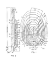
- Pole tip region P consists of a pole tip that extends from the ABS to a "zero throat point" X (FIG. 2), and a pole tip extension that extends from point X to an "optimum transition point" Y. Between these points X and Y, which is where the magnetic layers 14, 15 contact the coil-insulatin layers 11, 12, magnetic layer 15 diverges progressively from the plane of slider 20.
- pole tip region P nevertheless preferably is maintained substantially constant at width W parallel to the planes of the slider 20 and the air bearing surface ABS (see FIG. 1) between points X and Y.
- the thickness of magnetic layers 14, 15 increases significantly, preferably by about at least 60% relative to the thickness in the pole tip region P. This is to oppose saturation of yoke structure 13 when current is applied to coil 10 and to enhance efficiency of the transducer during recording by increasing the cross-sectional area of the yoke structure.
- the cross-sectional area of the yoke structure 13 is also increased by having the width of both layers 14, 15 progressively increase, preferably by having the edges of these layers diverge progressively rearward at an angle ⁇ from point Y (see FIG. 1) terminating in a wide end Z just beyond back gap 16.
- Yoke structure 13 thus has a configuration, in plan view, similar to that of a truncated triangle (back region B) which joins at its small dimension end a narrow rectangle (pole tip region P), giving an overall appearance similar to that of a ping-pong paddle.
- the diverging edges, as they approach wide end Z of back region B are curved as illustrated but this curvature is optional.
- Zero throat point X is that point at which the thickness of pole tip region P would begin to increase if air bearing surface ABS were to proceed further toward point Y.
- Transition point Y is that point at which the thickness of the magnetic layers 14, 15 increases and at which the magnetic layers begin to diverge at the angle ⁇ and at which saturation occurs.
- the thickness of magnetic layers 14, 15 is substantially constant between the ABS and transition point Y. If desired, however, and fabrication techniques permit, the thickness of layers 14, 15 might be increased either gradually cr abruptly starting somewhere to the above point X; or alternatively, the thickness of layer 14 (but not 15) might be increased gradually or abruptly somewhere above point X. In any event, it is imperative that the layers 14, 15 be of the aforementioned preselected substantially constant small thickness at least in that portion of the pole tip region between the ABS and zero threat point X.
- This distance D has to be at least equal to 5/d, where d is the recording density on the magnetic medium. This is because with D at least 5/d, the spurious fields from adjacent tracks will be sufficiently weak as not to adversely influence recording or reading of transitions.
- the distance D should preferably not exceed 18 microns, with the dimension from ABS to point X being not more than 3 microns and the dimension from X to Y being about 12 to 15 microns.
- yoke structure 13 has a pole tip region P of a predetermined constant width corresponding substantially to the width of a track on the recording medium, with at least the portion between the ABS and point X being of a constant preselected small thickness, and said pole tip region extending a relatively short distance D normal to the magnetic medium, thereby to maximize resolution of transitions during reading from the medium.
- This distance D must, however, be long enough to keep off-track reading at an acceptably low level.
- the yoke structure of the improved transducer also comprises a back region B that increases progressively in width from said predetermined constant width and has a back gap 16 substantially centred within the yoke structure adjacent its wider end Z; and the layers 14, 15 of magnetic material in the back region are at least about 60% thicker than their smaller thickness within the pole tip region P, thereby to desirably oppose saturation of the yoke structure with applied current and enhance the efficiency of the transducer during recording by increasing the cross-sectional area of the yoke structure.
Abstract
Description
- This invention relates to thin film magnetic transducers for recording and reading magnetic transitions on a moving magnetic recording medium.
- Various configurations have heretofore been proposed to enhance efficiency of magnetic transducers during recording and enhance the resolution of transitions during reading.
- U.S. Patents 3,700,827 and 4,016,601 constitute the most pertinent prior art presently known to applicants.
- U.S. Patent 3,700,827 discloses a magnetic head with a thin film yoke structure that narrows from a back region to a pole tip region. A separate ferrite magnetic core interconnects the yoke pieces at the back region. A wire coil encircles the magnetic core for activating the pole pieces during recording and transmitting electrical pulses activated in the coil during reading of magnetic transitions from a magnetic recording medium.
- U.S. Patent 4,016,601 discloses an integrated magnetic head assembly wherein the pole pieces have a reduced width in the pole tip region and a flat conductor winding coil has a branch inserted between the pole piece layers. The reduction in width in the pole tip region is achieved by etch removal of concave portions of the substrate and pole pieces, such that the distance between the end of the pole tip and the wide portion of the yoke structure is greater than the thickness of one of the magnetic layers plus the magnetic gap.
- The present invention provides a thin film magnetic transducer of the kind that can be used for both reading and writing with respect to a track on a magnetic recording medium and that is formed of layers built up by deposition on a deposition surface of a non-magnetic substrate, an air bearing surface (ABS) being provided at right angles to the deposition surface, the deposited layers including two layers of magnetic material defining a yoke with a pole tip region, with a transducing gap at the air bearing surface (ABS), and a back region (B) and a read/write coil in coupling juxtaposition relative to the back region (B) characterised in that (a) the layers at the pole tip region (P), for a distance (D) from the air bearing surface (ABS) parallel to the deposition surface, are of width (W) parallel to both surfaces and (b) the thickness and width of the layers in the back region (B) are greater than those dimensions of the layers on the pole tip region, the increase in width being accommodate by a taper of angle 0 whereby, in the unitary deposited structure, reading definition is provided by the polo tip region (P) and resistance to writing saturation is provided by the back region (B).
- The aforementioned prior art does not suggest the improved thin film magnetic transducer of the present invention wherein resolution is maximized during reading by providing a pole tip region P of preselected constant relatively narrow width W comprising two thin magnetic layers that extend in a direction normal to the magnetic medium. The effects of spurious signals from adjacent tracks on the medium are minimized by having the pole tip region extend a distance at least 5/d, where d is the recording density; however, to maximize transducer efficiency, said distance should not be increased significantly above 5/d. Saturation of the yoke structure with applied current is opposed and efficiency of the transducer is enhanced during recording by increasing the cross-sectional area of the yoke structure in the back region B by progressively increasing its width rearward of the pole tip region and concurrently increasing the thickness of said magnetic layers at least about 60%.
- The invention will now be described, by way of example, with reference to the accompanying drawings in which
- FIG. 1 is a top plan view of one form of thin film magnetic transducer according to the invention;
- FIG. 2 is a sectional view, to enlarged scale, taken along the line 2-2 of FIG. 1; and
- FIG. 3 is a perspective view of the transducer.
- As illustrated in the drawings, a thin film magnetic transducer comprises a
flat conductor coil 10 having a plurality of turns 10a to h plated in an elliptical pattern between twolayers 11,12 of insulating material. - A
yoke structure 13 is provided, having a pole tip region P and a back region B, and formed from twolayers layers insulating layers 11, 12, except (a) at aback closure 16 in back region B, where they make physical contact, and (b) at the pole tip region P where they are spaced by athin layer 17 of non-magnetic material to form a transducinggap 18. The end of transducinggap 18 coincides with an air bearing surface (ABS) formed on a non-magneticceramic slider 20 on which the above-described layers are deposited.Transducer gap 18 interacts in air bearing relation with a magnetic recording medium (not shown), such as a rotatable magnetic disk, when the latter rotates and the transducer gap flies closely adjacent to the recording medium. - The transducer further comprises a
member 21 that makes electrical contact at 22 with the central portion ofcoil 10, the outermost turn ofcoil 10 terminating in an enlarged area to constitute a secondelectrical contact 23.Member 21 is connected to external circuitry (not shown) for processing data signals during recording and reading. -
Yoke structure 13 is fabricated in the following manner.Magnetic layer 14 is deposited on a non-magnetic ceramic substrate which will eventually provideslider 20 in two stages, using appropriate masks, to provide a deposit of reduced thickness in pole tip region P. Then thenon-magnetic layer 17 is deposited onlayer 14 except in that part of the back region B which will eventually form theback closure 16. Insulating layer 11 is now deposited over thenon-magnetic layer 17 except attransducer gap 18. Elliptically spiralling turns 10a to h of continuousflat conductor coil 10 are plated onto insulating layer 11.Insulating layer 12 is deposited over the coil.Magnetic layer 15 is deposited over the now-insulatedcoil 10 and the exposed area oflayer 14 corresponding toback closure 16, where it makes physical contact withmagnetic layer 14.Layer 15 is deposited in two stages, using appropriate masks, so that its thickness in back region B is greater than that in pole tip region P. - Pole tip region P has a preselected substantially constant width W (FIG. 1) which is equal to or slightly less than the width of a track on the associated rotatable magnetic medium. The pole tip region extends a relatively short distance D normal to the air bearing surface and, hence, in use, to the magnetic medium, to maximize resolution of transitions during reading. Pole tip region P consists of a pole tip that extends from the ABS to a "zero throat point" X (FIG. 2), and a pole tip extension that extends from point X to an "optimum transition point" Y. Between these points X and Y, which is where the
magnetic layers insulatin layers 11, 12,magnetic layer 15 diverges progressively from the plane ofslider 20. Note that the downturned outward edges ofinsulating layers 11, 12 are caused by some flow of the material during deposition, which results inlayer 15 having a somewhat curved cross section; but pole tip region P nevertheless preferably is maintained substantially constant at width W parallel to the planes of theslider 20 and the air bearing surface ABS (see FIG. 1) between points X and Y. - In back region B, the thickness of
magnetic layers yoke structure 13 when current is applied to coil 10 and to enhance efficiency of the transducer during recording by increasing the cross-sectional area of the yoke structure. - The cross-sectional area of the
yoke structure 13 is also increased by having the width of bothlayers back gap 16.Yoke structure 13 thus has a configuration, in plan view, similar to that of a truncated triangle (back region B) which joins at its small dimension end a narrow rectangle (pole tip region P), giving an overall appearance similar to that of a ping-pong paddle. The diverging edges, as they approach wide end Z of back region B are curved as illustrated but this curvature is optional. - Zero throat point X is that point at which the thickness of pole tip region P would begin to increase if air bearing surface ABS were to proceed further toward point Y. Transition point Y is that point at which the thickness of the
magnetic layers - It has been found by actual test that the level of pole tip induction at which saturation commences is essentially insensitive to the magnitude of angle φ provided this angle is maintained between about 30° and 60°. It was also found that the zero throat point X should be as close as possible to the ABS. Difficulties will generally be experienced in fabrication if transition point Y is moved downwards as viewed in FIG. 2 because of the sloping of the outer edges of
insulating layers 11, 12. On the other hand, if transition point Y is shifted upwards as viewed in FIG. 2, the transducer efficiency and ability to record will be reduced because the total cross-sectional area of the thick and wide back region B will be correspondingly reduced. - Note that, as preferred and as illustrated in Fig. 2, the thickness of
magnetic layers layers layers - Since saturation occurs at optimum transition point Y, it is desirable to keep the pole tip region P at the uniform width W, but keep the distance D as short as possible. This distance D, however, has to be at least equal to 5/d, where d is the recording density on the magnetic medium. This is because with D at least 5/d, the spurious fields from adjacent tracks will be sufficiently weak as not to adversely influence recording or reading of transitions.
- Thus, according to one illustrative embodiment, for a recording density of 400 flux changes per millimetre, the distance D should preferably not exceed 18 microns, with the dimension from ABS to point X being not more than 3 microns and the dimension from X to Y being about 12 to 15 microns.
- It will thus be seen that, with thin film magnetic transducer described herein,
yoke structure 13 has a pole tip region P of a predetermined constant width corresponding substantially to the width of a track on the recording medium, with at least the portion between the ABS and point X being of a constant preselected small thickness, and said pole tip region extending a relatively short distance D normal to the magnetic medium, thereby to maximize resolution of transitions during reading from the medium. This distance D must, however, be long enough to keep off-track reading at an acceptably low level. The yoke structure of the improved transducer also comprises a back region B that increases progressively in width from said predetermined constant width and has aback gap 16 substantially centred within the yoke structure adjacent its wider end Z; and thelayers
Claims (6)
Applications Claiming Priority (2)
| Application Number | Priority Date | Filing Date | Title |
|---|---|---|---|
| US05/972,104 US4190872A (en) | 1978-12-21 | 1978-12-21 | Thin film inductive transducer |
| US972104 | 1978-12-21 |
Publications (2)
| Publication Number | Publication Date |
|---|---|
| EP0012912A1 true EP0012912A1 (en) | 1980-07-09 |
| EP0012912B1 EP0012912B1 (en) | 1981-12-30 |
Family
ID=25519165
Family Applications (1)
| Application Number | Title | Priority Date | Filing Date |
|---|---|---|---|
| EP79105063A Expired EP0012912B1 (en) | 1978-12-21 | 1979-12-10 | Thin film magnetic transducers |
Country Status (9)
| Country | Link |
|---|---|
| US (1) | US4190872A (en) |
| EP (1) | EP0012912B1 (en) |
| JP (1) | JPS5584019A (en) |
| AU (1) | AU526069B2 (en) |
| BR (1) | BR7908411A (en) |
| CA (1) | CA1127298A (en) |
| DE (1) | DE2961724D1 (en) |
| ES (1) | ES487049A1 (en) |
| ZA (1) | ZA796366B (en) |
Cited By (14)
| Publication number | Priority date | Publication date | Assignee | Title |
|---|---|---|---|---|
| EP0071489A2 (en) * | 1981-07-30 | 1983-02-09 | Fujitsu Limited | A perpendicular magnetic recording and reproducing head |
| EP0078374A2 (en) * | 1981-10-30 | 1983-05-11 | International Business Machines Corporation | Thin film inductive transducer for perpendicular magnetic recording |
| EP0108386A1 (en) * | 1982-11-02 | 1984-05-16 | Nec Corporation | Buried servo recording system having dual transducers |
| DE3501810A1 (en) * | 1985-01-21 | 1986-07-24 | Siemens AG, 1000 Berlin und 8000 München | Thin-film magnetic head with a double gap for a recording medium to be vertically magnetised |
| US4672493A (en) * | 1984-05-04 | 1987-06-09 | Siemens Aktiengesellschaft | Thin-film magnetic head with a double gap for a recording medium to be magnetized vertically |
| US4710838A (en) * | 1984-12-21 | 1987-12-01 | Siemens Aktiengesellschaft | Magnetic thin-film head for a recording medium that can be magnetized vertically |
| US4740855A (en) * | 1985-10-18 | 1988-04-26 | Siemens Aktiengesellschaft | Magnetic thin-film head having a main and an auxiliary pole for vertical magnetization |
| US4742413A (en) * | 1985-12-20 | 1988-05-03 | Siemens Akteingesellschaft | Magnetic memory including a recording device and medium that can be magnetized vertically |
| US4772976A (en) * | 1984-08-27 | 1988-09-20 | Hitachi, Ltd. | Process for preparing magnetic layer and magnetic head prepared using the same |
| US4853815A (en) * | 1984-12-21 | 1989-08-01 | Siemens Aktiengesellschaft | Magnetic thin-film head on a nonmagnetic substrate for vertical mangetization |
| EP0387364A1 (en) * | 1989-03-13 | 1990-09-19 | Siemens Aktiengesellschaft | Thin film magnetic head unit |
| US4987510A (en) * | 1977-12-11 | 1991-01-22 | Siemens Aktiengesellschaft | Thin film magnet head for vertical magnetization |
| EP0548511A1 (en) * | 1991-12-18 | 1993-06-30 | Hewlett-Packard Company | Thin film inductive transducer having improved write capability |
| US5236735A (en) * | 1989-05-27 | 1993-08-17 | Tdk Corporation | Method of producing a thin film magnetic head |
Families Citing this family (58)
| Publication number | Priority date | Publication date | Assignee | Title |
|---|---|---|---|---|
| FR2455330A1 (en) * | 1979-04-25 | 1980-11-21 | Cii Honeywell Bull | MAGNETIC RESISTANCE TRANSDUCTION DEVICE |
| US4353102A (en) * | 1979-07-04 | 1982-10-05 | Matsushita Electric Industrial Co., Ltd. | Thin-film magnetic head |
| US4295173A (en) * | 1979-10-18 | 1981-10-13 | International Business Machines Corporation | Thin film inductive transducer |
| JPS5674811A (en) * | 1979-11-20 | 1981-06-20 | Matsushita Electric Ind Co Ltd | Magnetic head |
| US4375657A (en) * | 1980-11-03 | 1983-03-01 | Brock George W | Magnetic head assembly |
| JPS57117117A (en) * | 1981-01-09 | 1982-07-21 | Matsushita Electric Ind Co Ltd | Thin film magnetic head |
| US4458279A (en) * | 1981-03-23 | 1984-07-03 | Magnex Corporation | Thin film transducer and method of making same |
| JPS5819716A (en) * | 1981-07-27 | 1983-02-04 | Hitachi Ltd | Thin film magnetic head and its production |
| JPS58105025U (en) * | 1982-01-07 | 1983-07-16 | 日本ビクター株式会社 | multitrack magnetic head |
| US4458280A (en) * | 1982-01-18 | 1984-07-03 | International Business Machines Corporation | Servo writing transducer design and writing method |
| US4490766A (en) * | 1982-03-22 | 1984-12-25 | International Business Machines Corporation | Magnetic recording disk cleaning using controlled actuator motion |
| JPS5971112A (en) * | 1982-10-15 | 1984-04-21 | Comput Basic Mach Technol Res Assoc | Thin film magnetic head |
| JPS5971115A (en) * | 1982-10-15 | 1984-04-21 | Hitachi Ltd | Thin film head for vertical magnetic recording and reproduction |
| US4593334A (en) * | 1983-05-02 | 1986-06-03 | International Business Machines Corporation | Thin film transducer |
| US4589042A (en) * | 1983-06-27 | 1986-05-13 | International Business Machines Corporation | Composite thin film transducer head |
| FR2559294B1 (en) * | 1984-02-03 | 1988-08-12 | Commissariat Energie Atomique | NOVEL MAGNETIC WRITE AND READ HEAD FOR PERPENDICULAR RECORDING AND MANUFACTURING METHOD THEREOF |
| US4923574A (en) * | 1984-11-13 | 1990-05-08 | Uri Cohen | Method for making a record member with a metallic antifriction overcoat |
| US4644432A (en) * | 1985-01-28 | 1987-02-17 | International Business Machines | Three pole single element magnetic read/write head |
| US4764834A (en) * | 1985-03-22 | 1988-08-16 | Applied Magnetics Corporation | Thin film magnetic transducer having a separate magnetically conductive layer |
| US4675986A (en) * | 1985-07-29 | 1987-06-30 | International Business Machines | Electrical lapping guide for controlling the batch fabrication of thin film magnetic transducers |
| EP0218445A3 (en) * | 1985-10-01 | 1989-08-30 | Sony Corporation | Thin film magnetic heads |
| JPS62173607A (en) * | 1986-01-27 | 1987-07-30 | Hitachi Ltd | Thin film magnetic head |
| US4819111A (en) * | 1986-08-29 | 1989-04-04 | Magnetic Peripheral Inc. | Thin film head with reduced cross section in the core for causing magnetic saturation in the leading leg's throat area |
| US4839197A (en) * | 1988-04-13 | 1989-06-13 | Storage Technology Corporation | Process for fabricating thin film magnetic recording heads having precision control of the width tolerance of the upper pole tip |
| US5023738A (en) * | 1989-12-18 | 1991-06-11 | Seagate Technology, Inc. | Corrosion resistant magnetic recording read |
| NL9001147A (en) * | 1990-05-17 | 1991-12-16 | Philips Nv | THIN MOVIE MAGNETIC HEAD. |
| DE69123487T2 (en) * | 1990-05-31 | 1997-06-26 | Sony Corp | Thin film magnetic head |
| US5220471A (en) * | 1990-08-14 | 1993-06-15 | Tdk Corporation | Air bearing slider having a longitudinal groove in surface remote from recording medium |
| US5059278A (en) * | 1990-09-28 | 1991-10-22 | Seagate Technology | Selective chemical removal of coil seed-layer in thin film head magnetic transducer |
| US5240740A (en) * | 1990-11-26 | 1993-08-31 | Digital Equipment Corporation | Method of making a thin film head with minimized secondary pulses |
| JPH04214205A (en) * | 1990-12-12 | 1992-08-05 | Fuji Electric Co Ltd | Thin-film magnetic head and its production |
| US5264981A (en) * | 1991-08-14 | 1993-11-23 | International Business Machines Corporation | Multilayered ferromagnetic film and magnetic head employing the same |
| US5305165A (en) * | 1991-12-24 | 1994-04-19 | International Business Machines Corporation | Tribo-attractive contact data storage system |
| JP2544563B2 (en) * | 1992-06-19 | 1996-10-16 | 株式会社日立製作所 | Thin film magnetic head and magnetic recording device |
| JP2550829B2 (en) * | 1992-06-19 | 1996-11-06 | 株式会社日立製作所 | Thin film magnetic head and magnetic recording device |
| US5470491A (en) * | 1992-07-03 | 1995-11-28 | Mitsubishi Denki Kabushiki Kaisha | Process for producing a thin-film magnetic head having an insulation formed of a ladder-type silicone resin |
| JPH0676238A (en) * | 1992-07-08 | 1994-03-18 | Fuji Electric Co Ltd | Thin-film magnetic head |
| US5820770A (en) * | 1992-07-21 | 1998-10-13 | Seagate Technology, Inc. | Thin film magnetic head including vias formed in alumina layer and process for making the same |
| US5326429A (en) * | 1992-07-21 | 1994-07-05 | Seagate Technology, Inc. | Process for making studless thin film magnetic head |
| JP2721783B2 (en) * | 1992-08-19 | 1998-03-04 | インターナショナル・ビジネス・マシーンズ・コーポレイション | Thin-film magnetic head transducer / suspension combination system and method of manufacturing the same |
| JPH06168556A (en) * | 1992-08-25 | 1994-06-14 | Internatl Business Mach Corp <Ibm> | Combination assembly of converter and suspension part and its treatment method as well as data processor provided with said assembly |
| US5945007A (en) | 1992-10-20 | 1999-08-31 | Cohen; Uri | Method for etching gap-vias in a magnetic thin film head and product |
| US5621595A (en) * | 1992-10-20 | 1997-04-15 | Cohen; Uri | Pinched-gap magnetic recording thin film head |
| KR0129105B1 (en) * | 1993-01-08 | 1998-04-18 | 월리엄 티. 엘리스 | Method of manufacturing integral transducer-suspension assembly for longitudinal recording |
| JPH0773412A (en) * | 1993-06-24 | 1995-03-17 | Sanyo Electric Co Ltd | Thin film magnetic head |
| US5452166A (en) * | 1993-10-01 | 1995-09-19 | Applied Magnetics Corporation | Thin film magnetic recording head for minimizing undershoots and a method for manufacturing the same |
| US5462636A (en) * | 1993-12-28 | 1995-10-31 | International Business Machines Corporation | Method for chemically scribing wafers |
| US5452164A (en) * | 1994-02-08 | 1995-09-19 | International Business Machines Corporation | Thin film magnetic write head |
| US5710745A (en) * | 1995-04-07 | 1998-01-20 | Discovision Associates | Assembly having flux-directing return yoke for magneto-optical drive |
| US5703740A (en) * | 1995-08-24 | 1997-12-30 | Velocidata, Inc. | Toroidal thin film head |
| US6151194A (en) * | 1999-03-04 | 2000-11-21 | Storage Technology Corporation | Thin film inductive transducer with alumina gap positioned over coils |
| US6304414B1 (en) | 1999-07-20 | 2001-10-16 | Read-Rite Corporation | Thin film magnetic write head having an ultra-low stack height |
| JP2001319312A (en) | 2000-05-10 | 2001-11-16 | Tdk Corp | Thin-film coil, its manufacturing method, thin-film magnetic head and its manufacturing method |
| JP2002015405A (en) * | 2000-06-28 | 2002-01-18 | Tdk Corp | Thin film magnetic head and method of manufacture |
| US7100266B2 (en) * | 2001-05-16 | 2006-09-05 | Seagate Technology Llc | Method of forming a beveled writing pole of a perpendicular writing element |
| US6906893B2 (en) | 2002-10-08 | 2005-06-14 | Hitachi Global Storage Technologies | Magnetic head coil and structure for protecting same during pole notch processing |
| JP4990866B2 (en) * | 2008-10-08 | 2012-08-01 | 昭和電工株式会社 | Magnetic recording medium manufacturing method and magnetic recording / reproducing apparatus |
| JP6471975B2 (en) | 2015-07-31 | 2019-02-20 | パナソニックIpマネジメント株式会社 | Manufacturing method of three-dimensional shaped object and three-dimensional shaped object |
Citations (3)
| Publication number | Priority date | Publication date | Assignee | Title |
|---|---|---|---|---|
| US3700827A (en) * | 1970-01-31 | 1972-10-24 | Nippon Electric Co | Magnetic head including thin magnetic film separated by a gap spacer |
| US4016601A (en) * | 1975-01-10 | 1977-04-05 | Compagnie Internationale Pour L'informatique | Integrated magnetic head having pole-pieces of a reduced frontal width |
| US4078300A (en) * | 1975-01-10 | 1978-03-14 | Compagnie Internationale Pour L'informatique | Method of making an integrated magnetic head having pole-pieces of a reduced frontal width |
Family Cites Families (4)
| Publication number | Priority date | Publication date | Assignee | Title |
|---|---|---|---|---|
| US3344237A (en) * | 1967-09-26 | Desposited film transducing apparatus and method op producing the apparatus | ||
| CH405426A (en) * | 1961-12-21 | 1966-01-15 | Ibm | Magnetic head for recording and reading digital signals |
| JPS5038325B1 (en) * | 1970-12-25 | 1975-12-09 | ||
| FR2191186B1 (en) * | 1972-07-03 | 1976-01-16 | Inf Ci Interna Fr |
-
1978
- 1978-12-21 US US05/972,104 patent/US4190872A/en not_active Expired - Lifetime
-
1979
- 1979-11-09 JP JP14450179A patent/JPS5584019A/en active Granted
- 1979-11-13 CA CA339,634A patent/CA1127298A/en not_active Expired
- 1979-11-19 AU AU52951/79A patent/AU526069B2/en not_active Ceased
- 1979-11-23 ZA ZA00796366A patent/ZA796366B/en unknown
- 1979-12-10 EP EP79105063A patent/EP0012912B1/en not_active Expired
- 1979-12-10 DE DE7979105063T patent/DE2961724D1/en not_active Expired
- 1979-12-19 ES ES487049A patent/ES487049A1/en not_active Expired
- 1979-12-20 BR BR7908411A patent/BR7908411A/en not_active IP Right Cessation
Patent Citations (3)
| Publication number | Priority date | Publication date | Assignee | Title |
|---|---|---|---|---|
| US3700827A (en) * | 1970-01-31 | 1972-10-24 | Nippon Electric Co | Magnetic head including thin magnetic film separated by a gap spacer |
| US4016601A (en) * | 1975-01-10 | 1977-04-05 | Compagnie Internationale Pour L'informatique | Integrated magnetic head having pole-pieces of a reduced frontal width |
| US4078300A (en) * | 1975-01-10 | 1978-03-14 | Compagnie Internationale Pour L'informatique | Method of making an integrated magnetic head having pole-pieces of a reduced frontal width |
Cited By (23)
| Publication number | Priority date | Publication date | Assignee | Title |
|---|---|---|---|---|
| US4987510A (en) * | 1977-12-11 | 1991-01-22 | Siemens Aktiengesellschaft | Thin film magnet head for vertical magnetization |
| US4546398A (en) * | 1981-07-03 | 1985-10-08 | Fujitsu Limited | Perpendicular magnetic recording and reproducing head |
| EP0071489A2 (en) * | 1981-07-30 | 1983-02-09 | Fujitsu Limited | A perpendicular magnetic recording and reproducing head |
| EP0071489A3 (en) * | 1981-07-30 | 1983-09-07 | Fujitsu Limited | A perpendicular magnetic recording and reproducing head |
| EP0078374B1 (en) * | 1981-10-30 | 1987-04-01 | International Business Machines Corporation | Thin film inductive transducer for perpendicular magnetic recording |
| EP0078374A2 (en) * | 1981-10-30 | 1983-05-11 | International Business Machines Corporation | Thin film inductive transducer for perpendicular magnetic recording |
| EP0242887A2 (en) * | 1982-11-02 | 1987-10-28 | Nec Corporation | Buried servo recording system having dual transducers |
| EP0108386A1 (en) * | 1982-11-02 | 1984-05-16 | Nec Corporation | Buried servo recording system having dual transducers |
| EP0242887A3 (en) * | 1982-11-02 | 1988-01-07 | Nec Corporation | Buried servo recording system having dual transducers |
| US4672493A (en) * | 1984-05-04 | 1987-06-09 | Siemens Aktiengesellschaft | Thin-film magnetic head with a double gap for a recording medium to be magnetized vertically |
| EP0174144B1 (en) * | 1984-08-27 | 1991-11-27 | Hitachi, Ltd. | Process for preparing magnetic layer and magnetic head prepared using the same |
| US4772976A (en) * | 1984-08-27 | 1988-09-20 | Hitachi, Ltd. | Process for preparing magnetic layer and magnetic head prepared using the same |
| US4894098A (en) * | 1984-08-27 | 1990-01-16 | Hitachi, Ltd. | Process for preparing magnetic layer and magnetic head prepared using the same |
| US4853815A (en) * | 1984-12-21 | 1989-08-01 | Siemens Aktiengesellschaft | Magnetic thin-film head on a nonmagnetic substrate for vertical mangetization |
| EP0186032B1 (en) * | 1984-12-21 | 1989-05-24 | Siemens Aktiengesellschaft | Thin-film magnetic head for a recording medium to be perpendicularly magnetized |
| US4710838A (en) * | 1984-12-21 | 1987-12-01 | Siemens Aktiengesellschaft | Magnetic thin-film head for a recording medium that can be magnetized vertically |
| DE3501810A1 (en) * | 1985-01-21 | 1986-07-24 | Siemens AG, 1000 Berlin und 8000 München | Thin-film magnetic head with a double gap for a recording medium to be vertically magnetised |
| US4740855A (en) * | 1985-10-18 | 1988-04-26 | Siemens Aktiengesellschaft | Magnetic thin-film head having a main and an auxiliary pole for vertical magnetization |
| US4742413A (en) * | 1985-12-20 | 1988-05-03 | Siemens Akteingesellschaft | Magnetic memory including a recording device and medium that can be magnetized vertically |
| EP0387364A1 (en) * | 1989-03-13 | 1990-09-19 | Siemens Aktiengesellschaft | Thin film magnetic head unit |
| US5236735A (en) * | 1989-05-27 | 1993-08-17 | Tdk Corporation | Method of producing a thin film magnetic head |
| EP0548511A1 (en) * | 1991-12-18 | 1993-06-30 | Hewlett-Packard Company | Thin film inductive transducer having improved write capability |
| US5325254A (en) * | 1991-12-18 | 1994-06-28 | Hewlett-Packard Company | Thin film inductive transducer having improved yoke and pole tip structure |
Also Published As
| Publication number | Publication date |
|---|---|
| AU526069B2 (en) | 1982-12-16 |
| EP0012912B1 (en) | 1981-12-30 |
| ZA796366B (en) | 1980-11-26 |
| JPS5584019A (en) | 1980-06-24 |
| BR7908411A (en) | 1980-09-23 |
| ES487049A1 (en) | 1980-09-16 |
| CA1127298A (en) | 1982-07-06 |
| US4190872A (en) | 1980-02-26 |
| DE2961724D1 (en) | 1982-02-18 |
| AU5295179A (en) | 1980-06-26 |
| JPH034964B2 (en) | 1991-01-24 |
Similar Documents
| Publication | Publication Date | Title |
|---|---|---|
| EP0012912B1 (en) | Thin film magnetic transducers | |
| US4295173A (en) | Thin film inductive transducer | |
| EP0131716B1 (en) | Composite thin film transducer head | |
| US4404609A (en) | Thin film inductive transducer for perpendicular recording | |
| US5703740A (en) | Toroidal thin film head | |
| US5274521A (en) | Planar thin film magnetic head | |
| EP0012910B1 (en) | Thin film magnetic heads | |
| US4546398A (en) | Perpendicular magnetic recording and reproducing head | |
| EP0640955B1 (en) | Magnetic head assembly with write pole/shield structure | |
| US4644432A (en) | Three pole single element magnetic read/write head | |
| US6535361B2 (en) | Contact planar magnetoresistive head | |
| Bajorek et al. | An integrated magnetoresistive read, inductive write high density recording head | |
| US6151194A (en) | Thin film inductive transducer with alumina gap positioned over coils | |
| US4805058A (en) | Magnetic erasing head | |
| JPS62270015A (en) | Floating type magnetic head | |
| US4654739A (en) | Thin film magnetic head for reproducing perpendicular magnetization | |
| JPS62114113A (en) | Thin film magnetic head | |
| JPS59201211A (en) | Magnetic head | |
| JP2576536B2 (en) | Thin film magnetic head | |
| JPS5994219A (en) | Magnetic head | |
| JP2560926B2 (en) | Method of manufacturing thin film magnetic head | |
| JPH04366407A (en) | Thin-film magnetic head | |
| JPH04362506A (en) | Laminated head | |
| JPH0352124B2 (en) | ||
| JPH04366406A (en) | Thin-film magnetic head |
Legal Events
| Date | Code | Title | Description |
|---|---|---|---|
| PUAI | Public reference made under article 153(3) epc to a published international application that has entered the european phase |
Free format text: ORIGINAL CODE: 0009012 |
|
| AK | Designated contracting states |
Designated state(s): BE CH DE FR GB IT NL SE |
|
| 17P | Request for examination filed | ||
| ITF | It: translation for a ep patent filed |
Owner name: IBM - DR. ALFREDO BRAVI |
|
| GRAA | (expected) grant |
Free format text: ORIGINAL CODE: 0009210 |
|
| AK | Designated contracting states |
Designated state(s): BE CH DE FR GB IT NL SE |
|
| REF | Corresponds to: |
Ref document number: 2961724 Country of ref document: DE Date of ref document: 19820218 |
|
| ITTA | It: last paid annual fee | ||
| PGFP | Annual fee paid to national office [announced via postgrant information from national office to epo] |
Ref country code: SE Payment date: 19931220 Year of fee payment: 15 |
|
| PG25 | Lapsed in a contracting state [announced via postgrant information from national office to epo] |
Ref country code: SE Effective date: 19941211 |
|
| EAL | Se: european patent in force in sweden |
Ref document number: 79105063.6 |
|
| EUG | Se: european patent has lapsed |
Ref document number: 79105063.6 |
|
| PGFP | Annual fee paid to national office [announced via postgrant information from national office to epo] |
Ref country code: BE Payment date: 19961119 Year of fee payment: 18 |
|
| PGFP | Annual fee paid to national office [announced via postgrant information from national office to epo] |
Ref country code: CH Payment date: 19970325 Year of fee payment: 18 |
|
| PG25 | Lapsed in a contracting state [announced via postgrant information from national office to epo] |
Ref country code: CH Free format text: LAPSE BECAUSE OF NON-PAYMENT OF DUE FEES Effective date: 19971231 Ref country code: BE Free format text: LAPSE BECAUSE OF NON-PAYMENT OF DUE FEES Effective date: 19971231 |
|
| PGFP | Annual fee paid to national office [announced via postgrant information from national office to epo] |
Ref country code: NL Payment date: 19971231 Year of fee payment: 19 |
|
| BERE | Be: lapsed |
Owner name: INTERNATIONAL BUSINESS MACHINES CORP. Effective date: 19971231 |
|
| REG | Reference to a national code |
Ref country code: CH Ref legal event code: PL |
|
| PGFP | Annual fee paid to national office [announced via postgrant information from national office to epo] |
Ref country code: GB Payment date: 19981124 Year of fee payment: 20 |
|
| PGFP | Annual fee paid to national office [announced via postgrant information from national office to epo] |
Ref country code: FR Payment date: 19981207 Year of fee payment: 20 |
|
| PGFP | Annual fee paid to national office [announced via postgrant information from national office to epo] |
Ref country code: DE Payment date: 19981215 Year of fee payment: 20 |
|
| PG25 | Lapsed in a contracting state [announced via postgrant information from national office to epo] |
Ref country code: NL Free format text: LAPSE BECAUSE OF NON-PAYMENT OF DUE FEES Effective date: 19990701 |
|
| NLV4 | Nl: lapsed or anulled due to non-payment of the annual fee |
Effective date: 19990701 |
|
| PG25 | Lapsed in a contracting state [announced via postgrant information from national office to epo] |
Ref country code: GB Free format text: LAPSE BECAUSE OF EXPIRATION OF PROTECTION Effective date: 19991209 |
|
| REG | Reference to a national code |
Ref country code: GB Ref legal event code: PE20 Effective date: 19991209 |
|
| REG | Reference to a national code |
Ref country code: FR Ref legal event code: TP |
|
| PLBE | No opposition filed within time limit |
Free format text: ORIGINAL CODE: 0009261 |
|
| STAA | Information on the status of an ep patent application or granted ep patent |
Free format text: STATUS: NO OPPOSITION FILED WITHIN TIME LIMIT |