EP0014150A2 - Cervical biopsy sampling instrument - Google Patents
Cervical biopsy sampling instrument Download PDFInfo
- Publication number
- EP0014150A2 EP0014150A2 EP80400105A EP80400105A EP0014150A2 EP 0014150 A2 EP0014150 A2 EP 0014150A2 EP 80400105 A EP80400105 A EP 80400105A EP 80400105 A EP80400105 A EP 80400105A EP 0014150 A2 EP0014150 A2 EP 0014150A2
- Authority
- EP
- European Patent Office
- Prior art keywords
- rod
- scraper element
- tube
- stop
- scraper
- Prior art date
- Legal status (The legal status is an assumption and is not a legal conclusion. Google has not performed a legal analysis and makes no representation as to the accuracy of the status listed.)
- Granted
Links
Images
Classifications
-
- A—HUMAN NECESSITIES
- A61—MEDICAL OR VETERINARY SCIENCE; HYGIENE
- A61B—DIAGNOSIS; SURGERY; IDENTIFICATION
- A61B10/00—Other methods or instruments for diagnosis, e.g. instruments for taking a cell sample, for biopsy, for vaccination diagnosis; Sex determination; Ovulation-period determination; Throat striking implements
- A61B10/02—Instruments for taking cell samples or for biopsy
- A61B10/0291—Instruments for taking cell samples or for biopsy for uterus
Definitions
- the present invention relates to a device for endometrial samples composed of at least one scraper element of elongated shape comprising at least one strip, this scraper element being fixed at the end of a rod sliding in a tube inside which said element scraper can be inserted by pulling the rod into the tube.
- the scraper element is reintroduced into the tube, after use, by pulling on the rod in order to remove the device without contaminating the sample.
- the scraper element comprises teeth which, when said scraper element is reintroduced into the tube, scrape the wall from which an endometrium must be removed.
- the device according to the invention overcomes this drawback and in particular has the aim of proposing a device allowing a greater removal without risk of injury to the wall.
- said scraper element is of arcuate shape, and it is subtended "by an arcuate rod whose convex side is turned on the side opposite to the scraper element, whereby , when said scraper element provided with the rod is introduced into a cavity of a biological being and that the rod is pivoted about its axis, the scraper element undergoes a substantially helical twist.
- the length of the rod is less than that of the scraper element.
- the neighboring lamellae are linked together by a narrow part which is elastically deformable.
- the end of the scraper element has a sphere of diameter greater than that of the tube in order to form a stopper when this scraper element reenters the tube.
- the end of the rod opposite the scraper element and which is external to the tube comprises at least one tongue which forms a stop stop for the sliding of the rod in the tube in order to be sure that when it stops, the scraper element is taken out of the tube, this tongue flattening against the rod when the latter is introduced into the tube.
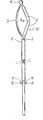
- the sampling device consists of a rod 1 of suitable length, one of the ends of which ends in a scraper device 10. This rod 1 slides in a tube 2.
- the scraper device 10 consists of two strips 3 joined by a narrow part 3a deformable in an elastic manner, forming a hinge; the lamellae 3 form an obtuse angle therebetween, one of the lamellae 3 is connected to the rod 2 and the other to a sphere - or ball - 4.
- This sphere 4 and the blade 3 at the bottom are joined by a rod 5 in the form of an arc of a circle which subtends the arc formed by the lamellae 3; the rod 5 turns its convexity on the side opposite to the lamellae 3; the length of the rod 5 is preferably slightly less than that of the two strips 3 placed end to end which form the actual scraper element 10.
- two tongues 6 arranged on each side, allow the passage of the tube 2 (for mounting the device) by folding into a housing 11 provided for this purpose in the rod 1. These tongues 6 subsequently form a stop limiting the sliding of the rod 1 in this tube 2.
- the entire gripping device 3,4,5,10 enters the tube up to the the ball 4 comes into abutment against the end of the tube 2, this ball having a larger diameter than that of the tube 2.
- the reverse maneuver is then practiced and allows spreading of the sample on a microscope slide for examination.
- the device which has just been described can be manufactured by plastic molding; the elements 1, 3, 4, 5, 10 are advantageously molded in one piece. This device allows, by its design, clean and precise samples on a large surface and without trauma during this work.
Abstract
Description
La présente invention concerne un dispositif pour prélèvements d'endomètre composé d'au moins un élément racleur de forme allongée comprenant au moins une lamelle, cet élément racleur étant fixé en bout d'une tige coulissant dans un tube à l'intérieur duquel ledit élément racleur peut être introduit par tirage de la tige dans le tube.The present invention relates to a device for endometrial samples composed of at least one scraper element of elongated shape comprising at least one strip, this scraper element being fixed at the end of a rod sliding in a tube inside which said element scraper can be inserted by pulling the rod into the tube.
Dans ce dispositif on réintroduit l'élément racleur dans le tube, après usage, en tirant sur la tige afin de sortir le dispositif sans souiller le prélèvement.In this device, the scraper element is reintroduced into the tube, after use, by pulling on the rod in order to remove the device without contaminating the sample.
Dans des dispositifs connus de ce type (brevets américains 3,635,222 et 3,491,747), l'élément racleur comporte des dents qui, lorsque ledit élément racleur est réintroduit dans le tube,raclent la paroi de laquelle un endomètre doit être prélevé.In known devices of this type (American patents 3,635,222 and 3,491,747), the scraper element comprises teeth which, when said scraper element is reintroduced into the tube, scrape the wall from which an endometrium must be removed.
Dans ces dispositifs connus, les dents fléchissent durant l'opération de prélèvement et, de ce fait, elles raclent mal la paroi sur laquelle doit être fait le prélèvement, de sorte que l'on n'obtient pas de prélèvement important.In these known devices, the teeth flex during the sampling operation and, as a result, they scrape the wall badly on which the sample must be taken, so that a large sample is not obtained.
Le dispositif selon l'invention remédie à cet inconvénient et a notamment pour but de proposer un dispositif permettant un prélèvement plus important sans risque de blessure de la paroi.The device according to the invention overcomes this drawback and in particular has the aim of proposing a device allowing a greater removal without risk of injury to the wall.
Ce but est atteint, conformément à l'invention, du fait que ledit élément racleur est de forme arquée, et il est sous-tendu "par un jonc arqué dont le côté convexe est tourné du côté opposé à l'élément racleur, moyennant quoi, lorsque ledit élément racleur muni du jonc est introduit dans une cavité d'un être biologique et que la tige est pivotée autour de son axe, l'élément racleur subit une torsion sensiblement hélicoïdale.This object is achieved, according to the invention, because said scraper element is of arcuate shape, and it is subtended "by an arcuate rod whose convex side is turned on the side opposite to the scraper element, whereby , when said scraper element provided with the rod is introduced into a cavity of a biological being and that the rod is pivoted about its axis, the scraper element undergoes a substantially helical twist.
Avantageusement, la longueur du jonc est inférieure à celle de l'élément racleur.Advantageously, the length of the rod is less than that of the scraper element.
Avantageusement, l'élément racleur est consti= tué de plusieurs lamelles liées bout à bout qui, sous l'effet du jonc sous-tendant l'élément racleur, forment chacune, avec une lamelle voisine, un angle obtus.Advantageously, the scraper element is consti = killed by several strips linked end to end which, under the effect of the rod underlying the scraper element, each form, with a neighboring strip, an obtuse angle.
Avantageusement, les lamelles voisines sont liées entre-elles par une partie étroite déformable de façon élastique.Advantageously, the neighboring lamellae are linked together by a narrow part which is elastically deformable.
Avantageusement, l'extrémité de l'élément racleur comporte une sphère de diamètre supérieur à celui du tube afin de former butée d'arrêt lors de la rentrée de cet élément racleur dans le tube.Advantageously, the end of the scraper element has a sphere of diameter greater than that of the tube in order to form a stopper when this scraper element reenters the tube.
Avantageusement, le bout de la tige opposé à l'élément racleur et qui est extérieur au tube,comporte au moins une languette qui forme butée d'arrêt pour le coulissement de la tige dans le tube afin d'être sûr qu'en butée, l'élément racleur est sorti du tube, cette languette s'aplatissant contre la tige lorsqu'on introduit celle-ci dans le tube.Advantageously, the end of the rod opposite the scraper element and which is external to the tube, comprises at least one tongue which forms a stop stop for the sliding of the rod in the tube in order to be sure that when it stops, the scraper element is taken out of the tube, this tongue flattening against the rod when the latter is introduced into the tube.
Avantageusement, l'élément racleur, le jonc et la tige et, le cas échéant, la sphère et la languette de butée, forment ensemble une seule pièce moulée en matière plastique.Advantageously, the scraper element, the rod and the rod and, where appropriate, the sphere and the stop tab, together form a single molded plastic part.
Les caractéristiques et avantages de l'invention seront mieux compris à la lecture de la description qui va suivre d'un exemple de réalisation et en se référant au dessin annexé sur lequel :
- - la figure unique est une vue en élévation d'un dispositif selon l'invention.
- - The single figure is an elevational view of a device according to the invention.
Le dispositif de prélèvement selon l'invention est constitué par une tige 1 de longueur appropriée dont une des extrémités se termine par un dispositif racleur 10. Cette tige 1 coulisse dans un tube 2.The sampling device according to the invention consists of a
Le dispositif racleur 10 est constitué par deux lamelles 3 réunies par une partie étroite 3a déformable de façon élastique, formant charnière ; les lamelles 3 forment un angle obtus entre-elles, l'une des lamelles 3 est reliée à la tige 2 et l'autre à une sphé- re - ou boule - 4. Cette sphère 4 et la lame 3 du bas sont réunies par un jonc 5 en forme d'arc de cercle qui soustend l'arc formé par les lamelles 3 ; le jonc 5 tourne sa convexité du côté opposé aux lamelles 3 ; la longueur du jonc 5 est, de préférence, légèrement inférieure à celle des deux lamelles 3 mises bout à bout qui forment l'élément racleur proprement dit 10.The
A l'autre extrémité de la tige 2, deux languettes 6 disposées de chaque côté, permettent le passage du tube 2 (pour le montage du dispositif) en se rabattant dans un logement 11 prévu à cet effet dans la tige 1. Ces languettes 6 forment, par la suite, butée limitant le coulissement de la tige 1 dans ce tube 2.At the other end of the
Pour l'utilisation du dispositif, l'on tient le tube 2 et l'on tire vers le bas de la tige 1, l'ensemble du dispositif de prise 3,4,5,10 pénètre dans le tube jusqu'à l'entrée en butée de la boule 4 contre le bout du tube 2, cette boule présentant un diamètre plus fort que celui du tube 2.To use the device, hold the
Il est ensuite aisé d'introduire le dispositif dans la cavité de l'être biologique sans recueillir au passage des éléments étrangers au prélèvement souhaité.It is then easy to introduce the device into the cavity of the biological being without collecting in the passage of elements foreign to the desired sample.
Lorsque le dispositif est en place, en repoussant la tige 1 dans le tube 2, le dispositif de prise 3,4,5,10 ressort et reprend sa forme initiale, les butées 6 empêchant un coulissement excessif de la tige 1 dans le tube 2. En tournant la tige autour de son axe longitudinal dans le tube 2, un mouvement de rotation est imprimé au dispositif de prise et les lamelles 3, sous la pression due a l'appui de l'arc de cercle 5, peuvent ainsi racler et prélever la muqueuse à examiner. Cette combinaison d'appui et de rotation, amène une torsion du dispositif de prise, obligeant les lamelles 3 à prendre une position hélicoïdale sous un certain angle procurant un prélèvement plus important, sans risque de blessure , causes de saignements qui rendent la lecture ultérieure du prélèvement difficile.When the device is in place, by pushing the
Après cette rotation, il suffit de rentrer le dispositif de prise dans le tube 2 en tirant la tige 1 jusqu'à l'entrée en butée de la boule 4, le prélèvement raclé se trouve alors protégé contre les contaminations inévitables, lors du retrait du lieu de prélèvement.After this rotation, it suffices to re-enter the gripping device in the
La manoeuvre inverse est pratiquée ensuite et permet l'étalement du prélèvement sur une lame de microscope pour examen.The reverse maneuver is then practiced and allows spreading of the sample on a microscope slide for examination.
Le dispositif qui vient d'être décrit peut être fabriqué par moulage en matière plastique ; les éléments 1,3,4,5,10 sont avantageusement moulés en une seule pièce. Ce dispositif permet, par sa conception, des prélèvements propres et précis sur une surface importante et sans traumatisme lors de ce travail.The device which has just been described can be manufactured by plastic molding; the
Bien entendu diverses modifications peuvent être apportées par l'homme de l'art au dispositif qui vient d'être décrit uniquement à titre d'exemple, non limitatif, sans sortir du cadre de l'invention, en particulier on peut remplacer les deux lamelles 3 par une seule lamelle arquée sous-tendue par le jonc 5.Of course various modifications can be made by those skilled in the art to the device which has just been described by way of example only, without limitation, without departing from the scope of the invention, in particular the two strips can be replaced. 3 by a single arcuate strip subtended by the
Claims (7)
ledit élément racleur (10) est de forme arquée, et il est sous-tendu par un jonc arqué (5) dont le côté convexe est tourné du côté opposé à l'élément racleur, moyennant quoi, lorsque ledit élément racleur (10) muni du jonc (5) est introduit dans une cavité d'un être biologique et que la tige (1) est pivotée autour de son axe, l'élément racleur (10) subit une torsion sensiblement hélicoidale.1. Device for endometrial sampling, composed of at least one scraper element (10) of elongated shape comprising at least one strip (3), this scraper element being fixed at the end of a rod (1) sliding in a tube (2) inside which said scraper element can be introduced by pulling the rod into the tube, characterized in that
said scraper element (10) is of arcuate shape, and it is subtended by an arched rod (5) whose convex side is turned on the side opposite to the scraper element, whereby when said scraper element (10) provided rod (5) is introduced into a cavity of a biological being and as the rod (1) is pivoted about its axis, the scraper element (10) undergoes a substantially helical twist.
Priority Applications (1)
| Application Number | Priority Date | Filing Date | Title |
|---|---|---|---|
| AT80400105T ATE5937T1 (en) | 1979-01-24 | 1980-01-23 | DEVICE FOR TAKING ENDOMETRIC TISSUE SAMPLES. |
Applications Claiming Priority (2)
| Application Number | Priority Date | Filing Date | Title |
|---|---|---|---|
| FR7901832 | 1979-01-24 | ||
| FR7901832A FR2447177A1 (en) | 1979-01-24 | 1979-01-24 | DEVICE FOR ENDOMETER SAMPLING |
Publications (3)
| Publication Number | Publication Date |
|---|---|
| EP0014150A2 true EP0014150A2 (en) | 1980-08-06 |
| EP0014150A3 EP0014150A3 (en) | 1980-08-20 |
| EP0014150B1 EP0014150B1 (en) | 1984-01-25 |
Family
ID=9221170
Family Applications (1)
| Application Number | Title | Priority Date | Filing Date |
|---|---|---|---|
| EP80400105A Expired EP0014150B1 (en) | 1979-01-24 | 1980-01-23 | Cervical biopsy sampling instrument |
Country Status (12)
| Country | Link |
|---|---|
| US (1) | US4338952A (en) |
| EP (1) | EP0014150B1 (en) |
| JP (1) | JPS5599243A (en) |
| AT (1) | ATE5937T1 (en) |
| AU (1) | AU532652B2 (en) |
| BR (1) | BR8000397A (en) |
| CA (1) | CA1132874A (en) |
| DE (1) | DE3066221D1 (en) |
| ES (1) | ES254328Y (en) |
| FR (1) | FR2447177A1 (en) |
| IE (1) | IE49065B1 (en) |
| MX (1) | MX149556A (en) |
Cited By (5)
| Publication number | Priority date | Publication date | Assignee | Title |
|---|---|---|---|---|
| FR2602414A1 (en) * | 1986-08-08 | 1988-02-12 | Cornier Edgard | Device for medical sampling, in particular of mucus and secretions |
| FR2615094A1 (en) * | 1987-05-15 | 1988-11-18 | Syntex Inc | DEVICE FOR COLLECTING A BIOLOGICAL MATERIAL |
| EP0363196A1 (en) * | 1988-10-06 | 1990-04-11 | Minnesota Mining And Manufacturing Company | Tissue or mucus sampling device |
| DE3990006C1 (en) * | 1988-01-11 | 1992-05-21 | Anne Co | Cell sampling scraper - has flexible loop-like chafing section with blade and handle inserted slidably and rotatably into extension tube connected to loop |
| FR2685190A1 (en) * | 1991-12-23 | 1993-06-25 | Lefebvre Jean Marie | ROTARY ATHERECTOMY OR THROMBECTOMY DEVICE HAVING TRANSVERSAL CENTRIFUGAL DEVELOPMENT. |
Families Citing this family (13)
| Publication number | Priority date | Publication date | Assignee | Title |
|---|---|---|---|---|
| JPS5873208U (en) * | 1981-11-12 | 1983-05-18 | 日本オルガノン株式会社 | Endometrial cell collection device |
| SE8201017L (en) * | 1982-02-18 | 1983-08-19 | Odd Knudsen | INSTRUMENTS FOR SAMPLING FROM UTERUS OF MAMMALS |
| US4491132A (en) * | 1982-08-06 | 1985-01-01 | Zimmer, Inc. | Sheath and retractable surgical tool combination |
| AT381016B (en) * | 1982-09-10 | 1986-08-11 | Huber Johannes Dr | DEVICE FOR TAKING SMOOTHS FROM BODY CAVES |
| US4627444A (en) * | 1985-06-20 | 1986-12-09 | Regents Of The University Of Minnesota | Device for sampling tissues and fluids from bodily cavities |
| JPS6437498U (en) * | 1987-08-31 | 1989-03-07 | ||
| FR2640054B1 (en) * | 1988-12-07 | 1992-12-31 | Informatek Ste Nouvelle | SYSTEM FOR SETTING UP A COLLIMATOR IN A GAMMA CAMERA |
| US5624381A (en) * | 1994-08-09 | 1997-04-29 | Kieturakis; Maciej J. | Surgical instrument and method for retraction of an anatomic structure defining an interior lumen |
| US5794626A (en) * | 1994-08-18 | 1998-08-18 | Kieturakis; Maciej J. | Excisional stereotactic apparatus |
| US5555892A (en) * | 1994-11-14 | 1996-09-17 | Tipton; Clyde C. | Biopsy shaver |
| US6053876A (en) * | 1999-06-09 | 2000-04-25 | Fisher; John | Apparatus and method for marking non-palpable lesions |
| AU8485701A (en) * | 2000-08-11 | 2002-02-25 | Sdgi Holdings Inc | Surgical instrumentation and method for treatment of the spine |
| US20050197665A1 (en) * | 2004-03-08 | 2005-09-08 | Teed Ralph A. | Tongue cleaners |
Citations (2)
| Publication number | Priority date | Publication date | Assignee | Title |
|---|---|---|---|---|
| US3491747A (en) * | 1966-08-12 | 1970-01-27 | Ralph R Robinson | Curette device |
| US3635222A (en) * | 1970-07-31 | 1972-01-18 | Ralph R Robinson | Angular curette |
Family Cites Families (8)
| Publication number | Priority date | Publication date | Assignee | Title |
|---|---|---|---|---|
| US618521A (en) * | 1899-01-31 | Uterine curette | ||
| US687112A (en) * | 1900-10-04 | 1901-11-19 | Martin D Wood | Uterine curette. |
| US928011A (en) * | 1908-12-31 | 1909-07-13 | William A Whitlock | Surgical instrument. |
| US1092914A (en) * | 1913-04-07 | 1914-04-14 | Ambrose W Jones | Curette. |
| US3472230A (en) * | 1966-12-19 | 1969-10-14 | Fogarty T J | Umbrella catheter |
| US3502082A (en) * | 1967-07-10 | 1970-03-24 | Helen E Chatfield | Curette with disposable band loop blade |
| US3670732A (en) * | 1970-05-11 | 1972-06-20 | Ralph R Robinson | Vacuum curette |
| US3800781A (en) * | 1972-05-30 | 1974-04-02 | K Zalucki | Specimen-taking device |
-
1979
- 1979-01-24 FR FR7901832A patent/FR2447177A1/en active Granted
-
1980
- 1980-01-17 MX MX180833A patent/MX149556A/en unknown
- 1980-01-18 US US06/113,254 patent/US4338952A/en not_active Expired - Lifetime
- 1980-01-18 IE IE104/80A patent/IE49065B1/en unknown
- 1980-01-22 ES ES1980254328U patent/ES254328Y/en not_active Expired
- 1980-01-22 BR BR8000397A patent/BR8000397A/en unknown
- 1980-01-23 JP JP673880A patent/JPS5599243A/en active Pending
- 1980-01-23 EP EP80400105A patent/EP0014150B1/en not_active Expired
- 1980-01-23 DE DE8080400105T patent/DE3066221D1/en not_active Expired
- 1980-01-23 CA CA344,258A patent/CA1132874A/en not_active Expired
- 1980-01-23 AT AT80400105T patent/ATE5937T1/en not_active IP Right Cessation
- 1980-01-23 AU AU54870/80A patent/AU532652B2/en not_active Ceased
Patent Citations (2)
| Publication number | Priority date | Publication date | Assignee | Title |
|---|---|---|---|---|
| US3491747A (en) * | 1966-08-12 | 1970-01-27 | Ralph R Robinson | Curette device |
| US3635222A (en) * | 1970-07-31 | 1972-01-18 | Ralph R Robinson | Angular curette |
Cited By (6)
| Publication number | Priority date | Publication date | Assignee | Title |
|---|---|---|---|---|
| FR2602414A1 (en) * | 1986-08-08 | 1988-02-12 | Cornier Edgard | Device for medical sampling, in particular of mucus and secretions |
| FR2615094A1 (en) * | 1987-05-15 | 1988-11-18 | Syntex Inc | DEVICE FOR COLLECTING A BIOLOGICAL MATERIAL |
| DE3990006C1 (en) * | 1988-01-11 | 1992-05-21 | Anne Co | Cell sampling scraper - has flexible loop-like chafing section with blade and handle inserted slidably and rotatably into extension tube connected to loop |
| EP0363196A1 (en) * | 1988-10-06 | 1990-04-11 | Minnesota Mining And Manufacturing Company | Tissue or mucus sampling device |
| FR2685190A1 (en) * | 1991-12-23 | 1993-06-25 | Lefebvre Jean Marie | ROTARY ATHERECTOMY OR THROMBECTOMY DEVICE HAVING TRANSVERSAL CENTRIFUGAL DEVELOPMENT. |
| EP0549458A1 (en) * | 1991-12-23 | 1993-06-30 | LEFEBVRE, Jean-Marie | Rotating instrument for atherectomy or thrombectomy |
Also Published As
| Publication number | Publication date |
|---|---|
| FR2447177B1 (en) | 1982-06-18 |
| ES254328U (en) | 1981-03-16 |
| FR2447177A1 (en) | 1980-08-22 |
| IE49065B1 (en) | 1985-07-24 |
| EP0014150A3 (en) | 1980-08-20 |
| MX149556A (en) | 1983-11-23 |
| AU532652B2 (en) | 1983-10-06 |
| US4338952A (en) | 1982-07-13 |
| AU5487080A (en) | 1980-07-31 |
| ATE5937T1 (en) | 1984-02-15 |
| DE3066221D1 (en) | 1984-03-01 |
| ES254328Y (en) | 1981-10-01 |
| JPS5599243A (en) | 1980-07-29 |
| BR8000397A (en) | 1980-10-14 |
| CA1132874A (en) | 1982-10-05 |
| EP0014150B1 (en) | 1984-01-25 |
| IE800104L (en) | 1980-07-24 |
Similar Documents
| Publication | Publication Date | Title |
|---|---|---|
| EP0014150B1 (en) | Cervical biopsy sampling instrument | |
| EP0805652B1 (en) | Device for collecting endometrial fragments | |
| EP0065054B1 (en) | Biopsy forceps | |
| FR2480111A1 (en) | INSTRUMENT FOR RECOVERING FOLDED WIRES FROM INTRA-UTERINE CONTRACEPTIVE DEVICES | |
| FR2751199A1 (en) | PINCHING DEVICE, PARTICULARLY OF THE BIOPSY PLIER TYPE | |
| FR2775181A1 (en) | VAGINAL SPECULUM | |
| FR2470662A1 (en) | KNIFE WITH INTERCHANGEABLE BLADE | |
| FR2526304A1 (en) | TRAINING TOOLS, ESPECIALLY FOR SCREWING PIVOTS INTO TEETH | |
| FR2760633A1 (en) | STICK-HAND CURETTING INSTRUMENT | |
| FR2855746A1 (en) | Intraocular lens capsule part cutting device for cataract surgery, has circular wire with cutting edge and rolled in guide tube during its insertion into eye and unrolled to be applied on capsule to repeatedly perform cutting operation | |
| CH653880A5 (en) | Instrument for taking samples of mucus from the female genital organs | |
| CH714259B1 (en) | Tick-pulling instrument for a multifunctional pocket knife. | |
| FR2814930A1 (en) | Tool for assisting e.g. handicapped people to put on socks comprises handle with horseshoe-shaped stirrup on its end which has cylindrical wall mounted underneath with horizontal ledge across it which tapers towards ends of horseshoe arms | |
| FR2681228A1 (en) | Comb which can be adapted without adjustment to the diameter of the hair in order to remove lice, nits, dandruff and other foreign bodies from the hair | |
| CH604677A5 (en) | Double pointed plastics toothpick | |
| FR2883147A1 (en) | Multidirectional support device for feeding bottle holder, has deformable tubular unit made by helical rolling of band that is housed in flexible sheath, and clip and jaw with plastic part engaging respective ends of unit and sheath | |
| FR2610507A1 (en) | Single-use vaginal speculum | |
| EP0460543B1 (en) | Bending device for root canal dental tools | |
| FR2468539A1 (en) | PLASTIC TAPE WINDING SUPPORT | |
| BE1007545A3 (en) | Vein stripping system | |
| FR2778839A1 (en) | Biopsy clamp with opening/closing jaws on end of support | |
| FR2820678A1 (en) | INTERCHANGEABLE BLADE SCISSORS | |
| FR2462144A1 (en) | Gynaecological examination and tissue sampling instrument - comprises spatula holder, illuminating head angularly spaced from light and pair of jaws gripping sampling instrument | |
| CH507693A (en) | Egg cup | |
| FR2466242A1 (en) | Instrument for removal of intra=uterine device - is tube inserted into cervix with oval- cross=section passage extending through it and slit for passage of cord |
Legal Events
| Date | Code | Title | Description |
|---|---|---|---|
| PUAI | Public reference made under article 153(3) epc to a published international application that has entered the european phase |
Free format text: ORIGINAL CODE: 0009012 |
|
| PUAL | Search report despatched |
Free format text: ORIGINAL CODE: 0009013 |
|
| AK | Designated contracting states |
Designated state(s): AT BE CH DE GB IT NL SE |
|
| AK | Designated contracting states |
Designated state(s): AT BE CH DE GB IT NL SE |
|
| 17P | Request for examination filed |
Effective date: 19810217 |
|
| ITF | It: translation for a ep patent filed |
Owner name: JACOBACCI & PERANI S.P.A. |
|
| GRAA | (expected) grant |
Free format text: ORIGINAL CODE: 0009210 |
|
| AK | Designated contracting states |
Designated state(s): AT BE CH DE GB IT NL SE |
|
| REF | Corresponds to: |
Ref document number: 5937 Country of ref document: AT Date of ref document: 19840215 Kind code of ref document: T |
|
| REF | Corresponds to: |
Ref document number: 3066221 Country of ref document: DE Date of ref document: 19840301 |
|
| PLBE | No opposition filed within time limit |
Free format text: ORIGINAL CODE: 0009261 |
|
| STAA | Information on the status of an ep patent application or granted ep patent |
Free format text: STATUS: NO OPPOSITION FILED WITHIN TIME LIMIT |
|
| PGFP | Annual fee paid to national office [announced via postgrant information from national office to epo] |
Ref country code: DE Payment date: 19850112 Year of fee payment: 6 |
|
| 26N | No opposition filed | ||
| PGFP | Annual fee paid to national office [announced via postgrant information from national office to epo] |
Ref country code: AT Payment date: 19851219 Year of fee payment: 7 |
|
| PGFP | Annual fee paid to national office [announced via postgrant information from national office to epo] |
Ref country code: NL Payment date: 19860131 Year of fee payment: 7 |
|
| PG25 | Lapsed in a contracting state [announced via postgrant information from national office to epo] |
Ref country code: AT Effective date: 19870123 |
|
| PG25 | Lapsed in a contracting state [announced via postgrant information from national office to epo] |
Ref country code: SE Effective date: 19870124 |
|
| PG25 | Lapsed in a contracting state [announced via postgrant information from national office to epo] |
Ref country code: CH Effective date: 19870131 |
|
| BERE | Be: lapsed |
Owner name: ARTS ET TECHNIQUES NOUVELLES Effective date: 19870131 |
|
| PG25 | Lapsed in a contracting state [announced via postgrant information from national office to epo] |
Ref country code: NL Effective date: 19870801 |
|
| GBPC | Gb: european patent ceased through non-payment of renewal fee | ||
| NLV4 | Nl: lapsed or anulled due to non-payment of the annual fee | ||
| REG | Reference to a national code |
Ref country code: CH Ref legal event code: PL |
|
| PG25 | Lapsed in a contracting state [announced via postgrant information from national office to epo] |
Ref country code: DE Effective date: 19871001 |
|
| PG25 | Lapsed in a contracting state [announced via postgrant information from national office to epo] |
Ref country code: GB Effective date: 19881118 |
|
| PG25 | Lapsed in a contracting state [announced via postgrant information from national office to epo] |
Ref country code: BE Effective date: 19890131 |
|
| EUG | Se: european patent has lapsed |
Ref document number: 80400105.5 Effective date: 19870923 |