EP0014663A1 - Process and apparatus for controlling the radiation flux through a transparent wall, and application of the said process - Google Patents
Process and apparatus for controlling the radiation flux through a transparent wall, and application of the said process Download PDFInfo
- Publication number
- EP0014663A1 EP0014663A1 EP80400195A EP80400195A EP0014663A1 EP 0014663 A1 EP0014663 A1 EP 0014663A1 EP 80400195 A EP80400195 A EP 80400195A EP 80400195 A EP80400195 A EP 80400195A EP 0014663 A1 EP0014663 A1 EP 0014663A1
- Authority
- EP
- European Patent Office
- Prior art keywords
- transparent
- fluid
- liquid
- emulsion
- opacifying
- Prior art date
- Legal status (The legal status is an assumption and is not a legal conclusion. Google has not performed a legal analysis and makes no representation as to the accuracy of the status listed.)
- Withdrawn
Links
Images

Classifications
-
- G—PHYSICS
- G05—CONTROLLING; REGULATING
- G05D—SYSTEMS FOR CONTROLLING OR REGULATING NON-ELECTRIC VARIABLES
- G05D23/00—Control of temperature
- G05D23/01—Control of temperature without auxiliary power
-
- A—HUMAN NECESSITIES
- A01—AGRICULTURE; FORESTRY; ANIMAL HUSBANDRY; HUNTING; TRAPPING; FISHING
- A01G—HORTICULTURE; CULTIVATION OF VEGETABLES, FLOWERS, RICE, FRUIT, VINES, HOPS OR SEAWEED; FORESTRY; WATERING
- A01G9/00—Cultivation in receptacles, forcing-frames or greenhouses; Edging for beds, lawn or the like
- A01G9/24—Devices or systems for heating, ventilating, regulating temperature, illuminating, or watering, in greenhouses, forcing-frames, or the like
- A01G9/243—Collecting solar energy
-
- F—MECHANICAL ENGINEERING; LIGHTING; HEATING; WEAPONS; BLASTING
- F24—HEATING; RANGES; VENTILATING
- F24S—SOLAR HEAT COLLECTORS; SOLAR HEAT SYSTEMS
- F24S50/00—Arrangements for controlling solar heat collectors
- F24S50/80—Arrangements for controlling solar heat collectors for controlling collection or absorption of solar radiation
-
- Y—GENERAL TAGGING OF NEW TECHNOLOGICAL DEVELOPMENTS; GENERAL TAGGING OF CROSS-SECTIONAL TECHNOLOGIES SPANNING OVER SEVERAL SECTIONS OF THE IPC; TECHNICAL SUBJECTS COVERED BY FORMER USPC CROSS-REFERENCE ART COLLECTIONS [XRACs] AND DIGESTS
- Y02—TECHNOLOGIES OR APPLICATIONS FOR MITIGATION OR ADAPTATION AGAINST CLIMATE CHANGE
- Y02A—TECHNOLOGIES FOR ADAPTATION TO CLIMATE CHANGE
- Y02A40/00—Adaptation technologies in agriculture, forestry, livestock or agroalimentary production
- Y02A40/10—Adaptation technologies in agriculture, forestry, livestock or agroalimentary production in agriculture
- Y02A40/25—Greenhouse technology, e.g. cooling systems therefor
-
- Y—GENERAL TAGGING OF NEW TECHNOLOGICAL DEVELOPMENTS; GENERAL TAGGING OF CROSS-SECTIONAL TECHNOLOGIES SPANNING OVER SEVERAL SECTIONS OF THE IPC; TECHNICAL SUBJECTS COVERED BY FORMER USPC CROSS-REFERENCE ART COLLECTIONS [XRACs] AND DIGESTS
- Y02—TECHNOLOGIES OR APPLICATIONS FOR MITIGATION OR ADAPTATION AGAINST CLIMATE CHANGE
- Y02E—REDUCTION OF GREENHOUSE GAS [GHG] EMISSIONS, RELATED TO ENERGY GENERATION, TRANSMISSION OR DISTRIBUTION
- Y02E10/00—Energy generation through renewable energy sources
- Y02E10/40—Solar thermal energy, e.g. solar towers
-
- Y—GENERAL TAGGING OF NEW TECHNOLOGICAL DEVELOPMENTS; GENERAL TAGGING OF CROSS-SECTIONAL TECHNOLOGIES SPANNING OVER SEVERAL SECTIONS OF THE IPC; TECHNICAL SUBJECTS COVERED BY FORMER USPC CROSS-REFERENCE ART COLLECTIONS [XRACs] AND DIGESTS
- Y02—TECHNOLOGIES OR APPLICATIONS FOR MITIGATION OR ADAPTATION AGAINST CLIMATE CHANGE
- Y02P—CLIMATE CHANGE MITIGATION TECHNOLOGIES IN THE PRODUCTION OR PROCESSING OF GOODS
- Y02P60/00—Technologies relating to agriculture, livestock or agroalimentary industries
- Y02P60/12—Technologies relating to agriculture, livestock or agroalimentary industries using renewable energies, e.g. solar water pumping
Definitions
- the present invention relates to a method and a device for regulating the flux of radiation (sunlight for example ) which passes through a transparent wall, and for recovering the energy intercepted during said regulation.
- the greenhouses used up to now are usually of two types: on the one hand, envelopes made of synthetic material such as polyvinyl chloride (PVC), polyethylene, held by hoops for intensive use, in particular at market gardeners, and on the other hand glass canopies used more particularly in horticulture.
- PVC polyvinyl chloride
- These latter greenhouses generally include internal heating means, usually central heating and humidification, in order to maintain a well-determined temperature and hygrometry according to the cultivated species.
- Glasshouses of the glass type with central heating incorporated are provided with means indicating the temperature and the humidity percentage inside the enclosure; thus, a thermostat system regulates the temperature during the hours of lighting and exposure of the sun having the effect of lowering energy consumption during said hours.
- an apparatus of the type of that of this patent constitutes an energy recuperator rather than an apparatus for regulating radiation flux.
- the present invention finds an application both during hours of low sunshine and intense sunshine; it also has the advantage of being able to be implemented in conjunction with already existing installations with little or no modifications.
- the basic idea of the present invention is to obtain an adjustment of the variations of the photonic flux emitted by the sun and, consequently, of the density of the light admitted into an enclosure such as a greenhouse in a simple and effective with a relatively low cost price, adjustment which has not been obtained until now by the means of the prior art.
- the present invention provides a simple process, easy to implement, eliminating the various aforementioned drawbacks, finding a particular application, in particular for the air conditioning of greenhouses by means of a closed circuit device of a very rational and very suitable design.
- the method of the invention is based on a simple and functional principle allowing the temperature of an enclosure heated by solar energy to be adjusted at low cost by increasing or reducing the rate of absorption of the photonic flux, thereby controlling. the light energy introduced into an enclosure such as a greenhouse, and to recover said energy.
- the present invention provides a method for regulating the flux of radiation, sunlight for example, which passes through a transparent wall, and for recovering the energy intercepted during said regulation, method in which one makes circulating a fluid in a circuit comprising a passage between transparent surfaces, for example transparent tubes, or a space between two transparent walls, placed to constitute said wall traversed by the radiation, and in which a transparent liquid is circulated as heat transfer fluid loaded with an opacifying agent, the quantity of opacifying agent introduced into the liquid is acted upon to adjust the absorbency of the liquid sent into said transparent tubes or between said transparent blades and, consequently, the amount of energy absorbed or reflected .
- the transparent liquid and the opacifying agent are separated after they have passed through said tubes or between said blades, and one and / or the other of these products is recycled, in proportions corresponding to the absorbing power. or reflective desired for the fluid.
- THE opacifying product can form with the transparent liquid an emulsion with high reflecting power.
- the opacifying agent is a gas
- an emulsion of this gas is formed in the transparent liquid, and the relative proportions of gas in the liquid are changed, and / or the size of the bubbles in the emulsion in order to make vary the absorbing and / or reflecting power of the fluid.
- the transparent liquid is water and the opacifying product is a liquid immiscible with water and capable of absorbing high bant such as mineral oil, vegetable oil or tinted kerosene.
- the opacifying product consists of fine solid particles, such as polypropylene microbeads, from 1 to 400 microns.
- the energy absorbed by said fluid is recovered during its passage through said transparent tubes or between said transparent blades.
- the two tanks 1 and 2 each include a product outlet designated respectively by 4 for the transparent fluid and by 5 for the opacifying product.
- the transparent liquid leaving the outlet 4 is routed through line 6 to a pump 8.
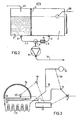
- the opacifying product is directed from outlet 5, via a line 7, to a metering or metering device 9 regulating the quantity desired according to needs, as determined by a photoresist cell 10 located outside the device and connected by any suitable means 11 (illustrated very schematically) to the metering device 9. The role and operation of said cell will be described more away in more detail.
- the opacifying product, via line 12 joins at junction 13, in line 14, the transparent immiscible fluid, and the suspension formed at a concentration determined by the photoresist cell 10 is directed by said line 14, via line 15, in the direction of the solar collector 16.
- the transparent fluid which is a heat transfer fluid with a variable amount of immiscible opacifying agent, can then, at the outlet of the pipe 15, move around the periphery of the solar collector 16 where it has a radiation modulation effect, it absorbs a certain amount of heat and then enters the circuit 17 in which it can transfer the absorbed energy, for example, to heat storage bricks symbolized by the reference B in Figure 1 or any other suitable means.
- the transparent fluid with a predetermined variable quantity of opacifying agent, rid of the energy which it has absorbed, then returns, by means of the pipe 18, towards a separator 19 constituted, for example, by a simple filtration device, (in another embodiment, the separator is constituted by a filtering wall placed between the tanks 1 and 2).
- a separator 19 constituted, for example, by a simple filtration device, (in another embodiment, the separator is constituted by a filtering wall placed between the tanks 1 and 2).
- This filtration device makes it possible to easily separate the transparent fluid emulsion-opacifying agent and each elementary constituent is reintroduced by the respective conduits 20 and 21 into the corresponding reservoirs 1 and 2.
- the device for implementing the method according to the present invention operates continuously, in a self-contained closed circuit. me, and that said operation is based on the information collected by the photoresist cell 10 placed outside the enclosure 22 such as a greenhouse.
- This cell 10 has the characteristic of being provided with an adjustment plate making it possible to determine the function of the metering device 9, the role of which is to admit into the circuit of the heat-transfer fluid a variable quantity of immiscible opacifying agent; thus, the he increase in light intensity modifies the function or position of the metering device which admits a greater opacifying agent flow rate.
- FIG. 2 represents, on a larger scale, the tank or tank assembly according to a mounting variant.
- 1 designates the transparent fluid reservoir
- 2 the reservoir with opacifying product
- 3 the separator assembly.
- the two products leave the tanks or reservoirs 1 and 2 through the respective outlets 4.5 to be introduced into the pipes 6.7; however, in this case, a filter F is provided upstream of the metering device 9, the role of which is to additionally rid, if necessary, the transparent fluid of the last traces of opacifying product before it passes through the metering device 9.
- the transparent fluid can be any suitable heat transfer fluid; however, in the use described here, it is preferred, for cost reasons, to use water which is, in general, of a lower cost price.
- the opacifying product can be liquid or solid.
- a liquid product it can be chosen from the group comprising kerosene, a mineral oil or a vegetable oil; however, it can also be solid and be in the form of fine particles.
- they may be microbeads of polypropylene or the like with a diameter included in the range of 250 to 400 microns.
- the solar collector 16 is preferably made from self-supporting multi-tubular plastic profiles, profiles which are transparent and perfectly permeable to solar radiation and which allow good circulation of the coolant. loaded or not with opacifying product.
- the fluid can also circulate between two parallel transparent surfaces constituting a flattened tube.
- circuit 17 the heat transfer fluid transfers the energy it has absorbed to any means of heat accumulation, for example bricks B illustrated diagrammatically; circuit 17 for recovering energy can be suitably protected by any coating R, shown by hatching in Figure l, of any suitable kind.
- the method according to the present invention and the devices that have just been described make it possible to dose the light energy entering an enclosure, for example a greenhouse, at will, and in this case to orient the photo phenomena in a perfectly adapted range. -synthesis.
- They can also be used to limit and / or regulate the light energy entering an enclosure or there are objects which do not tolerate excessive heat or lighting, such as certain food products. They can also be used for air conditioning in premises or workshops.
- the device essentially functions as an adjustable opacity screen, and the recovery of solar energy is only a secondary aspect that can sometimes be overlooked, the circuit 17 then being designed as a simple refrigerant intended to avoid excessive heating of the liquid.
- FIG 3 there is shown schematically an alternative embodiment of a part of the device according to the invention, variant in which there is provided, inside the enclosure 22, another cell 10 'similar to cell 10 placed outside and which is connected to a calculation unit 23, said assembly 23, also in connection with cell 10, being able to act according to the information received from one or the other cell or both on the metering device 9 in order to regulate the circulation of the fluid in the device.
- the two cells 10 and 10 ' can also be connected by any suitable means. These means are symbolized in Figure 3 by dotted lines.
- the operation of the device of the present invention makes it possible to eliminate inertia as much as possible and to follow, with as small a phase shift as possible, the variations in the photonic flux emitted by the sun and, consequently, the density of light admitted into the 'pregnant.
- the agent for moderating and regulating the photonic flux is only opacifying and, in this case, its proportion in the circuit creates a more or less large and infinitely adjustable screen.
- an opacifying agent having selective characteristics admitting inside the enclosure (greenhouse for example) only certain wavelengths of the solar spectrum.
- the device according to the invention in addition to the fact that its operation can be combined in the case of a greenhouse with the dosage of carbon dioxide and the percentage of humidity, allows, in a satisfactory manner, to regulate the luminous flux received, to capture energy and to restore it thereafter.
- a different application of the process of the invention consists not in absorbing solar radiation to protect it or to use it for heating purposes but in limiting the energy consumption used for lighting, and possibly heating Locals.
- an opacifying product which gives the fluid a strong reflecting power. This can be achieved, for example, with metallic particles or by forming an emulsion with a gas or with an immiscible liquid. The glass surfaces thus become, at night, surfaces with high reflectance.
- both the liquid and the opacifying product are recycled. If one and / or the other of these products is inexpensive and can then be rejected or recovered, the installations will be easily simplified. This will be the case, for example, for a gas-water emulsion like the one we have just mentioned. This can also be the case for example if we use as clouding products colored products, such as; liquid fuels, waste oils etc ... which are then burned or otherwise treated, after separation if necessary.
- the device comprises, in addition to the transparent tubes or blades, only the outlet pipes and the metering device with the light flow sensor which controls it.
- a pump is only necessary if the supply cannot be done by gravity or by thermosiphon.
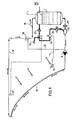
- FIG. 4 describes another device for implementing the method according to the preferred method of the invention, and in which the heat transfer fluid is an air in water emulsion.
- the same members as in Figures 1 to 3 bear the same references
- the device comprises a closed fluid circulation circuit with a closed water tank 1, a circulation pump 8, a double-walled transparent surface 16 and a return pipe 18.
- an emulsifier 30 consisting of a cylindrical tube traversed by water, inside which is placed a bicone coaxial with the tube and forming a venturi, in the axis of which opens, a pipe 31 supplying compressed air.
- the venturi is extended by a converging piece of porous sintered metal.
- the compressed air comes either from the outside or from the upper part of the tank 1 and is sent to the injector by a pump 32, with variable flow rate controlled by a photoelectric sensor 10.
- Filters 33 ensure a supply of dust-free air free of abrasive particles, and the liquid also passes through a filter 34, which ensures a long service life for the installation and in particular for transparent surfaces even if they are made of plastic.
- baffle emulsion breaker 35 On the return line 18 is interposed a baffle emulsion breaker 35.
- means are provided for sending into the circuit, in place of the emulsion, clean and dry air, so as to avoid condensation during shutdown periods. These means include an air heater 36, placed between the pump 32 and the foam concentrate 30.
- a thermometric probe 37 placed on the pipe 18, then controls, as a function of the temperature, and therefore of the vapor content of air, the distribution between the recycled air and the air collected outside.
- a valve 38 for adjusting the pressure in the circuit is placed on the line 18, upstream of the emulsion breaker 35. It makes it possible to vary the pressure, in particular in the transparent surface 16, and consequently to act on the bubbles form the emulsion; indeed, an increase in pressure. causes a reduction in the size of the bubbles by dissolution of the gas in the liquid.
- a test installation conforming to this scheme worked under the following conditions: transparent surface of 2 m 2 constituted by a multitubular polycarbonate profile comprising 200 channels of 5 x 5 mm, pump flow 8: 8 m 3 / h - pressure in the circuit: 20 m of water - volume of the tank: 50 liters.
- the speed of circulation of the fluid in the suction pipe of the pump 8 was found to be suitable between 0.3 and 1 meter per second.
- the emulsion once started, can be maintained indefinitely under the effect of turbulence and sudden pressure variations, with a slight increase in the proportion of surfactant, variable according to the size of the circuit and the speed of circulation.
- the proportion of surfactant is determined by taking as a rule that the time at the end of which the emulsion separates when it is at rest is approximately 1.5 to 5 times the time that the emulsion takes to travel the circuit.
- the basic idea of the present invention is to act on the quantity or the form of the opacifying agent to modify the absorption or regulation properties of fluids.
- Hydrophobic membranes can be used in particular in perforated and treated plastic sheet, which are commercially available.
- the applications of the method according to the invention are not limited to what has been described above; it can also be used to prevent condensation on transparent surfaces, and even make them play a role of radiator. It can also be used to color or conceal certain surfaces for aesthetic, privacy, or security purposes.
Abstract
Description
La présente invention concerne un procédé et un dispositif de régulation du flux de rayonnement, lumière solaire par exemple)qui traverse une paroi transparente,et de récupération de l'énergie interceptée au cours de ladite régulation.The present invention relates to a method and a device for regulating the flux of radiation (sunlight for example ) which passes through a transparent wall, and for recovering the energy intercepted during said regulation.
Les serres utilisées jusqu'à présent sont habituellement de deux types :on connaît d'une part les enveloppes en matière synthétique telles qu'en poly - chlorure de vinyle (PVC),en polyéthylène,maintenues par des arceaux à usage intensif,notamment chez les maraîchers, et d'autre part les serres à verrière utilisées plus particulièrement en horticulture. Ces dernières serres comportent,en général,des moyens internes de chauffage,habituellement un chauffage central et d'humidification,afin de maintenir une température et une hygrométrie bien déterminées selon les espèces cultivées.The greenhouses used up to now are usually of two types: on the one hand, envelopes made of synthetic material such as polyvinyl chloride (PVC), polyethylene, held by hoops for intensive use, in particular at market gardeners, and on the other hand glass canopies used more particularly in horticulture. These latter greenhouses generally include internal heating means, usually central heating and humidification, in order to maintain a well-determined temperature and hygrometry according to the cultivated species.
Au moyen des enveloppes en matière synthétique,il n'est pas possible de réguler la température à l'intérieur de l'enceinte;en effet,leur rôle se limite à la protection contre le froid,de préférence vis-à-vis des premières gelées et, lors de l'exposition aux rayonnements solaires,lesdites enveloppes sont découvertes puis installées à nouveau en fonction de la baisse d'exposition. Il s'agit là de moyens assez peu élaborés,prenant du temps,nécessitant de nombreuses manipulations et finalement peu pratiques.It is not possible to regulate the temperature using plastic envelopes inside the enclosure; in fact, their role is limited to protection against the cold, preferably with regard to the first frosts and, during exposure to solar radiation, said envelopes are discovered and then installed again depending on the drop in exposure. These are fairly underdeveloped means, taking time, requiring many manipulations and ultimately impractical.
Les serres du type verrière à chauffage central incorporé sont munies de moyens indicateurs de la température et du pourcentage d'humidité à l'intérieur de l'enceinte;ainsi,un système à thermostat régule la température pendant les heures d'éclairement et d'exposition du soleil ayant pour effet de baisser la consommation d'énergie pendant lesdites heures.Glasshouses of the glass type with central heating incorporated are provided with means indicating the temperature and the humidity percentage inside the enclosure; thus, a thermostat system regulates the temperature during the hours of lighting and exposure of the sun having the effect of lowering energy consumption during said hours.
Cependant,il existe un problème avec ce type de serres à verrière:pendant les heures chaudes d'une journée où l'intensité lumineuse réfléchie sur la serre peut provoquer des phénomènes de surchauffe'ou de sur-exposition ne convenant pas aux espèces cultivées.However, there is a problem with this type of glasshouse: during the hot hours of a day when the light intensity reflected on the greenhouse can cause overheating or over-exposure phenomena not suitable for cultivated species.
Pour remédier à ce problème,on a utilisé divers moyens tels que des bâches de couverture,des volets tant internes qu'externes,mais ces moyens,outre qu'ils ne permettent pas de récupérer l'énergie solaire, ne procurent pas, de plus,un réglage précis et satisfaisant de la régulation de la température à l'intérieur de l'enceinte .To remedy this problem, various means have been used such as covering tarpaulins, both internal and external shutters, but these means, besides not making it possible to recover solar energy, also do not provide , a precise and satisfactory adjustment of the temperature regulation inside the enclosure.
On a également proposé , par exemple dans le brevet US 3 107 052 de prévoir une serre dont la paroi transparente est creuse,et de faire circuler un liquide capable d'absorber une partie du rayonnement dans l'épaisseur de la paroi. Ce liquide s'échauffe sous l'effet du rayonnement et la chaleur qu'il a reçue peut être soit stockée soit dissipée selon les besoins,de façon à maintenir la température du liquide dans des limites choisies à l'avance. On peut utiliser selon les besoins des liquides qui diffèrent entre eux par leurs pro- priétés d'absorbtion ou par leur couleur,ou encore y introduire des bulles de gaz,des paillettes métalliques, des particules colorées à des fins ornementales. Un tel système permet difficilement une adaptation à des; variations rapides des conditions de rayonnement en effet les propriétés absorbantes ou réfléchissantes d'un liquide dépendent peu de la température,si bien qu'une brusque variation de l'ensoleillement,par exemple, ne sera compensée qu'après un temps assez considérable, en raison de l'inertie des moyens de stockage d'énergie. Ainsi,un appareil du genre de celui de ce brevet constitue un récupérateur d'énergie plutôt qu'un appareil de régulation de flux de rayonnement.It has also been proposed, for example in US Pat. No. 3,107,052 to provide a greenhouse whose transparent wall is hollow, and to circulate a liquid capable of absorbing part of the radiation in the thickness of the wall. This liquid heats up under the effect of radiation and the heat which it has received can either be stored or dissipated as required, so as to maintain the temperature of the liquid within limits chosen in advance. Can be used as appropriate liquids which differ from each other by their pro- p r i é sides of absorption or color, or introduce gas bubbles, metal flakes, colored particles for ornamental purposes. Such a system hardly allows adaptation to; rapid variations in radiation conditions in fact the absorbent or reflective properties of a liquid depend little on temperature, so that a sudden variation in sunshine, for example, will not be compensated for until after a fairly considerable time, because of the inertia of the energy storage means. Thus, an apparatus of the type of that of this patent constitutes an energy recuperator rather than an apparatus for regulating radiation flux.
On peut faire la même remarque à propos d'autres dispositifs analogues,par exemple ceux des demandes de brevet FR 2.271 763, FR 2.344.217 et DE 2 608 302.The same remark can be made with regard to other similar devices, for example those of patent applications FR 2,271,763, FR 2,344,217 and DE 2,608,302.
La présente invention trouve une application à la fois pendant les heures à faible ensoleillement et à ensoleillement intense;elle présente en outre l'avantage de pouvoir être mise en oeuvre en liaison avec les installations déjà existantes avec peu ou pas de modifications.The present invention finds an application both during hours of low sunshine and intense sunshine; it also has the advantage of being able to be implemented in conjunction with already existing installations with little or no modifications.
L'idée de base de la présente invention est d'obtenir un réglage des variations du flux photonique émis par le soleil et, par conséquent,de la densité de la lumière admise dans une enceinte telle qu'une serre d'une façon simple et efficace avec un prix de revient relativement bas,réglage qui n'a pu être obtenu jusqu'à présent par les moyens de la technique antérieure.The basic idea of the present invention is to obtain an adjustment of the variations of the photonic flux emitted by the sun and, consequently, of the density of the light admitted into an enclosure such as a greenhouse in a simple and effective with a relatively low cost price, adjustment which has not been obtained until now by the means of the prior art.
Il est connu que certaines alternances et dégradés éclairement-obscurité sont absolument nécessaires à la modification,par exemple,de périodes de floraison.It is known that certain alternations and light-dark gradations are absolutely necessary for the modification, for example, of flowering periods.
La présente invention propose un procédé simple,facile à mettre en oeuvre,supprimant les divers inconvénients précités,trouvant une application particulière,notamment pour la climatisation de serres au moyen d'un dispositif à circuit fermé d'une conception très rationnelle et très appropriée.The present invention provides a simple process, easy to implement, eliminating the various aforementioned drawbacks, finding a particular application, in particular for the air conditioning of greenhouses by means of a closed circuit device of a very rational and very suitable design.
Le procédé de l'invention repose sur un principe simple et fonctionnel permettant de régler à faible coût la température d'une enceinte chauffée par énergie solaire en augmentant ou en réduisant le taux d'absorption du flux photonique,en contrôlant ainsi. l'énergie lumineuse introduite dans une enceinte telle qu'une serre,et de récupérer ladite énergie.The method of the invention is based on a simple and functional principle allowing the temperature of an enclosure heated by solar energy to be adjusted at low cost by increasing or reducing the rate of absorption of the photonic flux, thereby controlling. the light energy introduced into an enclosure such as a greenhouse, and to recover said energy.
Ainsi,la présente invention fournit un procédé de régulation.du flux de rayonnement,lumière solaire par exemple,qui traverse une paroi transparente, et de récupération de l'énergie interceptée au cours de ladite régulation ,procédé dans lequel on fait circuler un fluide dans un circuit comportant un passage entre des surfaces transparentes,par exemple des tubes transparents,ou un espace entre deux parois transparentes,placés pour constituer ladite paroi traversée par le rayonnement,et dans lequel on fait circuler comme fluide caloporteur un liquide transparent chargé d'un agent opacifiant,on agit sur la quantité d'agent opacifiant introduite dans le liquide pour régler le pouvoir absorbant du liquide envoyé dans lesdits tubes transparents ou entre lesdites lames transparentes et, par conséquent,la quantité d'énergie absorbée ou réfléchie.Thus, the present invention provides a method for regulating the flux of radiation, sunlight for example, which passes through a transparent wall, and for recovering the energy intercepted during said regulation, method in which one makes circulating a fluid in a circuit comprising a passage between transparent surfaces, for example transparent tubes, or a space between two transparent walls, placed to constitute said wall traversed by the radiation, and in which a transparent liquid is circulated as heat transfer fluid loaded with an opacifying agent, the quantity of opacifying agent introduced into the liquid is acted upon to adjust the absorbency of the liquid sent into said transparent tubes or between said transparent blades and, consequently, the amount of energy absorbed or reflected .
De préférence,on sépare le liquide transparent et l'agent opacifiant après qu'ils sont passés dans lesdits tubes ou entre lesdites lames,et on recycle l'un et/ou l'autre de ces produits,dans des proportions correspondant au pouvoir absorbant ou réfléchissant désiré pour le fluide.Preferably, the transparent liquid and the opacifying agent are separated after they have passed through said tubes or between said blades, and one and / or the other of these products is recycled, in proportions corresponding to the absorbing power. or reflective desired for the fluid.
LA produit opacifiant peut former avec le liquide transparent une émulsion à fort pouvoir réfléchissant.THE opacifying product can form with the transparent liquid an emulsion with high reflecting power.
Suivant la modalité préférée,l'agent opacifiant est un gaz,on forme une émulsion de ce gaz dans le liquide transparent,et on change les proportions relatives de gaz du liquide,et/ou la taille des bulles dans l'émulsion afin de faire varier le pouvoir absorbant et/ou réfléchissant du fluide.According to the preferred method, the opacifying agent is a gas, an emulsion of this gas is formed in the transparent liquid, and the relative proportions of gas in the liquid are changed, and / or the size of the bubbles in the emulsion in order to make vary the absorbing and / or reflecting power of the fluid.
Suivant une autre modalité intéressante,le liquide transparent est de l'eau et le produit opacifiant est un liquide non miscible à l'eau et à pouvoir absorbant élevé tel qu'une huile minérale,une huile végétale ou du kérosène teintés.According to another interesting method, the transparent liquid is water and the opacifying product is a liquid immiscible with water and capable of absorbing high bant such as mineral oil, vegetable oil or tinted kerosene.
Suivant une autre modalité,le produit opacifiant est constitué par de fines particules solides, telles que des microbilles de polypropylène,de 1 à 400 microns.According to another method, the opacifying product consists of fine solid particles, such as polypropylene microbeads, from 1 to 400 microns.
Dans ces deux cas,on peut prévoir que le liquide transparent est lui-même chargé d'un produit coloré ou non pour augmenter au maximum son coefficient d'absorption.In these two cases, provision can be made for the transparent liquid itself to be charged with a colored product or not so as to maximize its absorption coefficient.
Avantageusement,on récupère l'énergie absorbée par ledit fluide lors de son passage dans lesdits tubes transparents ou entre lesdites lames transparentes.Advantageously, the energy absorbed by said fluid is recovered during its passage through said transparent tubes or between said transparent blades.
Divers avantages et caractéristiques de la présente invention ressortiront de la description détaillée ci-après.Various advantages and characteristics of the present invention will emerge from the detailed description below.
L'invention est décrite plus en détail à l'aide d'exemples non limitatifs,illustrés par les dessins annexés,parmi lesquels:
- Fig.l est un schéma synoptique d'un dispositif pour la mise en oeuvre du procédé selon la présente invention;
- Fig.2 illustre une variante de réalisation de l'ensemble des réservoirs et moyens connexes de ce dispositif;
- Fig.3 illustre schématiquement une autre variante de réalisation d'une partie de ce dispositif.
- Fig.4 est un schéma synoptique d'un autre dispositif pour la mise en oeuvre du procédé selon l'invention.
- Fig.l is a block diagram of a device for implementing the method according to the present invention;
- Fig.2 illustrates an alternative embodiment of all the tanks and related means of this device;
- Fig.3 schematically illustrates another alternative embodiment of a part of this device.
- Fig.4 is a block diagram of another device for implementing the method according to the invention.
Le dispositif pour la mise en oeuvre du procédé selon la présente invention permettant la modulation du rayonnement lumineux et de l'énergie captée se compose de deux cuves ou réservoirs;la cuve 1 sert à entreposer un fluide transparent,en particulier de l'eau,tandis que la cuve 2 est remplie d'un produit opacifiant qui sera décrit de façon plus détaillée ci-après. Il est possible de prévoir une cuve à deux compartiments,l'un pour le fluide transparent et l'autre pour le produit opacifiant,à condition de disposer d'un séparateur 3 approprié ne permettant aucun mélange entre les deux produits. Les deux réservoirs 1 et 2 comprennent chacun une sortie de produit désignée respectivement par 4 pour le fluide transparent et par 5 pour le produit opacifiant.The device for implementing the method according to the present invention allowing the modulation of the light radiation and of the energy captured consists of two tanks or reservoirs; the
Le liquide transparent quittant la sortie 4 est acheminé par la conduite 6 vers une pompe 8.Le produit opacifiant est dirigé à partir de la sortie 5,par l'intermédiaire d'une conduite 7,vers un dispositif de dosage ou doseur 9 réglant la quantité désirée en fonction des besoins,comme déterminé par une cellule photorésistante 10 située à l'extérieur du dispositif et reliée par tout moyen convenable 11(illustré de façon très schématique)au doseur 9. Le rôle et le fonctionnement de ladite cellule seront décrits plus loin de façon plus détaillée. Après le dosage convenable déterminé par la cellule précitée,le produit opacifiant,par l'intermédiaire de la conduite 12,rejoint à la jonction 13, dans la conduite l4,le fluide transparent non miscible, et la suspension formée à concentration déterminée par la cellule photorésistante 10 est dirigée par ladite conduite 14,par l'intermédiaire de la conduite l5,en direction du capteur solaire 16.The transparent liquid leaving the outlet 4 is routed through line 6 to a pump 8. The opacifying product is directed from outlet 5, via a line 7, to a metering or metering device 9 regulating the quantity desired according to needs, as determined by a
Le fluide transparent,qui est un fluide caloporteur avec une quantité variable d'agent opacifiant non miscible,peut alors, à la sortie de la conduite 15,se déplacer sur le pourtour du capteur solaire 16 où il a un effet de modulation du rayonnement,il absorbe une certaine quantité de chaleur et pénètre ensuite dans le circuit 17 dans lequel il peut transférer l'énergie absorbée,par exemple,à des briques d'accumulation de chaleur symbolisées par la référence B à la figure 1 ou tout autre moyen convenable.The transparent fluid, which is a heat transfer fluid with a variable amount of immiscible opacifying agent, can then, at the outlet of the
Le fluide transparent,avec une quantité variable prédéterminée d'agent opacifiant,débarassé de l'énergie qu'il a absorbée,retourne alors,au moyen de la conduite 18,en direction d'un séparateur 19 constitué,par exemple,par un simple dispositif de filtration,(dans une autre réalisation,le séparateur est constitué par une paroi filtrante placée entre les réservoirs 1 et 2).The transparent fluid, with a predetermined variable quantity of opacifying agent, rid of the energy which it has absorbed, then returns, by means of the
Ce dispositif de filtration permet de séparer aisément l'émulsion fluide transparent-agent opacifiant et chaque constituant élémentaire est réintroduit par les conduites respectives 20 et 21 dans les réservoirs correspondants 1 et 2.This filtration device makes it possible to easily separate the transparent fluid emulsion-opacifying agent and each elementary constituent is reintroduced by the
Il convient de remarquer que le dispositif pour la mise en oeuvre du procédé selon la présente invention fonctionne en continu,en circuit fermé autonome, et que ledit fonctionnement est basé sur les informations recueillies par la cellule photorésistante 10 placée à l'extérieur de l'enceinte 22 telle qu'une serre.It should be noted that the device for implementing the method according to the present invention operates continuously, in a self-contained closed circuit. me, and that said operation is based on the information collected by the
Cette cellule 10 présente comme caractéristique d'être pourvue d'une plaque de réglage permettant de déterminer la fonction du doseur 9 dont le rôle est d'admettre dans le circuit du fluide caloporteur une quantité variable d'agent opacifiant non miscible;ainsi, l'augmentation de l'intensité lumineuse modifie la fonction ou position du doseur qui admet un débit d'agent opacifiant plus important.This
La figure 2 représente,à plus grande échelle ,l'ensemble à cuves ou réservoirs selon une variante de montage. Dans cette figure , 1 désigne le réservoir de fluide transparent,2 le réservoir avec produit opacifiant et 3 l'ensemble séparateur. De la même façon que dans le mode de réalisation selon la figure 1, les deux produits (fluide transparent-agent opacifiant)quittent les cuves ou réservoirs 1 et 2 par les sorties respectives 4,5 pour être introduits dans les conduites 6,7; toutefois,dans ce cas,on prévoit en amont du dispositif de dosage 9 un filtre F dont le rôle est de débarrasser supplémentairement,si besoin est, le fluide transparent des dernières traces de produit opacifiant avant son passage à travers le dispositif doseur 9.FIG. 2 represents, on a larger scale, the tank or tank assembly according to a mounting variant. In this figure, 1 designates the transparent fluid reservoir, 2 the reservoir with opacifying product and 3 the separator assembly. In the same way as in the embodiment according to FIG. 1, the two products (transparent fluid-opacifying agent) leave the tanks or
A ce stade de la description,il est à noter qu'en fonction des indications procurées par la cellule photorésistante,il est possible de faire circuler l'un ou l'autre produit ou tout mélange approprié desdits produits, des moyens annexes convenables non représentés permettant n'importe quel dosage désiré.At this stage of the description, it should be noted that depending on the indications provided by the cell photoresist, it is possible to circulate one or the other product or any suitable mixture of said products, suitable annexed means not shown allowing any desired dosage.
Les produits provenant des conduites 6 et 7 dosés selon le rapport approprié dans le dispositif 9 sont alors envoyés par l'intermédiaire de la pompe 8, dans la conduite l4,en vue de rejoindre le circuit 15 puis d'effectuer le cycle décrit en regard de la description mentionnée pour la figure 1. Les produits sont réintroduits en fin de circuit dans leurs réservoirs respectifs 1 et 2 par les conduites 20 et 21.The products coming from lines 6 and 7 dosed according to the appropriate ratio in the device 9 are then sent via the pump 8, in the
Le fluide transparent peut être tout fluide caloporteur approprié;cependant,dans l'utilisation décrite ici,on préfère,pour des raisons de coût,utiliser de l'eau qui est, en général,d'un prix de revient moindre.The transparent fluid can be any suitable heat transfer fluid; however, in the use described here, it is preferred, for cost reasons, to use water which is, in general, of a lower cost price.
Le produit opacifiant peut être liquide ou solide. Dans le cas d'un produit liquide,il peut être choisi parmi le groupe comprenant le kérosène,une huile minérale ou une huile végétale;cependant,il peut également être solide et se présenter sous la forme de fines particules. A titre d'exemple,il peut s'agir de microbilles de polypropylène ou analogue d'un diamètre compris dans la gamme de 250 à 400 microns.The opacifying product can be liquid or solid. In the case of a liquid product, it can be chosen from the group comprising kerosene, a mineral oil or a vegetable oil; however, it can also be solid and be in the form of fine particles. By way of example, they may be microbeads of polypropylene or the like with a diameter included in the range of 250 to 400 microns.
Le capteur solaire 16 est réalisé,de préférence,à partir de profilés auto-porteurs multitubulaires en matière plastique,profilés qui sont transparents et parfaitement perméables aux rayonnements solaires et qui permettent une bonne circulation du fluide caloporteur chargé ou non de produit opacifiant. Le fluide peut aussi circuler entre deux surfaces transparentes parallèles constituant un tube aplati.The
Dans le circuit l7,le fluide caloporteur cède l'énergie qu'il a absorbée à tout moyen d'accumulation de chaleur,par exemple des briques B illustrées schématiquement;le circuit 17 de récupération d'énergie peut être convenablement protégé par un quelconque revêtement R,figuré par des hachures à la figure l,de n'importe quel genre approprié.In
Le procédé selon la présente invention et les dispositifs qu'on vient de décrire permettent de doser à volonté l'énergie lumineuse pénétrant dans une enceinte,par exemple une serre,et dans ce cas d'orienter dans une gamme parfaitement adaptée les phénomènes de photo-synthèse.The method according to the present invention and the devices that have just been described make it possible to dose the light energy entering an enclosure, for example a greenhouse, at will, and in this case to orient the photo phenomena in a perfectly adapted range. -synthesis.
Ils peuvent également être utilisés pour limiter et/ou réguler l'énergie lumineuse entrant dans une enceinte ou se trouvent des objets qui supportent mal une chaleur ou un éclairement excessifs,comme certains produits alimentaires. Ils peuvent également servir à la climatisation de locaux ou ateliers.They can also be used to limit and / or regulate the light energy entering an enclosure or there are objects which do not tolerate excessive heat or lighting, such as certain food products. They can also be used for air conditioning in premises or workshops.
Dans les utilisations qu'on vient d'énumérer en dernier,l'appareil fonctionne essentiellement comme un écran d'opacité réglable,et la récupération d'énergie solaire n'est qu'un aspect secondaire qu'on peut même parfois négliger,le circuit 17 étant alors conçu comme un simple réfrigérant destiné à éviter un échauffement exagéré du liquide.In the uses that we have just listed last, the device essentially functions as an adjustable opacity screen, and the recovery of solar energy is only a secondary aspect that can sometimes be overlooked, the
A la figure 3,on a représenté schématiquement une variante de réalisation d'une partie du dispositif selon l'invention,variante dans laquelle on prévoit,à l'intérieur de l'enceinte 22,une autre cellule 10' analogue à la cellule 10 placée à l'extérieur et qui est reliée à un ensemble de calcul 23,ledit ensemble 23,également en liaison avec la cellule 10,pouvant agir selon les informations reçues à partir de l'une ou l'autre cellule où des deux sur le dispositif de dosage 9 afin de réguler la circulation du fluide dans le dispositif. Les deux cellules 10 et 10' peuvent également être reliées par tout moyen convenable. Ces moyens sont symbolisés à la figure 3 par des lignes pointillées.In Figure 3, there is shown schematically an alternative embodiment of a part of the device according to the invention, variant in which there is provided, inside the
24 désigne une dérivation pour le fluide qui peut être utiliséelorsqu'il n'est pas nécessaire que ledit fluide retourne dans les réservoirs,pdr exemple lorsqu'il n'y a pas de modifications des conditions climatiques et lorsqu'on désire une circulation du fluide ayant la même concentration en produit.24 designates a bypass for the fluid which can be used when it is not necessary for said fluid to return to the reservoirs, for example when there are no changes in climatic conditions and when a circulation of the fluid is desired having the same concentration of product.
Le fonctionnement du dispositif de la présente invention permet d'éliminer au maximum l'inertie et de suivre,avec un déphasage aussi faible que possible,les variations du flux photonique émis par le soleil et, par conséquent,la densité de lumière admise dans l'enceinte.The operation of the device of the present invention makes it possible to eliminate inertia as much as possible and to follow, with as small a phase shift as possible, the variations in the photonic flux emitted by the sun and, consequently, the density of light admitted into the 'pregnant.
On peut envisager,comme indiqué plus haut, que l'agent de modération et de régulation du flux photonique soit uniquement opacifiant et, dans ce cas,sa proportion dans le circuit crée un écran plus ou moins important et infiniment réglable.It can be envisaged, as indicated above, that the agent for moderating and regulating the photonic flux is only opacifying and, in this case, its proportion in the circuit creates a more or less large and infinitely adjustable screen.
Il est également possible d'adopter un agent opacifiant ayant des caractéristiques sélectives n'admettant à l'intérieur de l'enceinte (serre par exemple)que certaines longueurs d'onde du spectre solaire.It is also possible to adopt an opacifying agent having selective characteristics admitting inside the enclosure (greenhouse for example) only certain wavelengths of the solar spectrum.
D'une manière générale,le dispositif selon l'invention,outre le fait que son fonctionnement peut être combiné dans le cas d'une serre avec le dosage du gaz carbonique et le pourcentage d'humidité,permet, d'une façon satisfaisante,de régler le flux lumineux reçu ,de capter de l'énergie et de la restituer par la suite.In general, the device according to the invention, in addition to the fact that its operation can be combined in the case of a greenhouse with the dosage of carbon dioxide and the percentage of humidity, allows, in a satisfactory manner, to regulate the luminous flux received, to capture energy and to restore it thereafter.
L'invention n'est pas limitée au mode de réalisation représenté et décrit en détail,car diverses modifications peuvent y être apportées sans sortir de son cadre. Elle peut notamment être utilisée dans le cas de rayonnements autres que celui du soleil,par exemple pour la protection contre les rayonnements provenant d'un four,de flammes,d'un arc électrique, etc.....The invention is not limited to the embodiment shown and described in detail, since various modifications can be made without departing from its scope. It can in particular be used in the case of radiation other than that of the sun, for example for protection against radiation from an oven, flames, an electric arc, etc.
Une application différente du procédé de l'invention consiste non pas à absorber le rayonnement solaire pour s'en protéger ou pour l'utiliser à des fins de chauffage mais à limiter la consommation d'énergie utilisée pour l'éclairage, et éventuellement le chauffage des locaux. On sait que les bâtiments modernes comportent souvent de très grandes surfaces vitrées,qui,la nuit,sont autant de sources de déperdition d'énergie. Le simple remplacement des surfaces transparentes par des surfaces à haut pouvoir réflecteur permettrait d'économiser 20% et plus de l'énergie consacrée à l'éclairage et au chauffage;or, la présente invention permet de réaliser cette transformation à l'heure voulue,et pour le temps voulu,avec un prix réduit. Il suffit d'utiliser un produit opacifiant conférant au fluide un fort pouvoir réflecteur. Ceci peut être obtenu,par exemple,avec des particules métalliques ou en formant une émulsion avec un gaz ou avec un liquide non miscible. Les surfaces vitrées deviennent ainsi,la nuit,des surfaces à grande réflec- tance.A different application of the process of the invention consists not in absorbing solar radiation to protect it or to use it for heating purposes but in limiting the energy consumption used for lighting, and possibly heating Locals. We know that modern buildings often have very large glass surfaces, which at night are sources of energy loss. Simple replacement of surfaces transparent by high reflective surfaces would save 20% and more of the energy spent on lighting and heating; however, the present invention allows this transformation to be carried out at the desired time, and for the required time , with a reduced price. It suffices to use an opacifying product which gives the fluid a strong reflecting power. This can be achieved, for example, with metallic particles or by forming an emulsion with a gas or with an immiscible liquid. The glass surfaces thus become, at night, surfaces with high reflectance.
On peut ainsi maintenir,dans un atelier, un éclairement maintenu jour et nuit dans une plage de valeurs optimales,en introduisaht,le jour,un agent opacifiant de couleur sombre,absorbant le rayonnement solaire lorsque celui-ci est excessif,et en récupérant l'énergie absorbée, et, la nuit,un agent opacifiant conférant au fluide un fort pouvoir réflecteur,de façon à conserver à l'intérieur du bâtiment l'énergie lumineuse et l'énergie thermique dont au moins une partie provient de la récupération diurne de l'énergie solaire.It is thus possible to maintain, in a workshop, illumination maintained day and night within a range of optimal values, by introducing, during the day, an opacifying agent of dark color, absorbing solar radiation when it is excessive, and by recovering the energy absorbed, and, at night, an opacifying agent conferring on the fluid a strong reflecting power, so as to conserve inside the building the light energy and the thermal energy of which at least a part comes from the diurnal recovery of solar energy.
On notera que dans l'exemple d'application décrit plus haut,on recycle à la fois le liquide et le produit opacifiant. Si l'un et/ou l'autre de ces produits sont bon marché et peuvent être ensuite rejetés ou récupérés,les installations en seront facilement simplifiées. Ce sera le cas par exemple d'une émulsion gaz-eau comme celle dont on vient de parler. Ce peut être aussi le cas par exemple si on emploie comme produits opacifiants des produits colorés,comme des; combustibles liquides,des huiles résiduaires etc....qui sont ensuite brûlés ou traités d'une autre façon,après séparation si cela est nécessaire.It will be noted that in the example of application described above, both the liquid and the opacifying product are recycled. If one and / or the other of these products is inexpensive and can then be rejected or recovered, the installations will be easily simplified. This will be the case, for example, for a gas-water emulsion like the one we have just mentioned. This can also be the case for example if we use as clouding products colored products, such as; liquid fuels, waste oils etc ... which are then burned or otherwise treated, after separation if necessary.
Dans le cas où le recyclage des produits n'est pas nécessaire,le dispositif ne comporte,outre les tubes ou lames transparentes,que les canalisations de sortie et le dispositif de dosage avec le capteur de flux lumineux qui le commande. Une pompe n'est nécessaire que si l'alimentation ne peut se faire par gravité ou par thermosiphon.In the event that recycling of the products is not necessary, the device comprises, in addition to the transparent tubes or blades, only the outlet pipes and the metering device with the light flow sensor which controls it. A pump is only necessary if the supply cannot be done by gravity or by thermosiphon.
Pour réaliser les tubes ou lames transparents, on peut utiliser des profilés multitubulaires en matière plastique transparente,qu'on peut fabriquer par extrusion en largeur atteignant 2 m et plus,pour un prix peu élevé.To make the transparent tubes or blades, it is possible to use multitubular profiles in transparent plastic material, which can be manufactured by extrusion in widths reaching 2 m and more, for a low price.
La figure 4 décrit un autre dispositif pour la mise en oeuvre du procédé selon la modalité préférée de l'invention,et dans laquelle le fluide caloporteur est une émulsion d'air dans l'eau. Sur cette figureles mêmes organes que dans les figures 1 à 3 portent les mêmes repèresFIG. 4 describes another device for implementing the method according to the preferred method of the invention, and in which the heat transfer fluid is an air in water emulsion. On this figure, the same members as in Figures 1 to 3 bear the same references
Le dispositif comprend un circuit fermé de circulation de fluide avec une cuve à eau fermée 1, une pompe de circulation 8 ,une surface transparente à double paroi 16 et une conduite de retour 18.Sur le trajet allant de la cuve 1 à la surface transparente 16 est placé un émulseur 30 constitué d'un tube cylindrique parcouru par l'eau,à l'intérieur duquel est placé un bicône coaxial au tube et formant venturi,dans l'axe duquel débouche,une conduite 31 amenant de l'air comprimé. Le venturi est prolongé par une pièce convergente en métal fritté poreux. L'air comprimé provient soit de l'extérieur soit de la partie supérieure de la cuve 1 et est envoyé dans l'injecteur par une pompe 32, à débit variable commandée par un capteur photo-électrique 10. Des filtres 33 assurent une alimentation en air dépoussiéré dépourvu de particules abrasives,et le liquide traverse lui aussi un filtre 34,ce qui assure une grande longévité à l'installation et en particulier aux surfaces transparentes même si elles sont en matière plastique.The device comprises a closed fluid circulation circuit with a
Sur la conduite de retour 18 est intercalé un casseur d'émulsion à chicanes 35. En outre,il est prévu des moyens pour envoyer dans le circuit,à la place de l'émulsion,de l'air pur et sec,de façon à éviter toute condensation pendant les périodes d'arrêt. Ces moyens comprennent un réchauffeur d'air 36,placé entre la pompe 32 et l'émulseur 30. Une sonde thermométrique 37 , placée sur la conduite 18,commande alors, en fonction de la température, et donc de la teneur en vapeur d'eéu de l'air,la répartition entre l'air recyclé et l'air capté à l'extérieur.On the
Une vanne 38 de réglage de la pression dans le circuit est placée sur la conduite 18,en amont du casseur d'émulsion 35. Elle permet de faire varier la pression,notamment dans la surface transparente 16, et par conséquent d'agir sur la forme des bulles de l'émulsion;en effet,une augmentation de pression. amène une diminution de la taille des bulles par dissolution du gaz dans le liquide.Une conduite de dérivation 39 relié la sortie de la vanne 38 à l'entrée de la pompe 8;son utilité sera expliquée plus loin.A
Une installation d'essai conforme à ce schéma a fonctionné dans les conditions suivantes : surface transparente de 2 m2 constituée par un profilé multitubulaire en polycarbonate comportant 200 canaux de 5 x 5 mm, débit de la pompe 8: 8 m3/h - pression dans le circuit:20 m d'eau- volume de la cuve : 50 litres .A test installation conforming to this scheme worked under the following conditions: transparent surface of 2 m 2 constituted by a multitubular polycarbonate profile comprising 200 channels of 5 x 5 mm, pump flow 8: 8 m 3 / h - pressure in the circuit: 20 m of water - volume of the tank: 50 liters.
L'eau était additionnée d'un produit tensioactif dans la proportion de 2,5 g pour 100 litres.To the water was added a surfactant in the proportion of 2.5 g per 100 liters.
La vitesse de circulation du fluide dans la tubulure d'aspiration de la pompe 8 a été trouvée convenable entre 0,3 et 1 mètre par seconde.The speed of circulation of the fluid in the suction pipe of the pump 8 was found to be suitable between 0.3 and 1 meter per second.
A l'ouverture de l'introduction d'air dans l'émulseur,la surface commençait immédiatement à s'opacifier,sa blancheur augmentant progressivement à mesure que la proportion d'air augmentait jusqu'à une proportion approximative de 23% d'eau et 77% d'air en volume.At the opening of the introduction of air into the foam concentrate, the surface immediately began to opacify, its whiteness gradually increasing as the proportion of air increased to an approximate proportion of 23% of water. and 77% air by volume.
L'arrêt de l'envoi d'air dans l'émulseur entraînait le retour à la transparence initiale au bout de 10 secondes environ. Il est à remarquer à ce propos que la faible quantité d'agent tensio-actif ajoutée à l'eau aboutissait à former une émulsion qui se séparait spontanément après 200 secondes de repos. Le faible temps de retour à la transparence s'explique par la présence du casseur d'émulsion 35 et la capacité de la cuve 1.The stopping of the air flow in the foam concentrate led to the return to the initial transparency after approximately 10 seconds. It should be noted in this connection that the small amount of surfactant added to the water resulted in the formation of an emulsion which separated spontaneously after 200 seconds of rest. The short return time to transparency is explained by the presence of the
On a par ailleurs ob ervé que si l'on dévie le trajet du liquide par la conduite 39, c'est-à-dire en mettant hors circuit la cuve l,l'emulseur 30 et le casseur d'émulsion 35,l'émulsion,une fois commencée, peut se maintenir indéfinivement sous l'effet des turbulences et des variations brusques de pression,moyennant une légère augmentation de la proportion d'agent tensio- octif,variable selon la dimension du circuit et la vitesse de circulation. La proportion d'agent tensio-actif est déterminée en prenant pour règle que le temps au bout duquel l'émulsion se sépare quand elle est au repos soit d'environ 1,5 à 5 fois le temps que met l'émulsion à parcourir le circuit.It has also been observed that if the path of the liquid is deflected via the
On a observé aussi que conttairement à ce qui est indiqué sur la figure 4,il est préférable,pour un bon maintien de l'émvlsion,que celle-ci circule à travers l'espace transparent dans le sens descendant.It has also been observed that, opposite to what is indicated in FIG. 4, it is preferable, for good retention of the movement, that it circulates through the transparent space in the descending direction.
Lorsqu'on rétablit le circuit initial en fermant la conduite 39,l'émulsion disparait néanmoins très rapidement,environ 10 secondes dès lors qu'on ne met pas l'émulseur en action,grâce au temps de repos ménagé par la présence du bac 1.When the initial circuit is restored by closing
Une augmentation de la pression dans le circuit à l'aide de la vanne 38 se traduit immédiatement par un éclaircissement de la paroi transparente, correspondant à la variation de la dimension des bulles de l'émulsion.An increase in the pressure in the circuit using the
Il est donc possible de faire varier les propriétés d'absorption et de réflexion du fluide circulante soit rapidement par modification de l'injection d'air,soit encore plus rapidement par changement de la pression.It is therefore possible to vary the absorption and reflection properties of the circulating fluid either quickly by modifying the air injection, or even more quickly by changing the pressure.
On notera encore qu'il est très facilement possible de modifier une installation prévue pour fonctionner avec un agent opacifiant solide ou liquide afin de la faire fonctionner avec une émulsion de gaz. Il suffit d'ajouter sur le circuit,en parallèle ou en série,un émulsifieur entre la cuve 1 et la surface transparente 16 ,et un casseur d'émulsion sur la conduite de retour l8,une soupape de réglage de pression aussi hydraulique pouvant/être ajoutée sur cette conduite de retour l8,de préférence en amont du casseur d'émulsion.It will also be noted that it is very easily possible to modify an installation intended to operate with a solid or liquid opacifying agent in order to operate it with a gas emulsion. It suffices to add on the circuit, in parallel or in series, an emulsifier between the
L'idée de base de la présente invention est d'agir sur la quantité ou la forme de l'agent opacifiant pour modifier les propriétés d'absorption ou de régulation des fluides.The basic idea of the present invention is to act on the quantity or the form of the opacifying agent to modify the absorption or regulation properties of fluids.
Lorsque cet agent opacifiant est un gaz constituant une émulsion avec le liquide,les moyens d'agir sur les propriétés des fluides sont nombreux. On peut agir en effet:
- -sur la quantité de gaz introduit dans le liquide,en contrôlant le débit ou la pression du gaz envoyé à l'émulseur,
- -sur la taille des bulles,par le choix des caractéristiques de l'émulseur,s'il est statique,comme décrit plus haut,ou sur sa vitesse de rotation s'il s'agit d'un émulseur du type à hélice ou à turbine,
- -sur la taille ou le nombre des bulles,en faisant varier la pression dans le circuit,
- -sur la taille et la forme des bulles,en agissant sur la vitesse de circulation:on a constaté qu'une vitesse de circulation plus faible dans l'espace transparent améliore l'opacité de l'émulsion,peut-être parce que les bulles sont alors plus arrondies,
- -sur le nombre des bulles et la "tenue" de l'émulsion,par augmentation de la teneur en agent tensio-actif;cela permet en outre des vitesses de circulation plus faibles,
- -sur la tenue de l'émulsion,en agissant sur le sens de circulation:comme on l'a dit plus haut,une circulation de haut en bas dans l'espace transparent est favorable à l'opacification;en prévoyant un inverseur de sens de circulation,on peut accélérer les passages de l'opacité à la transparence et vice - versa;des essais ont montré l'efficacité de cette manoeuvre.
- -on the quantity of gas introduced into the liquid, by controlling the flow or pressure of the gas sent to the foam concentrate,
- -on the size of the bubbles, by the choice of the characteristics of the foam concentrate, if it is static, as described above, or on its speed of rotation if it is an emulsifier of the propeller or turbine type,
- -on the size or number of bubbles, by varying the pressure in the circuit,
- -on the size and shape of the bubbles, by acting on the circulation speed: it has been found that a lower circulation speed in the transparent space improves the opacity of the emulsion, perhaps because the bubbles are then more rounded,
- -on the number of bubbles and the "hold" of the emulsion, by increasing the content of surfactant; this also allows lower circulation speeds,
- -on the behavior of the emulsion, by acting on the direction of circulation: as mentioned above, circulation from top to bottom in the transparent space is favorable to clouding; by providing a direction reverser traffic, we can accelerate the passages from opacity to transparency and vice versa; tests have shown the effectiveness of this maneuver.
Toutes ces actions peuvent être facilement commandées automatiquement à l'aide de photo-détecteurs. Enfin,pour mémoire,il est clair que si l'espace transpa- rent est plus épais,les canaux ayant une plus grande dimension dans le sens du rayonnement,l'opacité pourra être plus grande.All these actions can be easily controlled automatically using photo-detectors. Finally, for the record, it is clear that if the space transpa - rent is thicker, the channels having a greater dimension in the direction of the radiation, the opacity will be greater.
Il est clair que l'emploi d'un agent opacifiant liquide ou solide procure des moyens d'action plus limités en nombre.It is clear that the use of a liquid or solid opacifying agent provides more limited means of action.
L'emploi d'un gaz procure d'autres avantages :
- - il élimine tout risque de dépôt,obstruction ou encrassage, indépendamment de la suppression, déjà mentionnée,de tout risque d' abrasion
- - l'émulsion procure une diff-usion de la lumière beaucoup plus parfaite celle qu'on obtient avec des particules solides par exemple,d'où une lumière plus isotrope en direction,
- - l'émulsion constitue un milieu à très haut pouvoir d'isolation thermique et s'oppose donc aussi aux déperditions d'énergie sous forme de chaleur,ce qui n'est pas le cas des autres modalités.
- - it eliminates any risk of deposit, obstruction or fouling, independently of the removal, already mentioned, of any risk of abrasion
- the emulsion provides a much more perfect diff-usion of light than that obtained with solid particles for example, hence a more isotropic light in the direction,
- - The emulsion constitutes a medium with very high thermal insulation power and is therefore also opposed to energy loss in the form of heat, which is not the case with the other methods.
En revanche,l'utilisation d'une émulsion gazeuse présente le léger inconvénient d'un risque de débordement de mousse,notamment par un évent de la cuve 1. Il suffit pour y remédier de prévoir un dispositif anti-mousse aux endroits convenables,tel que l'orifice de cet évent.On the other hand, the use of a gaseous emulsion has the slight drawback of a risk of foam overflowing, in particular by a vent in the
On peut utiliser notamment des membranes hydrophobes en feuille plastique perforée et traitée, qu'on trouve dans le commerce.Hydrophobic membranes can be used in particular in perforated and treated plastic sheet, which are commercially available.
Les applications du procédé selon l'invention ne sont pas limitées à ce qui a été décrit plus haut; il peut être mis à profit également pour empêcher les condensations sur les surfaces transparentes,et même leur faire jouer un rôle de radiateur. On peut aussi l'utiliser pour colorer ou occulter certaines surfaces à des fins d'esthétique,de discrétion,ou de sécurité.The applications of the method according to the invention are not limited to what has been described above; it can also be used to prevent condensation on transparent surfaces, and even make them play a role of radiator. It can also be used to color or conceal certain surfaces for aesthetic, privacy, or security purposes.
Claims (18)
Applications Claiming Priority (2)
| Application Number | Priority Date | Filing Date | Title |
|---|---|---|---|
| FR7903130 | 1979-02-07 | ||
| FR7903130A FR2448748A1 (en) | 1979-02-07 | 1979-02-07 | METHOD AND DEVICE FOR REGULATING THE TEMPERATURE AND / OR ILLUMINATION OF A RADIATION SPEAKER |
Publications (1)
| Publication Number | Publication Date |
|---|---|
| EP0014663A1 true EP0014663A1 (en) | 1980-08-20 |
Family
ID=9221697
Family Applications (1)
| Application Number | Title | Priority Date | Filing Date |
|---|---|---|---|
| EP80400195A Withdrawn EP0014663A1 (en) | 1979-02-07 | 1980-02-07 | Process and apparatus for controlling the radiation flux through a transparent wall, and application of the said process |
Country Status (2)
| Country | Link |
|---|---|
| EP (1) | EP0014663A1 (en) |
| FR (1) | FR2448748A1 (en) |
Cited By (1)
| Publication number | Priority date | Publication date | Assignee | Title |
|---|---|---|---|---|
| WO1994007193A1 (en) * | 1992-09-11 | 1994-03-31 | Michael David Carr | Methods and apparatus for controlling temperature |
Citations (5)
| Publication number | Priority date | Publication date | Assignee | Title |
|---|---|---|---|---|
| BE550914A (en) * | ||||
| US3107052A (en) * | 1959-05-08 | 1963-10-15 | Joel F Garrison | Radiation collectors |
| DE2608302A1 (en) * | 1976-02-28 | 1977-09-08 | Geb Speiser Ingrid Schwarz | Solar collector with circuit contg. heat exchanger - using dark fluid with high absorption capacity for heat of given wavelength |
| FR2344217A1 (en) * | 1976-03-18 | 1977-10-14 | Trimboli Longetto Antonino | Greenhouse of double walled transparent modules - contains series of auxiliary pipes joined by top and bottom main pipes and water collecting troughs |
| EP0003944A1 (en) * | 1978-02-17 | 1979-09-05 | ANVAR Agence Nationale de Valorisation de la Recherche | Process and apparatus for air conditioning greenhouses |
Family Cites Families (1)
| Publication number | Priority date | Publication date | Assignee | Title |
|---|---|---|---|---|
| FR2271763A1 (en) * | 1974-05-22 | 1975-12-19 | Commissariat Energie Atomique | Air conditioning process for greenhouse - has double walls filtering long wavelengths and holding liquid flow |
-
1979
- 1979-02-07 FR FR7903130A patent/FR2448748A1/en not_active Withdrawn
-
1980
- 1980-02-07 EP EP80400195A patent/EP0014663A1/en not_active Withdrawn
Patent Citations (5)
| Publication number | Priority date | Publication date | Assignee | Title |
|---|---|---|---|---|
| BE550914A (en) * | ||||
| US3107052A (en) * | 1959-05-08 | 1963-10-15 | Joel F Garrison | Radiation collectors |
| DE2608302A1 (en) * | 1976-02-28 | 1977-09-08 | Geb Speiser Ingrid Schwarz | Solar collector with circuit contg. heat exchanger - using dark fluid with high absorption capacity for heat of given wavelength |
| FR2344217A1 (en) * | 1976-03-18 | 1977-10-14 | Trimboli Longetto Antonino | Greenhouse of double walled transparent modules - contains series of auxiliary pipes joined by top and bottom main pipes and water collecting troughs |
| EP0003944A1 (en) * | 1978-02-17 | 1979-09-05 | ANVAR Agence Nationale de Valorisation de la Recherche | Process and apparatus for air conditioning greenhouses |
Cited By (1)
| Publication number | Priority date | Publication date | Assignee | Title |
|---|---|---|---|---|
| WO1994007193A1 (en) * | 1992-09-11 | 1994-03-31 | Michael David Carr | Methods and apparatus for controlling temperature |
Also Published As
| Publication number | Publication date |
|---|---|
| FR2448748A1 (en) | 1980-09-05 |
Similar Documents
| Publication | Publication Date | Title |
|---|---|---|
| Liang et al. | Progress in full spectrum solar energy utilization by spectral beam splitting hybrid PV/T system | |
| Crisostomo et al. | A hybrid PV/T collector using spectrally selective absorbing nanofluids | |
| EP0003944B1 (en) | Process and apparatus for air conditioning greenhouses | |
| FR2941227A1 (en) | METHOD FOR DESSALING OR PURIFYING WATER BY DISTILLING A SPRAY | |
| CA2932511C (en) | Device for producing a stream of air through a volume of liquid | |
| EP3003984A1 (en) | Water treatment assembly comprising a solar evaporator | |
| CA2785495A1 (en) | Method and facility for drying pasty materials, in particular sludge from wastewater treatment plants and generation of thermal energy | |
| FR2978159A1 (en) | PHOTO-BIOREACTOR FOR THE PRODUCTION OF A CONCENTRATED ALGAL SOLUTION AND DEVICE FOR EXPOSING THE SOLUTION, PARTICULARLY FOR SUCH A PHOTO-BIOREACTOR | |
| EP2440648A2 (en) | Photobioreactor, in particular for growing and developing photosynthetic and heterotrophic micro-organisms | |
| Tina et al. | Numerical and experimental analysis of photovoltaic cells under a water layer and natural and artificial light | |
| FR3040774A1 (en) | SOLAR DRYER FOR AGRICULTURAL OR MARINE PRODUCTS. | |
| EP0014663A1 (en) | Process and apparatus for controlling the radiation flux through a transparent wall, and application of the said process | |
| FR2561637A1 (en) | Process and device for producing distilled water from seawater | |
| EP2616534B1 (en) | Device for controlling the temperature of a direct-illumination solar photobioreactor | |
| EP2643448A1 (en) | Solar photobioreactor with controlled volume flow dilution | |
| FR2533905A1 (en) | SINGLE-STAGE DEVICE FOR PRODUCING SO3 GASEOUS FROM MOLTEN SULFUR, SUITABLE FOR SULFONATION PLANTS AND PARTICULARLY FOR ADDITIVE PLANTS USING SO3 TO PRECIPIT SMOKE ASH FROM ORDINARY OVENS | |
| FR2941224A1 (en) | Desalination and purification of wastewater, comprises filtrating water, fragmentizing water droplets to form system of drops, evaporating the water contained in the drops, and separating vapors and crystal salts in cyclone system | |
| FR2530297A1 (en) | Device generating power by the rotation of a propeller under the effect of a movement of air | |
| BE1026279B1 (en) | TORREFACTION SYSTEM | |
| FR2581738A1 (en) | METHOD AND INSTALLATION FOR AIR CONDITIONING OF DOUBLE-WALL BUILDINGS | |
| FR3054562A1 (en) | INSTALATION FOR THE BASIN CULTURE OF PHOTOSYNTHETIC MICROORGANISMS AND IN PARTICULAR MICRO ALGAE | |
| FR2468850A1 (en) | Direct heating of large vol. of liq. by burner flame - to obtain high thermal efficiency, esp. when liq. is used for surface treatment of metals | |
| EP3435018B1 (en) | Device for storing thermal energy having an internal tank and a coolant distribution system | |
| WO2018019659A1 (en) | Facility for culturing photosynthetic microorganisms, in particular microalgae, in a pond | |
| FR2557678A1 (en) | METHOD AND INSTALLATION FOR HEATING BUILDINGS BY OPERATING SOLAR ENERGY |
Legal Events
| Date | Code | Title | Description |
|---|---|---|---|
| PUAI | Public reference made under article 153(3) epc to a published international application that has entered the european phase |
Free format text: ORIGINAL CODE: 0009012 |
|
| AK | Designated contracting states |
Designated state(s): AT BE CH DE FR GB IT LU NL SE |
|
| 17P | Request for examination filed |
Effective date: 19810210 |
|
| 111L | Licence recorded |
Free format text: 0100 HELIOPIN INTERNATIONAL |
|
| STAA | Information on the status of an ep patent application or granted ep patent |
Free format text: STATUS: THE APPLICATION IS DEEMED TO BE WITHDRAWN |
|
| 18D | Application deemed to be withdrawn |
Effective date: 19840109 |