EP0015356A1 - Bipolar shunting device for multipolar electric lines of the armor-plated type - Google Patents
Bipolar shunting device for multipolar electric lines of the armor-plated type Download PDFInfo
- Publication number
- EP0015356A1 EP0015356A1 EP79830033A EP79830033A EP0015356A1 EP 0015356 A1 EP0015356 A1 EP 0015356A1 EP 79830033 A EP79830033 A EP 79830033A EP 79830033 A EP79830033 A EP 79830033A EP 0015356 A1 EP0015356 A1 EP 0015356A1
- Authority
- EP
- European Patent Office
- Prior art keywords
- lever control
- shifting
- fact
- mobile contacts
- lever
- Prior art date
- Legal status (The legal status is an assumption and is not a legal conclusion. Google has not performed a legal analysis and makes no representation as to the accuracy of the status listed.)
- Granted
Links
Images


Classifications
-
- H—ELECTRICITY
- H01—ELECTRIC ELEMENTS
- H01R—ELECTRICALLY-CONDUCTIVE CONNECTIONS; STRUCTURAL ASSOCIATIONS OF A PLURALITY OF MUTUALLY-INSULATED ELECTRICAL CONNECTING ELEMENTS; COUPLING DEVICES; CURRENT COLLECTORS
- H01R25/00—Coupling parts adapted for simultaneous co-operation with two or more identical counterparts, e.g. for distributing energy to two or more circuits
- H01R25/14—Rails or bus-bars constructed so that the counterparts can be connected thereto at any point along their length
- H01R25/142—Their counterparts
-
- H—ELECTRICITY
- H01—ELECTRIC ELEMENTS
- H01R—ELECTRICALLY-CONDUCTIVE CONNECTIONS; STRUCTURAL ASSOCIATIONS OF A PLURALITY OF MUTUALLY-INSULATED ELECTRICAL CONNECTING ELEMENTS; COUPLING DEVICES; CURRENT COLLECTORS
- H01R13/00—Details of coupling devices of the kinds covered by groups H01R12/70 or H01R24/00 - H01R33/00
- H01R13/66—Structural association with built-in electrical component
- H01R13/68—Structural association with built-in electrical component with built-in fuse
-
- H—ELECTRICITY
- H01—ELECTRIC ELEMENTS
- H01R—ELECTRICALLY-CONDUCTIVE CONNECTIONS; STRUCTURAL ASSOCIATIONS OF A PLURALITY OF MUTUALLY-INSULATED ELECTRICAL CONNECTING ELEMENTS; COUPLING DEVICES; CURRENT COLLECTORS
- H01R13/00—Details of coupling devices of the kinds covered by groups H01R12/70 or H01R24/00 - H01R33/00
- H01R13/66—Structural association with built-in electrical component
- H01R13/70—Structural association with built-in electrical component with built-in switch
-
- H—ELECTRICITY
- H01—ELECTRIC ELEMENTS
- H01R—ELECTRICALLY-CONDUCTIVE CONNECTIONS; STRUCTURAL ASSOCIATIONS OF A PLURALITY OF MUTUALLY-INSULATED ELECTRICAL CONNECTING ELEMENTS; COUPLING DEVICES; CURRENT COLLECTORS
- H01R29/00—Coupling parts for selective co-operation with a counterpart in different ways to establish different circuits, e.g. for voltage selection, for series-parallel selection, programmable connectors
Definitions
- This invention relates to a bipolar shunting device for multipolar elec tric lines of the armor-plated type, especially designed for interior lighting systems, said device being made up of a contact box-type part, which may be fitted in a sliding manner into substantially channel-shaped sections, which support on the inside, in an electrically insu lated way, two mutually opposed sets of longitudinal wires composing said electric line, and of a box-type connection unit designed to re main external in respect of the above sections.
- Presently adopted systems of this type comprise a quadrupole electric line with a shunting device equipped with a pair of contacts on each side, which allow, after insertion into the electric line, permanent connection to the longitudinal electric wires of the line itself, thus leaving to the installer or to the user the task of executing the connections to the output terminals in order to employ either pair of electric wires available for the feed.
- a shunting device equipped with a pair of contacts on each side
- the technical problem which underlies this invention is that of increasing the number of employable electrical circuits, making it furthermore possible to pass from one circuit to the other by simple and fast manerises, without having to modify the output connections of the shunting device.
- the bipolar shunting device which is characterized by the fact that it comprises three mobile contacts placed on the same side of the above box-type contact unit and are capable of transverse to and fro shifting due to connection, in the maximum protrusion position, to one of the abo ve mutually faced sets of longitudinal electric wires, each of such sets being made up of three wires, and a lever control, which may be manecuted from the outside relative to the aforementioned box-type connection unit, due to the simultaneous transversal shifting of two of the above three mobile contacts; a two position selecting unit being interposed between said lever control and said mobile contacts, capable of connecting itself alternately to one or the other of two of the above mobile contacts, while the remaining mobile contact is constantly connected to the aforementioned lever control; such shunting device being suitable for insertion into the above sections in accordance with two positions rotated by 180 0 in respect of one another, for the employment of either of the above two sets of longitudinal electric wires.
- Fig. 1's cross-section shows a six-pole electric line of the armor-plated type, which is supported by a channel-shaped anodized allumi- nium section 10.
- Said section exhibits in the centre some external protrusions 11 for its fixing, e.g. to the ceiling, in the rooms where it is employed, and some internal seats, relative to the lateral sections, for restrained fixing of strip-shaped components 12 made of dielectric material, for instance polyvinyl chloride, which in turn are equipped with housing seats for longitudinal electric wires.
- dielectric material for instance polyvinyl chloride
- the above wires are made of circular section copper and are fixed in component 12 so as to be accessable only by way of slots positioned inwardly and exhibited by the aforementioned component 12.
- a ground wire 16, made of circular section tinned copper as well, is then fixed in a respective median seat, produced, inwardly, in the central section of structural shape 10.
- section 10 exhibits also two opposed edges._17 which limit two opposed internal longitudinal grooves 18, in which a clamping component 19 is fitted, the latter being built onto the shunting device, marked in its entirety by 20.
- Figs. 2 to 5 show a first embodiment of the shunting device.
- the shunting device comprises an envelope made of electrically insulating plastic material, preferably of the type known by the trade-mark "NORYL", made up of a number of units which may be secured to each other by means of screws 21.
- the shunting device appears to be made up of a box-type can tact unit 22 having the shape of an oblate parallelepipedon, which may be made to slide within section 10, between insulating components 12, and of a box-type connection unit 23, which is parallelepipedon shaped too, arranged at right angles in respect of the above unit 22 and designed to remain on the outside of section 10, as pointed out by the dots in Fig. 1.
- box-type contact unit 22 On one side of the box-type contact unit 22 (Fig. 2) provision is made for three little windows 24, 25, 26 which are faced with three respective mobile contacts, substantially triangular in shape, marked by 27, 28, 29, designed to establish the electric connection with the longitudinal wires 13, 14, 15, 13a, 14a, 15a, as will be pointed out later.
- the same side is furthermore endowed with an inspection window 30 of fuse 31, while on both sides a slot is produced for the output of the ends of the clamping component 19.
- the latter is butterfly shaped and is integral with coupling 19a (Fig. 4) which, in turn, is integral with operating lever 19b placed at the level of box-type unit 23 and accessable from the outside.
- Coupling 19a rotates around a vertical access 32 (Fig. 4), while lever 19b is set horizontally.
- the motion of clamping component 19 is locked by a safety stake 33 (Fig. 3) which is pushed up by a respective fly spring (not visible in the drawing), said stake being placed in unit 23 in the proximity of component 19; when the device is connected to line 10, on the other hand, said stake 33 is pushed down by the lower edges 17 .of the section, therefore, operating lever 19b, is possible to rotate component 19 by 90° in order to fit its ends into grooves 18, in the locked position (Fig. 1), thus determining the locking of the device to the electric line. Said rotation occurs from left to right with reference to Fig. 3, starting from the unlocking position shown in the above figure.
- contact 27 is made up of a terminal fold of an elastic metal foil 27a, fastened to the envelope, at the opposite end, by means of a screw 27b and integral with a clamp 27c.
- Said foil 27a is constantly connected to a respective cam 34 made of insulating material and integral with the top end of a vertical shaft 35 which passes, with a rotational motion, through coupling 19a and integral, at the bottom, with an operating lever 35a arranged ho- r iz.ontally next to lever 19b.
- By operating lever 35a it is possible to shift foil 27a transversally (by means of cam 34) so as to force contact 27 to protrude from the respective window 24, in the phase of electric connection, as will be pointed out more clearly in the following description.
- contacts 28 and 29 are constituted by terminal folds of branches 28a, 29a of an elastic metal foil 36, which is U-shaped and secured to the envelope by means of screws 36a.
- the two branches 28a and 29a are connected to a selecting unit designed to determine the transverse shifting of only one of them, alternately.
- the above selecting unit comprises a double cam 37 made of insulating material, produced in an axially to and fro sliding coupling on a prismatic section of vertical shaft 35, so that it can be released upward, to a first position, to connect itself to branch 28a, or downward, to a second position, to connect itself to branch 29a.
- the axial shifting of the double cam 37 is possible by means of a tool or simply with a finger nail, through a little window 37a (Fig. 3) placed on one side of the envelope.
- lever 35a is integral with a cam 35b (Fig. 5) endowed with a notch into which, when the circuit is open, a block 38 is fitted which is capable of moving radially and is pushed toward the above cam by a respective fly spring 38a; said block 38 is connected to another cam 19c as well, which is integral with lever 19b: when the latter is shifted to the locking position, cam 19c shifts block 38 outwards thus releasing cam 35b and allowing the subsequent shifting of lever 35a. It is thus possible to ensure that the electric contact occurs after the mechanical locking of the device in respect of the line.
- the position of lever 40 is such as to prevent the shifting of levers 19b, 35a, when said lever 40 is in the electric connection position, so as to determine further safety in the manecutes.
- fuse 31 is in contact with the end of a metal foil 41 as well, the other end of which is integral with a respective clamp 41 a.
- connection of device 20 to line 10 may take place in two positions, at a 180° rotation in respect of one another. In a first position it is possible to connect contacts 27, 28, 29 to longitudinal wires 13, 14, 15, while in the other position the same contacts may be connected to the other set of longitudinal wires 13a, 14a, 15a. In each of such positions, the condition relative to longitudinal wires 13, 13a (constituting the neutral wire of the system) and to ground wire 16 being unchangeable, it is possible to choose between connection to wires 14 and 14a and connection to wires 15 and 15a, so as to achieve a total of four contact combinations.
- wires 14 and 14a or between wires 15 and 15a is carried out by means of the selecting unit, namely by shifting the aforementioned double cam 37 upwards or downwards, before the connection of device 20 to line 10.
- connection unit 23 Endowed on its bottom with a hole for the passage of said cables
- clamps 27c, 41a, 42a The electric connections to the utilizing equipment are realized by passing the electric cables (not shown) through connection unit 23 (endowed on its bottom with a hole for the passage of said cables) and connecting their ends to clamps 27c, 41a, 42a.
- lever 19b determines the unlocking of lever 35a which, in its previous condition, was locked by block 38 controlled by cam 19c. It is then possible to shift by 90 0 lever 35a too, in the same direction as lever 19b, in order to determine the electric connection to the longitudinal wires.
- lever 35a by shifting lever 35a from left to right, starting from the position shown in Fig. 3, one produces an analogous motion of cam 34 secured to the top of shaft 35 with the subsequent transversal shifting of foil 27a so as to make contact 27 protrude from slot 24, until said contact, passing through the respective slot present in the adjacent insulating component 12, reaches wire 13a, as shown in Fig. 1.
- electric connection between clamp 27c and neutral wire 13a is established.
- lever 35a In order to vary the contact combination, one first returns lever 35a back to the starting position, after which one can rotate lever 19b (now unlocked) back to the initial position as well (Fig. 3). At this point device 20 may be extracted from the line in order to obtain a different selection, e.g. shifting double cam 37 upward, if the latter had previously been shifted downward. Once this has been done device 20 is connected again, with the same orientation, to the line, hence one rotates levers 19b and 35a, in that order, once again from left to right as described above.
- device 20 is connected to the line with a rotation of 180 0 in respect of the previous position, so that contacts 27, 28, 29 are facing the latter wires.
- levers 19b, 35a may take place only if one follows a certain sequence. More precisely, in the connection manecute, one must first carry out the mechanical locking operation (lever 19b) and then the electric contact (lever 35a), while in the disconnection manecute, one must first carry out the electric disconnection (lever 35a) and then the mechanical unlocking (lever 19b). Furthermore, the special position of lever 40 allows the execution of the connection and extraction operations only when the lever 40 is in the open position.
- the device according to the invention is therefore in full compliance with the most rigorous rules and regulations governing safety and the prevention of accidents at work which are presently in force.
- FIGS 6 to 9 illustrate a second embodiment of the device according to the invention, in which many of the components are like those pertaining to the first embodiment described above, hence the same numerical references used above will be adopted for the unchanged components.
- this second embodiment exhibits a single operating lever 43 which is made integral with both coupling 19a, bear ing locking component 19, and shaft 35 bearing upper cam 34 and double cam 37.
- cam 34 is integral with shaft 35, while double cam 37 may be shifted axially along said shaft but is connected to same in the direction of rotation.
- the electric contacts remain unchanged in respect of the ones described above, while provision is made for a switch.
- the latter comprises a cylindrical block 44, made of electrically insulating material, rotating within a respective housing seat which the envelope presents internally; said block is integral with an operating lever 44a which, when at rest, is in contact with unit 22 of the device, while a little metal ball 44b is partially inserted into the above block, and is push ed towards the outside by a respective fly spring (Fig. 8).
- lever 44a is rotated downward by 90° in respect of the position shown in Fig. 8, the aforementioned little ball 44b closes the circuit connecting bend 36b of foil 36 to stiff blade 39a in contact with fuse 31 (said blade substitutes elastic blade 39 relating to the first embodiment described above).
- the third embodiment illustrated in figures 10 to 13, is similar to the one illustrated with reference to Figs. 6 to 9, with the only exception relating to the different structuration of the switch. While the same numerical references have been maintained for the structural components which have not been changed, the switch suited to fit the third embodiment comprises an equalizer 45 made of electrically insulating material, on which an elastic metal foil 45a is assembled,which is pushed up by a litte piston 45b (Fig. 12) connected to a fly spring.
- equalizer 45 If equalizer 45 is shifted over to the other position, lamina 45a establishes the contact between lamina 39a and flap 36b of lamina 36, thus making the circuit. In the latter position, the equalizer 45 pro trudes downwards near lever 43 stopping its free rotation.
- the device according to the invention in any of the embodiments described above, allows easy selection of the contact combinations, such object requiring only the 180" rotation of the device itself when it is connected to the line and/or the previous shifting of the selecting unit (component 37).
- a further advantage is supplied by the possibility of inspecting fuse 31 directly as well as the possibility to change same, through slot 30, without having to open up.
Abstract
Description
- This invention relates to a bipolar shunting device for multipolar elec tric lines of the armor-plated type, especially designed for interior lighting systems, said device being made up of a contact box-type part, which may be fitted in a sliding manner into substantially channel-shaped sections, which support on the inside, in an electrically insu lated way, two mutually opposed sets of longitudinal wires composing said electric line, and of a box-type connection unit designed to re main external in respect of the above sections.
- Presently adopted systems of this type comprise a quadrupole electric line with a shunting device equipped with a pair of contacts on each side, which allow, after insertion into the electric line, permanent connection to the longitudinal electric wires of the line itself, thus leaving to the installer or to the user the task of executing the connections to the output terminals in order to employ either pair of electric wires available for the feed. Hence, such known systems allow the pre-setting of only two electric circuits and furthermore they present the following drawback: they do not allow the passage from one circuit to another unless one alters the connection to the output terminals.
- The technical problem which underlies this invention is that of increasing the number of employable electrical circuits, making it furthermore possible to pass from one circuit to the other by simple and fast maneuvres, without having to modify the output connections of the shunting device.
- This problem is solved by the bipolar shunting device according to this invention, which is characterized by the fact that it comprises three mobile contacts placed on the same side of the above box-type contact unit and are capable of transverse to and fro shifting due to connection, in the maximum protrusion position, to one of the abo ve mutually faced sets of longitudinal electric wires, each of such sets being made up of three wires, and a lever control, which may be maneuvred from the outside relative to the aforementioned box-type connection unit, due to the simultaneous transversal shifting of two of the above three mobile contacts; a two position selecting unit being interposed between said lever control and said mobile contacts, capable of connecting itself alternately to one or the other of two of the above mobile contacts, while the remaining mobile contact is constantly connected to the aforementioned lever control; such shunting device being suitable for insertion into the above sections in accordance with two positions rotated by 1800 in respect of one another, for the employment of either of the above two sets of longitudinal electric wires.
- One thus has the advantage that for each position of said shunting device, two different electric circuits may be realized, according to the presetting of the above selecting unit, with a total of four available electric circuits, while the passage from one circuit to the other is achieved simply by shifting the selecting unit and inserting, according to either possible position, the shunting device into the electrified rails, without having to carry out alterations on the output connections.
- Some further features and advantages of the invention shall appear in the course of the detailed description of some preferred, but not exclusive, embodiments of a bipolar shunting device for a six-pole electric line, which are illustrated by way of example and are in no way limiting, with reference to the enclosed drawings, in which:
- - Fig. 1 is a cros-section of a six-pole electric line constituting said electrified rail in which the shunting device according to the invention may be fitted (indicated by a dotted line in this Figure) ;
- - Figs. 2 and 3 give a perspective view, of both sides of a shunting device in a first embodiment of the invention;
- - Fig. 4 is a schematic longitudinal section of the shunting device mentioned under Figs. 2 and 3;
- - Fig. 5 is a perspective view of the shunting device mentioned under Figs. 2 and 4, partially cutaway;
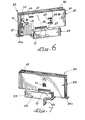
- - Figs. 6 and 7 give a perspective view, on both sides, of a shunting device in a second embodiment of the invention;
- - Fig. 8 is a schematic longitudinal section of the shunting device mentioned under Figs. 6 and 7;
- - Fig. 9 is a perspective view of the shunting device mentioned under Figs. 6 to 8, partially cutaway;
- - Figs. 10 and 11 give a perspective view, on both sides, of a shunting device in a third embodiment of the invention;
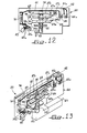
- - Fig. 12 is a schematic longitudinal section of the shunting device mentioned under Figs. 10
end 11; - - Fig. 13 is a perspective view of the shunting device mentioned under Figs. 10 to 12, partially cutaway.
- Fig. 1's cross-section shows a six-pole electric line of the armor-plated type, which is supported by a channel-shaped anodized allumi-
nium section 10. Said section exhibits in the centre someexternal protrusions 11 for its fixing, e.g. to the ceiling, in the rooms where it is employed, and some internal seats, relative to the lateral sections, for restrained fixing of strip-shaped components 12 made of dielectric material, for instance polyvinyl chloride, which in turn are equipped with housing seats for longitudinal electric wires. More precisely, provision is made for a set of threeelectric wires dielectric components 12, and for another set of three wires 13a, 14a, 15a, fitted into the otherdielectric component 12, said sets being mutually opposed in such a way that the longitudinal wires are aligned in pairs. The above wires are made of circular section copper and are fixed incomponent 12 so as to be accessable only by way of slots positioned inwardly and exhibited by theaforementioned component 12. Aground wire 16, made of circular section tinned copper as well, is then fixed in a respective median seat, produced, inwardly, in the central section ofstructural shape 10. - In the open part,
section 10 exhibits also two opposed edges._17 which limit two opposed internallongitudinal grooves 18, in which aclamping component 19 is fitted, the latter being built onto the shunting device, marked in its entirety by 20. - Figs. 2 to 5 show a first embodiment of the shunting device. With reference to the latter figures, the shunting device comprises an envelope made of electrically insulating plastic material, preferably of the type known by the trade-mark "NORYL", made up of a number of units which may be secured to each other by means of
screws 21. After the assembly, the shunting device appears to be made up of a box-type can tactunit 22 having the shape of an oblate parallelepipedon, which may be made to slide withinsection 10, betweeninsulating components 12, and of a box-type connection unit 23, which is parallelepipedon shaped too, arranged at right angles in respect of theabove unit 22 and designed to remain on the outside ofsection 10, as pointed out by the dots in Fig. 1. - On one side of the box-type contact unit 22 (Fig. 2) provision is made for three
little windows longitudinal wires inspection window 30 offuse 31, while on both sides a slot is produced for the output of the ends of theclamping component 19. The latter is butterfly shaped and is integral with coupling 19a (Fig. 4) which, in turn, is integral with operating lever 19b placed at the level of box-type unit 23 and accessable from the outside. - Coupling 19a rotates around a vertical access 32 (Fig. 4), while lever 19b is set horizontally. When
device 20 is extracted from the six-pole line 10, however, the motion ofclamping component 19 is locked by a safety stake 33 (Fig. 3) which is pushed up by a respective fly spring (not visible in the drawing), said stake being placed inunit 23 in the proximity ofcomponent 19; when the device is connected toline 10, on the other hand, saidstake 33 is pushed down by thelower edges 17 .of the section, therefore, operating lever 19b, is possible to rotatecomponent 19 by 90° in order to fit its ends intogrooves 18, in the locked position (Fig. 1), thus determining the locking of the device to the electric line. Said rotation occurs from left to right with reference to Fig. 3, starting from the unlocking position shown in the above figure. - As pointed out clearly in Figs. 4 and 5,
contact 27 is made up of a terminal fold of anelastic metal foil 27a, fastened to the envelope, at the opposite end, by means of ascrew 27b and integral with a clamp 27c. Saidfoil 27a is constantly connected to arespective cam 34 made of insulating material and integral with the top end of avertical shaft 35 which passes, with a rotational motion, through coupling 19a and integral, at the bottom, with anoperating lever 35a arranged ho- r iz.ontally next to lever 19b. By operatinglever 35a it is possible to shiftfoil 27a transversally (by means of cam 34) so as to forcecontact 27 to protrude from therespective window 24, in the phase of electric connection, as will be pointed out more clearly in the following description. - Similarly,
contacts branches elastic metal foil 36, which is U-shaped and secured to the envelope by means ofscrews 36a. The twobranches - The above selecting unit comprises a
double cam 37 made of insulating material, produced in an axially to and fro sliding coupling on a prismatic section ofvertical shaft 35, so that it can be released upward, to a first position, to connect itself tobranch 28a, or downward, to a second position, to connect itself tobranch 29a. The axial shifting of thedouble cam 37 is possible by means of a tool or simply with a finger nail, through a little window 37a (Fig. 3) placed on one side of the envelope. The rotation of thedouble cam 37 aroundaxis 32 takes place by operatinglever 35a integral withshaft 35 thedouble cam 37 being connected to the shaft itself in the direction of rotation; hence, by rotatingshaft 35 one produces the transversal shifting of eitherbranch 28a orbranch 29a (according to the position of the double cam 37) and, simultaneously that offoil 27a, by means ofcam 34. - The shifting of
lever 35a is, however, possible only after having moved lever 19b to its locking position. In view of the foregoing,lever 35a is integral with acam 35b (Fig. 5) endowed with a notch into which, when the circuit is open, ablock 38 is fitted which is capable of moving radially and is pushed toward the above cam by a respective fly spring 38a; saidblock 38 is connected to anothercam 19c as well, which is integral with lever 19b: when the latter is shifted to the locking position,cam 19c shifts block 38 outwards thus releasingcam 35b and allowing the subsequent shifting oflever 35a. It is thus possible to ensure that the electric contact occurs after the mechanical locking of the device in respect of the line. - Another block (which is not visible in the figures), placed symmetrically in respect of
block 38, has then the task of locking lever 19b whenlever 35a has reached the electric contact position, so that the mechanical unlocking cannot occur before the reversal oflever 35a to the initial position of electric disconnection. - Moreover, on that portion of
foil 36 from which the twobranches fold 36b next to which one finds an end of anelastic metal blade 39 the other end of which, it being fixed to the envelope, is connected tofuse 31. It is to be noted that saidblade 39 is elastically in constant contact with theaforementioned fold 36b. Appropriate markings may be affixed onto the envelope, e.g. 0 and F, respectively in order to indicate the disconnected and connected positions oflever 40. - The position of
lever 40 is such as to prevent the shifting oflevers 19b, 35a, when saidlever 40 is in the electric connection position, so as to determine further safety in the maneuvres. - Besides with
blade 39,fuse 31 is in contact with the end of ametal foil 41 as well, the other end of which is integral with arespective clamp 41 a. - Furthermore, 42 has been adopted to mark a sprung ground contact bound to be in constant contact with
ground wire 16, whendevice 20 is connected to the electric line; saidcontact 42 is integral with arespective clamp 42a. - From the foregoing, the functioning of the abovementioned device appears to be obvious.
- The connection of
device 20 toline 10 may take place in two positions, at a 180° rotation in respect of one another. In a first position it is possible to connectcontacts longitudinal wires longitudinal wires 13, 13a (constituting the neutral wire of the system) and toground wire 16 being unchangeable, it is possible to choose between connection towires 14 and 14a and connection towires 15 and 15a, so as to achieve a total of four contact combinations. - The choice between
wires 14 and 14a or betweenwires 15 and 15a is carried out by means of the selecting unit, namely by shifting the aforementioneddouble cam 37 upwards or downwards, before the connection ofdevice 20 toline 10. - The electric connections to the utilizing equipment are realized by passing the electric cables (not shown) through connection unit 23 (endowed on its bottom with a hole for the passage of said cables) and connecting their ends to
clamps - Let us assume we want to employ longitudinal wires 13a, 14a, 15a:
device 20 is to be fitted into the line withwires levers 19b and 35a are in their resting position shown in Fig. 3. In such phase,contacts little windows component 19 is recessed incontact unit 22, hencecontact unit 22 itself may be easily fitted betweeninsulating components 12 supporting the longitudinal wires. The fixing of the device in the desired point of the line is obtained by rotating lever 19b by 90°, from left to right with reference to Fig. 3, said rotation being possible sincestake 33 remains recessed withinunit 23 thanks to the jutting point with one of theedges 17 ofsection 10. One thus ob - tains the fitting of the ends ofcomponent 19 into the inside grooves (Fig. 1) with the consequent locking ofdevice 20 in respect of the electric line. - The rotation of lever 19b, furthermore, determines the unlocking of
lever 35a which, in its previous condition, was locked byblock 38 controlled bycam 19c. It is then possible to shift by 900lever 35a too, in the same direction as lever 19b, in order to determine the electric connection to the longitudinal wires. In fact, by shiftinglever 35a from left to right, starting from the position shown in Fig. 3, one produces an analogous motion ofcam 34 secured to the top ofshaft 35 with the subsequent transversal shifting offoil 27a so as to makecontact 27 protrude fromslot 24, until said contact, passing through the respective slot present in theadjacent insulating component 12, reaches wire 13a, as shown in Fig. 1. Thus, electric connection betweenclamp 27c and neutral wire 13a is established. - With
shaft 35 alsodouble cam 37 rotates (it being assembled on said shaft with the possibility of sliding axially, but connected to the shaft in the same rotational direction), which hence produces a transversal shifting of one of the twofoils foil 29a will be shifted and thereforecontact 29 will be made to protrude throughwindow 26 up to the point of connection to wire 15a, as shown in Fig. 1. Vice-versa, ifdouble cam 37 ha been pre-set in the top position,foil 28a will be shifted end consequently contact 28 will protrude through therespective window 25 until it reaches connection to wire 14a. Therefore, the alternative solution will be the electric connection betweenclamp 41a and wire 15a or between the above clamp and wire 14a, providedlever 40 has been brought to its closing position. In anycase clamp 42a is electrically connected toground wire 16. - In order to vary the contact combination, one
first returns lever 35a back to the starting position, after which one can rotate lever 19b (now unlocked) back to the initial position as well (Fig. 3). At thispoint device 20 may be extracted from the line in order to obtain a different selection, e.g. shiftingdouble cam 37 upward, if the latter had previously been shifted downward. Once this has been donedevice 20 is connected again, with the same orientation, to the line, hence one rotateslevers 19b and 35a, in that order, once again from left to right as described above. - If on the other hand one wants to employ
wires device 20 is connected to the line with a rotation of 1800 in respect of the previous position, so thatcontacts - Thus, without altering the connection of the cables to
clamps - As pointed out, the motion of
levers 19b, 35a may take place only if one follows a certain sequence. More precisely, in the connection maneuvre, one must first carry out the mechanical locking operation (lever 19b) and then the electric contact (lever 35a), while in the disconnection maneuvre, one must first carry out the electric disconnection (lever 35a) and then the mechanical unlocking (lever 19b). Furthermore, the special position oflever 40 allows the execution of the connection and extraction operations only when thelever 40 is in the open position. - The device according to the invention is therefore in full compliance with the most rigorous rules and regulations governing safety and the prevention of accidents at work which are presently in force.
- Figures 6 to 9 illustrate a second embodiment of the device according to the invention, in which many of the components are like those pertaining to the first embodiment described above, hence the same numerical references used above will be adopted for the unchanged components.
- Instead of the aforementioned two operating
levers 19b and 35a, relative to the first embodiment, this second embodiment exhibits asingle operating lever 43 which is made integral with both coupling 19a, bearing locking component 19, andshaft 35 bearingupper cam 34 anddouble cam 37. Just like in the previous case,cam 34 is integral withshaft 35, whiledouble cam 37 may be shifted axially along said shaft but is connected to same in the direction of rotation. - Hence, with the shifting of the
single operating lever 43 one obtains, in one direction, the mechanical locking and the electric contact, and in the other direction, the mechanical unlocking and the electric disconnection. - The electric contacts remain unchanged in respect of the ones described above, while provision is made for a switch. The latter comprises a
cylindrical block 44, made of electrically insulating material, rotating within a respective housing seat which the envelope presents internally; said block is integral with an operating lever 44a which, when at rest, is in contact withunit 22 of the device, while a little metal ball 44b is partially inserted into the above block, and is push ed towards the outside by a respective fly spring (Fig. 8). When lever 44a is rotated downward by 90° in respect of the position shown in Fig. 8, the aforementioned little ball 44b closes thecircuit connecting bend 36b offoil 36 to stiff blade 39a in contact with fuse 31 (said blade substituteselastic blade 39 relating to the first embodiment described above). When the switch is in the making position, namely when lever 44a is pushed down, the lever itself prevents the rotation oflever 43 which, in such conditions, cannot be shifted from its position at rest (Fig. 7) to the operating position, characterized by a 900 rotation. Therefore, such a shift may take place only when lever 44a is in its opening position, namely in contact with the bottom side ofunit 22, as indicated in Figs. 6 to 9, a feature which prevents the occurrence of false moves when wires are live. - As far as all other features are concerned, the device illustrated in these last Figures is identical to that of the first embodiment describ ed previously and the functioning is analogous too. Shifting
double cam 37 axially and rotating the device by 1800, four different contact combinations are again possible. - The third embodiment, illustrated in figures 10 to 13, is similar to the one illustrated with reference to Figs. 6 to 9, with the only exception relating to the different structuration of the switch. While the same numerical references have been maintained for the structural components which have not been changed, the switch suited to fit the third embodiment comprises an
equalizer 45 made of electrically insulating material, on which an elastic metal foil 45a is assembled,which is pushed up by alitte piston 45b (Fig. 12) connected to a fly spring. - In the open condition (Fig. 12), the rounded top end of foil 45a is in contact with stiff lamina 39a ( in contact with fuse 31) but remains at a distance from
flap 36b oflamina 36, thus disconnecting the circuit. In this condition, the slant ofequalizer 45 allows the shifting of operatinglever 43. - If
equalizer 45 is shifted over to the other position, lamina 45a establishes the contact between lamina 39a andflap 36b oflamina 36, thus making the circuit. In the latter position, theequalizer 45 pro trudes downwards nearlever 43 stopping its free rotation. - As far as the functioning is concerned there are no changes in respect of the device described with reference to Figs. 6 to 9.
- As may be noted, the device according to the invention, in any of the embodiments described above, allows easy selection of the contact combinations, such object requiring only the 180" rotation of the device itself when it is connected to the line and/or the previous shifting of the selecting unit (component 37). A further advantage is supplied by the possibility of inspecting
fuse 31 directly as well as the possibility to change same, throughslot 30, without having to open up. - Naturally, the invention is not limited just to the described embodiments, but several alterations and variations belonging to the field of the inventive idea are possible.
Claims (11)
Applications Claiming Priority (6)
| Application Number | Priority Date | Filing Date | Title |
|---|---|---|---|
| IT525878 | 1978-10-13 | ||
| IT708578U | 1978-10-13 | ||
| IT708678U IT7807086V0 (en) | 1978-10-13 | 1978-10-13 | SAFETY BIPOLAR ADAPTER WITH POLARITY SELECTION SWITCH ON AN ARMORED TYPE EXAPOLAR ELECTRIC LINE. |
| IT708578U IT7807085V0 (en) | 1978-10-13 | 1978-10-13 | SAFETY BIPOLAR ADAPTER WITH POLARITY SELECTION SWITCH FOR ARMORED 6-POLE ELECTRIC LINE. |
| IT708678U | 1978-10-13 | ||
| IT525878A IT1174717B (en) | 1978-10-13 | 1978-10-13 | Multipole electrical connector for E.G. electric lighting track - has movable contacts operated by lever to ensure mechanical locking before electrical connection |
Publications (2)
| Publication Number | Publication Date |
|---|---|
| EP0015356A1 true EP0015356A1 (en) | 1980-09-17 |
| EP0015356B1 EP0015356B1 (en) | 1983-08-03 |
Family
ID=27272641
Family Applications (1)
| Application Number | Title | Priority Date | Filing Date |
|---|---|---|---|
| EP79830033A Expired EP0015356B1 (en) | 1978-10-13 | 1979-09-25 | Bipolar shunting device for multipolar electric lines of the armor-plated type |
Country Status (3)
| Country | Link |
|---|---|
| US (1) | US4279456A (en) |
| EP (1) | EP0015356B1 (en) |
| DE (1) | DE2966028D1 (en) |
Cited By (11)
| Publication number | Priority date | Publication date | Assignee | Title |
|---|---|---|---|---|
| DE3214911A1 (en) * | 1982-04-22 | 1983-10-27 | Elektra GmbH & Co KG, 4904 Enger | Adaptor for busbars |
| US5422820A (en) * | 1990-04-27 | 1995-06-06 | Fanuc Ltd. | Method of drawing figures representing the machining of a polyhedral workpiece based on numerical control data |
| EP0952627A1 (en) * | 1998-04-23 | 1999-10-27 | Sicame Electrical Developments Ltd | Electrical connector |
| EP1947745A1 (en) * | 2007-01-19 | 2008-07-23 | BTICINO S.p.A. | Leaktight electrical plug for electrical ducting |
| EP2086065A1 (en) | 2008-01-31 | 2009-08-05 | BTICINO S.p.A. | Clasping device for the engagement with a suspended electrical duct |
| EP2088368A1 (en) | 2008-02-11 | 2009-08-12 | BTICINO S.p.A. | Lighting apparatus for installation on a suspended electrical duct |
| EP2113716A1 (en) | 2008-04-29 | 2009-11-04 | BTICINO S.p.A. | A light fitting to be recessed into a suspended power distribution track |
| EP2113971A1 (en) | 2008-04-29 | 2009-11-04 | BTICINO S.p.A. | A connector for a suspended power distribution track |
| EP2650981A1 (en) * | 2012-04-11 | 2013-10-16 | Hoffmeister Leuchten GmbH | Current bar |
| WO2016150741A1 (en) * | 2015-03-26 | 2016-09-29 | Philips Lighting Holding B.V. | Track based lighting and installation method |
| EP3544127A1 (en) * | 2018-03-21 | 2019-09-25 | Selux Aktiengesellschaft | Busbar adapter, arrangement comprising a conductor rail and method for connecting a conductor rail adapter in a conductor rail |
Families Citing this family (10)
| Publication number | Priority date | Publication date | Assignee | Title |
|---|---|---|---|---|
| IT8321669V0 (en) * | 1983-04-28 | 1983-04-28 | Profilux Srl | STRUCTURE OF BIPOLAR ADAPTER FOR MULTIPOLAR ELECTRIC LINES OF THE ARMORED TYPE, PART OF INSTALLATIONS FOR INTERIOR LIGHTING. |
| US4688154A (en) * | 1983-10-19 | 1987-08-18 | Nilssen Ole K | Track lighting system with plug-in adapters |
| IT8620584V0 (en) * | 1986-01-23 | 1986-01-23 | Teknolit Srl | DEVICE FOR THE ELECTRICAL SUPPLY OF LOW SAFETY OPERATING EQUIPMENT USERS. |
| GB2216343A (en) * | 1988-03-29 | 1989-10-04 | Courtney Pope Lighting Limited | Connector for an electrical supply track |
| DE10025648B4 (en) * | 2000-05-24 | 2010-04-08 | Zumtobel Lighting Gmbh | Busbar system |
| GB2414869A (en) * | 2003-08-18 | 2005-12-07 | John Ashton Sinclair | Electrical plug and busbar system |
| US6948962B1 (en) * | 2004-05-18 | 2005-09-27 | Innotec | Flexible jumper receptacle |
| DE102007026907A1 (en) * | 2007-06-11 | 2008-12-18 | Wampfler Aktiengesellschaft | Multipole conductor rail |
| DE102007026906A1 (en) * | 2007-06-11 | 2008-12-24 | Wampfler Aktiengesellschaft | Insulating profile for a multi-pole conductor line |
| DE102019126955A1 (en) * | 2019-10-08 | 2021-04-08 | Zumtobel Lighting Gmbh | Support rail for lights or electrical units |
Citations (8)
| Publication number | Priority date | Publication date | Assignee | Title |
|---|---|---|---|---|
| AU463554A (en) * | 1954-11-15 | 1955-05-19 | National Lead Company | Storage battery active material |
| US3757273A (en) * | 1970-06-30 | 1973-09-04 | K Hesse | Like adaptor for current collectors for lights electric appliances or the |
| DE2210516A1 (en) * | 1972-03-04 | 1973-09-13 | Staff & Schwarz Gmbh | ADAPTER FOR TRACKS |
| US3760133A (en) * | 1971-03-29 | 1973-09-18 | Rotaflex Ltd | Electrical lighting installations |
| DE2250738A1 (en) * | 1972-10-17 | 1974-04-18 | Hoffmeister Leuchten Kg | DETACHABLE CURRENT COLLECTOR DEVICE FOR A TRACK HAVING AN ESSENTIAL U-SHAPED CROSS-SECTION |
| US3848715A (en) * | 1972-04-01 | 1974-11-19 | K Hesse | Adaptor for an electrical power distributor track |
| DE2411976A1 (en) * | 1974-03-13 | 1976-02-05 | Erco Leuchten | Adaptor for current supply lines - has T-shaped body engaging in U-shaped rail and contact and retention flaps |
| US3993385A (en) * | 1974-01-31 | 1976-11-23 | A. Ahlstrom Osakeyhtio | Current collector, provided with a selector, for a conductor rail |
Family Cites Families (1)
| Publication number | Priority date | Publication date | Assignee | Title |
|---|---|---|---|---|
| DE2104274A1 (en) * | 1970-02-03 | 1971-08-12 | Nokia Oy Ab | Connector |
-
1979
- 1979-09-25 EP EP79830033A patent/EP0015356B1/en not_active Expired
- 1979-09-25 DE DE7979830033T patent/DE2966028D1/en not_active Expired
- 1979-09-28 US US06/080,117 patent/US4279456A/en not_active Expired - Lifetime
Patent Citations (8)
| Publication number | Priority date | Publication date | Assignee | Title |
|---|---|---|---|---|
| AU463554A (en) * | 1954-11-15 | 1955-05-19 | National Lead Company | Storage battery active material |
| US3757273A (en) * | 1970-06-30 | 1973-09-04 | K Hesse | Like adaptor for current collectors for lights electric appliances or the |
| US3760133A (en) * | 1971-03-29 | 1973-09-18 | Rotaflex Ltd | Electrical lighting installations |
| DE2210516A1 (en) * | 1972-03-04 | 1973-09-13 | Staff & Schwarz Gmbh | ADAPTER FOR TRACKS |
| US3848715A (en) * | 1972-04-01 | 1974-11-19 | K Hesse | Adaptor for an electrical power distributor track |
| DE2250738A1 (en) * | 1972-10-17 | 1974-04-18 | Hoffmeister Leuchten Kg | DETACHABLE CURRENT COLLECTOR DEVICE FOR A TRACK HAVING AN ESSENTIAL U-SHAPED CROSS-SECTION |
| US3993385A (en) * | 1974-01-31 | 1976-11-23 | A. Ahlstrom Osakeyhtio | Current collector, provided with a selector, for a conductor rail |
| DE2411976A1 (en) * | 1974-03-13 | 1976-02-05 | Erco Leuchten | Adaptor for current supply lines - has T-shaped body engaging in U-shaped rail and contact and retention flaps |
Cited By (16)
| Publication number | Priority date | Publication date | Assignee | Title |
|---|---|---|---|---|
| DE3214911A1 (en) * | 1982-04-22 | 1983-10-27 | Elektra GmbH & Co KG, 4904 Enger | Adaptor for busbars |
| US5422820A (en) * | 1990-04-27 | 1995-06-06 | Fanuc Ltd. | Method of drawing figures representing the machining of a polyhedral workpiece based on numerical control data |
| EP0952627A1 (en) * | 1998-04-23 | 1999-10-27 | Sicame Electrical Developments Ltd | Electrical connector |
| EP1947745A1 (en) * | 2007-01-19 | 2008-07-23 | BTICINO S.p.A. | Leaktight electrical plug for electrical ducting |
| EP2086065A1 (en) | 2008-01-31 | 2009-08-05 | BTICINO S.p.A. | Clasping device for the engagement with a suspended electrical duct |
| EP2088368A1 (en) | 2008-02-11 | 2009-08-12 | BTICINO S.p.A. | Lighting apparatus for installation on a suspended electrical duct |
| EP2113716A1 (en) | 2008-04-29 | 2009-11-04 | BTICINO S.p.A. | A light fitting to be recessed into a suspended power distribution track |
| EP2113971A1 (en) | 2008-04-29 | 2009-11-04 | BTICINO S.p.A. | A connector for a suspended power distribution track |
| EP2650981A1 (en) * | 2012-04-11 | 2013-10-16 | Hoffmeister Leuchten GmbH | Current bar |
| DE102012007083A1 (en) * | 2012-04-11 | 2013-10-17 | Hoffmeister Leuchten Gmbh | conductor rail |
| DE102012007083B4 (en) * | 2012-04-11 | 2013-12-12 | Hoffmeister Leuchten Gmbh | conductor rail |
| EP2650981B1 (en) | 2012-04-11 | 2016-11-09 | Hoffmeister Leuchten GmbH | Current bar |
| RU2633515C2 (en) * | 2012-04-11 | 2017-10-13 | Хоффмайстер Лойхтен Гмбх | Conductor line |
| WO2016150741A1 (en) * | 2015-03-26 | 2016-09-29 | Philips Lighting Holding B.V. | Track based lighting and installation method |
| CN107771370A (en) * | 2015-03-26 | 2018-03-06 | 飞利浦照明控股有限公司 | Illumination and installation method based on track |
| EP3544127A1 (en) * | 2018-03-21 | 2019-09-25 | Selux Aktiengesellschaft | Busbar adapter, arrangement comprising a conductor rail and method for connecting a conductor rail adapter in a conductor rail |
Also Published As
| Publication number | Publication date |
|---|---|
| EP0015356B1 (en) | 1983-08-03 |
| US4279456A (en) | 1981-07-21 |
| DE2966028D1 (en) | 1983-09-08 |
Similar Documents
| Publication | Publication Date | Title |
|---|---|---|
| EP0015356A1 (en) | Bipolar shunting device for multipolar electric lines of the armor-plated type | |
| US3485966A (en) | Slide switch | |
| EP0052768B1 (en) | Installation system made from ready-made lines with plugs and centres of connection | |
| US6105741A (en) | Electric distribution systems and electrical take-off apparatus therefor | |
| SE413572B (en) | ELECTRICAL POWER SUPPLY DEVICE FOR REMOVABLE CONNECTION OF A CONSUMER | |
| US5041704A (en) | Dual disconnect terminal assembly and switch | |
| RU2623501C2 (en) | Adapter | |
| US3991320A (en) | Electric branch-line combiner | |
| US5575679A (en) | Electrical connection terminal arrangement | |
| US3118026A (en) | Push button switch structure | |
| US6042399A (en) | Power take-off adapter for a track | |
| US4283107A (en) | Lampholder having terminals of the insulation-displaying type | |
| US4562316A (en) | High voltage linear tap changer | |
| GB2141295A (en) | Electrical assembly and drive means for a movable structure therein | |
| US3309581A (en) | Panelboard with contact members having orthogonal engageable surfaces | |
| US20030067756A1 (en) | Electrical service distribution board | |
| US4493519A (en) | Adapter plug for current supply rail systems | |
| CN110785896B (en) | Connecting device with variable electrical connection between conductor terminals | |
| US3320385A (en) | Electrical connector for tapping power from an insulation covered conductor | |
| US3188416A (en) | Circuit breaker disconnector | |
| KR910000392B1 (en) | Single phase motor | |
| US3562697A (en) | Pin contact and connector block therefor | |
| CA1065374A (en) | Connector combined with an interlocked switch | |
| KR900000830Y1 (en) | Electromagnetic contactor | |
| US1546856A (en) | Electric-switch mechanism |
Legal Events
| Date | Code | Title | Description |
|---|---|---|---|
| PUAI | Public reference made under article 153(3) epc to a published international application that has entered the european phase |
Free format text: ORIGINAL CODE: 0009012 |
|
| AK | Designated contracting states |
Designated state(s): BE CH DE FR GB NL |
|
| 17P | Request for examination filed |
Effective date: 19810227 |
|
| GRAA | (expected) grant |
Free format text: ORIGINAL CODE: 0009210 |
|
| AK | Designated contracting states |
Designated state(s): BE CH DE FR GB NL |
|
| PG25 | Lapsed in a contracting state [announced via postgrant information from national office to epo] |
Ref country code: NL Effective date: 19830803 |
|
| REF | Corresponds to: |
Ref document number: 2966028 Country of ref document: DE Date of ref document: 19830908 |
|
| ET | Fr: translation filed | ||
| NLV1 | Nl: lapsed or annulled due to failure to fulfill the requirements of art. 29p and 29m of the patents act | ||
| PLBE | No opposition filed within time limit |
Free format text: ORIGINAL CODE: 0009261 |
|
| STAA | Information on the status of an ep patent application or granted ep patent |
Free format text: STATUS: NO OPPOSITION FILED WITHIN TIME LIMIT |
|
| 26N | No opposition filed | ||
| PGFP | Annual fee paid to national office [announced via postgrant information from national office to epo] |
Ref country code: FR Payment date: 19840918 Year of fee payment: 6 |
|
| PGFP | Annual fee paid to national office [announced via postgrant information from national office to epo] |
Ref country code: DE Payment date: 19840929 Year of fee payment: 6 |
|
| PGFP | Annual fee paid to national office [announced via postgrant information from national office to epo] |
Ref country code: CH Payment date: 19841001 Year of fee payment: 6 |
|
| PGFP | Annual fee paid to national office [announced via postgrant information from national office to epo] |
Ref country code: BE Payment date: 19841231 Year of fee payment: 6 |
|
| PG25 | Lapsed in a contracting state [announced via postgrant information from national office to epo] |
Ref country code: GB Effective date: 19880925 |
|
| PG25 | Lapsed in a contracting state [announced via postgrant information from national office to epo] |
Ref country code: CH Effective date: 19880930 Ref country code: BE Effective date: 19880930 |
|
| BERE | Be: lapsed |
Owner name: F. LLI ZUCCHINI S.P.A. Effective date: 19880930 |
|
| PG25 | Lapsed in a contracting state [announced via postgrant information from national office to epo] |
Ref country code: FR Free format text: LAPSE BECAUSE OF NON-PAYMENT OF DUE FEES Effective date: 19890531 |
|
| REG | Reference to a national code |
Ref country code: CH Ref legal event code: PL |
|
| GBPC | Gb: european patent ceased through non-payment of renewal fee | ||
| PG25 | Lapsed in a contracting state [announced via postgrant information from national office to epo] |
Ref country code: DE Effective date: 19890601 |
|
| REG | Reference to a national code |
Ref country code: FR Ref legal event code: ST |