EP0016428A2 - Device for improving the legibility of passive displays - Google Patents
Device for improving the legibility of passive displays Download PDFInfo
- Publication number
- EP0016428A2 EP0016428A2 EP80101331A EP80101331A EP0016428A2 EP 0016428 A2 EP0016428 A2 EP 0016428A2 EP 80101331 A EP80101331 A EP 80101331A EP 80101331 A EP80101331 A EP 80101331A EP 0016428 A2 EP0016428 A2 EP 0016428A2
- Authority
- EP
- European Patent Office
- Prior art keywords
- display
- fluorescent body
- fluorescent
- colored
- electrochromic
- Prior art date
- Legal status (The legal status is an assumption and is not a legal conclusion. Google has not performed a legal analysis and makes no representation as to the accuracy of the status listed.)
- Withdrawn
Links
- 230000003287 optical effect Effects 0.000 claims abstract description 26
- 239000007788 liquid Substances 0.000 claims description 14
- 239000003792 electrolyte Substances 0.000 claims description 8
- 239000002245 particle Substances 0.000 claims description 8
- 239000007850 fluorescent dye Substances 0.000 claims description 6
- 239000000975 dye Substances 0.000 claims description 5
- 238000010521 absorption reaction Methods 0.000 claims description 4
- 230000008878 coupling Effects 0.000 claims description 4
- 238000010168 coupling process Methods 0.000 claims description 4
- 238000005859 coupling reaction Methods 0.000 claims description 4
- 239000000463 material Substances 0.000 claims description 4
- 239000000049 pigment Substances 0.000 claims description 4
- 230000005540 biological transmission Effects 0.000 claims description 3
- 239000000725 suspension Substances 0.000 claims description 3
- 229920000049 Carbon (fiber) Polymers 0.000 claims description 2
- 239000000853 adhesive Substances 0.000 claims description 2
- 230000001070 adhesive effect Effects 0.000 claims description 2
- 239000004917 carbon fiber Substances 0.000 claims description 2
- 238000010276 construction Methods 0.000 claims description 2
- 238000007650 screen-printing Methods 0.000 claims description 2
- 239000012780 transparent material Substances 0.000 claims description 2
- 230000000112 colonic effect Effects 0.000 claims 1
- 239000003086 colorant Substances 0.000 claims 1
- 238000006073 displacement reaction Methods 0.000 claims 1
- 239000000835 fiber Substances 0.000 claims 1
- 239000006249 magnetic particle Substances 0.000 claims 1
- 238000011161 development Methods 0.000 description 17
- 230000018109 developmental process Effects 0.000 description 17
- 230000002745 absorbent Effects 0.000 description 3
- 239000002250 absorbent Substances 0.000 description 3
- 239000004973 liquid crystal related substance Substances 0.000 description 3
- 238000000034 method Methods 0.000 description 3
- 238000004040 coloring Methods 0.000 description 2
- 230000000694 effects Effects 0.000 description 2
- 230000003321 amplification Effects 0.000 description 1
- 230000037237 body shape Effects 0.000 description 1
- 230000005611 electricity Effects 0.000 description 1
- 238000005516 engineering process Methods 0.000 description 1
- 230000002349 favourable effect Effects 0.000 description 1
- 230000012447 hatching Effects 0.000 description 1
- 238000003199 nucleic acid amplification method Methods 0.000 description 1
- 239000002244 precipitate Substances 0.000 description 1
- 230000005855 radiation Effects 0.000 description 1
- 239000000126 substance Substances 0.000 description 1
Images

Classifications
-
- G—PHYSICS
- G02—OPTICS
- G02F—OPTICAL DEVICES OR ARRANGEMENTS FOR THE CONTROL OF LIGHT BY MODIFICATION OF THE OPTICAL PROPERTIES OF THE MEDIA OF THE ELEMENTS INVOLVED THEREIN; NON-LINEAR OPTICS; FREQUENCY-CHANGING OF LIGHT; OPTICAL LOGIC ELEMENTS; OPTICAL ANALOGUE/DIGITAL CONVERTERS
- G02F1/00—Devices or arrangements for the control of the intensity, colour, phase, polarisation or direction of light arriving from an independent light source, e.g. switching, gating or modulating; Non-linear optics
- G02F1/01—Devices or arrangements for the control of the intensity, colour, phase, polarisation or direction of light arriving from an independent light source, e.g. switching, gating or modulating; Non-linear optics for the control of the intensity, phase, polarisation or colour
- G02F1/13—Devices or arrangements for the control of the intensity, colour, phase, polarisation or direction of light arriving from an independent light source, e.g. switching, gating or modulating; Non-linear optics for the control of the intensity, phase, polarisation or colour based on liquid crystals, e.g. single liquid crystal display cells
- G02F1/133—Constructional arrangements; Operation of liquid crystal cells; Circuit arrangements
- G02F1/1333—Constructional arrangements; Manufacturing methods
- G02F1/1335—Structural association of cells with optical devices, e.g. polarisers or reflectors
- G02F1/1336—Illuminating devices
- G02F1/133617—Illumination with ultraviolet light; Luminescent elements or materials associated to the cell
-
- G—PHYSICS
- G02—OPTICS
- G02F—OPTICAL DEVICES OR ARRANGEMENTS FOR THE CONTROL OF LIGHT BY MODIFICATION OF THE OPTICAL PROPERTIES OF THE MEDIA OF THE ELEMENTS INVOLVED THEREIN; NON-LINEAR OPTICS; FREQUENCY-CHANGING OF LIGHT; OPTICAL LOGIC ELEMENTS; OPTICAL ANALOGUE/DIGITAL CONVERTERS
- G02F1/00—Devices or arrangements for the control of the intensity, colour, phase, polarisation or direction of light arriving from an independent light source, e.g. switching, gating or modulating; Non-linear optics
- G02F1/01—Devices or arrangements for the control of the intensity, colour, phase, polarisation or direction of light arriving from an independent light source, e.g. switching, gating or modulating; Non-linear optics for the control of the intensity, phase, polarisation or colour
- G02F1/0102—Constructional details, not otherwise provided for in this subclass
- G02F1/0105—Illuminating devices
Definitions
- the invention relates to a display technique according to the preamble of claim 1.
- FLAD fluorescence-activated display
- a FLAD a "fluorescence plate” is located behind a light valve, which can be switched in some areas between a translucent and a light-blocking state.
- This plate contains a fluorescent substance, is mirrored on its four narrow sides and has notches on the back, each aligned with one of the switchable valve areas.
- the fluorescent plate collects a large part of the ambient light that hits it through fluorescence scattering and subsequent (total) reflections at its interfaces, transmits this radiation inside and couples it out with increased intensity at the notches.
- the brightness amplification factor of the fluorescent plate is given in a first approximation by the ratio of the light-collecting to the light-emitting plate surface. More details on the structure and mode of operation of a FLAD can be found in DE-OS 25 54 226.
- the FLAD version described undoubtedly has good optical qualities, but has not yet a particularly high level of efficiency: the fluorescent plate is partly covered by the light valve and therefore has only a relatively small collector area; the valves previously used work with polarizers, which significantly weaken the light passing through. These losses result in a moderate luminous efficiency of around 30%.
- the main advantage of the invention lies in the fact that the visibility of passive displays is increased considerably with a device according to the invention.
- the display of Figure 1 contains in particular a fluorescent plate 1, which is compared to e.g. an electrochromic display, consisting of a transparent support 3 and an electrochromic layer 4, is.
- Plate-shaped elevations 5 are attached to the transparent carrier 3 and are adapted to the switchable zones 6 in the electrochromic layer 4.
- the electrochromic layer 4 is followed by the electrolyte in which a diffuse scatterer is embedded.
- the arrangement is completed by a back electrode, not shown.
- Mirroring 7 is provided on the narrow sides of the fluorescent plate 1.
- the fluorescence plate 1 is integrated in an electrochromic display.
- a diffuse spreader for example a felt, is designated and at 9 the electrolyte.
- the thicknesses of fluorescent plate 1 and transparent support 3 are different. In order to obtain a preferred outward coupling, the fluorescent plate 1 must be significantly thicker than the transparent carrier layer 3.
- FIG. 3 shows a partial section of an electrochromic display in which two light beams 10 are drawn in with dashed lines to illustrate parallax effects. This figure is intended to illustrate that the switchable area 6 must be larger than the plate-shaped optical contact 5 for parallax compensation.
- FIG. 4 shows a variant of the electrochromic display, in which each display element consists of an electrochromic display, the front first electrode 6 being applied directly to the fluorescent body 1.
- the electrolyte 9 is dotted in this figure and the felt 8 is shown with double hatching.
- the contact surfaces 12 between the fluorescent body 1 and the housing 11 are mirrored.
- FIG. 5 shows a display in which the electrical or magnetic dipoles are shown in two different switching states 13, 14. 13 shows the transparent state and 14 the reflected state.
- Figure 6 shows a device using an electrophoretic display.
- 15 denotes a carrier liquid in which electrostatically charged particles 16 are permanently suspended.
- the suspending liquid must be absorbent and the particles reflective.
- a liquid-crystalline display is shown in FIG.
- the liquid crystals are identified by 17 and the pleochroic dyes by 18.
- the two different switching states are shown in the display.
- the main advantage of the invention lies in the fact that in a device of a FK and a passivated - are combined ver display miteinerander that even such displays, which will work with unpolarized light brightened by fluorescent body from the environment.
- the proposed arrangement leads to a considerable increase in the visibility of the passive displays used.
- the invention had the object of the recognizability of passive displays by the best possible use of Verstärkun g fluorescence plate seigenschaften while largely using known display technologies improve.
- the light collected by the fluorescent body illuminates the display area of the display and electronically switches the display between a state that largely absorbs this light and a state that this light reflected, scattered or re-emitted through the FK to the observer.
- the proposed method works without special mechanically moving parts and without polarizers.
- the light collecting surface is equal to the surface of the fluorescent body, since the control of the light decoupling via absorption and reflection does not switch off the display elements as with the conventional FLAD (fluorescence-activated display, liquid crystal display between LC and observer).
- the display displays can be illuminated in two ways, firstly by direct optical contact between the display and the LC, and secondly by coupling the fluorescent light from the LC to the display.
- direct optical contact the display image is determined by the form of the contact.
- the contact has the shape of the display segments.
- the LC must be provided with light exit windows, preferably plate-shaped elevations, in the area of the display segments.
- the plate-shaped elevations are advantageously laterally leveled.
- Such displays in which the switchable layer does not have to be applied to a transparent support, but the associated front electrode forms the surface of the display area (for example an electrochromic solid-state display), can be dispensed with the aforementioned optical contact.
- the contacting areas are elevations on the FK in direct optical contact.
- the contacts can also be surveys on the display.
- the contacts can consist of a transparent material and on the surface of the display or that of the FK, e.g. be applied by screen printing.
- the contacting is an adhesive at the same time. It is also advantageous if the absorption of the absorbing switching state of the passive display and the emission of the fluorescent body are matched to one another.
- the optically non-contacting areas for increasing the contrast are covered with a contrast film.
- the optically non-contacting areas of the display are colored.
- the color of the film or the coloring is preferably in accordance with the absorbent state of the display.
- the non-switchable areas of the optical contact are mirrored on the LC surface (12 in FIG. 4).
- the non-switchable areas of the optical contact at the interfaces to the LC are colored in the color of the absorbing display state (cf. FIG. 12 in FIG. 4).
- the display is a solid-electrochromic display or a liquid electrochromic display according to the basic D a R position is in Fig. 1 .. Preferred electrochromic materials and layers of W0 3 or M o 0 3. In the case of a fixed electrochromic display, the display segments can be applied directly to the LC.
- the switchable area of the ECD is selected to be larger or at least as large as the optical contact. According to FIG. 3, parallax compensation results from a smaller optical contact than the area of the switchable area. Thin contacting layers are also advantageous for increasing the observation angle.
- Areas of the internal diffuse spreader 8 in FIG. 2 b or FIG. 3 in the liquid electrochromic display which do not contribute to the display are advantageously colored in the color of the absorbing state of the electrochromic layer. This becomes important when the switchable area has to be selected very small for very small displays.
- areas of the internal diffuse spreader in the liquid-electrochromic display that contribute to the display are colored fluorescent. In this way, multicolored displays can be generated.
- one of the transparent supports (from FIG. 1) of ECD electrodes and electrochromic layer is identical to the LC.
- the carrier of the rear electrodes must also be transparent or an LC.
- the refractive index of the electrolyte roughly matches that of the LC.
- the electrochromic layer as well as the diffuse spreaders only exist in the display area and the whole system is mirrored like a FK.
- the thickness of the LC (1) is chosen to be substantially greater than that of the rear layer (3).
- the light is preferably coupled out in the direction of the observer.
- the diffuse scatterer (8 in FIG. 2) is colored with a different fluorescent dye than is present in the LC.
- This second fluorescent dye absorbs light from the LC and emits at a longer wavelength.
- an ECD structure is brought to the LC for each independent switching element (display segment), as outlined in FIG. 4.
- the LC replaces the transparent support (3 in Figure 1) of the front electrode.
- the contact points can be mirrored (12) or colored in the color of the absorbing display state.
- an electrophoretic display (see FIG. 6) is used as the passive display. In one switching state, electrically charged particles are moved to the front (lower switching state in FIG. 6) and in the other switching state to the rear (upper switching state).
- the liquid is colored to absorb the fluorescent light, in particular black.
- the electrically charged pigments (16) should be colored, preferably white.
- a passive display in which the absorbing and reflecting state is generated by orienting magnetic dipoles in a liquid.
- the transparent (13) and below (14) the opaque state is shown.
- state 13 display transparent, a reflector film must be attached to the back.
- the magnetically orientable particles are colored.
- a passive display in which electrical dipoles can be oriented in a suspension.
- the two switching states correspond to those in FIG. 5.
- coloring is an advantage with the electrical e.
- a passive display in which carbon fibers or other rod-shaped particles (e.g. herapatite) are suspended in other liquids. You can switch between a transparent state (13 in Figure 5 above) and an opaque (black) disordered or ordered (14 in Figure 5 below).
- rod-shaped particles e.g. herapatite
- a passive display in which pleochroic dyes are embedded between liquid crystals. Ent According to the illustration in FIG. 7, a switch is made between a non-absorbing state (FIG. 7 above) and an absorbing state (FIG. 7 below).
- the pleochroic dyes are chosen to be fluorescent.
- the fluorescent body will predominantly be a plate with mirrored side surfaces and be contacted with the precipitate on its rear side;
- Other body shapes are also conceivable (DE-OS 27 24 748) and / or light exit windows on the front of the body (DE-OS 25 54 226).
Abstract
Zur Steigerung der Erkennbarkeit bei passiven Displays wird über Auskoppelstellen des Fluoreszenzkörpers oder durch direkte optische Kontaktierung mit dem Fluoreszenzkörper eine Beleuchtung der Anzeigeelemente erreicht. Die passiven Displays können zwischen zwei optischen Zuständen geschaltet werden. In einem Schaltzustand des passiven Displays wird das Fluoreszenzlicht absorbiert und im anderen Schaltzustand diffus reflektiert und damit ausgekoppelt.To increase the visibility of passive displays, the display elements are illuminated by decoupling the fluorescent body or by direct optical contacting with the fluorescent body. The passive displays can be switched between two optical states. The fluorescent light is absorbed in one switching state of the passive display and diffusely reflected in the other switching state and thus coupled out.
Description
Die Erfindung betrifft eine Darstellungstechnik gemäß dem Oberbegriff des Anspruchs 1.The invention relates to a display technique according to the preamble of claim 1.
Displays, die kein eigenes Licht erzeugen, sondern nur das Licht der Umgebung modulieren, müssendann, wenn sie auch unter ungünstigen Eelligkeitsverhältnissen anzeigen sollen, mit einer Zusatzbeleuchtung ausgerüstet werden. Diese Lichtquelle verbraucht in aller Regel Strom und stellt daher einen der wesentlichen Vorzüge einer passiven Anzeigevorrichtung -den extrem geringen Leistungsbedarf- infrage. Man ist daher seit jeher um die Realsierung eines Displaytyps bemüht, der mit möglichst wenig künstlichem Licht auskommt.Displays that do not generate their own light, but only modulate the light of the surroundings, must be equipped with additional lighting if they are also to display under unfavorable brightness conditions. This light source generally consumes electricity and therefore questions one of the essential advantages of a passive display device - the extremely low power requirement. For this reason, efforts have always been made to implement a display type that uses as little artificial light as possible.
Auf diesem Weg ist man mit der Entwicklung des sog. "fluoreszenzaktivierten Displays" (FLAD) einen großen Schritt vorangekommen. Bei einem FLAD befindet sich hinter einem Lichtventil, das bereichsweise zwischen einem lichtdurchlässigen und einem lichtsperrenden Zustand geschaltet werden kann, eine "Fluoreszenzplatte". Diese Platte enthält einen Fluoreszenzstoff, ist an ihren vier Schmalseiten verspiegelt und hat auf ihrer Rückseite Kerben, die jeweils mit einem' der schaltbaren Ventilbereiche fluchten. Die Fluoreszenzplatte sammelt einen Großteil des auf sie treffenden Umgebnngslichts durch Fluoreszenzstreuung und nachfolgende (Total-) Reflexionen an ihren Grenzflächen, leitet diese Strahlung in ihrem Inneren fort und koppelt sie mit erhöhter Intensität an den Kerben nach vorn aus. Der Helligkeitsverstärkungsfaktor der Fluoreszenzplatte ist in erster Näherung gegeben durch das Verhältnis der lichtsammelnden zur lichtabgebenden Plattenfläche. Nähere Einzelheiten über den Aufbau und die Wirkungsweise eines FLAD's können der DE-OS 25 54 226 entnommen werden.In this way, the development of the so-called "fluorescence-activated display" (FLAD) is a major one Step forward. In the case of a FLAD, a "fluorescence plate" is located behind a light valve, which can be switched in some areas between a translucent and a light-blocking state. This plate contains a fluorescent substance, is mirrored on its four narrow sides and has notches on the back, each aligned with one of the switchable valve areas. The fluorescent plate collects a large part of the ambient light that hits it through fluorescence scattering and subsequent (total) reflections at its interfaces, transmits this radiation inside and couples it out with increased intensity at the notches. The brightness amplification factor of the fluorescent plate is given in a first approximation by the ratio of the light-collecting to the light-emitting plate surface. More details on the structure and mode of operation of a FLAD can be found in DE-OS 25 54 226.
Die geschilderte FLAD-Version verfügt zweifellos über gute optische Qualitäten, hat aber noch keinen besonders hohen Wirkungsgrad : Die Fluoreszenzplatte-wird zum Teil von dem Lichtventil abgedeckt und hat daher nur eine relativ kleine Kollektorfläche; die bisher verwendeten Ventile arbeiten mit Polarisatoren, die durchgehendes Licht erheblich schwächen. Diese Verluste ergeben eine nur mäßige Lichtausbeute von etwa 30%.The FLAD version described undoubtedly has good optical qualities, but has not yet a particularly high level of efficiency: the fluorescent plate is partly covered by the light valve and therefore has only a relatively small collector area; the valves previously used work with polarizers, which significantly weaken the light passing through. These losses result in a moderate luminous efficiency of around 30%.
Der Erfindung liegt die Aufgabe zugrunde, mit möglichst einfachen Mitteln die Erkennbarkeit von passiven Displays erheblich zu steigern. Dies wird nach einem Verfahren zur Verbesserung der Erkennbarkeit von Vorrichtungen zur optischen Darstellung von Informationen bestehend aus
- a) einem Körper(Fluoreszenzkörper), der aus einem Material mit einem Brechungsindex größer 1 besteht, fluoreszierende Partikel enthält und auftreffendes Licht durch Fluoreszenzstreuung und nachfolgende Reflexionen an seinen Grenzflächen sammelt,
- b) einem passiven Display, der elektronisch steuerbar zwischen einem absorbierenden 'Zustand und einem Zustand der Transmission (reflektierender Hintergrund) oder Reflexion schaltet, dadurch gelöst,daß sich der passive Display in dem Fluoreszenzkörper oder vom Beobachter gesehen hinter dem Fluoreszenzkörper befindet, daß ferner Vorkehrungen getroffen sind, die durch Anbringen von Auskoppelstellen am Fluoreszenzkörper oder durch optische Kontaktierung das vom Fluoreszenzkörper gesammelte Licht die Anzeigeelemente beleuchtet.
- a) a body (fluorescent body) which consists of a material with a refractive index greater than 1, contains fluorescent particles and collects incident light by fluorescence scattering and subsequent reflections at its interfaces,
- b) a passive display, which switches electronically controllably between an absorbing state and a state of transmission (reflecting background) or reflection, solved in that the passive display is located in the fluorescent body or behind the fluorescent body as seen by the observer, that further precautions are made, which illuminates the display elements by attaching decoupling points to the fluorescent body or by optical contacting the light collected by the fluorescent body.
Der wesentliche Vorteil der Erfindung liegt darin begründet, daß mit einer Vorrichtung nach der Erfindung die Erkennbarkeit von passiven Displays erheblich gesteigert wird.The main advantage of the invention lies in the fact that the visibility of passive displays is increased considerably with a device according to the invention.
Weitere vortelhafte Ausgestaltungen und Weiterbildungen der Erfindung sind Gegenstand besonderer Ansprüche.Further advantageous refinements and developments of the invention are the subject of special claims.
Der Lösungsvorschlag soll nun an Hand bevorzugter Ausführungsbeispiele in Verbindung mit den Figuren der Zeichnung näher erläutert werden. In den Figuren sind einander entsprechende Teile mit gleichen Bezugszeichen versehen. Es zeigen
- Figur 1 in einem Seitenschnitt ein elektrochromes Display mit einer Fluoreszenzplatte,
Figur 2 einen Seitenschnitt eines elektrochromen Displays, bei dem der Fluoreszenzkörper ein Bestandteil des Displays ist,Figur 3 die Parallaxendarstellung bei elektrochrömen Displays,- Figur 4 ein elektrochromes Display, bei dem das Display in einem Anzeigeelement untergebracht ist,
- Figur 5 einen Seitenschnitt eines Displays, bei dem die Schaltung durch Orientieren elektrischer oder magnetischer Dipole erreicht wird,
Figur 6 einen Seitenschnitt eines Displays, bei dem die Schaltung durch elektrophoretische Effekte bewirkt wird,Figur 7 einen Seitenschnitt durch ein Display, bei dem in einem flüssigkristallinem System pleo-chroitische Farbstoffe eingelagert sind.
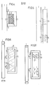
- FIG. 1 shows a side section of an electrochromic display with a fluorescent plate,
- FIG. 2 shows a side section of an electrochromic display in which the fluorescent body is a component of the display,
- FIG. 3 shows the parallax display in electrochromic displays,
- FIG. 4 shows an electrochromic display in which the display is housed in a display element,
- FIG. 5 shows a side section of a display in which the circuit is achieved by orienting electrical or magnetic dipoles,
- FIG. 6 shows a side section of a display in which the switching is effected by electrophoretic effects,
- 7 shows a side section through a display in which pleochroic dyes are embedded in a liquid-crystalline system.
In den Figuren sind für ein Verständnis der Erfindung nicht unbedingt erforderliche Einzelteile eines Displays, beispielsweise die elektrischen Zuleitungen der Übersicht halber nicht eingezeichnet.The individual parts of a display that are not absolutely necessary for an understanding of the invention, for example the electrical feed lines, are not shown in the figures for the sake of clarity.
Das Display der Figur 1 enthält im einzelnen eine Fluoreszenzplatte 1, der gegenüber z.B. ein elektrochromer Display, bestehend aus einem transparenten Träger 3 und einer elektrochromen Schicht 4, liegt,. Auf-dem transparenten Träger 3 sind plattenförmige Erhebungen 5 angebracht, die den umschaltbaren Zonen 6 in der elektrochromen Schicht 4 angepaßt sind. An die elektrochrome Schicht 4 schließt sich bei flüssigelektrochromen Displays der Elektrolyt an, in dem ein diffuser Streuer eingelagert ist. Die Anordnung wird durch eine nicht dargestellte Rückelektrode abgeschlossen. An den Schmalseiten der Fluoreszenzplatte 1 sind Verspiegelungen 7 angebracht.The display of Figure 1 contains in particular a fluorescent plate 1, which is compared to e.g. an electrochromic display, consisting of a
Nach der Darstellung in der Figur 2 ist die Fluoreszenzplatte 1 in einem elektrochromen Display integriert. Mit 8 ist ein diffuser Streuer, z.B. ein Filz, bezeichnet und mit 9 der Elektrolyt. Die Dicken von Fluoreszenzplatte 1 und transparenten Träger 3 sind unterschiedlich. Um eine bevorzugte Auskoppelung nach vorn zu erhalten, muß die Fluoreszenzplatte 1 wesentlich dicker als die transparente Trägerschicht 3 sein.According to the illustration in FIG. 2, the fluorescence plate 1 is integrated in an electrochromic display. With 8 a diffuse spreader, for example a felt, is designated and at 9 the electrolyte. The thicknesses of fluorescent plate 1 and
In der Figur 3 ist ein Teilausschnitt eines elektrochromen Displays dargestellt, in dem zur Verdeutlichung von parallaxen Effekten, zwei Lichtstrahlen 10 gestrichelt eingezeichnet sind. Mit dieser Figur soll veranschaulicht werden, daß zum Parallaxen-Ausgleich der umschaltbare Bereich 6 größer sein muß als die plattenförmige optische Kontaktierung 5.FIG. 3 shows a partial section of an electrochromic display in which two light beams 10 are drawn in with dashed lines to illustrate parallax effects. This figure is intended to illustrate that the
Figur 4 zeigt eine Variante des elektrochromen Displays, bei dem jedes Anzeigeelement aus einem elektrochromen Display besteht, wobei die vordere erste Elektrode 6 direkt auf dem Fluoreszenzkörper 1 aufgebracht ist. Der Elektrolyt 9 ist in dieser Figur punktiert und der Filz 8 doppelt schraffiert dargestellt. Dem elektrochromen Display umgibt ein Gehäuse 11 mit der nicht dargestellten Rückelektrode. Die Kontaktflächen 12 zwischen dem Fluoreszenzkörper 1 und dem Gehäuse 11 sind verspiegelt.FIG. 4 shows a variant of the electrochromic display, in which each display element consists of an electrochromic display, the front
In der Figur 5 ist ein Display dargestellt, bei dem die elektrischen oder magnetischen Dipole in zwei verschiedenen Schaltzuständen 13, 14 gezeigt sind. Mit 13 ist der transparente und mit 14 der reflektierte Zustand dargestellt.FIG. 5 shows a display in which the electrical or magnetic dipoles are shown in two
Figur 6 zeigt eine Vorrichtung unter Verwendung eines elektrophoretischen Display. Mit 15 ist eine Trägerflüssigkeit bezeichnet, in der dauernd elektrostatisch aufgeladene Partikel 16 suspendiert sind. Im oberen Teil ist der absorbierende Zustand und im unteren Teil der reflektierende Zustand dargestellt. Dabei muß die suspendierende Flüssigkeit absorbierend und die Partikel reflektierend sein.Figure 6 shows a device using an electrophoretic display. 15 denotes a carrier liquid in which electrostatically
In der Figur 7 ist ein flüssigkristallines Display dargestellt. Mit 17 sind die Flüssigkristalle und mit 18 die pleochroitischen Farbstoffe gekennzeichnet. Im Display sind die beiden verschiedenen Schaltzustände dargestellt.A liquid-crystalline display is shown in FIG. The liquid crystals are identified by 17 and the pleochroic dyes by 18. The two different switching states are shown in the display.
Der wesentliche Vorteil der Erfindung liegt darin begründet, daß bei einer Vorrichtung ein FK und ein passi- ver Display so miteinerander kombiniert werden, daß auch solche Displays, die mit unpolarisiertem Licht arbeiten vom Fluoreszenzkörper gegenüber der Umgebung aufgehellt werden. Die vorgeschlagene Anordnung führt zu einer erheblichen Steigerung der Erkennbarkeit der verwendeten passiven Displays.The main advantage of the invention lies in the fact that in a device of a FK and a passivated - are combined ver display miteinerander that even such displays, which will work with unpolarized light brightened by fluorescent body from the environment. The proposed arrangement leads to a considerable increase in the visibility of the passive displays used.
Der Erfindung lag die Aufgabe zugrunde, die Erkennbarkeit von passiven Displays durch möglichst optimale Ausnutzung der Verstärkungseigenschaften der Fluoreszenzplatte unter weitgehender Verwendung bekannter Displaytechniken zu verbessern.The invention had the object of the recognizability of passive displays by the best possible use of Verstärkun g fluorescence plate seigenschaften while largely using known display technologies improve.
Diese Aufgabe wird erfindungsgemäß durch eine Vorrich- .tung mit den Merkmalen des Patentanspruchs 1 gelöst.This object is achieved according to the invention by a device with the features of patent claim 1.
Wesentlich bei dieser Vorrichtung ist, daß das vom Fluoreszenzkörper gesammelte Licht den Anzeigebereich des Displays beleuchtet und den Display elektronisch zwischen einem Zustand schaltet, der dieses Licht weitgehend absorbiert und einem Zustand, der dieses Licht durch den FK hindurch zum Beobachter reflektiert, streut oder reemittiert.It is essential in this device that the light collected by the fluorescent body illuminates the display area of the display and electronically switches the display between a state that largely absorbs this light and a state that this light reflected, scattered or re-emitted through the FK to the observer.
Das vorgeschlagene Verfahren kommt ohne besondere mechanisch bewegliche Teile und ohne Polarisatoren aus. Die Lichtsammelfläche ist gleich der Oberfläche des Fluoreszenzkörpers, da die Steuerung der Lichtauskoppelung über Absorption und Reflexion keine Abschaltung der Anzeigeelemente wie beim herkömmlichen FLAD (Fluoreszenzaktivierter Display, Flüssigkristallanzeige zwischen FK und Beobachter) bewirkt.The proposed method works without special mechanically moving parts and without polarizers. The light collecting surface is equal to the surface of the fluorescent body, since the control of the light decoupling via absorption and reflection does not switch off the display elements as with the conventional FLAD (fluorescence-activated display, liquid crystal display between LC and observer).
Die Beleuchtung der Displayanzeigen läßt sich auf zwei Wegen erreichen und zwar, einmal durch einen direkten optischen Kontakt zwischen Display und FK, zum anderen durch Auskoppeln des Fluoreszenzlichtes aus dem FK auf den Display. Beim direkten optischen Kontakt wird das Displaybild durch die Form der Kontaktierung bestimmt. Zweckmäßigerweise hat die Konta tierung die Form der Anzeigesegmente.The display displays can be illuminated in two ways, firstly by direct optical contact between the display and the LC, and secondly by coupling the fluorescent light from the LC to the display. With direct optical contact, the display image is determined by the form of the contact. Expediently, the contact has the shape of the display segments.
Sofern die Kontaktierung sich über die gesamte Displayfläche erstreckt, muß für eine Auskoppelung ausschließlich im Bereich der Anzeigesegmente gesorgt werden. Dies erfolgt, wie in Figur 2 für elektrochrome Displays dargestellt, durch eine integrierte Anordnung von Display und FK mit den in Anspruch 25 genannten Eigenschaften.If the contact extends over the entire display area, decoupling must only be provided in the area of the display segments. This is done, as shown in FIG. 2 for electrochromic displays, by an integrated arrangement of display and LC with the properties mentioned in claim 25.
Bei Display-Konstruktionen, bei denen Flüssigkeiten Verwendung finden und der Fluoreszenzkörper Bestandteil der Gefäßwand (vgl. Figur 4) ist, müssen Vorkehrungen getroffen werden, daß durch angrenzende Wände, die Fluoreszenzlicht auskoppeln, keine unerwünschte Anzeige erzeugt wird. Dies wird, wie in Figur 4 gezeigt, entweder durch Absorption dieses Lichtes in einer Farbschicht (12) zwischen FK und Wand oder durch Verspiegelung (12) dieses Bereichs erreicht.In display constructions in which liquids are used and the fluorescent element is part of the vessel wall (cf. FIG. 4), precautions must be taken that through adjacent walls, the No undesired ad has generated F luoreszenzlicht couple out. As shown in FIG. 4, this is achieved either by absorption of this light in a color layer (12) between the LC and the wall or by mirroring (12) of this area.
Ist kein optischer Kontakt zwischen FK und Display vorhanden, so muß der FK im Bereich der Anzeigesegmente mit Lichtaustrittsfenstern, vorzugsweise plattenförmigen Erhebungen, versehen sein.If there is no optical contact between the LC and the display, the LC must be provided with light exit windows, preferably plate-shaped elevations, in the area of the display segments.
Vorteilhafterweise sind die plattenförmigen Erhebungen seitlich verspegelt. Solche Displays, bei denen die schaltbare Schicht nicht auf einem transparenten Träger aufgebracht werden muß, sondern die zugehörige vordere Elektrode die Oberfläche des Anzeigebereichs bildet, (beispielsweise ein elektrochromer Festkörperdisplay) kann auf den vorher erwähnten optischen Kontakt verzichtet werden.The plate-shaped elevations are advantageously laterally leveled. Such displays, in which the switchable layer does not have to be applied to a transparent support, but the associated front electrode forms the surface of the display area (for example an electrochromic solid-state display), can be dispensed with the aforementioned optical contact.
Zu einer Weiterbildung der Erfindung sind im direkten optischen Kontakt die Kontaktierungsflächen Erhebungen am FK. Entsprechend können die Kontaktierungen auch Erhebungen am Display sein.For a further development of the invention, the contacting areas are elevations on the FK in direct optical contact. Correspondingly, the contacts can also be surveys on the display.
Nach einer weiteren Ausbildung der Erfindung können die Kontaktierungen aus einem transparenten Material bestehen und auf die Oberfläche des Displays oder die des FK,z.B. durch Siebdruck aufgebracht sein.According to a further embodiment of the invention, the contacts can consist of a transparent material and on the surface of the display or that of the FK, e.g. be applied by screen printing.
Es ist vorteilhaft, wenn die Kontaktierung dabei gleichzeitig ein Klebstoff ist. Weiterhin ist es von Vorteil, wenn die Absorption des absorbierenden Schaltzustandes des passiven Displays und die Emission des Fluoreszenzkörpers aufeinander abgestimmt sind.It is advantageous if the contacting is an adhesive at the same time. It is also advantageous if the absorption of the absorbing switching state of the passive display and the emission of the fluorescent body are matched to one another.
In einer Weiterbildung der Erfindung werden die optisch nicht kontaktierenden Bereiche zur Kontrasterhöhung mit einer Kontrastfolie belegt. Nach einer Weiterbildung der Erfindung werden die optisch nicht kontaktierenden Bereiche des Displays eingefärbt.In a further development of the invention, the optically non-contacting areas for increasing the contrast are covered with a contrast film. According to a development of the invention, the optically non-contacting areas of the display are colored.
Vorzugsweise sind die Farbe der Folie oder der Einfärbung in Übereinstimmung mit dem absorbierenden Zustand des Displays.The color of the film or the coloring is preferably in accordance with the absorbent state of the display.
In einer Weiterbildung der Erfindung sind die nicht schaltbaren Bereiche der optischen Kontaktierung an der FK-Fläche verspiegelt (12 in Fig. 4).In a development of the invention, the non-switchable areas of the optical contact are mirrored on the LC surface (12 in FIG. 4).
In einer Weiterbildung sind die nicht schaltbaren Bereiche der optischen Kontaktierung an den Grenzflächen zum FK in der Farbe des absorbierenden Displayzustandes eingefärbt (vgl. 12 in Fig. 4).In one development, the non-switchable areas of the optical contact at the interfaces to the LC are colored in the color of the absorbing display state (cf. FIG. 12 in FIG. 4).
Nach weiteren Ausbildungen der Erfindung ist der Display ein fest-elektrochromer Display oder ein flüssigelektrochromer Display entsprechend der prinzipiellen Dar-stellung in Fig. 1.. Bevorzugte elektrochrome Materialien und Schichten aus W03oder Mo03. Bei einem fest-elektrochromen Display können die Anzeigesegmente direkt auf dem FK aufgebracht sein.According to further embodiments of the invention, the display is a solid-electrochromic display or a liquid electrochromic display according to the basic D a R position is in Fig. 1 .. Preferred electrochromic materials and layers of W0 3 or
Im Falle eines flüssig-elektrochromen Displays wird der umschaltbare Bereich des ECD größer oder mindestens gleich groß wie die optische Kontaktierung gewählt. Nach Figur 3 ergibt sich durch eine kleinere optische Kontaktierung als die Fläche des umschaltbaren Bereiches ein Parallaxenausgleich. Zur Vergrößerung des Beobachtungswinkels sind auch dünne Kontaktierungsschichten von Vorteil.In the case of a liquid electrochromic display, the switchable area of the ECD is selected to be larger or at least as large as the optical contact. According to FIG. 3, parallax compensation results from a smaller optical contact than the area of the switchable area. Thin contacting layers are also advantageous for increasing the observation angle.
Bereiche des internen diffusen Streuers 8 in Figur 2 bzw. Figur 3 im flüssigelektrochromen Display, die nicht zur Anzeige beitragen, werden vorteilhaft in der Farbe des absorbierenden Zustandes der elektrochromen Schicht eingefärbt. Dies wird dann wichtig, wenn bei sehr kleinen Displays der umschaltbare Bereich sehr klein gewählt werden muß.Areas of the internal diffuse
Nach einer Weiterbildung der Erfindung sind Bereiche des internen diffusen Streuers im flüssig-elektrochromen Display, die zur Anzeige beitragen, fluoreszierend eingefärbt. Auf diese Weise lassen sich mehrfarbige Anzeigen erzeugen.According to a development of the invention, areas of the internal diffuse spreader in the liquid-electrochromic display that contribute to the display are colored fluorescent. In this way, multicolored displays can be generated.
Eine günstige Anordnung des Displays ist es, wenn, wie in Figur 2 einer der transparenten Träger (aus Figur 1) von ECD-Elektroden und elektrochromer Schicht mit dem FK identisch ist. Dadurch kann der Gesamtaufbau wesentlich vereinfacht und kompakter ausgeführt werden. Der Träger der rückseitigen Elektroden muß dabei ebenfalls transparent oder ein FK sein.It is a favorable arrangement of the display if, as in FIG. 2, one of the transparent supports (from FIG. 1) of ECD electrodes and electrochromic layer is identical to the LC. As a result, the overall structure can be made considerably simpler and more compact. The carrier of the rear electrodes must also be transparent or an LC.
Vorteilhaft ist es dabei, daß der Brechungsindex des Elektrolyten mit dem des FK ungefähr übereinstimmt. Die elektrochrome Schicht sowie die diffusen Streuer existieren nur im Anzeigebereich und das ganze System ist nach Art eines FK randverspiegelt.It is advantageous that the refractive index of the electrolyte roughly matches that of the LC. The electrochromic layer as well as the diffuse spreaders only exist in the display area and the whole system is mirrored like a FK.
In einer Weiterbildung der Erfindung wird -wie in Figur 2 schon schematisch ausgeführt- die Dicke des FK (1) wesentlich größer gewählt als die der rückwärtigen Schicht (3). Dadurch wird das Licht bevorzugt in Richtung auf den Beobachter ausgekoppelt.In a further development of the invention, as already shown schematically in FIG. 2, the thickness of the LC (1) is chosen to be substantially greater than that of the rear layer (3). As a result, the light is preferably coupled out in the direction of the observer.
Löst man in dem transparenten Elektrolyten (9 in Figur 2.) fluoreszierende Farbstoffe, so wird nach einer Weiterbildung der Erfindung ebenfalls eine Erhöhung der Helligkeit erzielt.If fluorescent dyes are dissolved in the transparent electrolyte (9 in FIG. 2), an increase in brightness is likewise achieved according to a further development of the invention.
Eine Kontrasterhöhung erreicht man, wenn man den diffusen Streuer (8 in Figur 2) mit einem anderen Fluoreszenzfarbstoff eingefärbt als er im FK vorhanden ist. Dieser zweite Fluoreszenzfarbstoff absorbiert Licht des FK und emittiert bei längerer Wellenlänge.An increase in contrast is achieved if the diffuse scatterer (8 in FIG. 2) is colored with a different fluorescent dye than is present in the LC. This second fluorescent dye absorbs light from the LC and emits at a longer wavelength.
In einer-Weiterbildung der Erfindung wird für jedes unabhängige Schaltelement (Anzeigesegment),wie in Figur 4 skizziert, eine ECD-Struktur auf den FK gebracht. Der FK ersetzt dabei den transparenten Träger (3 in Figur 1) der vorderen Elektrode. Um unerwünschtes Auskoppeln an der Kontaktstelle Gefäßwand (11) mit FK (1) zu vermeiden, können die Kontaktstellen verspiegelt (12) oder in der Farbe des absorbierenden Displayzustandes eingefärbt werden.In one development of the invention, an ECD structure is brought to the LC for each independent switching element (display segment), as outlined in FIG. 4. The LC replaces the transparent support (3 in Figure 1) of the front electrode. In order to avoid unwanted coupling out at the contact point of the vessel wall (11) with FK (1), the contact points can be mirrored (12) or colored in the color of the absorbing display state.
In einer Weiterbildung der Erfindung wird als passiver Display ein elektrophoretischer Display (vgl. Figur 6) verwendet. Hierbei werden in einem Schaltzustand elektrisch geladene Partikel an die Vorderseite (in Figur 6 unterer Schaltzustand) und im anderen Schaltzustand auf die Rückseite (oberer Schaltzustand) bewegt.In a further development of the invention, an electrophoretic display (see FIG. 6) is used as the passive display. In one switching state, electrically charged particles are moved to the front (lower switching state in FIG. 6) and in the other switching state to the rear (upper switching state).
Vorteilhaft ist es dabei, daß die Flüssigkeit für das Fluoreszenzlicht absorbierend, insbesondere schwarz, eingefärbt ist. Die elektrisch geladenen Pigmente (16) sind dabei farbig, vorzugsweise weiß, zu wählen. It is advantageous that the liquid is colored to absorb the fluorescent light, in particular black. The electrically charged pigments (16) should be colored, preferably white.
Vorteilhaft ist es fluoreszierende Pigmente zu verwenden.It is advantageous to use fluorescent pigments.
In einer Weiterbildung der Erfindung wird ein passiver Display verwendet, bei dem absorbierender und reflektierender Zustand durch Orientierung magnetischer Dipole in einer Flüssigkeit erzeugt werden. In Figur 5 ist oben der transparente (13) und unten (14) der lichtundurchlässige Zustand eingezeichnet. Im Zustand 13 (Displaytransparent muß auf der Rückseite eine Reflektorfolie angebracht sein.In a further development of the invention, a passive display is used in which the absorbing and reflecting state is generated by orienting magnetic dipoles in a liquid. In Figure 5, the transparent (13) and below (14) the opaque state is shown. In state 13 (display transparent, a reflector film must be attached to the back.
Vorteilhaft ist hierbei, daß die magnetisch orientierbaren Partikel eingefärbt sind.It is advantageous here that the magnetically orientable particles are colored.
In einer Weiterbildung der Erfindung wird ein passiver Display verwendet, bei dem elektrische Dipole in einer Suspension orientiert werden können. Die beiden Schaltzustände entsprechen denen in Figur 5.In a development of the invention, a passive display is used, in which electrical dipoles can be oriented in a suspension. The two switching states correspond to those in FIG. 5.
Wie bei den magnetischen Dipolen ist bei den elektrischen e.ine Einfärbung von Vorteil.As with the magnetic dipoles, coloring is an advantage with the electrical e.
In. einer Weiterbildung der Erfindung wird ein passiver Display verwendet, bei dem Kohlenstoffasern oder andere stäbchenförmige Partikel (z.B. Herapatit) in andere Flüssigkeiten suspendiert sind. Hierbei kann zwischen einem transparenten Zustand (13 in Figur 5 oben) und einem undurchlässigen (schwarzen) ungeordneten oder geordneten (14 in Figur 5 unten) geschaltet werden.In. In a development of the invention, a passive display is used in which carbon fibers or other rod-shaped particles (e.g. herapatite) are suspended in other liquids. You can switch between a transparent state (13 in Figure 5 above) and an opaque (black) disordered or ordered (14 in Figure 5 below).
In einer Weiterbildung der Erfindung wird ein passiver Display verwendet, bei dem zwischen flüssige Kristalle pleochroitische Farbstoffe eingelagert werden. Entsprechend der Darstellung in Figur 7 wird zwischen nicht absorbierenden (Fig. 7 oben) und einem absorbierenden Zustand (Fig. 7.unten) geschaltet.In a further development of the invention, a passive display is used, in which pleochroic dyes are embedded between liquid crystals. Ent According to the illustration in FIG. 7, a switch is made between a non-absorbing state (FIG. 7 above) and an absorbing state (FIG. 7 below).
In einer Weiterbildung der Erfindung werden die pleochroitischen Farbstoffe fluoreszierend gewählt.In a further development of the invention, the pleochroic dyes are chosen to be fluorescent.
Die Erfindung ist nicht auf die dargestellten Beispiele beschränkt. Vor allem in konstruktiver Hinsicht besteht noch ein erheblicher Spielraum. So wird der Fluoreszenzkörper zwar vorwiegend eine Platte mit verspiegelten Seitenflächen sein und auf seiner Rückseite mit dem Niederschlag kontaktiert werden; denkbar sind aber auch andere Körperformen (DE-OS 27 24 748) und/oder Lichtaustrittsfenster auf der Körpervorderseite (DE-OS 25 54 226).The invention is not restricted to the examples shown. There is still considerable scope, particularly in terms of design. Thus, the fluorescent body will predominantly be a plate with mirrored side surfaces and be contacted with the precipitate on its rear side; Other body shapes are also conceivable (DE-OS 27 24 748) and / or light exit windows on the front of the body (DE-OS 25 54 226).
Claims (40)
Applications Claiming Priority (2)
| Application Number | Priority Date | Filing Date | Title |
|---|---|---|---|
| DE19792910952 DE2910952A1 (en) | 1979-03-20 | 1979-03-20 | DEVICE FOR IMPROVING THE VISIBILITY OF PASSIVE DISPLAYS |
| DE2910952 | 1979-03-20 |
Publications (2)
| Publication Number | Publication Date |
|---|---|
| EP0016428A2 true EP0016428A2 (en) | 1980-10-01 |
| EP0016428A3 EP0016428A3 (en) | 1982-02-17 |
Family
ID=6065926
Family Applications (1)
| Application Number | Title | Priority Date | Filing Date |
|---|---|---|---|
| EP80101331A Withdrawn EP0016428A3 (en) | 1979-03-20 | 1980-03-13 | Device for improving the legibility of passive displays |
Country Status (4)
| Country | Link |
|---|---|
| US (1) | US4394068A (en) |
| EP (1) | EP0016428A3 (en) |
| JP (1) | JPS55126279A (en) |
| DE (1) | DE2910952A1 (en) |
Cited By (1)
| Publication number | Priority date | Publication date | Assignee | Title |
|---|---|---|---|---|
| EP0027234A2 (en) * | 1979-10-11 | 1981-04-22 | Siemens Aktiengesellschaft | Signal element without a lamp |
Families Citing this family (8)
| Publication number | Priority date | Publication date | Assignee | Title |
|---|---|---|---|---|
| JPS57202522A (en) * | 1981-06-09 | 1982-12-11 | Tomoegawa Paper Co Ltd | Light semitransmittable reflection material |
| JPH0519306A (en) * | 1991-07-16 | 1993-01-29 | Nippon Sheet Glass Co Ltd | Fully solid-state dimming device and dimming method with the same |
| CN1074136C (en) * | 1993-06-07 | 2001-10-31 | 卡西欧计算机公司 | Liquid crystal display device |
| DE60026278T2 (en) * | 1999-03-23 | 2006-10-19 | Koninklijke Philips Electronics N.V. | DISPLAY DEVICE AND MANUFACTURING METHOD |
| US7307675B2 (en) * | 2004-12-07 | 2007-12-11 | Planar Systems, Inc. | Display panel with backlighting structure and selectively transmissive window therethrough |
| US7566034B2 (en) * | 2005-08-31 | 2009-07-28 | Tapco International Corporation | Bi-directional mounting bracket assembly for exterior siding |
| EP2041478B1 (en) | 2006-03-07 | 2014-08-06 | QD Vision, Inc. | An article including semiconductor nanocrystals |
| US8836212B2 (en) | 2007-01-11 | 2014-09-16 | Qd Vision, Inc. | Light emissive printed article printed with quantum dot ink |
Citations (7)
| Publication number | Priority date | Publication date | Assignee | Title |
|---|---|---|---|---|
| FR2119494A5 (en) * | 1970-12-21 | 1972-08-04 | Matsushita Electric Ind Co Ltd | |
| DE2334226A1 (en) * | 1973-07-05 | 1975-01-16 | Basf Ag | PROCESS FOR THE PRODUCTION OF EPSILON-AMINOCAPRONIC ACID AMIDE |
| FR2334163A1 (en) * | 1975-12-03 | 1977-07-01 | Siemens Ag | MONOCHROME OR POLYCHROME DISPLAY DEVICE INCLUDING AN ELECTRO-OPTICAL LIGHT VALVE |
| US4113360A (en) * | 1977-03-28 | 1978-09-12 | Siemens Aktiengesellschaft | Indicating device for illustrating symbols of all kinds |
| DE2724748A1 (en) * | 1977-06-01 | 1978-12-14 | Siemens Ag | OPTICAL ELEMENT |
| GB2003289A (en) * | 1977-08-08 | 1979-03-07 | Secr Defence | Liquid crystal display devices |
| US4147932A (en) * | 1977-09-06 | 1979-04-03 | Xonics, Inc. | Low light level and infrared viewing system |
Family Cites Families (4)
| Publication number | Priority date | Publication date | Assignee | Title |
|---|---|---|---|---|
| US3743382A (en) * | 1971-04-12 | 1973-07-03 | Research Frontiers Inc | Method, material and apparatus for increasing and decreasing the transmission of radiation |
| US3998525A (en) * | 1973-10-26 | 1976-12-21 | American Cyanamid Company | Edge lighted electrochromic displays |
| DE2835347A1 (en) * | 1978-08-11 | 1980-02-28 | Fraunhofer Ges Forschung | DISPLAY DEVICE WITH AN ELECTROOPTIC LIGHT VALVE |
| US4240717A (en) * | 1978-12-26 | 1980-12-23 | Bell Telephone Laboratories, Incorporated | Electrodeposition display device |
-
1979
- 1979-03-20 DE DE19792910952 patent/DE2910952A1/en not_active Withdrawn
-
1980
- 1980-02-14 US US06/121,372 patent/US4394068A/en not_active Expired - Lifetime
- 1980-03-13 EP EP80101331A patent/EP0016428A3/en not_active Withdrawn
- 1980-03-19 JP JP3571880A patent/JPS55126279A/en active Pending
Patent Citations (7)
| Publication number | Priority date | Publication date | Assignee | Title |
|---|---|---|---|---|
| FR2119494A5 (en) * | 1970-12-21 | 1972-08-04 | Matsushita Electric Ind Co Ltd | |
| DE2334226A1 (en) * | 1973-07-05 | 1975-01-16 | Basf Ag | PROCESS FOR THE PRODUCTION OF EPSILON-AMINOCAPRONIC ACID AMIDE |
| FR2334163A1 (en) * | 1975-12-03 | 1977-07-01 | Siemens Ag | MONOCHROME OR POLYCHROME DISPLAY DEVICE INCLUDING AN ELECTRO-OPTICAL LIGHT VALVE |
| US4113360A (en) * | 1977-03-28 | 1978-09-12 | Siemens Aktiengesellschaft | Indicating device for illustrating symbols of all kinds |
| DE2724748A1 (en) * | 1977-06-01 | 1978-12-14 | Siemens Ag | OPTICAL ELEMENT |
| GB2003289A (en) * | 1977-08-08 | 1979-03-07 | Secr Defence | Liquid crystal display devices |
| US4147932A (en) * | 1977-09-06 | 1979-04-03 | Xonics, Inc. | Low light level and infrared viewing system |
Non-Patent Citations (2)
| Title |
|---|
| IBM TECHNICAL DISCLOSURE BULLETIN, Band 17, Nr. 10, Marz 1975 New York (US) I.F. CHANG: "Electrochromic display device operable in both passive and active mode", Seiten 3148-3150. * Seite 3150; Figur 3 * * |
| PROCEEDINGS OF THE IEEE, Band 61, Nr. 7, Juli 1973 New York (US) I. OTA et al.: "Electrophoretic Image Display (EPID) Panel", Seiten 832-836. * Seiten 833, rechte Spalte, letzter Absatz * * |
Cited By (2)
| Publication number | Priority date | Publication date | Assignee | Title |
|---|---|---|---|---|
| EP0027234A2 (en) * | 1979-10-11 | 1981-04-22 | Siemens Aktiengesellschaft | Signal element without a lamp |
| EP0027234A3 (en) * | 1979-10-11 | 1982-04-21 | Siemens Aktiengesellschaft | Signal element without a lamp |
Also Published As
| Publication number | Publication date |
|---|---|
| JPS55126279A (en) | 1980-09-29 |
| EP0016428A3 (en) | 1982-02-17 |
| US4394068A (en) | 1983-07-19 |
| DE2910952A1 (en) | 1980-12-11 |
Similar Documents
| Publication | Publication Date | Title |
|---|---|---|
| EP0097384B1 (en) | Liquid-crystal display device | |
| EP0008400B1 (en) | Display device comprising a liquid crystal cell and method of operating such a display device | |
| EP0124816A2 (en) | Display device | |
| DE2055312A1 (en) | Vorfuhrvorchtung | |
| DE3022543A1 (en) | LIQUID CRYSTAL DISPLAY | |
| EP1746456A2 (en) | Liquid crystal display system | |
| DE2433002A1 (en) | DISPLAY DEVICE | |
| DE202006020673U1 (en) | Playback device | |
| DE2619367A1 (en) | LIQUID CRYSTAL DISPLAY WITH ADDITIONAL LIGHTING | |
| DE2554226B2 (en) | Radiation collector and compressor in the form of a fluorescent plastic plate | |
| EP0016428A2 (en) | Device for improving the legibility of passive displays | |
| DE1257451B (en) | Optical projection system | |
| DE2618902A1 (en) | Liquid crystal display module - has optical storage reflector layer with long afterglow at rear of module | |
| DE2712325A1 (en) | OPTICAL DISPLAY ELEMENT | |
| DE3018099A1 (en) | DEVICE FOR MULTICOLORED OPTICAL PRESENTATION OF INFORMATION | |
| DE2735194B2 (en) | Arrangement for displaying the operating data of a vehicle | |
| DE2616669C2 (en) | Radiation collector and compressor in the form of a fluorescent plastic plate and display device herewith | |
| DE2706372B2 (en) | Display arrangement for displaying light images on a dark background | |
| WO2000068733A1 (en) | Large-surface electrochromic display device | |
| DE2706375C3 (en) | Display arrangement with a light valve device, in particular a liquid crystal cell | |
| DE2808440A1 (en) | DISPLAY DEVICE WITH A LIGHT VALVE CONTROLLED IN A TIME MULTIPLEX PROCESS | |
| DE2735199C3 (en) | Liquid crystal based temperature sensor | |
| DE19747897A1 (en) | Automatically dimming mirror system for motor vehicles | |
| DE3130937A1 (en) | Liquid crystal display | |
| DE19704586A1 (en) | Display device with a liquid crystal cell |
Legal Events
| Date | Code | Title | Description |
|---|---|---|---|
| PUAI | Public reference made under article 153(3) epc to a published international application that has entered the european phase |
Free format text: ORIGINAL CODE: 0009012 |
|
| AK | Designated contracting states |
Designated state(s): AT CH FR GB IT NL SE |
|
| PUAL | Search report despatched |
Free format text: ORIGINAL CODE: 0009013 |
|
| 17P | Request for examination filed |
Effective date: 19811028 |
|
| AK | Designated contracting states |
Designated state(s): AT CH FR GB IT NL SE |
|
| STAA | Information on the status of an ep patent application or granted ep patent |
Free format text: STATUS: THE APPLICATION HAS BEEN WITHDRAWN |
|
| 18W | Application withdrawn |
Withdrawal date: 19830124 |
|
| RIN1 | Information on inventor provided before grant (corrected) |
Inventor name: PAPE, HEINZ, DIPL.-PHYS. Inventor name: KRUEGER, HANS, DIPL.-PHYS. Inventor name: QUELLA, FERDINAND, DR. |