EP0020855A1 - Method and apparatus for calibrating a colour copying apparatus - Google Patents
Method and apparatus for calibrating a colour copying apparatus Download PDFInfo
- Publication number
- EP0020855A1 EP0020855A1 EP80101076A EP80101076A EP0020855A1 EP 0020855 A1 EP0020855 A1 EP 0020855A1 EP 80101076 A EP80101076 A EP 80101076A EP 80101076 A EP80101076 A EP 80101076A EP 0020855 A1 EP0020855 A1 EP 0020855A1
- Authority
- EP
- European Patent Office
- Prior art keywords
- copy
- density
- color
- control device
- exposure control
- Prior art date
- Legal status (The legal status is an assumption and is not a legal conclusion. Google has not performed a legal analysis and makes no representation as to the accuracy of the status listed.)
- Granted
Links
Images


Classifications
-
- G—PHYSICS
- G03—PHOTOGRAPHY; CINEMATOGRAPHY; ANALOGOUS TECHNIQUES USING WAVES OTHER THAN OPTICAL WAVES; ELECTROGRAPHY; HOLOGRAPHY
- G03B—APPARATUS OR ARRANGEMENTS FOR TAKING PHOTOGRAPHS OR FOR PROJECTING OR VIEWING THEM; APPARATUS OR ARRANGEMENTS EMPLOYING ANALOGOUS TECHNIQUES USING WAVES OTHER THAN OPTICAL WAVES; ACCESSORIES THEREFOR
- G03B27/00—Photographic printing apparatus
- G03B27/72—Controlling or varying light intensity, spectral composition, or exposure time in photographic printing apparatus
- G03B27/73—Controlling exposure by variation of spectral composition, e.g. multicolor printers
Definitions
- the invention relates to a method and a device for calibrating a color copying machine with a photoelectric color exposure control device on the basis of the measurement results of test copies which are exposed by a calibration original with predetermined amounts of copying light in the three primary colors.
- the method according to the invention is based on a synthetic calibration template.
- a synthetic calibration template This includes, for example, a seven-step gray staircase, of which the fourth step is exposed to an average density of 0.7, for example.
- the color of the gray staircase is chosen so that in all seven sections of the gray staircase all three basic color components can still be measured in a reproducible manner.
- the measurement of the developed gray areas of this negative on a specific recording material provides a sensitometric curve which is characteristic of this material.
- this calibration template which has an overall average density, is now copied onto a conventional copying material by means of the photoelectric exposure control device of the copying machine, the copies of the individual gray staircase surfaces obtained in this way can be compared with the measured values of the calibration template with the respective color components. If, at the same time, the calibration template specifies at which copy density value of a certain field of the gray staircase satisfactory copies are achieved, it is possible to calculate the necessary changes in the amount of copying light for the field concerned, with good approximation, the gray staircase. The changes in the amount of copying light calculated in this way can then be transferred exactly into the exposure control device, so that, as a rule, a correct setting of the copying machine is achieved with a single calibration step.
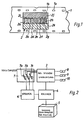
- Fig. 1 denotes a strip of a recording material of conventional manufacture, which has perforation holes 1 a for transport within the recording camera.
- a synthetic test or calibration negative 2 is exposed on a surface 1 b corresponding to a conventional copy template. It contains fields of a gray staircase arranged side by side in the central area, which leads from complete permeability in field 2a to a medium density in the middle field 2a to a field of maximum blackening for 2 hours.
- completely permeable control marks 2 i are arranged on their edge on a certain track, which when measuring this gray staircase each indicate when / the next stage in the scan area located.
- the remaining areas outside the gray staircase 2 j and 2 k are exposed so that the entire area of the calibration template 2 has a medium density and also an approximately neutral color distribution.
- the calibration template 2 is expediently from a central office, e.g. the manufacturer of the respective film, exposed in the manner described and delivered to the processor of the film. There, the film is developed under the conditions there, so that the same conditions exist for the calibration negative and films to be processed later.
- the exposure control device is indicated by 3, the structure of which can roughly correspond to that in DE-PS 2 246 544.
- resistors for transferring the correction values into the exposure time measurement are provided with corresponding actuating devices, which can be controlled via a computer 4.
- the computer 4 is connected on the one hand to a densitometer 5, which has a slot for inserting the copies of the calibration negative 2, and to a memory 6, in which the measured values for the individual color densities of the fields of the gray stairs 2 a to 2 h can be stored.
- These measured values are supplied by the photoelectric arrangement of a densitometer 7, which according to FIG. 3 can be built.
- Three strips of photo receivers 7 a, 7 b and 7 c are indicated purely schematically with a large number of individual elements, one of which can measure the color density values in association with the position of the gray staircase.
- the individual photoelectric receivers 7 a, b, c are sensitized to certain colors by appropriate filters.
- the densitometer 7 is at the same time part of the photoelectric exposure control device and measures the density values of the color originals to be copied and passes them on to the exposure control device 3.
- the amounts of copying light determined by the exposure control device 3 for the individual copies lead to the energization of magnets 8, 9 and 10, each of which actuates a color shutter to terminate a color exposure.
- a light source 12 is arranged as a rod, which illuminates a slit-shaped section of the negatives evenly.
- This section of the negatives is imaged via an objective 13 onto a beam splitter, consisting of two partially transparent mirrors connected in series, of which the first mirror 14 reflects the blue component, but the green and red components allows access to a second mirror 15, which reflects the red portion and passes the green portion.
- the position of the mirror is such that the blue extract of the template just falls on the blue-sensitive bar 7 a of light receivers, while the red extract is shown on the linear light receiver 7 b and the green portion falls unreflected on the green receiver 7 c.
- the scanning of the calibration template only the section of the strips on which the gray staircase 2 a to h is mapped is activated.
- B z indicates the target value for the copy of the corresponding blue extract in the middle field 4.
- the respectively assigned blue values of original and copy are shown by dashed lines with an intersection shown on the blue curve.
- This diagram shows, by plotting the actually measured blue value and the visible deviation from the target value via the lines to the blue curve and the abscissa, which change in the amount of copy light is necessary to achieve the exact target value in the blue field for the next copy.
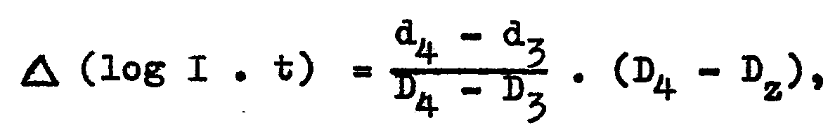
- the densities d with index correspond to the measured density in the corresponding step of the gray scale of the calibration template, while the densities D with index indicate the measured density in the corresponding step of the gray scale copy.
- D z is the target copy density.
- a copy of the calibration template can then be made again for control purposes and this can be measured on the densitometer 5.
- the comparison of the measured values with the respective target values should then lead to the result that the target density values were essentially achieved. Only in the event that the deviations of the measured density values from the target density values when creating the first calibration copy are significantly greater than one step of the gray staircase, can the linear interpolation according to the above equations lead to inaccuracies that require a second calibration step.
- the copier can be calibrated in a single step.
- the described calibration of the copying machine can be used expediently both for the initial calibration of a device and for routine monitoring at more or less large intervals.
- the densitometer 5 and the computer 4 can be combined to form a unit to which a plurality of exposure control devices 3 of copying devices are switchably connected.
- the memory 6 would then have to be assigned to the copier and connected to the computer by a switchable line.
- the blackening curves according to FIG. 4 as the basis for carrying out the arithmetic operation can also be determined in another way than by means of a gray staircase according to FIG. 1.
- different blackening occurs in the individual colors by using previously known different intensities of the copying light, caused by the previously known gradation of the gray wedge.
- the amount of copying light can also be changed by changing the exposure times by known amounts.
- a copy of a known density is a first copy by means of photoelectric exposure control device made.
- a second copy is exposed using a so-called density correction of, for example, one step, ie the exposure time in all three colors is increased linearly by a certain percentage, so that the change in the amount of copy light can be directly related to the change in the copy density.
- density correction of, for example, one step, ie the exposure time in all three colors is increased linearly by a certain percentage, so that the change in the amount of copy light can be directly related to the change in the copy density.
Abstract
Verfahren und Vorrichtung zur Eichung eines Farbkopiergerätes mit fotoelektrischer Belichtungssteuervorrichtung (3), wobei eine Grautreppe mit Stufen bekannter Dichteabstufung und Farbzusammensetzung mit einer durch die fotoelektrische Belichtungssteuervorrichtung bestimmten, für die Erzielung bestimmter Kopiedichtewerte voraussichtlich zutreffenden Kopierlichtmenge aufbelichtet wird. Nach der Entwicklung wird die Grautreppenkopie ausgemessen und die Meßwerte mit den angestrebten Dichtewerten verglichen. Aus den Differenzbeträgen dieser Dichtewerte wird die erforderliche Änderung der Kopierlichtmengen errechnet und die fotoelektrische Belichtungssteuervorrichtung dementsprechend justiert.Method and device for calibrating a color copying machine with a photoelectric exposure control device (3), wherein a gray staircase with steps of known density gradation and color composition is exposed with a copy light quantity determined by the photoelectric exposure control device and likely to be used to achieve certain copy density values. After the development, the gray staircase copy is measured and the measured values are compared with the target density values. The required change in the amounts of copying light is calculated from the difference amounts of these density values and the photoelectric exposure control device is adjusted accordingly.
Description
Die Erfindung betrifft ein Verfahren und eine Vorrichtung zur Eichung eines Farbkopiergerätes mit einer fotoelektrischen Farbbelichtungssteuervorrichtung aufgrund der MeBergebnisse von Testkopien, die von einer Eichvorlage mit vorgegebenen Kopierlichtmengen in den drei Grundfarben belichtet werden.The invention relates to a method and a device for calibrating a color copying machine with a photoelectric color exposure control device on the basis of the measurement results of test copies which are exposed by a calibration original with predetermined amounts of copying light in the three primary colors.
Es wurde bereits bisher so verfahren, daß von einer Eichvorlage mittlerer Dichte mittels der fotoelektrischen Farbbelichtungssteuervorrichtung eine Eichkopie erstellt wurde. Die entwickelte Kopie wurde beurteilt und es wurden empirisch die Korrekturen angegeben, die voraussichtlich zum Erzielen einer befriedigenden Korrektur nötig waren. Mit diesen Korrekturen wurde dann der Kopiervorgang des Eichnegativs wiederholt und wenn diese Korrekturen zu einem positiven Ergebnis geführt hatten, wurden diese Korrekturwerte als Änderung der Empfindlichkeit der fotoelektrischen Belichtungssteuervorrichtung in die entsprechenden Speicherpotentiometer übernommen (s. DE-PS 2 246 544).It has been done so far that a calibration copy was made from a medium-density calibration template by means of the photoelectric color exposure control device. The developed copy was evaluated and the corrections that were expected to be necessary to achieve a satisfactory correction were empirically given. With these corrections the copying process of the calibration negative was then repeated and if these corrections had led to a positive result, these correction values were used as a change in the sensitivity of the photoelectric Exposure control device adopted in the corresponding storage potentiometer (see DE-PS 2 246 544).
Dieses Verfahren hatte den Nachteil, daß verschiedene Schritte erforderlich waren, deren Ergebnis auf der subjektiven Beurteilung der Kopie und der erforderlichen Korrekturwerte beruht, so daß u.U. mehrere Schritte notwendig waren, um die richtige Einstellung des Kopiergerätes zu erreichen.This method had the disadvantage that various steps were necessary, the result of which is based on the subjective assessment of the copy and the required correction values, so that under certain circumstances Several steps were necessary to achieve the correct setting of the copier.
Aufgabe der Erfindung ist es, ein Eichverfahren zu schaffen, das aufgrund objektiver Messung ohne die Notwendigkeit besonderer Erfahrung die richtige Eichung eines Kopiergerätes in aller Regel in einem Schritt ermöglicht.The object of the invention is to provide a calibration method which, based on objective measurement without the need for special experience, generally enables the correct calibration of a copying machine in one step.
Diese Aufgabe wird gelöst durch die in dem Anspruch 1 beschriebene Erfindung.This object is achieved by the invention described in claim 1.
Das erfindungsgemäße Verfahren geht aus von einer synthetischen Eichvorlage. Diese umfaßt z.B. eine siebenstufige Grautreppe, von der die vierte Stufe z.B. auf eine mittlere Dichte von 0,7 belichtet ist. Außerdem ist die Farbe der Grautreppe so gewählt, daß in allen sieben Abschnitten der Grautreppe alle drei Grundfarbenanteile noch gut reproduzierbar meßbar sind. Die Ausmessung der entwickelten Grauflächen dieses Negativs auf einem bestimmten Aufnahmematerial liefert eine für dieses Material kennzeichnende sensitometrische Kurve.The method according to the invention is based on a synthetic calibration template. This includes, for example, a seven-step gray staircase, of which the fourth step is exposed to an average density of 0.7, for example. In addition, the color of the gray staircase is chosen so that in all seven sections of the gray staircase all three basic color components can still be measured in a reproducible manner. The measurement of the developed gray areas of this negative on a specific recording material provides a sensitometric curve which is characteristic of this material.
Wird nun diese insgesamt eine mittlere Dichte aufweisende Eichvorlage mittels der fotoelektrischen Belichtungsssteuervorrichtung des Kopiergerätes auf ein übliches Kopiermaterial aufkopiert, so lassen sich die auf diese Weise erzielten Kopien der einzelnen Grautreppenflächen mit den jeweiligen Farbanteilen den Meßwerten der Eichvorlage gegenüberstellen. Wird mit der Eichvorlage zugleich angegeben, bei welchem Kopiedichtewert eines bestimmten Feldes der Grautreppe insgesamt befriedigende Kopien erreicht werden, so ist es möglich, die erforderlichen Änderungen der Kopierlichtmenge für das betreffende Feld der ,mit guter Näherung, Grautreppe zu errechnen. Die auf diese Weise errechneten Änderungen der Kopierlichtmenge lassen sich dann exakt in die Belichtungssteuervorrichtung übertragen, so daß in aller Regel schon mit einem einzigen Eichschritt eine richtige Einstellung des Kopiergerätes erzielt wird.If this calibration template, which has an overall average density, is now copied onto a conventional copying material by means of the photoelectric exposure control device of the copying machine, the copies of the individual gray staircase surfaces obtained in this way can be compared with the measured values of the calibration template with the respective color components. If, at the same time, the calibration template specifies at which copy density value of a certain field of the gray staircase satisfactory copies are achieved, it is possible to calculate the necessary changes in the amount of copying light for the field concerned, with good approximation, the gray staircase. The changes in the amount of copying light calculated in this way can then be transferred exactly into the exposure control device, so that, as a rule, a correct setting of the copying machine is achieved with a single calibration step.
Weitere Einzelheiten und Vorteile des vorgeschlagenen Verfahrens, sowie einer Vorrichtung zu seiner Durchführung, ergeben sich aus den Unteransprüchen im Zusammenhang mit der Beschreibung eines bevorzugten Ausführungsbeispiels, das anhand der Figuren eingehend erläutert ist. Es zeigen:
- Fig. 1 schematisch den Aufbau einer Eichvorlage,
- Fig. 2 ein Blockschaltbild zur Auswertung von Eichvorlage und Kopie derselben zur Eichung der Belichtungssteuervorrichtung,
- Fig. 3 das Densitometer zur Messung der Vorlagendichten und
- Fig. 4 ein Diagramm mit einer Übergangsfunktion von der Negativdichte zur Kopiedichte.
- 1 schematically shows the structure of a calibration template,
- 2 is a block diagram for evaluating the calibration template and a copy thereof for calibrating the exposure control device,
- Fig. 3 shows the densitometer for measuring the original densities and
- Fig. 4 is a diagram with a transition function from the negative density to the copy density.
In Fig. 1 ist mit 1 ein Streifen eines Aufnahmematerials üblicher Konfektionierung bezeichnet, der Perforationslöcher 1 a zum Transport innerhalb der Aufnahmekamera aufweist. Auf einer einer üblichen Kopiervorlage entsprechenden Fläche 1 b ist ein synthetisches Test- oder Eichnegativ 2 aufbelichtet. Es enthält im Mittelbereich nebeneinander angeordnete Felder einer Grautreppe, die von völliger Durchlässigkeit im Feld 2 a zu einer mittleren Dichte im mittleren Feld 2 e bis zu einem Feld maximaler Schwärzung 2 h führt. Jeweils in räumlicher Zuordnung zu den Feldern der Grautreppe 2 a bis 2 h sind an deren Rand auf einer bestimmten Spur vollständig durchlässige Steuermarken 2 i angeordnet, die bei der Ausmessung dieser Grau- treppe jeweils anzeigen, wenn/die nächste Stufe im Abtastbereich befindet. Die verbleibenden Flächen außerhalb der Grautreppe 2 j und 2 k sind so belichtet, daß der gesamte Bereich der Eichvorlage 2 eine mittlere Dichte und auch eine ungefähr neutrale Farbverteilung aufweist.In Fig. 1, 1 denotes a strip of a recording material of conventional manufacture, which has
Die Eichvorlage 2 wird zweckmäßigerweise von einer Zentralstelle, z.B. dem Hersteller des jeweiligen Films, in der beschriebenen Weise belichtet und an den Verarbeiter des Films geliefert. Dort wird der Film unter den dort vorhandenen Bedingungen entwickelt, so daß insoweit gleiche Bedingungen für das Eichnegativ und später zu bearbeitende Filme vorliegen.The
In dem Blockschaltbild gemäß Figur 2 ist mit 3 die Belichtungssteuervorrichtung angegeben, die in ihrem Aufbau etwa der in der DE-PS 2 246 544 entsprechen kann. Ergänzend sind dabei allerdings Widerstände zum Übernehmen der Korrekturwerte in die Belichtungszeitbemessung mit entsprechenden Stelleinrichtungen versehen, die über einen Rechner 4 angesteuert werden können. Der Rechner 4 ist einerseits verbunden mit einem Densitometer 5, das einen Schlitz zum Einführen der Kopien des Eichnegativs 2 aufweist, sowie mit einem Speicher 6, in dem die Meßwerte für die einzelnen Farbdichten der Felder der Grautreppe 2 a bis 2 h gespeichert werden können. Diese Meßwerte werden von der fotoelektrischen Anordnung eines Densitometers 7 geliefert, das gemäß Fig. 3 aufgebaut sein kann. Rein schematisch sind drei Leisten von Fotoempfängern 7 a, 7 b und 7 c mit einer Vielzahl von einzelnen Elementen angedeutet, von denen eines in Zuordnung zur Lage der Grautreppe deren Farbdichtewerte messen kann. Die einzelnen fotoelektrischen Empfänger 7 a, b, c sind durch entsprechende Filter für bestimmte Farben sensibilisiert. Aus Zweckmäßigkeitsgründen ist das Densitometer 7 gleichzeitig Teil der fotoelektrischen Belichtungssteuervorrichtung und mißt die Dichtewerte der zu kopierenden Farbvorlagen und gibt diese an die Belichtungssteuervorrichtung 3 weiter. Die von der Belichtungssteuervorrichtung 3 festgelegten Kopierlichtmengen für die einzelnen Kopiervorlagen führen zur Bestromung von Magneten 8, 9 und 10, die jeweils einen Farbverschluß zur Beendigung einer Farbbelichtung betätigen.In the block diagram according to FIG. 2, the exposure control device is indicated by 3, the structure of which can roughly correspond to that in
In Fig. 3 ist das Densitometer zur Abtastung der Eichvorlage nochmals genauer dargestellt. Über der Bahn 11 für die Filmstreifen, u.a. den Film 1 mit dem Eichnegativ 2, ist eine als Stab ausgebildete Lichtquelle 12 angeordnet, die einen spaltförmigen Abschnitt der Negative gleichmäßig ausleuchtet. Dieser Abschnitt der Negative wird über ein Objektiv 13 abgebildet auf einen Strahlenteiler, bestehend aus zwei hintereinander geschalteten teildurchlässigen Spiegeln, von denen der erste Spiegel 14 den Blauanteil reflektiert, jedoch den grünen und den roten Anteil weiter gelangen läßt auf einen zweiten Spiegel 15, der den roten Anteil reflektiert und den grünen Anteil durchgehen läßt. Die Stellung der Spiegel ist so, daß der Blauauszug der Vorlage gerade auf die blauempfindliche Leiste 7 a von Lichtempfängern fällt, während der Rotauszug auf den linealförmigen Lichtempfänger 7 b abgebildet wird und der Grünanteil unreflektiert auf den Grünempfänger 7 c fällt. Während der Abtastung der Eichvorlage ist jeweils nur der Abschnitt der Leisten aktiviert, auf den die Grautreppe 2 a bis h abgebildet wird.In Fig. 3, the densitometer for scanning the calibration template is shown again in more detail. Above the
In Fig. 4 ist als Diagramm eine Übergangsfunktion dargestellt für den Übergang von den Dichten der Grautreppenabschnitte in der Eichvorlage in die entsprechenden Dichtewerte der Kopie. Die Dichten der Eichvorlage sind für blau mit b angegeben und dem Index des jeweiligen Feldes, für grün mit g und für rot mit r. Die entsprechenden Dichtewerte der Kopie der Grautreppe sind mit großen Buchstaben B, G und R mit den entsprechenden Indices angegeben. Der besseren Übersichtlichkeit des Diagramms wegen sind jedoch hinweisende Bezugslinien nur für die blauen Werte angegeben. Schließlich ist mit Bz der Zielwert für die Kopie des entsprechenden Blauauszuges des mittleren Feldes 4 angegeben. Dazu sind die jeweils einander zugeordneten Blauwerte von Vorlage und Kopie durch gestrichelte Linien mit Schnittpunkt auf der Blaukurve dargestellt. Durch dieses Diagramm ist durch Auftragen des tatsächlich gemessenen Blauwertes und der dadurch sichtbaren Abweichung vom Zielwert über die Linien zur Blaukurve und zur Abszisse feststellbar, welche Änderung in der Kopierlichtmenge notwendig ist, um bei der nächsten Kopie genau den Zielwert im blauen Feld zu erreichen.4 shows a transition function as a diagram for the transition from the densities of the gray staircase sections in the calibration template to the corresponding density values of the copy. The densities of the calibration template are indicated for blue with b and the index of the respective field, for green with g and for red with r. The corresponding density values of the copy of the gray staircase are given in capital letters B, G and R with the corresponding indices. For better clarity of the diagram, however, indicative reference lines are only given for the blue values. Finally, B z indicates the target value for the copy of the corresponding blue extract in the middle field 4. For this purpose, the respectively assigned blue values of original and copy are shown by dashed lines with an intersection shown on the blue curve. This diagram shows, by plotting the actually measured blue value and the visible deviation from the target value via the lines to the blue curve and the abscissa, which change in the amount of copy light is necessary to achieve the exact target value in the blue field for the next copy.
Die Wirkungsweise des erfindungsgemäßen Verfahrens anhand der dargestellten Vorrichtung ist wie folgt:
- Die Farbdichtewerte für jedes der sieben
Felder 2 a bis 2 h der Eichvorlage gemäß Fig. 1 werden mittels des Densitometers gemäß Fig. 3 gemessen und in den Speicher 6 eingebracht. Unmittelbar danach wird durch die Belichtungssteuervorrichtung in ihrem augenblicklichen Zustand automatisch eine Kopie der Eichvorlage erstellt. Diese wird nach ihrer Entwicklung im Densitometer 5 ausgemessen, wobei ebenfalls für jede Stufe der Grautreppe in der Kopie die drei Dichtewerte in den einzelnen Farben, bezeichnet mit den großen Buchstaben Bu, Gv und Rw gemessen und dem Rechner 4 zugeleitet werden. Für den Fall der richtigen Einstellung des Gerätes fallen die drei Farbdichtewerte des mittleren Grautreppenfeldes in der Kopie mit den jeweiligen Zielwerten Bz, Gz und Rz zusammen. Fallen die gemessenen Werte nicht mit den Zielwerten zusammen, ist eine Nachjustierung der Kopiervorrichtung erforderlich, d.h. die Belichtungssteuervorrichtung muß in ihrer Empfindlichkeit auf Meßlicht so abgeändert werden, daß die geänderte Kopierlichtmenge gerade zum Erreichen der Zieldichten in der mittleren Stufe der Grautreppenkopie führt.
- The color density values for each of the seven
fields 2a to 2h of the calibration template according to FIG. 1 are measured by means of the densitometer according to FIG. 3 and introduced into the memory 6. Immediately afterwards, the exposure control device automatically creates a copy of the calibration document in its current state. This is measured after it has been developed in densitometer 5, the three density values in the individual colors, denoted by the capital letters B u , G v and R w , likewise being measured in the copy for each step of the gray staircase and sent to computer 4. If the device is set correctly, the three color density values of the middle gray staircase field in the copy coincide with the respective target values B z , G z and R z . If the measured values do not fall with the Together, target values require readjustment of the copying device, ie the exposure control device must be modified in its sensitivity to measuring light in such a way that the changed amount of copying light just leads to the target densities being reached in the middle stage of the gray staircase copy.
Im Idealfall, wenn sich die einzelnen Farbbelichtungen nicht gegenseitig beeinflussen, erfolgt dies nach folgender Gleichung:
Die Dichten d mit Index entsprechen der gemessenen Dichte in der entsprechenden Stufe der Grautreppe der Eichvorlage, während die Dichten D mit Index die gemessene Dichte in der entsprechenden Stufe der Grautreppenkopie angeben. Dz ist die angestrebte Kopiedichte.The densities d with index correspond to the measured density in the corresponding step of the gray scale of the calibration template, while the densities D with index indicate the measured density in the corresponding step of the gray scale copy. D z is the target copy density.
In aller Regel trifft diese Voraussetzung jedoch nicht zu, da die Filter vor den Meßelementen, die sensitometrischen Eigenschaften des Films und die Kopierfilter nicht in idealer Weise übereinstimmen. In diesem Fall ergeben sich die Änderungen der Kopierlichtmengen nach folgenden Gleichungen:As a rule, however, this requirement does not apply, since the filters in front of the measuring elements, the sensitometric properties of the film and the copying filters do not match in an ideal way. In this case, the changes in the amount of copy light result from the following equations:
![]()
![]()
![]()

![]()
![]()
![]()
![]()

![]()
![]()
![]()
![]()

![]()
![]()
![]()
![]()
- wobei bu, gv und rw die Farbdichte des betreffenden Grautreppenfeldes in der Eichvorlage angibt,
- Bu, Gv und R die Farbdichten in den betreffenden Stufen der Grautreppenkopie und
- Bz, Gz und Rz die angestrebten Farbdichten des mittleren Feldes 4 der Grautreppenkopie bedeuten.
- where bu , g v and r w indicate the color density of the relevant gray staircase field in the calibration template,
- B u , G v and R are the color densities in the relevant levels of the gray staircase copy and
- B z , G z and R z mean the desired color densities of the middle field 4 of the gray staircase copy.
Diese Rechenoperationen werden im Rechner 4 ausgeführt und die ermittelten Änderungen der Kopierlichtmengen werden direkt in die entsprechenden Potentiometer der Belichtungssteuervorrichtung nach DE-PS 2 246 544 übernommen.These arithmetic operations are carried out in the computer 4 and the determined changes in the amounts of copying light are taken directly into the corresponding potentiometers of the exposure control device according to
Zu Kontrollzwecken kann dann nochmals eine Kopie der Eichvorlage erstellt und diese auf dem Densitometer 5 ausgemessen werden. Der Vergleich der gemessenen Werte mit den jeweiligen Zielwerten müßte dann zum Ergebnis führen, daß die Zieldichtewerte im wesentlichen erreicht wurden. Nur für den Fall, daß die Abweichungen der gemessenen Dichtewerte von den Zieldichtewerten bei Erstellung der ersten Eichkopie deutlich größer als eine Stufe der Grautreppe sind, kann die lineare Interpolation gemäß den obengenannten Gleichungen zu Ungenauigkeiten führen, die noch einen zweiten Eichschritt erforderlich machen. Durch Annäherung der Kurven gemäß Figur 4 durch ein Polynom zweiten oder dritten Grades und mit erhöhtem Rechenaufwand läßt sich auch in diesen Fällen eine Eichung des Kopiergerätes mit einem einzigen Schritt erreichen.A copy of the calibration template can then be made again for control purposes and this can be measured on the densitometer 5. The comparison of the measured values with the respective target values should then lead to the result that the target density values were essentially achieved. Only in the event that the deviations of the measured density values from the target density values when creating the first calibration copy are significantly greater than one step of the gray staircase, can the linear interpolation according to the above equations lead to inaccuracies that require a second calibration step. By approximating the curves according to FIG. 4 by means of a second or third degree polynomial and with increased computational effort, one can also use them In some cases, the copier can be calibrated in a single step.
Die beschriebene Eichung des Kopiergerätes läßt sich sowohl für die Ersteichung eines Gerätes als auch für die routinemäßige Überwachung in mehr oder minder großen Zeitabständen zweckmäßig anwenden. Dabei können das Densitometer 5 und der Rechner 4 zu einer Einheit zusammengefügt sein, an die umschaltbar mehrere Belichtungssteuervorrichtungen 3 von Kopiergeräten angeschlossen sind. Bei einem Aufbau gemäß Figur 2 müßte dann der Speicher 6 dem Kopiergerät zugeordnet und durch eine umschaltbare Leitung mit dem Rechner verbunden sein.The described calibration of the copying machine can be used expediently both for the initial calibration of a device and for routine monitoring at more or less large intervals. In this case, the densitometer 5 and the computer 4 can be combined to form a unit to which a plurality of
Die Schwärzungskurven gemäß Figur 4 als Grundlage für die Durchführung der Rechenoperation lassen sich auch noch auf andere Weise als mittels einer Grautreppe gemäß Figur 1 ermitteln. Dort geschieht die Erzeugung unterschiedlicher Schwärzungen in den einzelnen Farben durch Anwendung vorbekannt unterschiedlicher Intensitäten des Kopierlichtes, hervorgerufen durch die vorbekannte Abstufung des Graukeils. Anstelle der durch Intensitätsänderung veränderten Kopierlichtmengen kann auch durch Änderung der Belichtungszeiten um vorbekannte Beträge die Kopierlichtmenge verändert werden. Zu diesem Zweck wird von einer Kopiervorlage bekannter Dichte eine erste kopie mittels der fotoelektrischen Belichtungssteuervorrichtung gemacht. Daran anschließend wird eine zweite Kopie belichtet unter Anwendung einer sogenannten Dichtekorrektur von z.B. einer Stufe, d.h. die Belichtungszeit in allen drei Farben wird linear um einen bestimmten Prozentsatz erhöht, so daß die Änderung der Kopierlichtmenge direkt ins Verhältnis gesetzt werden kann zu der Änderung der Kopiedichte. Dies läßt eindeutige Schlüsse auf die Neigung der Schwärzungskurven in einem bestimmten Dichtebereich zu. Da nun erfahrungsgemäß die Schwärzungskurven der üblicherweise verwendeten Kopiermaterialien im wesentlichen alle sehr ähnlich verlaufen, ist aufgrund dieser Angaben über die Steilheit der Schwärzungskurve und die ungefähre Lage eines Punktes davon - gegeben durch die Dichte der Eichvorlage und deren durch die Belichtungssteuervorrichtung gesteuerte erste Kopie - die Festlegung von Parametern möglich, die bei sonst gleicher Kurvengestalt die unterschiedlichen Ausbildungen der Schwärzungskurven angeben. Eine solche Näherung durch eine mathematische Funktion dieser Schwärzungskurven ist z.B. im unteren Durchhangbereich durch eine E-Fuaktion und in dem daran anschließenden annähernd linearen Bereich durch eine Gerade mit hinreichender Genauigkeit möglich. Diese Funktionen sind dann in das Rechenprogramm des Rechners 4 eingegeben, so daß aufgrund der Meßwerte die Parameter für die genaue Kurvenform errechnet und daraus die erforderliche Veränderung der Einstellung der Belichtungssteuervorrichtung ermittelt werden können.The blackening curves according to FIG. 4 as the basis for carrying out the arithmetic operation can also be determined in another way than by means of a gray staircase according to FIG. 1. There, different blackening occurs in the individual colors by using previously known different intensities of the copying light, caused by the previously known gradation of the gray wedge. Instead of the amount of copying light changed by changing the intensity, the amount of copying light can also be changed by changing the exposure times by known amounts. For this purpose, a copy of a known density is a first copy by means of photoelectric exposure control device made. Then a second copy is exposed using a so-called density correction of, for example, one step, ie the exposure time in all three colors is increased linearly by a certain percentage, so that the change in the amount of copy light can be directly related to the change in the copy density. This allows clear conclusions to be drawn about the slope of the density curves in a certain density range. Since experience has shown that the blackening curves of the commonly used copying materials are essentially all very similar, the information on the steepness of the blackening curve and the approximate position of a point thereof - given by the density of the calibration document and its first copy controlled by the exposure control device - is used to determine this of parameters possible which, with otherwise the same curve shape, indicate the different configurations of the blackening curves. Such an approximation by means of a mathematical function of these blackening curves is possible, for example, in the lower sag region by an e-foot action and in the adjoining approximately linear region by a straight line with sufficient accuracy. These functions are then entered into the computer program of the computer 4, so that the parameters for the precise curve shape can be calculated on the basis of the measured values and the required change in the setting of the exposure control device can be determined therefrom.
Claims (9)
dadurch gekennzeichnet, daß die Eichvorlage mit einer durch die fotoelektrische Belichtungssteuervorrichtung bestimmten, für die Erzielung bestimmter Kopiedichtewerte voraussichtlich zutreffenden Kopierlichtmenge auf das Kopiermaterial aufbelichtet wird, daß die entwickelten Eichvorlagenkopien in eine mit dem Kopiergerät verbundene Dichtemeßeinrichtung eingegeben werden und aus der Differenz der gemessenen und der angestrebten Dichtewerte die erforderliche Änderung der Kopierlichtmengen errechnet und die fotoelektrische belichtungssteuervorrichtung automatisch justiert wird.1. Method for calibrating a color copying machine with a photoelectric color exposure control device on the basis of the measurement results of test copies which are exposed by a calibration original with predetermined amounts of copying light in the three primary colors.
characterized in that the calibration template is exposed onto the copy material with a copy light quantity determined by the photoelectric exposure control device and likely to achieve certain copy density values, that the developed template copies are input into a density measuring device connected to the copier and from the difference between the measured and the aimed Density values the required change in the amount of copying light is calculated and the photoelectric exposure control device is automatically adjusted.


Applications Claiming Priority (2)
| Application Number | Priority Date | Filing Date | Title |
|---|---|---|---|
| DE19792911566 DE2911566A1 (en) | 1979-03-23 | 1979-03-23 | METHOD AND DEVICE FOR CALIBRATING A COLOR COPIER |
| DE2911566 | 1979-03-23 |
Publications (2)
| Publication Number | Publication Date |
|---|---|
| EP0020855A1 true EP0020855A1 (en) | 1981-01-07 |
| EP0020855B1 EP0020855B1 (en) | 1983-03-09 |
Family
ID=6066286
Family Applications (1)
| Application Number | Title | Priority Date | Filing Date |
|---|---|---|---|
| EP80101076A Expired EP0020855B1 (en) | 1979-03-23 | 1980-03-04 | Method and apparatus for calibrating a colour copying apparatus |
Country Status (4)
| Country | Link |
|---|---|
| US (1) | US4464045A (en) |
| EP (1) | EP0020855B1 (en) |
| JP (1) | JPS55127581A (en) |
| DE (1) | DE2911566A1 (en) |
Cited By (6)
| Publication number | Priority date | Publication date | Assignee | Title |
|---|---|---|---|---|
| EP0119941A2 (en) * | 1983-03-22 | 1984-09-26 | HOPE INDUSTRIES, Inc. | A color printing control system and method |
| FR2543317A1 (en) * | 1983-03-24 | 1984-09-28 | Noritsu Kenkyu Center Co | METHOD FOR DETERMINING THE OPTIMAL CONDITIONS OF EXPOSURE FOR A COLOR PRINTER |
| EP0159253A1 (en) * | 1984-03-30 | 1985-10-23 | Marc Bernheim | Method for standardizing a photocopier |
| WO1986002175A1 (en) * | 1984-10-01 | 1986-04-10 | Durst Phototechnik Gmbh | Process and device for calibrating a photographic colour enlargement or copying machine |
| EP0250177A1 (en) * | 1986-06-20 | 1987-12-23 | Britax Wingard Limited | Exterior rear-view mirror for a motor vehicle |
| US6222612B1 (en) | 1996-06-14 | 2001-04-24 | Agfa-Gevaert Ag | Process and device for the output of electronic image signals, and a photographic copier |
Families Citing this family (25)
| Publication number | Priority date | Publication date | Assignee | Title |
|---|---|---|---|---|
| US4540276A (en) * | 1982-03-29 | 1985-09-10 | Ost Clarence S | Color photographic reproduction system |
| GB2123968B (en) * | 1982-06-10 | 1986-01-29 | Konishiroku Photo Ind | Color printer |
| JPS5983144A (en) * | 1982-11-02 | 1984-05-14 | Fuji Photo Film Co Ltd | Method for correcting photometric condition of photographic film |
| US4603969A (en) * | 1984-02-06 | 1986-08-05 | Fuji Photo Film Co., Ltd. | Method for setting conditions in photographic printing |
| US4707118A (en) * | 1984-03-13 | 1987-11-17 | Fuji Photo Film Co., Ltd. | Method for controlling exposure in color photographic printers |
| DE3412881A1 (en) * | 1984-04-05 | 1985-10-17 | Agfa-Gevaert Ag, 5090 Leverkusen | METHOD FOR COPYING COLORED DOCUMENTS |
| DE3437069A1 (en) * | 1984-10-09 | 1986-04-10 | Agfa-Gevaert Ag, 5090 Leverkusen | METHOD AND DEVICE FOR PRODUCING COPIES OF COLOR DOCUMENTS DIFFICULT TO COPY |
| JPH0640194B2 (en) * | 1985-10-15 | 1994-05-25 | 富士写真フイルム株式会社 | How to set and manage photo printing conditions |
| FR2602596A1 (en) * | 1986-08-06 | 1988-02-12 | Kis Photo Ind | Test negative film for calibrating a machine for printing photographic films, and method for implementation thereof |
| JPS63172181A (en) * | 1987-01-12 | 1988-07-15 | Ricoh Co Ltd | Color balance adjusting device for color copying machine |
| US4774548A (en) * | 1987-06-12 | 1988-09-27 | Eastman Kodak Company | Photographic printer including integral reflection densitometry apparatus |
| JPH03500338A (en) * | 1987-10-01 | 1991-01-24 | イーストマン・コダック・カンパニー | System for calibration and control of photo color printers |
| US4774551A (en) * | 1987-11-19 | 1988-09-27 | Eastman Kodak Company | Photographic printer |
| GB9013087D0 (en) * | 1990-06-12 | 1990-08-01 | Gan Chiu L | Photographic exposure control |
| DE4031022A1 (en) * | 1990-10-01 | 1992-04-02 | Agfa Gevaert Ag | METHOD FOR PRODUCING COPIES OF STRIP-SHAPED COPY DOCUMENTS AND RELATED DEVICE |
| US6985270B1 (en) | 2000-08-09 | 2006-01-10 | Eastman Kodak Company | Method and photographic element for calibrating digital images |
| US6284445B1 (en) | 2000-08-09 | 2001-09-04 | Eastman Kodak Company | Reference calibration patch arrangement to minimize exposure and measurement artifacts and maximize robustness to defects |
| US6280914B1 (en) | 2000-08-09 | 2001-08-28 | Eastman Kodak Company | Photographic element with reference calibration data |
| US6866199B1 (en) | 2000-08-09 | 2005-03-15 | Eastman Kodak Company | Method of locating a calibration patch in a reference calibration target |
| US7113627B1 (en) | 2000-08-09 | 2006-09-26 | Eastman Kodak Company | Location of extended linear defects |
| US6456798B1 (en) | 2000-08-09 | 2002-09-24 | Eastman Kodak Company | Barcode and data storage arrangement on a photographic element |
| DE10234140A1 (en) * | 2002-07-26 | 2004-02-05 | Arnold & Richter Cine Technik Gmbh & Co Betriebs Kg | Test device and test method |
| US20070177229A1 (en) * | 2006-01-30 | 2007-08-02 | Gianni Cessel | Imaging device calibration system and method |
| EP2407134A1 (en) | 2010-07-15 | 2012-01-18 | The Procter & Gamble Company | Absorbent core |
| CN114905851B (en) * | 2022-07-15 | 2022-11-11 | 浙江工业大学 | Method for collecting characteristic curve of printing color density |
Citations (7)
| Publication number | Priority date | Publication date | Assignee | Title |
|---|---|---|---|---|
| DE1597047B2 (en) * | 1967-04-26 | 1973-08-09 | Agfa Gevaert AG, 5090 Leverkusen | METHOD OF CONTROLLING THE EXPOSURE OF A COPY MATERIAL |
| DE2356277A1 (en) * | 1973-11-10 | 1975-05-22 | Agfa Gevaert Ag | METHOD OF DETERMINING THE EXPOSURE TIME OF A PHOTOGRAPHIC COPY MATERIAL AND DEVICE FOR CARRYING OUT THE METHOD |
| DE2246544B2 (en) * | 1972-09-22 | 1977-03-24 | Agfa-Gevaert Ag, 5090 Leverkusen | METHOD AND DEVICE FOR ADJUSTING A PHOTOGRAPHIC COLOR COPIER |
| US4087180A (en) * | 1977-01-28 | 1978-05-02 | Dinatale Robert F | Photographic printing method |
| DE2803381A1 (en) * | 1978-01-26 | 1979-08-02 | Agfa Gevaert Ag | METHOD AND DEVICE FOR DETERMINING EXPOSURE VALUES FOR COPYING COLOR MASTERS |
| US4167327A (en) * | 1978-03-22 | 1979-09-11 | Dinatale Robert F | Photographic printing method |
| US4174173A (en) * | 1977-11-04 | 1979-11-13 | Pako Corporation | Photographic printer with interactive color balancing |
Family Cites Families (4)
| Publication number | Priority date | Publication date | Assignee | Title |
|---|---|---|---|---|
| DE1035475B (en) * | 1956-08-04 | 1958-07-31 | Hell Rudolf Dr Ing Fa | Electronic process and electronic device for negative-positive reversal and for correcting the course of the gradation curves of the photographic color extracts of a multicolored image to be reproduced |
| US3120782A (en) * | 1961-03-27 | 1964-02-11 | Eastman Kodak Co | Exposure control system for color printers |
| US3799668A (en) * | 1973-03-12 | 1974-03-26 | Xerox Corp | Color standard and method of calibrating a multi-color electrophotographic printing machine |
| CH627288A5 (en) * | 1977-03-11 | 1981-12-31 | Gretag Ag |
-
1979
- 1979-03-23 DE DE19792911566 patent/DE2911566A1/en active Granted
-
1980
- 1980-03-04 EP EP80101076A patent/EP0020855B1/en not_active Expired
- 1980-03-21 JP JP3483180A patent/JPS55127581A/en active Granted
-
1982
- 1982-06-07 US US06/385,923 patent/US4464045A/en not_active Expired - Fee Related
Patent Citations (7)
| Publication number | Priority date | Publication date | Assignee | Title |
|---|---|---|---|---|
| DE1597047B2 (en) * | 1967-04-26 | 1973-08-09 | Agfa Gevaert AG, 5090 Leverkusen | METHOD OF CONTROLLING THE EXPOSURE OF A COPY MATERIAL |
| DE2246544B2 (en) * | 1972-09-22 | 1977-03-24 | Agfa-Gevaert Ag, 5090 Leverkusen | METHOD AND DEVICE FOR ADJUSTING A PHOTOGRAPHIC COLOR COPIER |
| DE2356277A1 (en) * | 1973-11-10 | 1975-05-22 | Agfa Gevaert Ag | METHOD OF DETERMINING THE EXPOSURE TIME OF A PHOTOGRAPHIC COPY MATERIAL AND DEVICE FOR CARRYING OUT THE METHOD |
| US4087180A (en) * | 1977-01-28 | 1978-05-02 | Dinatale Robert F | Photographic printing method |
| US4174173A (en) * | 1977-11-04 | 1979-11-13 | Pako Corporation | Photographic printer with interactive color balancing |
| DE2803381A1 (en) * | 1978-01-26 | 1979-08-02 | Agfa Gevaert Ag | METHOD AND DEVICE FOR DETERMINING EXPOSURE VALUES FOR COPYING COLOR MASTERS |
| US4167327A (en) * | 1978-03-22 | 1979-09-11 | Dinatale Robert F | Photographic printing method |
Cited By (7)
| Publication number | Priority date | Publication date | Assignee | Title |
|---|---|---|---|---|
| EP0119941A2 (en) * | 1983-03-22 | 1984-09-26 | HOPE INDUSTRIES, Inc. | A color printing control system and method |
| EP0119941A3 (en) * | 1983-03-22 | 1987-07-15 | HOPE INDUSTRIES, Inc. | A color printing control system and method |
| FR2543317A1 (en) * | 1983-03-24 | 1984-09-28 | Noritsu Kenkyu Center Co | METHOD FOR DETERMINING THE OPTIMAL CONDITIONS OF EXPOSURE FOR A COLOR PRINTER |
| EP0159253A1 (en) * | 1984-03-30 | 1985-10-23 | Marc Bernheim | Method for standardizing a photocopier |
| WO1986002175A1 (en) * | 1984-10-01 | 1986-04-10 | Durst Phototechnik Gmbh | Process and device for calibrating a photographic colour enlargement or copying machine |
| EP0250177A1 (en) * | 1986-06-20 | 1987-12-23 | Britax Wingard Limited | Exterior rear-view mirror for a motor vehicle |
| US6222612B1 (en) | 1996-06-14 | 2001-04-24 | Agfa-Gevaert Ag | Process and device for the output of electronic image signals, and a photographic copier |
Also Published As
| Publication number | Publication date |
|---|---|
| US4464045A (en) | 1984-08-07 |
| JPS6339908B2 (en) | 1988-08-08 |
| EP0020855B1 (en) | 1983-03-09 |
| JPS55127581A (en) | 1980-10-02 |
| DE2911566C2 (en) | 1987-03-12 |
| DE2911566A1 (en) | 1980-10-02 |
Similar Documents
| Publication | Publication Date | Title |
|---|---|---|
| EP0020855B1 (en) | Method and apparatus for calibrating a colour copying apparatus | |
| EP0003310B1 (en) | Method and apparatus for determining the quantities of light necessary for photographic colour printing | |
| EP0025078B1 (en) | Method and apparatus for controlling the working condition of a copying apparatus and the subsequent developing apparatus | |
| EP0475897B1 (en) | Method for producing photographic colour copies | |
| DE2342414B2 (en) | Method for determining the exposure when making copies from a negative image strip | |
| DE1957752B2 (en) | Method and device for determining exposure values | |
| DE3210615A1 (en) | METHOD FOR CONTROLLING THE COPY CONDITIONS OF A COLOR NEGATIVE | |
| EP0128349B1 (en) | Method of determining the printing light quantity of the singular primary colours in colour printing | |
| CH664633A5 (en) | METHOD FOR PERCEPING AN ABNORMAL PHOTOORIGINAL. | |
| DE3931700C2 (en) | Method for determining the amount of exposure in a photographic printing machine | |
| DE3426350C2 (en) | ||
| DE2840287C2 (en) | ||
| DE2406191C2 (en) | Method of controlling exposure in the production of photographic copies | |
| DE4239315C1 (en) | Image generation on photographic colour copier material - processing digital image signals before recording in colour, and determining colour purity | |
| DE3412641A1 (en) | COLOR ANALYZER | |
| DE3048729A1 (en) | METHOD AND DEVICE FOR AUTOMATIC EXPOSURE CONTROL IN A PHOTOGRAPHIC COLOR COPIER | |
| DE3117334C2 (en) | ||
| DE2459456A1 (en) | Exposure control during copying of colour photographs - density of original scanned by points in three primary colours | |
| EP0197076B1 (en) | Photographic enlarger or copying machine for colour prints | |
| EP0197093B1 (en) | Process and device for calibrating a photographic colour enlargement or copying machine | |
| DE2732430C2 (en) | Method and device for analyzing a reproduction original | |
| EP0825481B1 (en) | Process for making photographic copies from photographic originals | |
| DE4323630C2 (en) | Correction method and correction device for a photocopier | |
| DE19539736C2 (en) | Method and device for compensating color casts in the production of index prints | |
| EP0261074B1 (en) | Method to determine the exposing values in the copying of slides on reversible material |
Legal Events
| Date | Code | Title | Description |
|---|---|---|---|
| PUAI | Public reference made under article 153(3) epc to a published international application that has entered the european phase |
Free format text: ORIGINAL CODE: 0009012 |
|
| AK | Designated contracting states |
Designated state(s): BE CH FR GB IT NL |
|
| 17P | Request for examination filed |
Effective date: 19801215 |
|
| ITF | It: translation for a ep patent filed |
Owner name: ING. C. GREGORJ S.P.A. |
|
| GRAA | (expected) grant |
Free format text: ORIGINAL CODE: 0009210 |
|
| AK | Designated contracting states |
Designated state(s): BE CH FR GB IT NL |
|
| ET | Fr: translation filed | ||
| ITTA | It: last paid annual fee | ||
| PGFP | Annual fee paid to national office [announced via postgrant information from national office to epo] |
Ref country code: BE Payment date: 19941215 Year of fee payment: 16 |
|
| PGFP | Annual fee paid to national office [announced via postgrant information from national office to epo] |
Ref country code: GB Payment date: 19950222 Year of fee payment: 16 |
|
| PGFP | Annual fee paid to national office [announced via postgrant information from national office to epo] |
Ref country code: CH Payment date: 19950224 Year of fee payment: 16 |
|
| PGFP | Annual fee paid to national office [announced via postgrant information from national office to epo] |
Ref country code: FR Payment date: 19950307 Year of fee payment: 16 |
|
| PGFP | Annual fee paid to national office [announced via postgrant information from national office to epo] |
Ref country code: NL Payment date: 19950331 Year of fee payment: 16 |
|
| PG25 | Lapsed in a contracting state [announced via postgrant information from national office to epo] |
Ref country code: GB Effective date: 19960304 |
|
| PG25 | Lapsed in a contracting state [announced via postgrant information from national office to epo] |
Ref country code: BE Effective date: 19960331 Ref country code: CH Effective date: 19960331 |
|
| BERE | Be: lapsed |
Owner name: AGFA-GEVAERT A.G. Effective date: 19960331 |
|
| PG25 | Lapsed in a contracting state [announced via postgrant information from national office to epo] |
Ref country code: NL Effective date: 19961001 |
|
| GBPC | Gb: european patent ceased through non-payment of renewal fee |
Effective date: 19960304 |
|
| REG | Reference to a national code |
Ref country code: CH Ref legal event code: PL |
|
| PG25 | Lapsed in a contracting state [announced via postgrant information from national office to epo] |
Ref country code: FR Effective date: 19961129 |
|
| NLV4 | Nl: lapsed or anulled due to non-payment of the annual fee |
Effective date: 19961001 |
|
| REG | Reference to a national code |
Ref country code: FR Ref legal event code: ST |
|
| PLBE | No opposition filed within time limit |
Free format text: ORIGINAL CODE: 0009261 |
|
| STAA | Information on the status of an ep patent application or granted ep patent |
Free format text: STATUS: NO OPPOSITION FILED WITHIN TIME LIMIT |