EP0026231A1 - Method of manufacturing gas-filled electric switch - Google Patents
Method of manufacturing gas-filled electric switch Download PDFInfo
- Publication number
- EP0026231A1 EP0026231A1 EP79900369A EP79900369A EP0026231A1 EP 0026231 A1 EP0026231 A1 EP 0026231A1 EP 79900369 A EP79900369 A EP 79900369A EP 79900369 A EP79900369 A EP 79900369A EP 0026231 A1 EP0026231 A1 EP 0026231A1
- Authority
- EP
- European Patent Office
- Prior art keywords
- gas
- container
- substituting
- ports
- electric switch
- Prior art date
- Legal status (The legal status is an assumption and is not a legal conclusion. Google has not performed a legal analysis and makes no representation as to the accuracy of the status listed.)
- Granted
Links
Images

Classifications
-
- H—ELECTRICITY
- H01—ELECTRIC ELEMENTS
- H01H—ELECTRIC SWITCHES; RELAYS; SELECTORS; EMERGENCY PROTECTIVE DEVICES
- H01H11/00—Apparatus or processes specially adapted for the manufacture of electric switches
-
- H—ELECTRICITY
- H01—ELECTRIC ELEMENTS
- H01H—ELECTRIC SWITCHES; RELAYS; SELECTORS; EMERGENCY PROTECTIVE DEVICES
- H01H1/00—Contacts
- H01H1/64—Protective enclosures, baffle plates, or screens for contacts
- H01H1/66—Contacts sealed in an evacuated or gas-filled envelope, e.g. magnetic dry-reed contacts
-
- H—ELECTRICITY
- H01—ELECTRIC ELEMENTS
- H01H—ELECTRIC SWITCHES; RELAYS; SELECTORS; EMERGENCY PROTECTIVE DEVICES
- H01H50/00—Details of electromagnetic relays
- H01H50/02—Bases; Casings; Covers
- H01H50/023—Details concerning sealing, e.g. sealing casing with resin
- H01H2050/025—Details concerning sealing, e.g. sealing casing with resin containing inert or dielectric gasses, e.g. SF6, for arc prevention or arc extinction
-
- H—ELECTRICITY
- H01—ELECTRIC ELEMENTS
- H01H—ELECTRIC SWITCHES; RELAYS; SELECTORS; EMERGENCY PROTECTIVE DEVICES
- H01H50/00—Details of electromagnetic relays
- H01H50/02—Bases; Casings; Covers
- H01H50/023—Details concerning sealing, e.g. sealing casing with resin
-
- Y—GENERAL TAGGING OF NEW TECHNOLOGICAL DEVELOPMENTS; GENERAL TAGGING OF CROSS-SECTIONAL TECHNOLOGIES SPANNING OVER SEVERAL SECTIONS OF THE IPC; TECHNICAL SUBJECTS COVERED BY FORMER USPC CROSS-REFERENCE ART COLLECTIONS [XRACs] AND DIGESTS
- Y10—TECHNICAL SUBJECTS COVERED BY FORMER USPC
- Y10T—TECHNICAL SUBJECTS COVERED BY FORMER US CLASSIFICATION
- Y10T29/00—Metal working
- Y10T29/49—Method of mechanical manufacture
- Y10T29/49002—Electrical device making
- Y10T29/49105—Switch making
-
- Y—GENERAL TAGGING OF NEW TECHNOLOGICAL DEVELOPMENTS; GENERAL TAGGING OF CROSS-SECTIONAL TECHNOLOGIES SPANNING OVER SEVERAL SECTIONS OF THE IPC; TECHNICAL SUBJECTS COVERED BY FORMER USPC CROSS-REFERENCE ART COLLECTIONS [XRACs] AND DIGESTS
- Y10—TECHNICAL SUBJECTS COVERED BY FORMER USPC
- Y10T—TECHNICAL SUBJECTS COVERED BY FORMER US CLASSIFICATION
- Y10T29/00—Metal working
- Y10T29/53—Means to assemble or disassemble
- Y10T29/5313—Means to assemble electrical device
- Y10T29/532—Conductor
- Y10T29/53248—Switch or fuse
Definitions
- This invention relates to a method of manufacturing gas-charged electric switches wherein an inert gas is poured, charged and sealed in a container for housing an electric switch to protect the switch from oxidation and deterioration due to an arc generation and, more particularly, to an improved method of manufacturing the gas-charged electric switches wherein steps of said pouring and charging of the gas and subsequent sealing of the container are simplified and these steps are made suitable for being performed in sequential steps in combination with other steps.
- the gas pouring and charging step in the method of manufacturing the gas-charged electric switches is performed by utilizing a pressure reducing chamber.
- the pressure reducing chamber is the one which renders a gas substitution to be performable by discharging the interior gas by means of a reduction of pressure and thereafter supplying an inert gas (or clean air), that is, conventionally, gas pouring and charging step is generally performed by accommodating the container which houses therein the electric switch and is sealed except gas substituting ports in the pressure reducing chamber and carrying out indirectly the gas substitution by means of the pressure reduction of the pressure reducing chamber and of the inert gas supply thereto.
- the container subjected to the gas substitution is temporarily sealed at the gas substituting ports, taken out of the pressure reducing chamber into the general atmosphere and tightly sealed at the gas substituting ports by such measure as heat adhesion or the like.
- the container has to be once carried into the pressure reducing chamber and to be again returned to the general atmosphere after performing the gas substitution so that certain difficulty is involved in incorporating the method in a part of an integrated continuous production line performed in the general atmosphere by means of a belt conveyer system, and further the method is rendered complicated since the sealing of gas substituting ports is made once temporarily in the pressure reducing chamber and thereafter finally in the general atmosphere.
- a primary object of the present invention is, therefore, to provide a method of manufacturing gas-charged electric switches wherein the step of pouring and charging a gas into a container can be carried out in the general atmosphere so as to be economical.
- Another object of the present invention is to provide a method of manufacturing gas-charged electric switches wherein.the gas pouring and charging are quick and any loss of the gas is low.
- Another object of the present invention is to provide a container optimum for working such manufacturing method as above.
- a gas substitution is performed in the general atmosphere and directly with respect to individual container containing an electric switch as tightly sealed except at gas substituting ports, whereby the above described objects are well achieved.
- a gas is poured and charged into a container having a discharging path so as to gradually elevate the concentration of the gas in the container and to substantially discharge the gas out of the container, whereby the gas substitution is performed in a simple manner and features of the present invention achievable due to the gas substitution performed in the general atmosphere are further enhanced.
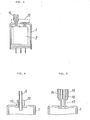
- FIGURE 1 is a sectioned side view of an embodiment of a container suitable for working manufacturing method of the present invention
- FIGS. 2(a), (b) and (c) are explanatory views of the manufacturing method of this invention
- FIG. 3 is a sectioned side view of FIG. 2(a)
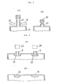
- FIGS. 4 and 5 are fragmentary sectioned reference views for explaining respectively different gas substitution methods for explaining this invention
- FIGS. 6(a) and (b) are fragmentary sectioned views for explaining an embodiment of the manufacturing method of this invention
- FIGS. 7(a) and (b) are sectioned side views of essential parts of the container in the embodiment of FIG. 1 for showing a state before the gas substitution and that after the tight sealing of the container.
- the container 1 is molded of such thermoplastic resin as a polyacrylate resin, polycarbonate resin, polyamide resin, polybutylene resin, terephthalate resin or the like so as to form in one direction of a box-like shape an opening 3 through which such an electric switch 2 as an electromagnetic relay or the like is put in and in the other different direction gas substituting ports 4 and 5 communicating the interior and exterior of the container with each other.through a fine hole of an inner diameter of about 0.8 mm.
- thermoplastic resin as a polyacrylate resin, polycarbonate resin, polyamide resin, polybutylene resin, terephthalate resin or the like
- the electric switch 2 is installed on an insulating base 6 consisting of a phenol resin, glass fiber reinforced nylon or the like and this insulating base 6 is brought into abutment with a step 3a in the opening 3 of the container 1 so as to close the opening 3. Electric connection of the switch to the exterior is made through terminals 7 projecting out of the container from the insulating base 6. A tight sealing of the opening 3 is achieved with a filler layer 8 consisting of an epoxy resin applied in a half-hardened state to the lower surface of the insulating base 6 and heated.
- FIGS. 2(a), (b) and (c) are showing, in order to explain the manufacturing method of the present invention, positional relations in respective steps between the container,1, a nozzle 9 for feeding a gas into this container land heating punches 10 for tightly sealing the gas substituting ports 4 and 5 of the container 1, as well as deforming states of the gas substituting ports 4 and 5.
- the nozzle 9 is of an inner diameter of about 1.2 mm. and is connected to a pressure tank not shown which storing such inert gas as nitrogen gas, argon gas or the like, such corrosive gas as sulfur, chlorine, or the-like, such organic gas as Nox (nitrogen oxide) or clean air containing no moisture.
- the heating punches 10 are heated by an electric or other means in advance to a temperature of about 240 to 260°C, at which the thermoplastic resin material forming the container 1 melts.
- the nozzle 9 is brought into close proximity to or butted against one, for example, 4 of the gas substituting ports, and a gas G is poured and charged into the container 1 by opening a valve of the pressure tank, so that the air staying in the container 1 will be discharged out substantially through the other gas substituting port 5 (see FIG. 3) due to that the concentration of gas G inside the container 1 is elevated as the gas pouring is continued and thereby the gas substitution will be performed.
- a gas charging of a concentration of about 95% is performed by pouring the gas of a volume about twice as large as the volume of the container.
- the container 1 is tightly sealed by closing the gas substituting ports 4 and 5. That is, as shown in FIG. 2(b), the tight sealing is performed in such that the nozzle 9 is separated upward from the gas substituting port 4 and the heating punches 10 are moved in the horizontal direction to hold, squeeze and melt the gas substituting port 4. If the height of tubular body of the gas substituting port 4 is made to be sufficient, the melting tight seal of the gas substituting ports 4 and 5 may be of course performed with the heating punches 10 while the nozzle 9 is brought into close proximity to or butted against the gas substituting port 4, that is, while feeding the gas into the container 1.
- FIG. 2(b) the tight sealing is performed in such that the nozzle 9 is separated upward from the gas substituting port 4 and the heating punches 10 are moved in the horizontal direction to hold, squeeze and melt the gas substituting port 4.
- the melting tight seal of the gas substituting ports 4 and 5 may be of course performed with the heating punches 10 while the nozzle 9 is brought into close proximity to or butted against the gas substituting port
- 2(c) is to explain a step to be added as required for improving the appearance of tightly sealed portions of the gas substituting ports after the above described step, in which drawing the shape of the gas substituting ports 4 and 5 is finished with a heating jig 11 provided separately from the above referred heating punches 10 and moved toward the gas substituting ports 4 and 5 from above.
- FIGS. 4 and 5 are reference views for explaining the features of the embodiment of FIG. 1 to 3 according to the present invention and, whereas the container 1 in the embodiment has two gas substituting ports, there are shown another aspects of the embodiment and having a single gas substituting port.
- the nozzle 9 is inserted through a gas substituting port 12 'of the container 1 so that its tip end will reach the interior of the container 1, the gas G fed from the pressure tank not shown is fed into the container 1 through the nozzle 9 and any gas to be discharged out of the container 1 is discharged through a clearance 13 between the inner wall of the gas substituting port 12 and the outer wall of the nozzle 9.
- a nozzle of a special structure wherein this nozzle 14 is provided with two independent paths 15 and 16, one of which path 15 is connected to a pressure tank not shown so as to contribute to the gas feeding and the other of which path 16 is opened to the atmosphere so as to contribute to the exhaustion of gas inside the container.
- the respective feeding and exhausting paths are required for one gas substituting port, there is the same problem as in the aspect of FIG. 4.
- FIGS. 6(a) and (b) are to explain an example of the gas substituting port sealing in the case where the material of the container 1 is a metal, wherein a gas substituting port 19 of a container 17 formed of a soft metal material is squeezed as in FIG. 6(b) by means of punches 18 movable in the horizontal direction (see FIG. 6(a)) and thereafter an opening 20 is filled with such molten metal 21 as a solder and tightly sealed.
- FIGS. 7(a) and (b) show the tight sealed state of the gas substituting ports in the case according to the embodiment of FIG. 1, in which embodiment the gas substituting ports 4 and 5 are retracted at their opening bases 21 and 22 to be inside the container and below the top end surface of the container 1. While in the case of such structure the melting tight seal is achieved as shown in FIG. 7(b) by means of heating jigs 23 and 24 moved toward the respective gas substituting ports from above as shown in FIG. 7(a), the opening bases 21 and 22 of the gas substituting ports 4 and 5 in this case are retracted inside the container so that melted and sealed portions 25 and 26 will be positioned below the top end surface of the container 1, whereby the top end surface of the container 1 can be kept flat.
- the container provided at least with two gas substituting ports is made hermetic except at the gas substituting ports by tightly sealing the opening for housing the electric switch after the switch is housed therein, then a gas is poured and charged into this container through the nozzle brought into close proximity to, butted against or inserted into one of the gas substituting ports while allowing any gas in the container to escape through the other gas substituting port and, when the concentration of the charged gas in the container has reached the predetermined level, the gas substituting ports are tightly sealed by the heating punches or the like with the container kept at its position or moved as required, whereby the gas charging is completed, so that the gas charging step can be made in the general atmosphere, thus, as compared with the conventional gas charging made within the pressure reducing chamber, improvements in respect of the loss of gas charged and gas substituting speed as well as the simplicity of the tight sealing of gas substituting ports are achieved, the exhaustion of air in the container by means of the pressure reducing chamber is not required
- FIG. 1 is a sectioned side view of an embodiment of the container suitable for working the present invention
- FIGS. 2(a), (b) and (c) are schematic view of essential parts for showing an example of the manufacturing method of the present invention
- FIG. 3 is a sectioned side view of FIG. 2(a)
- FIGS. 4 and 5 are reference views as fragmentarily sectioned for .explaining respectively different gas substitution methods for explaining this invention
- FIGS. 7(a) and (b) are sectioned side views of essential parts showing the states before the gas substitution and after the tight sealing of the container in the embodiment of FIG. 1.
- a container made of a thermoplastic resin and provided with two gas substituting ports is made hermetical except at the gas substituting ports by tightly sealing an opening after housing therein an electric switch, then a gas is poured and charged into this container through a nozzle butted against one of the gas substituting ports while a gas discharge is performed through the other gas substituting port and, when the concentration of the charged gas in the container has reached a required level, the gas substituting ports of the container are melted and tightly sealed with heating punches.
Abstract
Description
- Method of Manufacturing Gas-Charged Electric Switches
- This invention relates to a method of manufacturing gas-charged electric switches wherein an inert gas is poured, charged and sealed in a container for housing an electric switch to protect the switch from oxidation and deterioration due to an arc generation and, more particularly, to an improved method of manufacturing the gas-charged electric switches wherein steps of said pouring and charging of the gas and subsequent sealing of the container are simplified and these steps are made suitable for being performed in sequential steps in combination with other steps.
- It is general that the gas pouring and charging step in the method of manufacturing the gas-charged electric switches is performed by utilizing a pressure reducing chamber. Here, the pressure reducing chamber is the one which renders a gas substitution to be performable by discharging the interior gas by means of a reduction of pressure and thereafter supplying an inert gas (or clean air), that is, conventionally, gas pouring and charging step is generally performed by accommodating the container which houses therein the electric switch and is sealed except gas substituting ports in the pressure reducing chamber and carrying out indirectly the gas substitution by means of the pressure reduction of the pressure reducing chamber and of the inert gas supply thereto. Next, in the conventional method, the container subjected to the gas substitution is temporarily sealed at the gas substituting ports, taken out of the pressure reducing chamber into the general atmosphere and tightly sealed at the gas substituting ports by such measure as heat adhesion or the like.
- Therefore, according to such general method, the container has to be once carried into the pressure reducing chamber and to be again returned to the general atmosphere after performing the gas substitution so that certain difficulty is involved in incorporating the method in a part of an integrated continuous production line performed in the general atmosphere by means of a belt conveyer system, and further the method is rendered complicated since the sealing of gas substituting ports is made once temporarily in the pressure reducing chamber and thereafter finally in the general atmosphere. Since the gas substitution with respect to the container according to such general method is, further, indirectly performed as a result of the gas substitution made.with respect to the entire pressure reducing chamber, it takes a considerable time for elevating the concentration of gas in the respective containers to a predetermined level and, further, since the gas fed into the pressure reducing chamber but not poured into the respective containers is originally unnecessary, there arise a remarkable want of economy specifically when an expensive gas is used.
- A primary object of the present invention is, therefore, to provide a method of manufacturing gas-charged electric switches wherein the step of pouring and charging a gas into a container can be carried out in the general atmosphere so as to be economical.
- Another object of the present invention is to provide a method of manufacturing gas-charged electric switches wherein.the gas pouring and charging are quick and any loss of the gas is low.
- Another object of the present invention is to provide a container optimum for working such manufacturing method as above.
- According to the present invention, a gas substitution is performed in the general atmosphere and directly with respect to individual container containing an electric switch as tightly sealed except at gas substituting ports, whereby the above described objects are well achieved. Further according to the present invention, a gas is poured and charged into a container having a discharging path so as to gradually elevate the concentration of the gas in the container and to substantially discharge the gas out of the container, whereby the gas substitution is performed in a simple manner and features of the present invention achievable due to the gas substitution performed in the general atmosphere are further enhanced.
- The method of manufacturing gas-charged electric switches according to the present invention shall be further explained in the followings with reference to accompanying drawings of embodiments.
- FIGURE 1 is a sectioned side view of an embodiment of a container suitable for working manufacturing method of the present invention; FIGS. 2(a), (b) and (c) are explanatory views of the manufacturing method of this invention; FIG. 3 is a sectioned side view of FIG. 2(a); FIGS. 4 and 5 are fragmentary sectioned reference views for explaining respectively different gas substitution methods for explaining this invention; FIGS. 6(a) and (b) are fragmentary sectioned views for explaining an embodiment of the manufacturing method of this invention; and FIGS. 7(a) and (b) are sectioned side views of essential parts of the container in the embodiment of FIG. 1 for showing a state before the gas substitution and that after the tight sealing of the container.
- In FIG. 1 showing an embodiment of a container specifically suitable for working the manufacturing method of the present invention, the
container 1 is molded of such thermoplastic resin as a polyacrylate resin, polycarbonate resin, polyamide resin, polybutylene resin, terephthalate resin or the like so as to form in one direction of a box-like shape an opening 3 through which such anelectric switch 2 as an electromagnetic relay or the like is put in and in the other different direction gassubstituting ports electric switch 2 is installed on aninsulating base 6 consisting of a phenol resin, glass fiber reinforced nylon or the like and thisinsulating base 6 is brought into abutment with a step 3a in the opening 3 of thecontainer 1 so as to close the opening 3. Electric connection of the switch to the exterior is made throughterminals 7 projecting out of the container from theinsulating base 6. A tight sealing of the opening 3 is achieved with a filler layer 8 consisting of an epoxy resin applied in a half-hardened state to the lower surface of theinsulating base 6 and heated. - FIGS. 2(a), (b) and (c) are showing, in order to explain the manufacturing method of the present invention, positional relations in respective steps between the container,1, a nozzle 9 for feeding a gas into this container
land heating punches 10 for tightly sealing thegas substituting ports container 1, as well as deforming states of thegas substituting ports - Here, the nozzle 9 is of an inner diameter of about 1.2 mm. and is connected to a pressure tank not shown which storing such inert gas as nitrogen gas, argon gas or the like, such corrosive gas as sulfur, chlorine, or the-like, such organic gas as Nox (nitrogen oxide) or clean air containing no moisture. The
heating punches 10 are heated by an electric or other means in advance to a temperature of about 240 to 260°C, at which the thermoplastic resin material forming thecontainer 1 melts. - According to the manufacturing method of the present invention, as shown in FIG. 2(a), first, the nozzle 9 is brought into close proximity to or butted against one, for example, 4 of the gas substituting ports, and a gas G is poured and charged into the
container 1 by opening a valve of the pressure tank, so that the air staying in thecontainer 1 will be discharged out substantially through the other gas substituting port 5 (see FIG. 3) due to that the concentration of gas G inside thecontainer 1 is elevated as the gas pouring is continued and thereby the gas substitution will be performed. In this manner of gas substitution, a gas charging of a concentration of about 95% is performed by pouring the gas of a volume about twice as large as the volume of the container. When the concentration of the gas in thecontainer 1 thus reaches a predetermined level, next, thecontainer 1 is tightly sealed by closing thegas substituting ports gas substituting port 4 and theheating punches 10 are moved in the horizontal direction to hold, squeeze and melt thegas substituting port 4. If the height of tubular body of thegas substituting port 4 is made to be sufficient, the melting tight seal of thegas substituting ports heating punches 10 while the nozzle 9 is brought into close proximity to or butted against thegas substituting port 4, that is, while feeding the gas into thecontainer 1. FIG. 2(c) is to explain a step to be added as required for improving the appearance of tightly sealed portions of the gas substituting ports after the above described step, in which drawing the shape of thegas substituting ports heating punches 10 and moved toward thegas substituting ports - FIGS. 4 and 5 are reference views for explaining the features of the embodiment of FIG. 1 to 3 according to the present invention and, whereas the
container 1 in the embodiment has two gas substituting ports, there are shown another aspects of the embodiment and having a single gas substituting port. In the case of FIG. 4, the nozzle 9 is inserted through a gas substituting port 12 'of thecontainer 1 so that its tip end will reach the interior of thecontainer 1, the gas G fed from the pressure tank not shown is fed into thecontainer 1 through the nozzle 9 and any gas to be discharged out of thecontainer 1 is discharged through aclearance 13 between the inner wall of thegas substituting port 12 and the outer wall of the nozzle 9. While the manufacturing method of the present invention can be also worked in this aspect, there arise such difficulties that, if it is applied to a gas substituting port of a limited inner diameter, the inner diameter of the nozzle and theclearance 13 have to be made small and gas substituting speed is lowered, and that, if the inner diameter of the gas substituting port is made large enough for allowing the inner nozzle diameter andclearance 13 to be large on the contrary, the melting tight seal of the gas substituting port is hard to be perfectly achieved with respect to the container of a limited thickness. Therefore, it can be said that, though the present invention can be worked even by this embodiment, the before described embodiment is more advantageous in this respect. - Further, in the case of FIG.'5, a nozzle of a special structure is used, wherein this
nozzle 14 is provided with twoindependent paths path 15 is connected to a pressure tank not shown so as to contribute to the gas feeding and the other of whichpath 16 is opened to the atmosphere so as to contribute to the exhaustion of gas inside the container. Even in such aspect of the invention, the respective feeding and exhausting paths are required for one gas substituting port, there is the same problem as in the aspect of FIG. 4. - FIGS. 6(a) and (b) are to explain an example of the gas substituting port sealing in the case where the material of the
container 1 is a metal, wherein agas substituting port 19 of acontainer 17 formed of a soft metal material is squeezed as in FIG. 6(b) by means ofpunches 18 movable in the horizontal direction (see FIG. 6(a)) and thereafter anopening 20 is filled with suchmolten metal 21 as a solder and tightly sealed. - FIGS. 7(a) and (b) show the tight sealed state of the gas substituting ports in the case according to the embodiment of FIG. 1, in which embodiment the
gas substituting ports opening bases container 1. While in the case of such structure the melting tight seal is achieved as shown in FIG. 7(b) by means ofheating jigs opening bases gas substituting ports portions container 1, whereby the top end surface of thecontainer 1 can be kept flat. - As has been explained with reference to the respective foregoing embodiments, according to the present invention, the container provided at least with two gas substituting ports is made hermetic except at the gas substituting ports by tightly sealing the opening for housing the electric switch after the switch is housed therein, then a gas is poured and charged into this container through the nozzle brought into close proximity to, butted against or inserted into one of the gas substituting ports while allowing any gas in the container to escape through the other gas substituting port and, when the concentration of the charged gas in the container has reached the predetermined level, the gas substituting ports are tightly sealed by the heating punches or the like with the container kept at its position or moved as required, whereby the gas charging is completed, so that the gas charging step can be made in the general atmosphere, thus, as compared with the conventional gas charging made within the pressure reducing chamber, improvements in respect of the loss of gas charged and gas substituting speed as well as the simplicity of the tight sealing of gas substituting ports are achieved, the exhaustion of air in the container by means of the pressure reducing chamber is not required but the gas supply only is sufficient since another gas exhausting path than the gas feeding path is provided in pouring and charging the gas, a positive melting tight seal is made possible since the inner diameter of each port can be made as small as possible and a minimization of the gas charging steps and the reliability thereof, as well as a simplification of working means can be further promoted.
- FIG. 1 is a sectioned side view of an embodiment of the container suitable for working the present invention; FIGS. 2(a), (b) and (c) are schematic view of essential parts for showing an example of the manufacturing method of the present invention; FIG. 3 is a sectioned side view of FIG. 2(a); FIGS. 4 and 5 are reference views as fragmentarily sectioned for .explaining respectively different gas substitution methods for explaining this invention; and FIGS. 7(a) and (b) are sectioned side views of essential parts showing the states before the gas substitution and after the tight sealing of the container in the embodiment of FIG. 1.
- A container made of a thermoplastic resin and provided with two gas substituting ports is made hermetical except at the gas substituting ports by tightly sealing an opening after housing therein an electric switch, then a gas is poured and charged into this container through a nozzle butted against one of the gas substituting ports while a gas discharge is performed through the other gas substituting port and, when the concentration of the charged gas in the container has reached a required level, the gas substituting ports of the container are melted and tightly sealed with heating punches.
Claims (1)
- A method of manufacturing gas-charged electric switches characterized in that an electric switch housing step in which an electric switch is housed in a container provided with two gas substituting ports and with an electric switch housing opening and said opening is tightly sealed, a gas pouring step in which a gas is poured through one of said gas substituting ports and a gas in the container is discharged through the other gas substituting port, and a gas sealing step in which the gas substituting ports are tightly sealed with punches are performed sequentially in the general atmosphere.
Applications Claiming Priority (3)
| Application Number | Priority Date | Filing Date | Title |
|---|---|---|---|
| JP11251278A JPS5539154A (en) | 1978-09-12 | 1978-09-12 | Method of fabricating gassfilled electric switch |
| JP112512/78 | 1978-09-12 | ||
| PCT/JP1979/000045 WO1980000637A1 (en) | 1978-09-12 | 1979-02-26 | Method of manufacturing gas-filled electric switch |
Publications (3)
| Publication Number | Publication Date |
|---|---|
| EP0026231A4 EP0026231A4 (en) | 1981-01-22 |
| EP0026231A1 true EP0026231A1 (en) | 1981-04-08 |
| EP0026231B1 EP0026231B1 (en) | 1984-06-20 |
Family
ID=26420047
Family Applications (1)
| Application Number | Title | Priority Date | Filing Date |
|---|---|---|---|
| EP79900369A Expired EP0026231B1 (en) | 1978-09-12 | 1980-04-08 | Method of manufacturing gas-filled electric switch |
Country Status (6)
| Country | Link |
|---|---|
| US (1) | US4309816A (en) |
| EP (1) | EP0026231B1 (en) |
| JP (1) | JPS5539154A (en) |
| DE (2) | DE2953127C1 (en) |
| GB (1) | GB2059682B (en) |
| WO (1) | WO1980000637A1 (en) |
Cited By (5)
| Publication number | Priority date | Publication date | Assignee | Title |
|---|---|---|---|---|
| DE3308791A1 (en) * | 1983-03-12 | 1984-09-20 | Standard Elektrik Lorenz Ag, 7000 Stuttgart | METHOD FOR SEALING A RELAY |
| EP0198152A2 (en) * | 1985-04-12 | 1986-10-22 | Felten & Guilleaume Energietechnik AG | Relay and method of cleaning the relay |
| FR2590074A1 (en) * | 1985-08-30 | 1987-05-15 | Gen Electric | LOW VOLTAGE VACUUM CIRCUIT SWITCH |
| EP0434463A2 (en) * | 1989-12-22 | 1991-06-26 | Eev Limited | High voltage relay |
| EP0574058A2 (en) * | 1992-06-11 | 1993-12-15 | Alcatel STR AG | Relay |
Families Citing this family (11)
| Publication number | Priority date | Publication date | Assignee | Title |
|---|---|---|---|---|
| DE3319329C2 (en) * | 1983-05-27 | 1985-05-30 | Haller-Relais GmbH, 7209 Wehingen | Relay with wash-tight base plate |
| JPS6429726U (en) * | 1987-08-14 | 1989-02-22 | ||
| DE8809866U1 (en) * | 1988-08-02 | 1989-12-21 | Siemens Ag, 1000 Berlin Und 8000 Muenchen, De | |
| DE8905080U1 (en) * | 1989-04-21 | 1990-08-16 | Siemens Ag, 1000 Berlin Und 8000 Muenchen, De | |
| US5450109A (en) * | 1993-03-24 | 1995-09-12 | Hewlett-Packard Company | Barrier alignment and process monitor for TIJ printheads |
| US5359164A (en) * | 1993-05-14 | 1994-10-25 | Eaton Corporation | Illuminated switching assembly |
| DE69734440T2 (en) * | 1996-02-27 | 2006-05-24 | Kilovac Corp., Santa Barbara | IMPROVED SEALED RELAY |
| JP3543488B2 (en) * | 1996-05-28 | 2004-07-14 | 松下電工株式会社 | Manufacturing method and sealing method of sealed contact device |
| US8058576B2 (en) * | 2008-08-19 | 2011-11-15 | Tien-Ming Chou | Electronic switch mountable on a circuit board |
| JP6063193B2 (en) * | 2012-09-27 | 2017-01-18 | 日本特殊陶業株式会社 | Relay, relay manufacturing method |
| JP2022112549A (en) * | 2021-01-22 | 2022-08-03 | 富士電機機器制御株式会社 | Gas filling structure, sealed magnetic contactor, and gas filling method |
Family Cites Families (10)
| Publication number | Priority date | Publication date | Assignee | Title |
|---|---|---|---|---|
| US1971924A (en) * | 1930-02-20 | 1934-08-28 | Gen Electric Vapor Lamp Co | Mercury contact device |
| US2377265A (en) * | 1942-01-09 | 1945-05-29 | Gen Motors Corp | Sealed-in regulator |
| US2758261A (en) * | 1952-06-02 | 1956-08-07 | Rca Corp | Protection of semiconductor devices |
| US2951321A (en) * | 1957-03-08 | 1960-09-06 | Philips Corp | Method of sealing gas-tight enclosures |
| US3182382A (en) * | 1957-08-14 | 1965-05-11 | Clare & Co C P | Method of making sealed switches |
| FR1362586A (en) * | 1963-04-22 | 1964-06-05 | Cem Comp Electro Mec | Hermetic switch device |
| DE1496692A1 (en) * | 1965-07-12 | 1969-08-14 | Rafena Werke Veb | Melting process for gas-filled glass tubes |
| US3360382A (en) * | 1965-12-27 | 1967-12-26 | Scientific Atlanta | Method of packaging meat |
| US4004337A (en) * | 1973-02-20 | 1977-01-25 | Comtelco (U.K.) Limited | Apparatus for reed switch manufacture |
| US3897672A (en) * | 1974-09-11 | 1975-08-05 | Christian T Scheindel | Method of filling and pressurizing an aerosol can |
-
1978
- 1978-09-12 JP JP11251278A patent/JPS5539154A/en active Pending
-
1979
- 1979-02-26 GB GB8014715A patent/GB2059682B/en not_active Expired
- 1979-02-26 WO PCT/JP1979/000045 patent/WO1980000637A1/en unknown
- 1979-02-26 DE DE2953127A patent/DE2953127C1/en not_active Expired
- 1979-02-26 DE DE792953127T patent/DE2953127A1/en active Pending
-
1980
- 1980-04-08 EP EP79900369A patent/EP0026231B1/en not_active Expired
- 1980-05-12 US US06/197,802 patent/US4309816A/en not_active Expired - Lifetime
Non-Patent Citations (1)
| Title |
|---|
| See references of WO8000637A1 * |
Cited By (9)
| Publication number | Priority date | Publication date | Assignee | Title |
|---|---|---|---|---|
| DE3308791A1 (en) * | 1983-03-12 | 1984-09-20 | Standard Elektrik Lorenz Ag, 7000 Stuttgart | METHOD FOR SEALING A RELAY |
| EP0198152A2 (en) * | 1985-04-12 | 1986-10-22 | Felten & Guilleaume Energietechnik AG | Relay and method of cleaning the relay |
| EP0198152A3 (en) * | 1985-04-12 | 1989-04-05 | Felten & Guilleaume Energietechnik Ag | Extinguisher and method of cleaning the extinguisher |
| FR2590074A1 (en) * | 1985-08-30 | 1987-05-15 | Gen Electric | LOW VOLTAGE VACUUM CIRCUIT SWITCH |
| EP0434463A2 (en) * | 1989-12-22 | 1991-06-26 | Eev Limited | High voltage relay |
| EP0434463A3 (en) * | 1989-12-22 | 1992-07-01 | Eev Limited | Relay arrangements |
| EP0574058A2 (en) * | 1992-06-11 | 1993-12-15 | Alcatel STR AG | Relay |
| EP0574058A3 (en) * | 1992-06-11 | 1994-01-05 | Alcatel STR AG | Relay |
| US5554963A (en) * | 1992-06-11 | 1996-09-10 | Alcatel Str Ag | Gas-filled plastic enclosed relay |
Also Published As
| Publication number | Publication date |
|---|---|
| GB2059682B (en) | 1983-09-21 |
| DE2953127C1 (en) | 1983-12-22 |
| EP0026231B1 (en) | 1984-06-20 |
| JPS5539154A (en) | 1980-03-18 |
| DE2953127A1 (en) | 1981-01-29 |
| EP0026231A4 (en) | 1981-01-22 |
| WO1980000637A1 (en) | 1980-04-03 |
| GB2059682A (en) | 1981-04-23 |
| US4309816A (en) | 1982-01-12 |
Similar Documents
| Publication | Publication Date | Title |
|---|---|---|
| US4309816A (en) | Method of manufacturing gas-charged electric switches | |
| EP0559920B1 (en) | Vacuum casting apparatus | |
| EP2204864A2 (en) | Battery assembling method | |
| KR100250778B1 (en) | Metallic evacuated double-walled vessel and production method therefor | |
| KR100406840B1 (en) | Plasma display panel manufacturing apparatus and manufacturing method | |
| JPH04272413A (en) | Filling method for metallic sodium | |
| GB2100915A (en) | Handling molten radioactive waste | |
| US4612029A (en) | Method and apparatus for performing in-situ vacuum-assisted metal to glass sealing | |
| EP1016147B1 (en) | Sealed weldless battery circuit cast in cover | |
| US3977462A (en) | Apparatus for producing a die cast of a complicated shape | |
| KR100280013B1 (en) | Manufacturing method of insulation device made of synthetic resin | |
| JP2005285384A (en) | Sodium-sulfur battery and manufacturing method of the same | |
| KR20020024806A (en) | Sealed battery and method for manufacturing the same | |
| JP3936255B2 (en) | Sodium negative electrode for sodium sulfur battery and method for producing the same | |
| JP2570389B2 (en) | Method for manufacturing sodium-sulfur battery | |
| US20030080680A1 (en) | Method for making mercury capsule for use in fluorescent lamp | |
| US5928463A (en) | Device for producing heat insulating bodies | |
| EP1040977B1 (en) | Switch unit | |
| JP4218211B2 (en) | Manufacturing method of sealed contact device and manufacturing device thereof | |
| JPH02220327A (en) | Manufacture of double-ended high voltage discharge lamp | |
| US3951690A (en) | Base for leakproof electrochemical cells and method of forming the same | |
| EP0507330B1 (en) | A gas-filled discharge tube | |
| KR20170118391A (en) | Tantalum capacitor and method of fabricating the same | |
| SU1235389A1 (en) | Method of hermetic sealing of container with radioactive waste and container for radioactive waste | |
| JPS5549857A (en) | Enclosed alkaline battery |
Legal Events
| Date | Code | Title | Description |
|---|---|---|---|
| PUAI | Public reference made under article 153(3) epc to a published international application that has entered the european phase |
Free format text: ORIGINAL CODE: 0009012 |
|
| 17P | Request for examination filed |
Effective date: 19800507 |
|
| AK | Designated contracting states |
Designated state(s): FR |
|
| GRAA | (expected) grant |
Free format text: ORIGINAL CODE: 0009210 |
|
| AK | Designated contracting states |
Designated state(s): FR |
|
| ET | Fr: translation filed | ||
| PLBE | No opposition filed within time limit |
Free format text: ORIGINAL CODE: 0009261 |
|
| STAA | Information on the status of an ep patent application or granted ep patent |
Free format text: STATUS: NO OPPOSITION FILED WITHIN TIME LIMIT |
|
| 26N | No opposition filed | ||
| PGFP | Annual fee paid to national office [announced via postgrant information from national office to epo] |
Ref country code: FR Payment date: 19980210 Year of fee payment: 20 |
|
| REG | Reference to a national code |
Ref country code: FR Ref legal event code: D6 |