EP0027566A2 - Font selection and compression device for a printer subsystem - Google Patents
Font selection and compression device for a printer subsystem Download PDFInfo
- Publication number
- EP0027566A2 EP0027566A2 EP80105798A EP80105798A EP0027566A2 EP 0027566 A2 EP0027566 A2 EP 0027566A2 EP 80105798 A EP80105798 A EP 80105798A EP 80105798 A EP80105798 A EP 80105798A EP 0027566 A2 EP0027566 A2 EP 0027566A2
- Authority
- EP
- European Patent Office
- Prior art keywords
- font
- printer
- images
- data
- Prior art date
- Legal status (The legal status is an assumption and is not a legal conclusion. Google has not performed a legal analysis and makes no representation as to the accuracy of the status listed.)
- Granted
Links
Images


Classifications
-
- B—PERFORMING OPERATIONS; TRANSPORTING
- B41—PRINTING; LINING MACHINES; TYPEWRITERS; STAMPS
- B41J—TYPEWRITERS; SELECTIVE PRINTING MECHANISMS, i.e. MECHANISMS PRINTING OTHERWISE THAN FROM A FORME; CORRECTION OF TYPOGRAPHICAL ERRORS
- B41J3/00—Typewriters or selective printing or marking mechanisms characterised by the purpose for which they are constructed
- B41J3/54—Typewriters or selective printing or marking mechanisms characterised by the purpose for which they are constructed with two or more sets of type or printing elements
-
- G—PHYSICS
- G06—COMPUTING; CALCULATING OR COUNTING
- G06F—ELECTRIC DIGITAL DATA PROCESSING
- G06F40/00—Handling natural language data
- G06F40/10—Text processing
- G06F40/103—Formatting, i.e. changing of presentation of documents
- G06F40/109—Font handling; Temporal or kinetic typography
-
- G—PHYSICS
- G06—COMPUTING; CALCULATING OR COUNTING
- G06K—GRAPHICAL DATA READING; PRESENTATION OF DATA; RECORD CARRIERS; HANDLING RECORD CARRIERS
- G06K15/00—Arrangements for producing a permanent visual presentation of the output data, e.g. computer output printers
- G06K15/02—Arrangements for producing a permanent visual presentation of the output data, e.g. computer output printers using printers
- G06K15/10—Arrangements for producing a permanent visual presentation of the output data, e.g. computer output printers using printers by matrix printers
-
- G—PHYSICS
- G06—COMPUTING; CALCULATING OR COUNTING
- G06K—GRAPHICAL DATA READING; PRESENTATION OF DATA; RECORD CARRIERS; HANDLING RECORD CARRIERS
- G06K15/00—Arrangements for producing a permanent visual presentation of the output data, e.g. computer output printers
- G06K15/02—Arrangements for producing a permanent visual presentation of the output data, e.g. computer output printers using printers
- G06K15/18—Conditioning data for presenting it to the physical printing elements
- G06K15/1827—Accessing generic data, e.g. fonts
- G06K15/1828—Accessing generic data, e.g. fonts characterized by the kind of storage accessed
Definitions
- the invention relates to a font selection and compression device for a printer subsystem interconnected with a host system this device enabling storage and selection of a multiplicity of fonts in limited memory space.
- storage facilities are provided for a printer subsystem, the storage facilities 'being preloaded with a large number of font images arranged generally in accordance with individual languages accessible by the printer subsystem on a real time basis as printing operations proceed.
- this arrangement it is possible to print more than one language in individual lines of characters with a rapid switchover from one language to another in a manner that the switchover is hardly noticeable by the user.
- special symbols are accommodated. That is, the customer may require symbols that are unique to his particular printing operations and that are ordinarily not encountered by any other customer.
- the font storage is on a compressed basis, that is numerous font images are stored in a relatively limited amount of storage space by a compression technique.
- the printer subsystem is loaded with a "base" font image set that is the normal font image used by the particular printer subsystem.
- the "base” image can be replaced by other font images.
- the printer subsystem ordinarily returns to the base font image set.
- the fonts are stored in selected areas of a read only storage, the images being accessed during printer operations as required for generation of wire images in the printer unit. Pointer tables and data tables are used for the base font images, modifications for the base font images, and alternative font images that may be selected by the subsystem.
- printer subsystem typically capable of printing in a high range of lines per minute on continuous forms.
- the particular printer subsystem described herein is associated with a host system or processor, responds to command and data signals from the host to print on the forms and in turn provides status signals to the host during operations.
- the printer itself is an output line printer designed to satisfy a variety of printing requirements in data processing, data collection, data entry, and communications systems. It can be used as a system printer or a remote work station printer.
- Fig. 1 illustrates a representative system configuration including a host system 1 and the printer subsystem 2 which includes a printer control unit 3 and printer electronics 4.
- Command and data signals are provided by the host system by way of interface 5, and command and control signals are provided from printer control unit 3-to the printer electronics 4 by way of bus 6.
- Status signals are supplied by printer control unit 3 to host system I by way of interface 5.
- the host system 1 generates information including commands and data and monitors status.
- Printer control unit 3 receives the commands and data, decodes the commands, checks for errors and generates status information, controls printing and spacing, and contains printer diagnostics.
- Printer electronics 4 executes decoded control unit commands, monitors all printer operations, activates print wires, drives motors, senses printer emitters, and controls operator panel lights and switching circuitry. It controls the tractor/platen mechanism, the ribbon drive, the print head (i.e., actuator group) carrier, the operator panel, and the printer sensors.
- the elements of the system such as the printer control unit and printer electronics, incorporate one or more microprocessors or microcomputers to analyze commands and data and to control operations.
- Figs. 2 and 3 illustrate various components of the printer all of which are housed in the console 10.
- Various access panels or covers such as those designated 11, 12, and 13 are provided.
- Top cover 11 has a window 14 that enables an operator to observe forms movement during operation of the printer and when the cover is closed.
- Forms (documents) 15 are provided from a stack 16 and can be fed in one embodiment upwardly or downwardly as viewed in Figs. 2 and 3 by means of a forms feed assembly 20 which includes one or more sets of forms tractors such as the upper set comprising tractors 90 and 91.
- a forms guide 28 guides the forms after printing to a takeup stack, not shown but positioned below the printing mechanism and to the rear of the printer console.
- the printer incorporates a print assembly 30 that is positioned generally in a horizontal relationship with respect to forms 15 at a print station 32. Print assembly 30 is more clearly visible in other views. This is also true of the printer ribbon drive assembly 40 which is located in closer proximity to the front of the printer. Printer control unit 3 and its associated microprocessors are generally located behind the side cover 13.
- a ribbon 41 is provided on one of the spools 42 or 43, which are disposable.
- Each box of ribbons would preferably contain a disposable ribbon shield 46 that fits between print assembly 30 and forms 15 to keep ribbon 41 in proper alignment and to minimize hold ink smudging on forms 15.
- Two motors shown more clearly in Fig. 8 drive ribbon 41 back and forth between spools 42 and 43.
- the printer control unit detects ribbon jams and end of ribbon (EOR) conditions. A ribbon jam turns on an error indicator and stops printing. An EOR condition reverses the ribbon drive direction.
- the printer includes an operator panel 26 (shown in greater detail in Fig. 4) that consists of several operator control keys (pushbuttons 51-55 and 60), two indicator lights 56, 57, a power on/off switch 58, and an operator panel display 59.
- operator control keys pushbuttons 51-55 and 60
- two indicator lights 56, 57 a light on/off switch 58
- an operator panel display 59 an operator panel display 59.
- the operator can:start or stop printing and view the last line printed, set print density, position the forms up or down one page or one line at a tine, move the forms incrementally up or down for fine adjustment, and start or stop the diagnostic tests when selected by a mode switch, to be described.
- the indicator lights on the operator panel display notify the operator that:the printer is ready to print data from the using system (indicator light 57), the printer requires attention (indicator light 56), the current print density seating (panel display 59), errors, if any, have been detected, and the results of the diagnostic tests (panel display 59).
- a 16-position mode switch 65 is located behind the front door 12 and is shown in greater detail in Fig. 5.
- the on-line positions permits printing to be controlled by the using system. All other positions are off-line and do not allow printing to be initiated from the using system.
- the first two switch positions are used by the operator to select these modes:
- the remaining thirteen (13) positions of the mode switch designated "2-9" and "A-E" are used by service personnel to select a variety of diagnostic tests to aid in off-line problem determination and confirmation of service requirements.
- Fig. 6 illustrates a gate assembly 17 located behind side cover 13, Fig. 2, the gate assembly including modular printed circuit cards such as cards 8 that contain much of the circuit elements for printer control unit 3 and printer electronics 4, Fig. 1.
- Fig. 7 is a frontal view of a print emitter assembly 70 that includes an emitter glass 71 and an optical sensor assembly 72.
- Glass 71 is vertically positioned with respect to sensor assembly 72 and is mechanically attached to print mechanism 30 so that as the print heads, print actuators, and print wires move back and forth left to right and conversely as viewed in Fig. 7, glass 71 also moves in the same manner with respect to sensor assembly 72 to indicate horizontal position of the print wires.
- Cabling 73 supplies signals to the print actuators which are described in detail below.
- Figs. 8, 9 and 10 show the detail of construction of the forms feed assembly 20, the print assembly 30, the ribbon drive assembly 40, and various associated emitters. A general overview of these assemblies is first presented.
- forms feed assembly 20 has end paltes (side castings) 21 and 22 which support the various forms feed mechanisms including a drive motor 23 to drive tractors 90-93, the motor having a forms feed emitter assembly 24.
- the forms feed assembly has a separate end of forms and jam detector emitter 25.
- Assembly 20 also includes a platen 29 located behind the forms and against whi;h the print wires 33 are actuated during printing (See Fig. 9).
- the print assembly 30 includes a base casting 75 supporting various mechanisms including print motor 76, shown in phantom in Fig. 8 in order that other elements may be seen more easily, and connected to drive a print head carrier 31 with actuator block assembly 77 in a reciprocal fashion horizontally to effect printing on an inserted form.
- the print assembly also drives the print emitter assembly 70 having emitter glass 71 and optical sensor assembly 72.
- the ribbon drive assembly 40 includes a support casting 44, a cover 45, and drive motors 49 and 50.
- the forms feed assembly 20 pivots away from the base casting 75 at pivot points 80 and 81, the latter pivot point being best seen in Fig. 10, to allow access to thread the forms into position.
- Latches 83 and 84 are raised by the operator so that extremities 83a and 84a disengage eccentric pins 85 and 86 on the forms feed assembly.
- the forms feed tractor then pivots away from the operator as viewed in Figs. 3 and 8 and to the right as viewed in Fig. 10. This allows access to tractors 9093 so that the operator may load paper.
- the forms feed assembly is then reclosed and relatched by latches 83 and 84 for normal machine operation.
- the forms feed assembly includes means for adjusting for forms thickness. As mentioned, the entire forms feed assembly pivots back from the rest of the printer about pivot points 80 and 81. In the closed position the forms feed assembly is in such a position that a spiral cam 96 engages a pin 97 on the main carrier shaft 98 of the print assembly 30 (see also Fig. 9). Adjustment of the spiral cam and knob assembly 96 is such that it rotates the main carrier shaft 98. Assembly 96 is retained in position by a spring loaded detent assembly.
- eccentrics such as portion 98a on the left end of shaft 99 with tenon 100 onto which latch 83 is mounted. Rotation of shaft 98 thus moves latches 83 and 84 which changes the distance between assemblies 20 and 30 and thus the distance between the ends of print wires 33 and platen 29.
- This adjustment enables the printer to accomodate forms of various thicknesses.
- the printer can handle forms from one part to six parts thickness.
- the paper feeding is accomplished by the four sets of tractors 90-93 two above the print line and two below the print line.
- the individual tractors include drive chains to which pins are attached at the proper distance to engage the holes in the form.
- tractor 90 has drive chain 101 with pins 102.
- Chain 101 is driven by a sprocket 103 attached to a shaft 104 which also drives the sprocket and chains for tractor 91.
- Tractors 92 and 93 are driven from shaft 105. Because the tractors are above and below the print line, the printer is able to move the paper in either direction.
- the normal direction of forms drive is upwardly in Figs. 3 and 8. However, it is possible to move the paper downwardly, as well.
- Rotation of shafts 104 and 105 and forms feeding is accomplished by appropriate drive of motor 23 in the proper direction which in turn drives pulleys 106 and 107 (to which shafts 104 and 105 are connected) from motor pulley 108 by means of drive-timing belt 109.
- Cover 110 covers belt 109 and pulleys 106-108 during rotation.
- the forms feed emitter assembly 24 includes an emitter wheel 47 with marks to indicate rotation and a light emitting diode assembly 48 that serve to indicate extent of rotation of motor 23 in fi either direction and as a consequence, the extent of movement of the forms as they are driven by motor 23.
- the printer may be moved up one or two inches above where it normally resides so that it can be easily read and can be easily adjusted for registration.
- the paper is returned to its normal printing position back out of view of the operator.
- the printer may also be used in those applications where plotting is a requirement. In this case a plot may be generated by calculating one point at a time and moving the paper up and down much like a plotter rather than calculating the entire curve and printing it out from top to bottom in a raster mode.
- End of forms and jam detection is accomplished in this assembly by a sprocket 112 just above the lower left tractor.
- the teeth in this sprocket protrude through a slot 113a in the flip cover 113.
- This sprocket is not driven by any mechanism but simply is supported by a bearing.
- the sprocket engages the feed holes in the paper as it is pulled past by the tractor assemblies.
- On the other end of the shaft 114 from the sprocket is a small optical emitter disc 115.
- the marks in this disc are sensed by an LED phototransistor assembly 116 and supplied to the electronics of the subsystem. The electronics verifies that marks have passed the phototransistor at some preselected frequency when the paper is being fed. If the mark is not sensed during that time, the machine is shut down as either the end of forms has occurred or a paper jam has occurred.
- the castings 88 and 89 supporting the tractors 90-93 are adjustable left or right in a coarse adjustment in order to adjust for the paper size used in a particular application. After they are properly positioned they are locked in place on shaft 67 by locking screws such as locking screw 87.
- All tractors are driven by the two shafts 104 and 105 from motor 23 as previously described.
- the motor adjusts in the side casting 21 in slots 120 in order to provide the correct tension for belt 109.
- a threaded knob 66 which engages shaft 67 to which both tractor castings clamp. This shaft floats between side castings 21 and 22 laterally.
- the threads in knob 15 engage threads on the right end of shaft 67.
- the knob is held in a solid position by a fork 68. Therefore knob 66 stays stationary and the threads driving through the shaft force shaft 67 laterally left or right, depending upon the direction in which knob 66 is rotated.
- Shaft 67 is always biased in one direction to take out play by a spring 69 on the left end of shaft. As the paper leaves the top of the tractors, it is guided up and toward the back of the machine and down by the wire guide 28.
- an adjustment is performed. This adjustment is made by inserting a gauge or piece of paper in the tractor assembly which locates the bottom pins in the correct relationship to the top pins. This is done by loosening a clamp 121 on the end of shaft 104. Once this position is obtained, then clamp 121 is tightened and in effect phases the top set of tractors to the bottom set so that holes in the paper will engage both sets of tractors correctly. Forms may be moved through the tractor forms feed mechanism manually by rotating knob 122. This knob simply engages the top drive shaft 104 of the upper tractor set and through the timing belt 109 provides rotational action to the lower tractor set, as well.
- a carrier 31 comprising actuator block 77 and support 78 accommodate all the print heads with their wire actuators 35 and print wires 33. Also, see Figs. 13 and 14-26.
- Actuator block 77 is designed to hold from two up to eight or nine print head groups of eight actuators each.
- a printer with eight print head groups as shown in Figs. 8 and 13, has sixty-four print wire actuators and sixty-four associated print wires. Only two actuators 35 are shown positioned in place in Fig. 8. The other sixty- two actuators would be located in apertures 133 only a few of which are depicted.
- lubricating assemblies 134 containing oil wicks are positioned in proximity to the print wires.
- the print wire actuators fire the wires to print dots to form characters.
- Carrier 31 is shuttled back and forth by a lead screw 36 driven by motor 76.
- Lead screw 36 drives the carrier back and forth through nuts which are attached to the carrier.
- carrier 31 is located at the extreme left, as viewed in Figs. 3 and 8 (to the right as viewed in Fig. 13), this is called the "home position".
- a cam 37 attached to the carrier engages a pin 38, the pin being attached to the main carrier shaft 98.
- the printer control unit signals the carrier to move all the way to the left, in which case cam 37 engages pin 38 to rotate the main carrier shaft 98 approximately 15 degrees.
- cam 37 engages pin 38 to rotate the main carrier shaft 98 approximately 15 degrees.
- the eccentrically located tenons such as tenon 100, previously described. These tenons engage the latches 83 and 84 so that the distance between the print assembly and the forms feed assembly is controlled by the latches.
- the eccentrics associated with latches 83 and 84 separate the forms feed assembly from the print assembly.
- motor 76 The purpose of motor 76, of course, is to move the carrier 31 back and forth in order to put the print actuators 35 and print wires 33 in the proper positions to print dots and form characters. Since the motion is back and forth, it requires a lot of energy to get the mass of carrier 31 and actuators 35 stopped and turned around at the end of each print line.
- a brushless DC motor is used. The commutation to the windings in the motor is done external to the motor through signals sent out of the motor via a Hall effect device emitter 39. In other words, the emitter 39 within the motor sends a signal out telling the printer control unit that it is now time to change from one motor winding to the next.
- the motor draws about 20 amperes during turnaround time and, because of the high current it draws and because of the torque constant required from the motor, it is built with rare earth magnets of Samarium cobalt which' provide double the flux density of other types of magnets.
- Samarium cobalt is not just used because of the higher flux density but also because its demagnetization occurrence is much higher and, therefore, more current can be sent through the motor without demagnetizing the internal magnets.
- carrier 31 that holds the print actuators 35 goes at a velocity of approximately 63,5cm per second.
- the turnaround cycle at the end of the print line requires 28 milliseconds approximately, resulting in a Gravity or "G" load in the neighborhood of 4 G's.
- the current necessary to fire the print actuators is carried to the actuators via the cable assemblies 73, Figs. 7 and 13, one for each group of eight actuators.
- the cabling, such as cable 73a, Fig. 8 is set in the machine in a semicircular loop so that as carrier 31 reciprocates it allows the cable to roll about a radius and therefore not put excessive stress on the cable wires.
- This loop in the cable is formed and held in shape by a steel backing strap 74. In this case there is one cable assembly for each group of eight actuators or a maximum of eight cable backing strap groups.
- the ribbon drive assembly 40 for the printer is shown in Fig. 8, but reference is also made to Figs. 3, 9, and 13.
- Spools 42 and 43 are shown with spool flanges but may be structured without spool flanges and contain the ribbon.
- the spools can be seen on either side of the machine near the front, Fig. 3.
- Drive for spool 43 is from motor 50, pinion gear 132 to a matching gear 119a formed on the underneath side of gear flange 119 then to spool 43.
- the ribbon path is from the left-hand spool 42 past posts 125 and 126, Figs.
- a ribbon shield 46 to be described in conjunction with Figs. 11-13 is generally located between posts 126 and.127 and is mounted on the two attachment spring members 130 and 131.
- Fig. 11 illustrates ribbon shield 46 that is particularly useful in the printer described herein.
- Fig. 12 is a cross-sectional view along the lines 12-12 in Fig. ll.
- Shield 46 has an elongated aperture 46a extending almost its entire length. The aperture enables the print wires 33 to press against the ribbon in the printer through the shield in order to print on forms 15.
- Shield 46 has slits 46b and 46c at opposite extremities to permit easy mounting in the printer on spring members 130 and 131 of the ribbon drive assembly, Fig. 13.
- Fig. 13 is an assembly view of the printer including forms feed assembly 20, printer assembly 30, and ribbon drive assembly 40.
- Ribbon drive assembly 40 includes the two ribbon spools 42 and 43 which alternatively serve as supply and takeup spools. If spool 42 is serving as the supply spool, ribbon 41 will be supplied past posts 125 and 126, through the ribbon shield 46 past posts 127 and 128 and thence to the takeup spool 43. Shield 46, Figs. 11 and 13, and ribbon 41, Fig. 13, are illustrated slightly on the bias relative to horizontal which is their more normal relationship in the printer. The ribbon drive assembly 40 is also positioned on a slight bias relative to horizontal to accommodate the bias of shield 46 and ribbon 41. In this condition aperture 46a assumes a horizontal relationship with respect to the print wires 33 and forms 15.
- the rightmost end of shield 46 is somewhat elevated in relation to the leftmost end in order that aperture 46a is maintained in a relatively horizontal position with respect to the print actuators in print mechanism 30.
- a few of the groups of print wires 33 are indicated at a breakaway section of shield 46.
- the print wires are reciprocated back and forth laterally in relation to a form, not shown in Fig. 13, in order to effect the printing of characters. The reciprocation is by means of drive mechanisms activated from motor 76.
- the activating signals for the actuators in print mechanisms 21 are supplied through cabling indicated at 73.
- FIG. 14-23 Enlarged views of the actuator block 77, guide 79, print wire actuators 35, lubricating assemblies 134, and various related mechanisms are shown in Figs. 14-23. Referring to Fig. 14, this better illustrates the arrangement of apertures 133 in actuator block 77 which can accommodate eight print heads with eight print wire actuators. Apertures 133a are used to mount actuators 35 while apertures 133b allow passage of barrels 136 of actuators 35 through actuator block 77 and guide 79 up to the print line.
- a typical lubricating assembly 134 comprises a cover 140, felt element 141, wick assembly 142, and housing 143 that contains lubricating oil.
- F ig. 15 illustrates a portion of face 79a of guide 79 while F ig. 16 illustrates a portion of face 79b of guide 79.
- Barrels 136 of actuators 35 pass through apertures 145 on face 79a of guide 79 and are retained by bolts such as bolt 146 passing through apertures 147 from the opposite side of guide 79.
- Individual actuator barrels 136 and print wires 33 project through apertures 148, Figs. 13 and 16.
- Figs. 17-22 illustrate several arrangements which permit mounting of a greater multiplicity of actuators in a given amount of space through actuator block 77 and guide 79.
- Figs. 17-19 illustrate one possible mounting arrangement for the actuators while Figs. 20-22 illustrate the actual mounting arrangement previously described in conjunction with Figs. 8, 13, and 14-16.
- Figs. 17-19 which represent an alternative mounting arrangement, print actuators 35a and print wires 35 for one print head set of eight (1-8) are arranged on a straight slope 150.
- This slope combined with actuator block 77a having a double angle configuration at 151, Fig. 18, results in a staggered print wire face-to-platen condition, Fig. 19.
- This print wire face-to-platen distance, shown as 8X, is critical to both the stroke and flight time of the print wires.
- Figs. 20-22 has a number of attributes, including improved functioning, increased coil clearance, and ease of manufacture.
- print wires 35 arranged in a set 1-8 are mounted in two offset sloped subsets 152a and 152b forming a sloped serrated pattern.
- Subset 151a includes print wires 1-4 of the set while subset 152b includes print wires 5-8.
- This combined with a straight surface 153 on actuator block 77 and angled actuators 35, Fig. 21, represent an in-line print wire face-to-platen condition as in Fig. 22.
- the print wire face-to-platen condition as in Fig. 22.
- the print wire face-to-platen distance, shown as X is at a minimum. This permits a higher printing rate and prevents wire breakage.
- the offset sloped print wire sets gives a greater clearance between wire positions which allows a larger actuator coil to be used.
- brackets 155 are still cut at an angle such as shown in Fig. 24.
- the angular relationships of the print actuators 35a with respect to the platen faces in Fig. 18 and print actuators 35 with respect to the platen face in Fig. 21 are somewhat larger than would be encountered in an actual implementation but they are shown this way to make the relationships easier to see.
- an actual angular relationship might be smaller such as the 4 ° 30' angle front face 155a on bracket 155 of actuator 35 in Fig. 24.
- Figs. 23-26 illustrate a preferred form of actuator 35.
- a print wire is provided having an armature which is retained in home position by a permanent magnet.
- an electromagnet is energized which overcomes the magnetic forces of the permanent magnet and propels the print wire toward the paper.
- F ig. 23 illustrates one side elevation of the actuator
- Fig. 24 illustrates the opposite side elevation.
- the actuator comprises a number of elements arranged in a generally concentric manner on bracket 155. It is noted that Fig. 24 is somewhat enlarged relative to Fig. 23. Reference is also made to Figs. 25 and 26 for details of the individual components of the actuator. Also, it is noted that some slight structural differences appear between the actuator shown in Figs. 23-26 and those illustrated in Figs. 17-22, the actuators in Figs. 17-22 being more diagrammatically illustrated.
- the actuator includes a barrel 136 for supporting print wire 33 in proper relationship for printing when mounted in actuator block 77 and guide 79. Attached to the leftmost end of print wire 33 as viewed in Fig.
- armature 156 which is arranged against a stop portion 156a of an adjustment screw 157 by forces exerted from a permanent magnet 158.
- electromagnet 160 is rapidly impulsed from an external source by way of connectors 161. Energization of coil 160 overcomes the magnetic flux forces of permanent magnet 158 moving armature 156 and print wire 33 to the right as viewed in Fig. 25 thus causing the rightmost end of print wire 33 which is in proximity to the forms, to print a dot on the forms.
- a bobbin housing 162 is made of metallic substances to provide a shielding effect with respect to electromagnet 160. It is found that this has been beneficial when numerous print wire actuators are mounted in position on actuator block 77 and guide 79 since it prevents stray impulses from reacting from one actuator to another nearly actuator. This has proven to be extremely advantageous when multiple print actuators are provided as in the present printer.
- a core element 163 provides a forward stop location for armature 156 in readiness for restoration by permanent magnet 158 against stop 157a as soon as current is removed from coil 162.
- Figure 26 is an end elevation of housing 162 along the lines 26-26 in Figure 25.
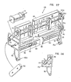
- Figs. 27 and 28 illustrate an alternative single direction forms feed assembly 170 which feeds forms only in the upward direction as viewed in these figures.
- this forms feed assembly has only a single upper set of tractors 171 and 172.
- a driving motor 173 provides driving force through gears 175 and 176 by way of timing belt 178.
- the various elements comprising the forms feed assembly are supported in a left end plate 180 and a right end plate 181.
- Fig. 28 is a left end elevation of the forms feed assembly 170 illustrating the positional relationships of motor 173, timing belt 178 and other elements.
- a cover plate 182 covers timing belt 178 during operations.
- Driving of the pin feeds on the two tractors 171 and 172 is analogous to the driving of the pin feeds for forms feed assembly 20 illustrated in Fig. 8 and previously described.
- the tractor drive includes a drive shaft 183.
- Lateral support for the forms feed assembly 170 is provided by an upper support 185 and a lower support 186.
- the assembly also includes a platen member 29a.
- Other elements such as knobs 1 and 22a, 66a, and 96a are analogous to their counterpart elements 122, 66, and 96 shown in Fig. 3.
- the tractor mounts to the printer base casting 75 in Fig. 8 at pivot points 80a and 81a.
- this forms feed assembly includes a pressure drag assembly 188 with compliant fingers 189. These fingers exert physical pressure against the paper when.in position against platen 29a and in the immediate vicinity of the printing station.
- the drag assembly 188 is also opened, but while the forms feed assembly moves toward the rear of the printer, the drag assembly moves toward the front.
- Spring element 187 enables drag assembly 188 to adjust to allow the forms to slide through when loading the forms.
- One additional cam element 190 cooperates with a follower 191 to provide adjustment of the pressure exerted by the drag assembly 188 on the paper for the purpose of accommodating various thicknesses of forms.
- the assembly includes an End of Forms sprocket assembly 192 that could also serve to detect paper jams and that works in an analogous fashion to assembly 25 with sprocket 112 shown in Fig. 8.
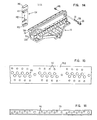
- Characters that are printed are formed by printing dots on the paper. These dots are printed by wires that are mounted in groups of eight on a carrier bar that moves back and forth adjacent to the print line. Printing is bidirectional with complete lines of print formed right-to-left and left- to-right. See Figs. 29, 30, 33A and 33B.
- a character is formed in a space that is eight dots high by nine dots wide. As shown in Fig. 30, two of the nine horizontal dot columns (1 and 9) are for spacing between characters. Any one wire can print a dot in four of the seven remaining horizontal dot positions (2 through 8). The printer can print 10 characters per inch or 15 characters per inch.
- top seven wires in the group to print a character in a format (or matrix) that is seven dots high and seven dots wide.
- the eighth (bottom) wire is used for certain lower case characters, special characters, and underlining.
- the number of print wire groups varies according to the printer model, and typically can be 2, 4, 6 or 8 groups. Printing speed increases with each additional wire group.
- Fig. 31 is a representation of the emitter glass 71 also shown in Figs. 7 and 8 and associated with the print mechanism 21. It has sections called “Ramp”, “Home”, and “Left Margin”. These are coded sections, designated Track A, Track B, and Track C. Track B is sometimes referred to as the "Turnaround" track. "Home” is indicated by all three tracks being clear. “Ramp” is when Track A and Track C are clear, but Track B is opaque. “Left Margin” is when only Track C is clear, and Tracks A and B are opaque. Left Margin can be told from Right Margin because Track B is clear on Right Margin whereas Track B is opaque on Left Margin.
- glass 71 is shown in a more normal representation with the left margin areas to the left and the right margin areas to the right.
- the emitter glass 71 is physically located in the machine with the right-hand part in Fig. 31 toward the left and the left-hand part in Fig. 31 toward the right as viewed in Figs. 7 and 8. This is due to the fact that the associated optical sensor 72 is physically located at the rightmost area of the strip when the print mechanism is in home position, and glass 71 actually is moved past the optical sensor assembly 72 from left to right as the print mechanism moves from left to right away from home position.
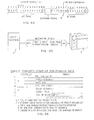
- Fig. 3.2 illustrates the development of emitter pulses from the emitter strip 35 shown in Fig. 31, the signals being termed “real emitters” when actually sensed from Track A.
- Option emitters (sometimes referred to as “false” emitters) are developed electronically in the printer control unit. The use of emitter 70 in keeping track of printing location is described. The emitter tells the electronics when the wires are in a proper position to be fired to print the dots in correct locations. It essentially divides the print line into columnar segments, each one of which is available to the electronics to lay down a print dot.
- Track A the basic track which controls the printing of dots has spacings of 0,56 mm. This corresponds to two print columns distance on the emitter in a normal print cycle and for ten characters per inch one option is inserted halfway in between.
- Each emitter track actuates one pair of light emitting diode-photo transistor (LED-PTX) sensors within sensor assembly 72.
- Track A provides print initiation pulses
- Track B provides turnaround information
- Track C indicates if the print heads are in either left or right margin.
- a signal for turnaround (reversal of print motor 76 direction) is given as soon as the last character has been printed.
- the motor now decelerates until it comes to a stop, and then immediately accelerates in the reverse direction until nominal speed is reached.
- the number of emitters of Track A are counted.
- the A sensor keeps increasing the count regardless of whether the print assembly moves to the right or left.
- provision is made electronically to convert this count so that the count increases when the print assembly moves in one direction and the count decreases when moving in the opposite direction.
- Track B has been added. It is assumed that the print assembly is moving to the right. After the last character has been printed and the signal for turnaround has been given, the print assembly will continue to move to the right and the count will increase. However, as soon as the next transition has been reached on Track B, the count is frozen. The print head now comes to a stop and reverses. When it again passes the transition where the count was frozen, the emitter counts will now be subtracted and a true position indication is maintained by the counter for Track A.
- the length of the Track B segments are chosen to be longer than the distance it takes the print head to come to a stop. The higner the print head speed and the longer the turnaround time, the longer must be the Track B segments. Thus, if the line is shorter than 132 characters at ten characters per inch, the carrier need not travel all the way to the right end of the print line. It may turn around soon after the printing is completed.
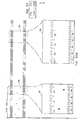
- Figs. 33A and 33B when arranged as shown in Fig. 34, comprise a diagram showing the physical relationship of the print heads when in the home position relative to character locations on a form to be printed. In addition, the emitter relationships are shown.
- print head 1 comprising eight print wires, is normally to the left of the nominal left margin when in home position.
- Print head 2 lies to the right of the left margin when the print assembly is in home position and the other print heads up to eight, as an example, are physically located at successively further positions to the right in relation to the form.
- the print wires are arranged in a sloped serrated pattern and are displaced two character positions apart horizontally, as shown in Fig. 37, and one dot location apart vertically. In order to print the character "H" as shown inset 195, it is necessary that all of the print wires in print head 1 sweep past the "H" dharact- er location to effect printing of the individual dots.
- each print head is required to pass at least far enough so that all of the wires in that print head will be able to print both the first vertical column of dots in the first character required as well as the last column of dots in the last character to be printed in the group of character locations assigned to that print head.
- print head 1 during printing movement of carrier 31, prints all of the characters that normally would appear underneath print head 2 when the print heads are in their home position.
- the printing of dots associated with print head 2 takes place under the home position for print head 3 and so on.
- Inset 196 illustrates the relationship of real and optional emitters, scmetimes referred to as "false" emitters, for both ten characters per inch and fifteen characters per inch.
- real emitters are found as indicated. These are physical real emitters derived from the emitter glass 71 as the print assembly sweeps from left to right or right to left during printing. The same real emitters are used for printing at fifteen characters per inch. However, when printing is at ten characters per inch, one additional (optional) emitter is necessary between each successive pair of real emitters to form the individual characters while, if characters are printed at fifteen characters per inch, two additional (optional) emitters are required between each successive pair of real emitters to handle the printing of dots for those characters.
- Inset 197 Fig. 33A, illustrates the character locations associated with the rightmost print wire of print head 2 and the leftmost print wire of print head 3. Print heads 4-7 are not shown since the relations essentially repeat those shown with respect to print heads 1-3.
- the rightmost wires of print head 8 are shown in Inset 198, Fig. 33B.
- Inset 199 shows that for ten characters per inch, 132 characters can be accommodated in a full print line while for fifteen characters per inch, 198 characters are accommodated.
- Fig. 35 is a highly diagrammatic block diagram of the general relationship of various system and control unit components including the two microprocessors 200 and 210 (also designated MPA and MPB), the Head Image Generator 220 and the random access memory 217 and indicates how the information is transferred that is generated by the Head Image Generator to print dots on the paper by actuation of the actuators.
- the two microprocessors 200 and 210 also designated MPA and MPB
- the Head Image Generator 220 also designated MPA and MPB
- the random access memory 217 indicates how the information is transferred that is generated by the Head Image Generator to print dots on the paper by actuation of the actuators.
- Microprocessor 200 handles communications;microprocessor 210 handles the control of the subsystems.
- Microprocessor 200 sets up in memory 217 the count and the text buffer that is to be printed at a selected addressable location. The information is then passed over to microprocessor 210 or the buffer that is to be used. The count is passed to the Head Image Generator 220 and also the address in memory 217 which is the text buffer to be printed.
- Head Image Generator (HIG) .220 knowing the buffer to be printed, accesses memory 217 and defines the dots for the characters to be printed at each of the successive columns assigned to each print head as print carrier 31 moves during printing. HIG passes the data to the Control microprocessor 210 giving it all the dots to be printed at that particular time. This is represented in Fig.
- Fig. 37 which includes a portion of head 1 and all of head 2.
- Fig. 37 illustrates printing at ten characters per inch.
- a string of "H's” is assumed to require printing.
- the darkened dots of the "H's” represent the wires above them that will actually print that dot.
- wire 4 prints the fourth dot down in the first column of the leftmost "H”. This is the second slice of firing for that particular character with another three wire fires being required for wire 4 to complete the horizontal bar portion of the "H”.
- the other seven wires in print head 1 fire at appropriate times to complete their assigned horizontal rows in that character.
- wire I is over an "H”; there is no wire over the next "H”; and wire 5 is over the third "H". If printing was at fifteen characters per inch, there would be no wires over two characters between wires I and 5 of head 2, rather than just one character as illustrated.
- the wire layout of "1 5 2 6 3 7 4 8" in Fig. 37 relates to the layout in Fig. 36 where it is shown how an "H" is laid out in relation to the actual wire slices.
- the printer subsystems may be connected by an interface cable to a controlling device (controller).
- the printer can be connected to the controlling device itself, or to another printer (or work station unit) with additional cabling.
- the controlling device to which the printer subsystem is attached may be a host computer system, Fig. 38, or a controller at a remote work station, Fig. 39. In either case, all information transfers (exchanges) between the controlling device and the printer control unit are started from the controlling device by a command. Information transfers ordinarily are not initiated by the printer.
- the printer subsystem may be directly connected to a host computer system, as in Fig. 38.
- all commands are supplied by the computer, along with the data to be printed.
- Responses from the printer are sent directly to the computer from the printer control unit.
- the printer subsystem may be connected to a work station controller, which in turn is remotely connected to a host computer system by a communications network - such as Systems Network Architecture/ Synchronous Data Link Control (SNA/SDLC).
- a communications network such as Systems Network Architecture/ Synchronous Data Link Control (SNA/SDLC).
- SNA/SDLC Systems Network Architecture/ Synchronous Data Link Control
- information (data) to be printed and printer formatting commands are transferred from the computer system to the work station controller.
- the work station controller then generates the operational commands and transfers all this information to the printer. Responses from the printer are sent to the work station controller then to the computer system by the communications network.
- SNA/SDLC Systems Network Architecture/ Synchronous Data Link Control
- the Cable Through Connector feature Fig. 40, connects multiple printers or other work station units on the same interface cable line to the system or controller.
- Units with this feature have address-setting switches and an additional cable connector.
- the customer assigns a unique address to each unit on the cable connector line and sets the address switches at installation time.
- the feature is not needed on the last unit on the line.
- the number of units that can be connected to the same line depends on the capability of the controlling device.
- the maximum cable length restriction is from the controlling device to the last unit on the line.
- the optional alarm produces a tone that alerts the operator to conditions that require operator attention.
- the interface cable may be either coaxial or twinaxial. Representative maximum cable lengths from the controller to the last device on the interface are:
- the type of cable selected depends on the requirements of the controlling device to which the printer subsystem is attached.
- the bit and frame synchronization (sync) patterns establish timing control between the controlling device and the printer.
- the data frame is the unit of information used to transfer all commands, data to be printed, and status information.
- the data stream can flow in either direction on the interface cable - but only in one direction at a time (half- duplex).
- the controlling device always initiates the data stream flow for either direction. Only one device on the interface can be communicating with the controlling device at a time.
- the data stream flows on the interface for each transfer of single or multiple frames of information.
- the cable carries no signal between information transfers.
- the information stream may be a mixture of operational commands, formatting commands, and data to be printed. Blocks of up to 256 frames may be included in the information stream for a given transfer.
- the information stream for any information transfer always begins with the bit-sync and frame-sync patterns, and ends with an end-of-message code in the last frame of the sequence.
- the end-of-message code causes turnaround on the cable, allowing-status information to be transferred in the opposite direction on the cable on the next sequence.
- the basic unit of information transfer is a 16-bit information frame.
- the information frame is used for transferring all commands, data, and status information between the controlling device and the printer.
- a Receive mode from controller to printer is illustrated in Fig. 42 and a Transmit mode from printer to controller is illustrated in Fig. 43.
- bits 0 through 2 are for timing control.
- Bit 3 the parity bit, is set to maintain an even bit count (even parity) in each frame.
- Bits 4, 5, and 6 are the address bits for selecting a specific printer (or other work station unit) attached to the interface. Up to seven units can be addressed by combinations of these bits (000 through 110 are valid addresses). A bit combination of 111 indicates an end-of-message and causes line turnaround.
- Bits 7 through 14 are for commands, data or status information. Bit 15, always on, is a synchronization bit.
- Printer addresses are coded in bits 4, 5, and 6 of the information frame, Fig. 44.
- the address for a single printer on the interface cable is 000.
- addresses can range from 000 through 110.
- Addresses of printers attached with the Cable Connector feature are set with switches by the customer.
- a bit combination of 111 is used as an end-of-message indicator in _ the last frame of a transfer sequence and, therefore, cannot be used as a valid address.
- the first frame following any signal turnaround on the cable is a command frame containing a valid printer address (000 through 110) for selecting a specific printer on the interface cable.
- a valid printer address 000 through 110
- Each successive frame following a command frame is then checked for the end-of-message code (111).
- All response frames from the printer to the controlling ,device, except the end-of-message frame, contain the address of the selected printer.
- printer response frames are requested by the controller to determine the readiness (or "status") of a printer for accepting data from the controller.
- status or "status”
- printer operational and error conditions are reported to the controller by means of printer response frames. These conditions are described in detail in the section below entitled "Status and error Information”.
- the printer control unit 3 (See Figs. 1 and 35, as examples) connects the printer to the interface cable from the controlling device, controls the flow of information to and from the controlling device and controls all internal printer functions.
- the printer control unit When data is received for printing, the printer control unit formats the data into print lines, using formatting commands (control codes) embedded in the data stream. Two print-line format buffers are used so one line can be printed while the next line is being formatted. This comprises a "lookahead" function which allows bidirectional printing for maximum throughput.
- EBCDIC Extended Binary Coded Decimal Interchange Code
- Operational commands determine the printer function to be performed, such as Write Data, Read Status, etc. (also, see Figs. 45 and 47A).
- Fig. 47A illustrates a representative operational command:"Poll.”
- Some operational commands require an additional command or data frame. In these cases, the next frame transmitted must contain that command or data frame.
- Operational commands are embedded in the data stream wherever required for proper control of the printer.
- FIG. 46 illustrates a representative sequence of events between a controlling unit and the printer subsystem to effect printing of data.
- SCS standard character string
- the printer subsystem responds to controller polling with a single status frame, Fig. 48.
- the printer continues to respond to controller polling with a single status frame until the printer receives a Set Mode command.
- the printer After receiving a Set Mode command, the printer responds to polling with two status frames, the second of which is shown in Fig. 49.
- This bit is used to maintain an even bit count (even parity).
- bits are used for selecting a specific printer attached to the interface. Up to seven printers can be addressed by the combinations (000 through 110). A bit combination of 111 indicates an end-of-message and causes line turnaround.
- Bits 11, 12, and 13 indicate a variety of exception status conditions. Until the exception status is reset, only Poll, Set Mode, and Reset commands are processed. The Write Control Data Command (if the exception status is not power-on transition) is also processed. The power-on transition exception status is reset by the Set Mode command. The exception status conditions are reset by the Write Control command (see "Write Control Data").
- bit 14 When bit 14 goes from 0 to 1 or 1 to 0, the using system determines that the response frame is current status. When bit 14 is unchanged from the previous response, the using system determines that the response frame is previous status. Any change in the response frame changes bit 14 from its previous state. Bit 14 is set to 0 after power-on.
- a synchronization bit that is always set to Frame 2 contains information shown in Fig. 49.
- the print complete bit is set to 0 when the printer detects an Active Write command.
- the print complete bit is set to 1 by Power-on reset, a Clear command, a Reset command, or when all input data is printed.
- the Cancel request bit is set to 1 when the operator presses the Cancel key on the Operator Panel. This bit is reset by the next Poll command (with Acknowledge bit set to 1), a Reset or Power-On reset.
- This bit is set to 1 indicates that an undefined character has been detected in the data stream. This bit is reset by the next Poll command (with Acknowledge bit set to 1), a Reset or Power-On reset.
- One response frame is sent for every Read Status command.
- the response frame sent only after the Activate Read command is received, contains a hex code that defines the status condition within the printer.
- the hex code corresponds to the last two digits of the error code that may be available as a system error message (depending on the using system). The first digits of these hex codes are also automatically displayed on the printer operator panel 26 when the error occurs.
- the defined conditions are:
- Fig. 50 illustrates various printer blocks of interest.
- a power supply 245 supplies the unit with all the power to drive and to control.
- the on/off switch 240 controls power supply 245 being on and off. From the power supply the cover interlock switch 242 enables and disables the 48- volt drive which controls much of the printer logic 243.
- Logic -243 once enabled, looks at operator panel 26 for information as to the operations to be performed.
- Mode switch 65 tells the logic which type of operation in testing procedures should be run.
- Print assembly 30 is controlled by the printer logic along with the forms assembly 20.
- Emitter devices 24 and 70 supply positional information to the printer logic.
- the printer logic also controls and talks with the interface panel 247 and passes information on the other parts of the printer.
- printer logic 243 which accepts inputs from the ribbon assembly to determine when the end of ribbon has occurred.
- Head servo 252 is a control block that insures that the print head is in the proper position at the proper time for the actuators to fire.
- Forms servo 253 is a control block that moves the forms to desired locations.
- Fans 254-258 are used to control temperature within the machine.
- printer logic 243 includes two microprocessor adapter blocks 200 and 210. The first one included is the Communications adapter CMA which accepts input and passes it to the second one which is the Control adapter CTA that actually controls the printer. These will be discussed in connection with Figs. 51A and 51B.
- Figs. 51A and 51B join together as shown in Fig. 52 to illustrate the details of the Printer Control Unit 3 and Electronics 4,
- the Printer Control Unit representing seven printed circuit cards.
- the first block is the Communications Interface 201 between the host system and digital printer electronics. That interface communicates with the Communications Adapter (CMA) 202 which is a microprocessor card that takes the host information and compiles it into a form that can be used by the rest of the printer.
- the CMA includes Communications microprocessor CMM 200. From there, the information is passed on to the Head Image Generator 220 card for building images for the printer.
- the CTA includes Control microprocessor CTM 210.
- the Control Adapter handles the processed information from the Communications Adapter, controls all the mechanical elements of the printer, such as the motors, and receives emitter signals indicating positions of the mechanical elements.
- This Adapter handles communication with the actual hardware through the Control and Sense card 212 and the Head Latch card 213 that stores the data to be outputted to the wire actuators.
- the Interface Control block 203 interprets the information coming from the host system in an analog signal form, processes it into digital form, and generates the-necessary timing signals to be able to store this information in the Interface Storage 204.
- the Interface Storage 204 is a Functional Storage Unit (FSU) random access memory which is sized at one K (lK or 1024) bytes. All data and commands from the host system go into this Interface Storage; it acts as a buffer for the Communications Adapter 202. Within the Communications Adapter card, there are five blocks.
- FSU Functional Storage Unit
- the Communications microprocessor 200 and its corresponding storage 205 designated “A" which includes both random access memory and read only storage (ROS).
- A which includes both random access memory and read only storage (ROS).
- the Communications Adapter 202 translates the information that the host has sent over through high-level or handshaking type procecedures and translates it into much more simple terms such as characters to be printed or carriage returns, or line feeds -any other mechanical type control that needs to-be performed.
- Its program is stored in the Read Only Storage (ROS) of the CMA "A” storage. There are 6K bytes in this ROS.
- the CMA also handles Hardware Operator commands involving printing the printer on-line, taking it off-line and displaying any type of status information through the display on the Mode Operator Panel 26.
- the Communications Storage card 215 has two blocks entitled CMA Storage “B” designated 216 and Head Image Generator (HIG) Storage 217.
- Storage "B” block 216 contains up to 14K bytes of ROS storage in FSU (Functional Storage Unit) technology for the Communications Adapter microprocessor 200.
- the random access memory storage 217 has 3K bytes for the Head Image Generator and is where the Communications microprocessor stores character images to be printed. The character images in this storage are used by the Head Image Generator to generate actual images for the slanted heads. Also, in the block of Random Access Memory are two text buffers and some scratch pad storage.
- HIG Head Image Generator 220
- HIG processes the character images as they would normally appear in a "straightup" format, but slants them for the Head Latch block 213 to supply to the print wire actuators. This is done through hardware routines that are performed in the Head Image Generator 220.
- the Control Adapter (CTA) 211 has six blocks within it.
- the Control microprocessor (CTM) 210 receives inputs from various sensors, e.g., ribbon reverse/jam, forms jam, head position, linear encoder, forms position encoder, as well as print commands and data from CMM 200 and HIG 220 and generates print wire firing signals and various control signals to control the ribbon drive, print head drive, print wire actuators, and forms drive.
- the Control microprocessor (CTM) 210 has a ROS storage 232 that is 12K bytes of FSU ROS to contain its programs or routines. Certain communication registers including Status register 225 and Command register 226 allow the Communications Adapter 202 and the Control Adapter 211 to communicate with one another.
- An Input/Output stack 227 is used as a local storage, that is, it is a small random access memory for the Control Adapter to store intermediate data and there is some associated decoding.
- the Decode block 228 handles the timing relationships for the Communications Adapter and Control Adapter to be able to talk to one another asynchronously.
- the Control and Sense card 212 handles the information from the Control Adapter card 211 and interfaces with the actual printer electronics to control by way of Decode block 233 and Printer Control block 234 the head motor, the forms motor, and the ribbon motors represented by block 235. Through blocks 236 and 237 it senses the positional state of printer electronics and mechanics such as the print emitters, forms emitters, etc.
- the Head Latch card 213 is another interface card from the Control Adapter that latches up the wire image data, the slanted data that is received from the Head Image Generator 220, and outputs it at the correct time to the print wire actuators so that the dots get printed in the correct place on the form.
- the Control Adapter after receiving the information initially tells the Head Image Generator 220 (HIG) that there is data in the selected text buffer that needs to be slanted. Head Image Generator 220 then slants this information, while the Control Adapter card 211 starts the printer in motion; that is, it starts moving the print head carrier 31. It moves the carrier through commands given to the Control and Sense card 212, and it looks for print emitters, or emitters which tell the Control Adapter when to fire wires; it checks for these signals coming from the Control and Sense card. When these signals appear, the CTM retrieves the slanted wire information from the HIG and passes it to the Head Latch card 213 and fires the wires to print dots.
- HIG Head Image Generator 220
- the Control Adapter 211 for each print emitter that it sees, asks the Head Image Generator for a new set of slanted data. This is outputted to the Head Latch card 213 and is repeated until the entire text buffer has been printed, that is, all the information that the host sent over.
- the Communications Adapter 202 Once the Communications Adapter 202 has seen that this has taken place, that is, the printing has been done, it passes the Forms command to the Control Adapter 211.
- Control Adapter 211 decodes this command and gives a command to the Control and Sense card 212 to move forms a certain number of forms emitters. It senses these forms emitters through the Control and Sense card again.
- Path 1 represents receipt of the data and commands by interface 201.
- the interface prepares it and passes it on to the CMA 202.
- CMA 202 essentially in two operations, strips off printable characters and by the path labeled 3A transfers the characters to the text buffers in CMA Storage 216. Initially, font information is stored in HIG Storage 217.
- the CMA 202 supplies print commands to the CTA 211 to start the operation. Next are two operations 4A and 4B.
- CTA 211 initiates operation 4A to HIG 220 which simply says there is data in the text buffer at a certain address, begin HIG operations.
- the path 4B is effective to tell the Control and Sense card 212 to start any of a number of possible operations of the printer, such as: to move the heads off the ramp, move the forms as necessary, do not move the forms, move the head to a certain absolute position or relative position, etc.
- Path 5 is a path from HIG 220, a flow from the HIG to the storage blocks 216 and 217 which essentially fetches the data and the font information, that is the hexadecimal representation of the data that it is supposed to operate on to start its wire image generation.
- Path 6A represents verification by CTA 211 of electromechanical printer operations. This involves checking out the emitters, for example, timing out on the print emitters, etc. to determine that the printer is prepared to print and ready to fire reported back by path 6B.
- Paths, 7A and 7B represent fetching of data from the HIG 220 which is the head latch image that is transferred to the head latch card 213 and some checking is done on it at that point by the CTM.
- Path 8 represents CTA 211 signalling the head latch block 213 to fire. This is a pedestal signal to fire the wires. Prior to that point, CTA 211 has to have received a print emitter at step 6B in order to issue the pedestal firing signal.
- Path 9 represents a feedback signal from the Control and Sense Card 212 and from the head latch card back to CTA 211.
- CTA 211 will recheck the Control and Sense Card 212 verifying that the operation was performed that was expected to be performed.
- Path 10 is a communication path from the CTA 211 to the CM A 202 indicating that the operation that the CMA initiated was accomplished without errors. If there were errors, CMA will be so advised. CMA 202 then compiles status or error information and presents it at Step 11 to the Interface 201 as a poll response to the host.
- the Communications Microprocessor 200 (CMM) Flowchart, Fig. 54, represents its general operation and starts with the Power On Diagnostics being run. At the conclusion of Power On Diagnostics, the selected language is loaded into the font Memory for processing and printing. A decision is now made as to whether the Mode Switch is in the off-line or on- line position. If it is in the on-line position, then the interface data is processed, or information coming from the host or going to the host, is processed and prepared. If it is in the off-line position, then this process is skipped. Communication with the Control microprocessor 210 (CTM) allows the CMM to receive any errors or information that needs to be passed to the host and it allows the CMM to pass data and commands such as data to be printed, forms, spacing, etc.
- CTM Control microprocessor 210
- the CTM Next, the Operator Panel is accessed to determine whether the Start button, Stop button, or other buttons have been depressed for entry information from the Operator Panel. Next, the-Process forms or Control data block is checked to determine the movement of forms resulting from commands sent to the CTM. Next is to Process the text buffers which includes SNA commands or the off-line routines. The CMM places them in the proper text buffer to be printed by the CTM and directs the CTM to pick this information up and place it on the paper as dots. Then the CMM checks for online or off-line status and continues the process again.
- Fig. 55 is an overall block diagram of the operations of the - Control microprocessor 210 (CTM).
- CTM goes through Power On Diagnostics upon Power Up and then upon successful completion of that proceeds to Program Controls.
- the function of this is to look for and analyze commands from the Communications microprocessor (CMM) and start or continue forms operation.
- CCM Communications microprocessor
- CTM Communications microprocessor
- CTM starts the print head motor and looks for the first print emitter.
- CTM goes into the Print block and stays in that area printing the line of data until it reaches Print Complete representing complete printing of the line.
- CTM goes into the margin routines to find the margins or a turnaround emitter.
- CTM stops the print head, starts the forms and returns to Program Control to look for and analyze further commands. If CTM receives additional commands from the CMM, upon completion of the forms operation, it starts the next print operation. Out of any of these blocks, if an error is detected, CTM exits and goes into an error routine to determine what and where the error is. It notifies the CMM of the error. The CMM, based on the type of error, will either retry the command or stop the operation of the printer and notify the host.
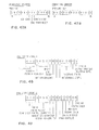
- Fig. 56 shows the layout of the Read Only Storage (ROSO and Random Access Memory locations in the Communications Adapter.
- addresses are shown as they would apply in the machine. These are four-digit hexadecimal (Base 16) addresses. The microprocessor uses the three low order digits. The first addresses are 0000 to 0800 which would indicate a 2K or 2048-byte segment of memory. This is executable code containing the main program entry point. From 0800 to 1000, there are multiple segments of code by the same address called "overlays". Each overlay is accessed by an OUT command with a number associated with it. There are five separate-overlays that can be accessed within the addresses 0800 to 1000; the first overlay being the main overlay of 80; the seconde one, overlay 81; the third one, 82; the fourth one, 83; and the fifth one, 84. Only one of these overlays may be accessed at a specific time until another OUT command selects another overlay.
- the addresses 1000 to 1800 are basically still addresses 000 to 800, but serve as data memory versus executable memory. This is where the 2K (2048) bytes of wire image ROS are placed. This is the compressed images used for printing and is where all 16 fonts, or representative images, are stored in the compressed mode to be uncompressed later into Random Access Memory. From 1800 to 1BFF is where the Interface Random Access Memory Buffers are located, Buffer 1 being at 1800, Buffer 2 at 1900. Each buffer is 256 bytes long. No memory is located in locations 1COO to 3000. A select byte called the X-byte, if off, will select locations 0000 to 2000, and if on, will select locations 2000 to 4000.
- the Interface Buffer is selected with the X-byte off.
- the Text Buffer is selected with the X-byte on.
- 3K (3072) bytes of Random Access Memory in which the wire images are built from the 2K bytes of wire image ROS located at 1000.
- the addresses from 3000 to 38FF are the addresses used for all wire images.
- the subsystem is using three digits, which would be 000 to 8FF in this wire image random access memory. All images are stored as 9 slices.
- the next two digits represent the EBCDIC or Extended Binary Coded Decimal Interchange Code value of the characters as sent over by the host or other source. For example, if the first slice of the letter "C" is required which is an EBCDIC C3, then the subsystem looks in location OC3 for the first slice of the image, 1C3 for the second slice of the image, etc. for the letter "C".
- Fig. 57 basically covers the processing of data going to the CTM 210 or coming from the CTM 210 to the CMM 210.
- the first decision made is, is there data coming from the CTM to be processed; if so, that data is processed and a return is made to the calling operation. If there is no data coming from the CTM, then the question is asked, is there data remaining to be processed by the CTM, which has been sent previously. If the answer is "yes", then a return is made to the calling operation to process that data. If there is no data to be processed from a previous entry, then a check is made to see if there is data to be sent to the CTM presently. If there is nothing to send, then a return is made to the calling operation. If data is to be sent to the CTM, the data is picked up and placed on the buses over to the CTM and returned to the calling operation.
- Fig. 57 represents the operations to process data. For example, if a buffer has been built from data sent from the host system of Fig. 1, then the information is passed to the CTM as to which text buffer is to be printed, at which density it is to be printed and the count of characters to be printed. If it's a forms command, then the number of emitters that the forms are to move are sent in this command. It is a means of communicating between the two microprocessors.
- Operations are now described that enable the storage of a multiplicity of language fonts in limited memory space.
- the operations feature the storage and accessing of present and future character fonts in the printer in compressed mode and enables expansion of the compressed images to a form necessary for printing of characters.
- the font selection and compression is designed for the printer subsystem so that font control tables in storage may have their contents replaced with a new font design without any requirement for microcode change.
- Fig. 58 illustrates the arrangement of pointer and data tables in a general form while Figs. 59-61 provide more details of the font selection, compression and expansion operation.
- Fig. 58 is a layout of the Read Only Storage wire image tables showing that the first group of tables is for the Multinational master load with a pointer table and a data table.
- the Multinational table is a 192 character font that contains most of the other country images, and they are usually designated as a 92-character set country. This means that not all the images are used in the country loads and the Multinational is a composite of all of these. It thus can be modified to handle whatever is desired for a particular country. All unused ones then are indicated as graphic error images.
- the next table is the Major country, and in the present situation, it is assumed to be the Katakana language. It has its pointer table and data table.
- This second table is called “Major” because it is a major " change to the Multinational. In other words, images are added that are not found in Multinational.
- the third table is called the “Modifications to Master” and has some of the images in the Multinational languages that are moved from one location to another. As an example, the United States uses the dollar sign and Great Britain uses the pound sign in the same storage location. This is called a modification to the Multinational. When a Major Country transfer is involved, such as Katakana, then the appropriate Japanese symbol is used for the money sign. There are two blank areas in Fig. 58 for two other major countries, if desired, in storage.
- Fig. 58 indicates whether the multinational table is to be modified for a Major Country, as described, or for a Modification Country. If the bit is on, the Multinational will be overlaid with a Major Country; if the bit is off, it will be modified from the Master Country. There is also a table which provides the internal representation of the desired country versus external desired country which enables an external country selection of anywhere from zero (0) through (FE) or 254 possible identifiers while internally there is a maximum of 16, (0) through (F) .
- the host machine or internal strapping may require font loading of a particular font during printing.
- Table P3, Fig. 59 contains up to 16 font selections.
- Tables Pl and P2, Fig. 59 contain the pointers to fonts to be selected.
- a base load may be loaded from Tables lA and 1B. These are shown in greater detail in Fig. 60. A decision is now made to see if the base load is required or if another font is selected. If the base load is required, then loading is complete. If not, then the decision is made via Table P2, Fig. 59, to see if the required font is a rearrangement-of images or new images are to be loaded.
- Tables 2A, 2B, and 2C shown in greater detail in Fig. 61, are used.
- Table 2A is a "bit sensitive" table used to select the desired font. If the bit is on in Table 2A, then Table 2B indicates the from/to character image position.
- Tables 2C, lA, 3A, 4A and 5A all use the same format. If the rightmost bit in each byte is off, then the other 7 bits indicate "Move a Byte" from Tables 1B, 3B, 4B or 5B for each bit that was on in the lA, 3A, 4A or 5A Table. If the bit was off, then loading of a blank (00) is indicated. If the rightmost bit is on, then the six middle bits are count bits. If the leftmost bit is off, then the count is Skips for loading. If the leftmost bit is on, then the count is Skips for loading and Required Graphic Error Image load on the second pass.
- Table 2C is now used as a second pass to place the graphic error character in the proper image locations.
- Tables 3A and 3B, or 4A and 4B or 5A and 5B are utilized. These will load in two passes using the procedure described above. The first pass loads the images while the second pass inserts the proper graphic error images.
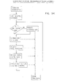
- Figs. 62A-62C illustrate three related operations.
- the first one is a multiple entry operation, Fig. 62A.
- the first entry is for swapping to the next Text Buffer.
- the Pointer is selected for the next Text Buffer; then, the second entry point is available. This entry point is for blanking the presently selected Text Buffer.
- the next Text Buffer is selected and the operation is at the Text Buffer just used to blank it. Blank characters are stored in the current Text Buffer and then a return is made to the calling operation.
- the next operation, Fig. 62B is a save overlay operation which allows a return back in an overlay when another overlay has been selected. This makes use of a stack of three pointers and upon entry moves the top two pointers down one and places the current overlay pointer on the top and then returns to the calling operation.
- the reverse operation of this save operation is a return operation, Fig. 62C, which reads the top of the three pointer stack and then selects that particular overlay that was on top of the stack. After this overlay has been selected, the stack is now moved up, or the bottom two pointers are moved up one in the stack and a return is made to the calling operation.
- Fig. 63 illustrates the scheme used to create wire images for use by the printer by loading characters from the compressed tables.
- the first table is called the Load Table; the second table is the Data Table.
- the Load Table indicates the usage of the data in the Data Table. For example, in the Load Table there is a byte which is broken into eight bits - Bits 0 through 7. If Bit 7 is on and Bit 0 is off, then this byte indicates a Skip Count or the amount of characters to skip before coming to the next one.
- Bits 1 through 6 are the count bits where bit position 6 has a value of 1; bit position 5 has a value of 2; bit position 4 has a value of 4 and so on until bit position I which has a value of 32. If bit 0 is on along with bit 7 this indicates that there is a graphic error count.
- a graphic error is defined as a character that is not normally printed in the selected font. A good example is the control characters which are 00 through 3F. If printed in transparent mode, which means that they are not decoded into control characters, they are printed as hyphens until the graphic error is changed to some other character. This graphic error character count for loading into the table is the same as the skip count.
- bits zero through 6 indicate whether the data from the data table is loaded or whether a blank or zero is loaded for the slices of the vertical sections of a particular image for a character coming from the data table or coming as blanks.
- An example is a byte which has a value of '9A' or 1001 1010; this indicates that slice 1 and slice 9 are already blank due to blanking of the complete character image or font storage area in the random access memory. With this example, the second byte for the slice of that particular character would come from the Data table.
- next two slices are loaded as blanks; the following slice for the fifth slice would be from the Data table; the sixth slice, from the Data table; the seventh slice would be blank and the eighth slice would be from the Data table.
- four slices have been loaded from the Data table to create a total of nine slices for the full image.
- This compression scheme allows all the images to be compressed into one 2K (2048) byte area of Random Access or Read Only Storage.
- the command string shown in Fig. 64 selects 1 of 16 predetermined character sets that the printer subsystem uses to print data.
- This formatting command is called the Set Coded Graphic Character Set (CGCS) through Local Identification (ID) command.
- the first frame (hex 2B) designates the sequence as a formatting command string.
- Frame two (hex D l) is the command class.
- Frames three (hex 03) and four (hex 81) are the command type.
- the fifth frame (Pl) is the code for a designated character set.
- the printer subsystem loads this character set from permanent storage into the print image buffers. All print data uses the stored character set until it is changed by another Set CGCS through Local I D command, a Load Alternate Characters command (described below), or a Power-on Reset command which loads the base character set.
- the Load Alternate character command allows the user to load from 1 to 25 characters into an alternate character buffer.
- the third frame NN is a frame count and must be in multiples of ten (a character image requires 10 frames). It can not exceed 250 (plus I for count frame) to avoid input buffer overrun.
- the data that follows the count frame must be in groups of ten frames with the following organization.
- the following eight frames define the print wires to be activated for the remaining eight vertical columns of the character.
- each print wire is represented by a particular bit in each frame of data. Therefore, a hex 00 will not activate any print wires, a hex 01 activates print wire 8, hex 02 activates print wire 7, and so forth until a hex FF that activates all print wires in a given column of the 8X9 print matrix.
- a hex 42 in frame two causes print wires 2 and 7 to activate in vertical column one of the 8X9 print matrix, as shown in Fig. 67.
- the count frame (NN) equals hex 00, no-operation results. If the count frame is a value that is not a multiple of 10 plus 1 for count frame, zeros (or blanks) are filled in for the right most columns to the next higher multiple of 10. If the count frame is higher than 251, data in excess of 251 frames is disregarded and invalid parameter status is reported. If the value of frame one in the ten frame character image is hex FF, the next nine frames are disregarded and not loaded into the print image buffer.
- Fig. 68 illustrates the process used for loading or reloading of a country font from the compressed Read Only Storage into the expanded Random Access Memory where the Head Image Generator can then read characters to cause the printer unit to print the desired characters.
- the hardware strapping which is set for the particular printer is read. This strapping value is converted to a language font pointer. The question is then asked, "Is this a Multinational Font loading?" The multinational language is the basis for all the loads in the printer subsystem described herein. If the answer is No to Multinational being loaded, then the Random Access Memory is completely blanked and a dash is stored in the Graphic Error Image table, the dash being the normal image used when none other is presented.
- the graphic error image is the image for that particular font that is not defined and not printed.
- the printing for that particular character will be the dash or if another graphic error image is defined, it will be that image.
- the characters are loaded from the Read Only Storage which are in compressed mode and they are expanded into the Random Access Memory and stored. This was described in the loading characters from compressed tables chart (Fig. 63). After the characters are all loaded, the table is then rescanned looking for graphic error image pointers in which the graphic error image is now stored in the Random Access Memory. Then the question is again asked, "Is the Multinational Font Selected?" If it is, the loading is done and a return made to the calling operation.
- Rearrangement means moving a character from one position to another position. An example of that is the use of a dollar sign in a specific location in a printer in the United States where a printer in Great Britain would use a pound sign in the same location. If the answer is No, then new characters are loaded from another selected table and expanded into the Random Access Memory. After all these new characters are stored, again the table is rescanned and graphic error images are selected for that font. Upon completion of this, a return is made to the calling operation.
- this font is not a selected rearrangement of Multinational, then a pointer is set to the To/From table which indicates which character is moved from where to where. Each character is moved from the originating location where it will be used for that font and the question is again asked or is asked, "Are all characters moved for this font?" If No, the characters are moved. If Yes, then graphic error images are again stored for this particular font and a return made to the calling operation.
- the other entry for this load is the reload capability which could be from the SNS or SNA commands to cause a different country to be loaded other than what the strapping is set for.
- the language font pointer Upon entry, the language font pointer is set to that desired font and then the reload location is accessed where the question is asked again, "Is Multinational Font loaded?" This is similar to the question, "What was the strapping for this particular printer?". The operation continues in the same manner.
- Fig. 69 shows the printing from the Interface Buffer with embedded control codes.
- a code to change the image of a character is demonstrated by a simulated interface buffer with data.
- the buffer starts with a (15) which is interpreted as a New Line control character that causes the printer wherever it is to go to the next line at the start of the line.
- the next control sequence, (2B Dl 03 81 01) is interpreted as a Load United States/Canada Font into the wire image Random Access Memory. Following this, there are two (40) which are interpreted as printing a blank.
- a ? (5B) is next and under the United States/Canada Font prints will'print a dollar sign.
- the next four characters which are (F3 FB F7 F5) will print in sequence a three, period, seven, five (3.75) with the total characters being printed as "$3.75".
- Next in sequence are three (40) commands which are three blank spaces.
- Another control sequence to modify the font This is (2B Dl 03 81 OF) which causes a loading of the United Kingdom font.
- a (5B) is printed as done previously, but since the United Kingdom font was loaded, (5B) is now a pound sign instead of a dollar sign. This is the next printable character that is printed.
- the following four characters (F2 4B F2 F5) which causes a "2.25" to be printed after the pound sign.
- the next control command sequence is a sequence to cause the image in the Random Access Memory for location (5B) to be modified to a diamond image.
- This sequence is (2B FE OC 01 5B 00 10 28 34 AA 34 28 10 00).
- the last nine bytes are the characters that cause the dots to be generated in the diamond image.
- the following character is a 40 which will print as a blank.
- the (5B) is printed again which prints as a diamond. This finishes the sequence of this particular buffer that has been simulated.
- the printed page has seventeen characters printed in one line. These are actually printed in three separate passes on that particular line by the print head. Below the printed results are an enlarged picture of the generation of the diamond image. This shows how the diamond is created from the control code in the Interface Buffer.
Abstract
Description
- The invention relates to a font selection and compression device for a printer subsystem interconnected with a host system this device enabling storage and selection of a multiplicity of fonts in limited memory space.
- In prior dot matrix printers of the type described in US-A-4.159.882 (R.C. Sanders et al) published July 3, 1979, storage means are provided to store multiple character fonts. The printer prints the dot patterns of the characters using a multi-wire printing head and a selected font image set in storage.
- In the prior printers, selection of the fonts has been on a somewhat limited and highly selective basis. That is, it has been customary for any individual printer subsystem to have only one or several fonts available and these are usually prewired into the system for each individual customer. The customer has not been able to expand the range of languages or special symbols that he might require during normal printer operations without extensive reworking of the font selection means, a service call, and the like. Where font selection has been available, the storage required for the fonts has been rather extensive.
- In accordance with the present invention, storage facilities are provided for a printer subsystem, the storage facilities 'being preloaded with a large number of font images arranged generally in accordance with individual languages accessible by the printer subsystem on a real time basis as printing operations proceed. With this arrangement, it is possible to print more than one language in individual lines of characters with a rapid switchover from one language to another in a manner that the switchover is hardly noticeable by the user. In addition, special symbols are accommodated. That is, the customer may require symbols that are unique to his particular printing operations and that are ordinarily not encountered by any other customer. In addition, the font storage is on a compressed basis, that is numerous font images are stored in a relatively limited amount of storage space by a compression technique. In most cases, the printer subsystem is loaded with a "base" font image set that is the normal font image used by the particular printer subsystem. As operations proceed, the "base" image can be replaced by other font images. After use of the other font images, the printer subsystem ordinarily returns to the base font image set. The fonts are stored in selected areas of a read only storage, the images being accessed during printer operations as required for generation of wire images in the printer unit. Pointer tables and data tables are used for the base font images, modifications for the base font images, and alternative font images that may be selected by the subsystem.
- For a better understanding of the present invention, together with other and further advantages and features thereof, reference is made to the description taken in connection with the accompanying drawings which illustrate one specific embodiment.
- Referring to the drawings:
- Fig. 1 is a simplified system diagram for the printer subsystem.
- Fig. 2 illustrates the printer console and a number of printer components as well as forms feeding. 0
- Fig. 3 is a frontal view of the printer unit in the printer console of Fig. 2.
- Fig. 4 illustrates an operator panel useful with the printer of Figs. 1 and 2.
- Fig. 5 shows a mode switch for control of on-line, off-line conditions.
- Fig. 6 shows a gate assembly with printed circuit cards.
- Fig. 7 is a frontal view of the printer console of Fig. 2 with the cover open showing a print emitter.
- Fig. 8 is an exploded view of various printer assemblies including the forms feed assembly, the print assembly and the ribbon drive assembly.
- Fig. 9 is a cross-sectional view at the print line of the printer of Figs. 2, 3, and 8.
- Fig. 10 is a right side elevation of various printer assemblies shown in Fig. 8.
- Fig. 11 is a view of a ribbon shield having a print aperture positioned in a horizontal plane.
- Fig. 12 is a cross-sectional view of the ribbon shield on the lines 12-12 in Fig. ll.
- Fig. 13 is an overhead view of the printer slightly from the rear of the unit showing the forms feed open.
- Fig. 14 illustrates a print wire block assembly and associated guide.
- Figs. 15 and 16 illustrate front and rear faces of the guide shown in Fig. 14.
- Figs. 17-19 illustrate an alternative mounting of print wire actuators with an angled face on the block assembly.
- Figs. 20-22 illustrate mounting of print wire actuators with a flat face the actuator block assembly.
- Figs. 23-26 illustrate a print wire actuator, a plurality of which are mounted in the block assembly shown in Fig. 14.
- Figs. 27 and 28 illustrate an alternative forms feed assembly for the printer unit.
- Fig. 29 illustrates the arrangement of print wires in groups relative to a left margin in the printer unit.
- Fig. 30, illustrates printing of characters at 10 characters per inch and 15 characters per inch.
- Figs. 31 and 32 illustrate the print emitter and its operating scheme.
- Figs. 33A and 33B, when arranged as shown in Fig. 34, show in greater detail the relationship of the print wires to character locations on the forms to be printed.
- Fig. 35 is a generalized block diagram of the printer control unit shown in Fig. 1.
- Figs. 36 and 37 further illustrate the arrangement of dots to form characters and the relationship of the print wires to the various character locations.
- Figs. 38-40 illustrate various systems in which the printer subsystem may be connected.
- Fig. 41 illustrates a stream of information between the host system and the printer subsystem.
- Fig. 42 illustrates significance of bits in the frames during a receive mode when information is transferred from the controller to the printer subsystem.
- Fig. 43 illustrates bit significance for the frames during a transmit mode when information is transferred from the printer subsystem to the controller.
- Fig. 44 illustrates the bit configurations for printer addressing.
- Fig. 45 shows command and data arrangements in the information stream.
- Fig. 46 is a chart illustrating a typical transfer of data to be printed.
- Figs. 47A and 47B illustrate representative operational and formatting commands.
- Figs. 48 and 49 illustrate frame layout for status reports during a Poll operation.
- Fig. 50 is a block diagram of various circuit components used in the printer subsystem of Figs. 1 and 2.
- Figs. 51A and 51B, when arranged as shown in Fig. 52, comprise a block diagram of the printer control unit including a Communications microprocessor (CMM) and a Control microprocessor (CTM) as well as a number of elements in the printer unit.
- Fig. 53 illustrates a typical data transfer and printing operation in the printer subsystem.
- Fig. 54 is a generalized flowchart of operations for the Communications microprocessor (CMM) shown in Fig. 51A.
- Fig. 55 is a generalized flowchart of operations for the Control microprocessor (CTM) shown in Fig. 51B.
- Fig. 56 illustrates the layout of Read Only Storage and Random Access Memory used in conjunction with the communications microprocessor.
- Fig. 57 illustrates the operations performed transfering information between the communications microprocessor and the control microprocessor in the printer subsystem.
- Fig. 58 is a generalized representation of the font storage and selection scheme used herein.
- Figs. 59-61 are more detailed representations of the scheme shown in Fig. 58.
- Figs. 62A-62C illustrate related operations involving the selection and blanking of the text buffers as well as saving and return to the overlays.
- Fig. 63 illustrates loading of characters from compressed tables.
- Fig. 64 illustrates the formatting command for Coded Graphic Character Set (CGCS) word to change font images.
- Figs. 65-67 show various aspects of a Load Alternate Character operation.
- Fig. 68 illustrates the operation for font selection and modification.
- Fig. 69 illustrates the printing of characters in a line of information involving a font image change and selection of a special image.
- In order to best illustrate the utility of the present invention, it-is described in conjunction with a high speed matrix printer, typically capable of printing in a high range of lines per minute on continuous forms. The particular printer subsystem described herein is associated with a host system or processor, responds to command and data signals from the host to print on the forms and in turn provides status signals to the host during operations.
- The printer itself is an output line printer designed to satisfy a variety of printing requirements in data processing, data collection, data entry, and communications systems. It can be used as a system printer or a remote work station printer.
- The following printer highlights are of interest:
- Print density of 10 or 15 characters per inch (25,4= mm) selectable by the operator or by the using system program;
- Condensed print mode, 15 characters per inch saves paper costs and makes report handling, mailing, reproduction, and storage easier;
- Line spacing of 6, or 8 lines per inch or any other line density selectable by the operator or by the using system program;
- Incremental and reverse forms movement selectable by the using system program;
- Sixteen self-contained character sets selectable by the using system program with a base language selected by hardware jumpers.
- Special graphics ability (special characters, graphs, plotting, etc.) selectable by the using system program;
- Matrix printing technology;
- Built-in diagnostics for problem determination by the operator;
- Microprocessor control unit;
- Maximum print line width - 330,2 mm.
- Maximum print positions for 10 characters per inch - 132;
- Maximum print positions for 15 characters per inch - 198;
- Adjustable forms width - 76,2 to 450 mm;
- Maximum forms length - 76,2 to 317,5 mm;
- Fig. 1 illustrates a representative system configuration including a
host system 1 and theprinter subsystem 2 which includes aprinter control unit 3 andprinter electronics 4. Command and data signals are provided by the host system by way ofinterface 5, and command and control signals are provided from printer control unit 3-to theprinter electronics 4 by way ofbus 6. Status signals are supplied byprinter control unit 3 to host system I by way ofinterface 5. Typically, thehost system 1 generates information including commands and data and monitors status.Printer control unit 3 receives the commands and data, decodes the commands, checks for errors and generates status information, controls printing and spacing, and contains printer diagnostics.Printer electronics 4 executes decoded control unit commands, monitors all printer operations, activates print wires, drives motors, senses printer emitters, and controls operator panel lights and switching circuitry. It controls the tractor/platen mechanism, the ribbon drive, the print head (i.e., actuator group) carrier, the operator panel, and the printer sensors. - The elements of the system, such as the printer control unit and printer electronics, incorporate one or more microprocessors or microcomputers to analyze commands and data and to control operations.
- Figs. 2 and 3 illustrate various components of the printer all of which are housed in the
console 10. Various access panels or covers such as those designated 11, 12, and 13 are provided.Top cover 11 has awindow 14 that enables an operator to observe forms movement during operation of the printer and when the cover is closed. Forms (documents) 15 are provided from astack 16 and can be fed in one embodiment upwardly or downwardly as viewed in Figs. 2 and 3 by means of aforms feed assembly 20 which includes one or more sets of forms tractors such as the upperset comprising tractors print assembly 30 that is positioned generally in a horizontal relationship with respect toforms 15 at aprint station 32.Print assembly 30 is more clearly visible in other views. This is also true of the printerribbon drive assembly 40 which is located in closer proximity to the front of the printer.Printer control unit 3 and its associated microprocessors are generally located behind theside cover 13. - As best seen in Fig. 3, a
ribbon 41 is provided on one of thespools disposable ribbon shield 46 that fits betweenprint assembly 30 andforms 15 to keepribbon 41 in proper alignment and to minimize hold ink smudging onforms 15. Two motors shown more clearly in Fig. 8drive ribbon 41 back and forth betweenspools - The printer includes an operator panel 26 (shown in greater detail in Fig. 4) that consists of several operator control keys (pushbuttons 51-55 and 60), two
indicator lights switch 58, and anoperator panel display 59. By using various combinations of the keys in conjunction with theshift key 55 the operator can:start or stop printing and view the last line printed, set print density, position the forms up or down one page or one line at a tine, move the forms incrementally up or down for fine adjustment, and start or stop the diagnostic tests when selected by a mode switch, to be described. - The indicator lights on the operator panel display notify the operator that:the printer is ready to print data from the using system (indicator light 57), the printer requires attention (indicator light 56), the current print density seating (panel display 59), errors, if any, have been detected, and the results of the diagnostic tests (panel display 59).
- A 16-
position mode switch 65 is located behind thefront door 12 and is shown in greater detail in Fig. 5. The on-line positions permits printing to be controlled by the using system. All other positions are off-line and do not allow printing to be initiated from the using system. - The first two switch positions are used by the operator to select these modes:
- On-line. The normal operating position. With the switch in this position, the printer accepts commands from the using system. The
operator panel display 59 indicates any detected error conditions. - Buffer Print. An additional on-line position which prints the EBCDIC values (hexadecimal codes) sent from the host and the associated character images. No control characters are interpreted. This feature allows the user to view the data stream sent to the printer.
- Test. For off-line checkout and problem determination. In test mode, when Start key 53 is pressed, the
Attent indicator 56 stays on andReady indicator 57 is turned on until the diagnostic tests that are stored in the printer control unit are finished or the Stop key is pressed. If an error is detected, the printer stops and displays an error code in theoperator panel display 59. - The remaining thirteen (13) positions of the mode switch designated "2-9" and "A-E" are used by service personnel to select a variety of diagnostic tests to aid in off-line problem determination and confirmation of service requirements.
- Fig. 6 illustrates a
gate assembly 17 located behindside cover 13, Fig. 2, the gate assembly including modular printed circuit cards such ascards 8 that contain much of the circuit elements forprinter control unit 3 andprinter electronics 4, Fig. 1. - Fig. 7 is a frontal view of a
print emitter assembly 70 that includes anemitter glass 71 and anoptical sensor assembly 72.Glass 71 is vertically positioned with respect tosensor assembly 72 and is mechanically attached toprint mechanism 30 so that as the print heads, print actuators, and print wires move back and forth left to right and conversely as viewed in Fig. 7,glass 71 also moves in the same manner with respect tosensor assembly 72 to indicate horizontal position of the print wires.Cabling 73 supplies signals to the print actuators which are described in detail below. - Figs. 8, 9 and 10, among others, show the detail of construction of the forms feed
assembly 20, theprint assembly 30, theribbon drive assembly 40, and various associated emitters. A general overview of these assemblies is first presented. - As best seen in Figs. 8 and 10, forms feed
assembly 20 has end paltes (side castings) 21 and 22 which support the various forms feed mechanisms including adrive motor 23 to drive tractors 90-93, the motor having a forms feedemitter assembly 24. The forms feed assembly has a separate end of forms andjam detector emitter 25.Assembly 20 also includes aplaten 29 located behind the forms and against whi;h theprint wires 33 are actuated during printing (See Fig. 9). - The
print assembly 30 includes a base casting 75 supporting various mechanisms includingprint motor 76, shown in phantom in Fig. 8 in order that other elements may be seen more easily, and connected to drive aprint head carrier 31 withactuator block assembly 77 in a reciprocal fashion horizontally to effect printing on an inserted form. The print assembly also drives theprint emitter assembly 70 havingemitter glass 71 andoptical sensor assembly 72. - The
ribbon drive assembly 40 includes a support casting 44, acover 45, and drivemotors - In order to load paper in the printer the forms feed
assembly 20 pivots away from the base casting 75 at pivot points 80 and 81, the latter pivot point being best seen in Fig. 10, to allow access to thread the forms into position.Latches extremities eccentric pins latches tang 95 on forms feedassembly 20 when it is closed. Referring to Fig. 8, the forms feed assembly includes means for adjusting for forms thickness. As mentioned, the entire forms feed assembly pivots back from the rest of the printer about pivot points 80 and 81. In the closed position the forms feed assembly is in such a position that aspiral cam 96 engages apin 97 on themain carrier shaft 98 of the print assembly 30 (see also Fig. 9). Adjustment of the spiral cam andknob assembly 96 is such that it rotates themain carrier shaft 98.Assembly 96 is retained in position by a spring loaded detent assembly. This has a spring loaded pin which engages notches in the knob so that it is held in the position set by the operator. Associated withshaft 98 are eccentrics such asportion 98a on the left end of shaft 99 withtenon 100 onto which latch 83 is mounted. Rotation ofshaft 98 thus moves latches 83 and 84 which changes the distance betweenassemblies print wires 33 andplaten 29. This adjustment enables the printer to accomodate forms of various thicknesses. The printer can handle forms from one part to six parts thickness. - The paper feeding is accomplished by the four sets of tractors 90-93 two above the print line and two below the print line. The individual tractors include drive chains to which pins are attached at the proper distance to engage the holes in the form. As an example,
tractor 90 hasdrive chain 101 withpins 102.Chain 101 is driven by asprocket 103 attached to ashaft 104 which also drives the sprocket and chains fortractor 91.Tractors shaft 105. Because the tractors are above and below the print line, the printer is able to move the paper in either direction. The normal direction of forms drive is upwardly in Figs. 3 and 8. However, it is possible to move the paper downwardly, as well. - Rotation of
shafts motor 23 in the proper direction which in turn drivespulleys 106 and 107 (to whichshafts motor pulley 108 by means of drive-timing belt 109. Cover 110 coversbelt 109 and pulleys 106-108 during rotation. The forms feedemitter assembly 24 includes anemitter wheel 47 with marks to indicate rotation and a light emittingdiode assembly 48 that serve to indicate extent of rotation ofmotor 23 in fi either direction and as a consequence, the extent of movement of the forms as they are driven bymotor 23. - The capability of the printer to feed paper in both directions offers some advantages. For example, in order to improve print visibility at the time the Stop button is pushed by the operator, the paper may be moved up one or two inches above where it normally resides so that it can be easily read and can be easily adjusted for registration. When the Start key is depressed, the paper is returned to its normal printing position back out of view of the operator. The printer may also be used in those applications where plotting is a requirement. In this case a plot may be generated by calculating one point at a time and moving the paper up and down much like a plotter rather than calculating the entire curve and printing it out from top to bottom in a raster mode.
- End of forms and jam detection is accomplished in this assembly by a
sprocket 112 just above the lower left tractor. The teeth in this sprocket protrude through a slot 113a in theflip cover 113. This sprocket is not driven by any mechanism but simply is supported by a bearing. The sprocket engages the feed holes in the paper as it is pulled past by the tractor assemblies. On the other end of theshaft 114 from the sprocket is a smalloptical emitter disc 115. The marks in this disc are sensed by anLED phototransistor assembly 116 and supplied to the electronics of the subsystem. The electronics verifies that marks have passed the phototransistor at some preselected frequency when the paper is being fed. If the mark is not sensed during that time, the machine is shut down as either the end of forms has occurred or a paper jam has occurred. - The
castings 88 and 89 supporting the tractors 90-93 are adjustable left or right in a coarse adjustment in order to adjust for the paper size used in a particular application. After they are properly positioned they are locked in place onshaft 67 by locking screws such as lockingscrew 87. - All tractors are driven by the two
shafts motor 23 as previously described. The motor adjusts in the side casting 21 inslots 120 in order to provide the correct tension forbelt 109. - Besides the coarse adjustment, there is also a fine adjustment which is used to finally position in very small increments laterally the location of the printing on the forms. This is done by a threaded
knob 66 which engagesshaft 67 to which both tractor castings clamp. This shaft floats betweenside castings knob 15 engage threads on the right end ofshaft 67. The knob is held in a solid position by afork 68. Thereforeknob 66 stays stationary and the threads driving through theshaft force shaft 67 laterally left or right, depending upon the direction in whichknob 66 is rotated.Shaft 67 is always biased in one direction to take out play by aspring 69 on the left end of shaft. As the paper leaves the top of the tractors, it is guided up and toward the back of the machine and down by thewire guide 28. - In order to insure that the distance between the pins in the upper tractors is in correct relationship to the pins in the lower tractors an adjustment is performed. This adjustment is made by inserting a gauge or piece of paper in the tractor assembly which locates the bottom pins in the correct relationship to the top pins. This is done by loosening a
clamp 121 on the end ofshaft 104. Once this position is obtained, then clamp 121 is tightened and in effect phases the top set of tractors to the bottom set so that holes in the paper will engage both sets of tractors correctly. Forms may be moved through the tractor forms feed mechanism manually by rotatingknob 122. This knob simply engages thetop drive shaft 104 of the upper tractor set and through thetiming belt 109 provides rotational action to the lower tractor set, as well. - In Fig. 8, a
carrier 31 comprisingactuator block 77 andsupport 78 accommodate all the print heads with theirwire actuators 35 andprint wires 33. Also, see Figs. 13 and 14-26.Actuator block 77 is designed to hold from two up to eight or nine print head groups of eight actuators each. Thus, a printer with eight print head groups, as shown in Figs. 8 and 13, has sixty-four print wire actuators and sixty-four associated print wires. Only twoactuators 35 are shown positioned in place in Fig. 8. The other sixty- two actuators would be located inapertures 133 only a few of which are depicted. To insure long life of the print wires,lubricating assemblies 134 containing oil wicks are positioned in proximity to the print wires. The print wire actuators fire the wires to print dots to form characters.Carrier 31 is shuttled back and forth by alead screw 36 driven bymotor 76. Leadscrew 36 drives the carrier back and forth through nuts which are attached to the carrier. Whencarrier 31 is located at the extreme left, as viewed in Figs. 3 and 8 (to the right as viewed in Fig. 13), this is called the "home position". When the carrier is moved to the home position, acam 37 attached to the carrier engages apin 38, the pin being attached to themain carrier shaft 98. If the machine has not been printing for some period of time, in the neighborhood of a few seconds, the printer control unit signals the carrier to move all the way to the left, in whichcase cam 37 engagespin 38 to rotate themain carrier shaft 98 approximately 15 degrees. On each end of the shaft are the eccentrically located tenons, such astenon 100, previously described. These tenons engage thelatches shaft 98 rotates, the eccentrics associated withlatches - The purpose of
motor 76, of course, is to move thecarrier 31 back and forth in order to put theprint actuators 35 andprint wires 33 in the proper positions to print dots and form characters. Since the motion is back and forth, it requires a lot of energy to get the mass ofcarrier 31 andactuators 35 stopped and turned around at the end of each print line. A brushless DC motor is used. The commutation to the windings in the motor is done external to the motor through signals sent out of the motor via a Halleffect device emitter 39. In other words, theemitter 39 within the motor sends a signal out telling the printer control unit that it is now time to change from one motor winding to the next. Therefore, there are no rubbing parts or sliding parts within the motor, and switching is done externally via electronics based on the signals that the motor sends out from its emitter. The motor draws about 20 amperes during turnaround time and, because of the high current it draws and because of the torque constant required from the motor, it is built with rare earth magnets of Samarium cobalt which' provide double the flux density of other types of magnets. - Samarium cobalt is not just used because of the higher flux density but also because its demagnetization occurrence is much higher and, therefore, more current can be sent through the motor without demagnetizing the internal magnets. During printing,
carrier 31 that holds theprint actuators 35 goes at a velocity of approximately 63,5cm per second. - The turnaround cycle at the end of the print line requires 28 milliseconds approximately, resulting in a Gravity or "G" load in the neighborhood of 4 G's. The carrier, with all the actuators mounted, weighs about 3,85 Kg.
- The current necessary to fire the print actuators is carried to the actuators via the
cable assemblies 73, Figs. 7 and 13, one for each group of eight actuators. The cabling, such as cable 73a, Fig. 8, is set in the machine in a semicircular loop so that ascarrier 31 reciprocates it allows the cable to roll about a radius and therefore not put excessive stress on the cable wires. This loop in the cable is formed and held in shape by asteel backing strap 74. In this case there is one cable assembly for each group of eight actuators or a maximum of eight cable backing strap groups. - The
ribbon drive assembly 40 for the printer is shown in Fig. 8, but reference is also made to Figs. 3, 9, and 13.Spools Gear flanges spool 43, as an example, is frommotor 50,pinion gear 132 to a matching gear 119a formed on the underneath side ofgear flange 119 then to spool 43. In one direction of feed, the ribbon path is from the left-hand spool 42past posts forms 15, then pastposts hand ribbon spool 43. Aribbon shield 46 to be described in conjunction with Figs. 11-13 is generally located betweenposts 126 and.127 and is mounted on the twoattachment spring members - Fig. 11 illustrates
ribbon shield 46 that is particularly useful in the printer described herein. Fig. 12 is a cross-sectional view along the lines 12-12 in Fig. ll.Shield 46 has an elongated aperture 46a extending almost its entire length. The aperture enables theprint wires 33 to press against the ribbon in the printer through the shield in order to print onforms 15.Shield 46 hasslits 46b and 46c at opposite extremities to permit easy mounting in the printer onspring members - Fig. 13 is an assembly view of the printer including forms feed
assembly 20,printer assembly 30, andribbon drive assembly 40.Ribbon drive assembly 40 includes the two ribbon spools 42 and 43 which alternatively serve as supply and takeup spools. Ifspool 42 is serving as the supply spool,ribbon 41 will be suppliedpast posts ribbon shield 46past posts takeup spool 43.Shield 46, Figs. 11 and 13, andribbon 41, Fig. 13, are illustrated slightly on the bias relative to horizontal which is their more normal relationship in the printer. Theribbon drive assembly 40 is also positioned on a slight bias relative to horizontal to accommodate the bias ofshield 46 andribbon 41. In this condition aperture 46a assumes a horizontal relationship with respect to theprint wires 33 and forms 15. - Thus, in Fig. 13, the rightmost end of
shield 46 is somewhat elevated in relation to the leftmost end in order that aperture 46a is maintained in a relatively horizontal position with respect to the print actuators inprint mechanism 30. A few of the groups ofprint wires 33 are indicated at a breakaway section ofshield 46. As previously noted, the print wires are reciprocated back and forth laterally in relation to a form, not shown in Fig. 13, in order to effect the printing of characters. The reciprocation is by means of drive mechanisms activated frommotor 76. The activating signals for the actuators inprint mechanisms 21 are supplied through cabling indicated at 73. - Enlarged views of the
actuator block 77, guide 79,print wire actuators 35,lubricating assemblies 134, and various related mechanisms are shown in Figs. 14-23. Referring to Fig. 14, this better illustrates the arrangement ofapertures 133 inactuator block 77 which can accommodate eight print heads with eight print wire actuators. Apertures 133a are used to mountactuators 35 while apertures 133b allow passage ofbarrels 136 ofactuators 35 throughactuator block 77 and guide 79 up to the print line. Atypical lubricating assembly 134 comprises acover 140, feltelement 141,wick assembly 142, andhousing 143 that contains lubricating oil. - Fig. 15 illustrates a portion of face 79a of
guide 79 while Fig. 16 illustrates a portion offace 79b ofguide 79.Barrels 136 ofactuators 35 pass throughapertures 145 on face 79a ofguide 79 and are retained by bolts such asbolt 146 passing throughapertures 147 from the opposite side ofguide 79. Individual actuator barrels 136 andprint wires 33 project throughapertures 148, Figs. 13 and 16. - Figs. 17-22 illustrate several arrangements which permit mounting of a greater multiplicity of actuators in a given amount of space through
actuator block 77 andguide 79. Figs. 17-19 illustrate one possible mounting arrangement for the actuators while Figs. 20-22 illustrate the actual mounting arrangement previously described in conjunction with Figs. 8, 13, and 14-16. - In Figs. 17-19 which represent an alternative mounting arrangement,
print actuators 35a andprint wires 35 for one print head set of eight (1-8) are arranged on astraight slope 150. This slope, combined with actuator block 77a having a double angle configuration at 151, Fig. 18, results in a staggered print wire face-to-platen condition, Fig. 19. This print wire face-to-platen distance, shown as 8X, is critical to both the stroke and flight time of the print wires. - The preferred arrangement, Figs. 20-22, has a number of attributes, including improved functioning, increased coil clearance, and ease of manufacture. In this method,
print wires 35 arranged in a set 1-8 are mounted in two offset slopedsubsets subset 152b includes print wires 5-8. This, combined with astraight surface 153 onactuator block 77 andangled actuators 35, Fig. 21, represent an in-line print wire face-to-platen condition as in Fig. 22. The print wire face-to-platen condition as in Fig. 22. The print wire face-to-platen distance, shown as X, is at a minimum. This permits a higher printing rate and prevents wire breakage. The offset sloped print wire sets gives a greater clearance between wire positions which allows a larger actuator coil to be used. - Use of a
straight surface 153 instead of thedouble angle 151 facilitates manufacturing of the actuator block and thereby reduces cost. However,brackets 155 are still cut at an angle such as shown in Fig. 24. The angular relationships of theprint actuators 35a with respect to the platen faces in Fig. 18 andprint actuators 35 with respect to the platen face in Fig. 21 are somewhat larger than would be encountered in an actual implementation but they are shown this way to make the relationships easier to see. In contrast, an actual angular relationship might be smaller such as the 4° 30' angle front face 155a onbracket 155 ofactuator 35 in Fig. 24. - Figs. 23-26 illustrate a preferred form of
actuator 35. A print wire is provided having an armature which is retained in home position by a permanent magnet. When printing of a dot is required, an electromagnet is energized which overcomes the magnetic forces of the permanent magnet and propels the print wire toward the paper. - Fig. 23 illustrates one side elevation of the actuator, while Fig. 24 illustrates the opposite side elevation. The actuator comprises a number of elements arranged in a generally concentric manner on
bracket 155. It is noted that Fig. 24 is somewhat enlarged relative to Fig. 23. Reference is also made to Figs. 25 and 26 for details of the individual components of the actuator. Also, it is noted that some slight structural differences appear between the actuator shown in Figs. 23-26 and those illustrated in Figs. 17-22, the actuators in Figs. 17-22 being more diagrammatically illustrated. The actuator includes abarrel 136 for supportingprint wire 33 in proper relationship for printing when mounted inactuator block 77 andguide 79. Attached to the leftmost end ofprint wire 33 as viewed in Fig. 25 is anarmature 156 which is arranged against a stop portion 156a of anadjustment screw 157 by forces exerted from apermanent magnet 158. Alock nut 159, Fig. 23, retainsadjustment screw 157 in proper position. Thus, when not active,armature 156 andprint wire 33 abut against stop 157a. When it is desired to actuateprint wire 33,electromagnet 160 is rapidly impulsed from an external source by way ofconnectors 161. Energization ofcoil 160 overcomes the magnetic flux forces ofpermanent magnet 158 movingarmature 156 andprint wire 33 to the right as viewed in Fig. 25 thus causing the rightmost end ofprint wire 33 which is in proximity to the forms, to print a dot on the forms. Abobbin housing 162 is made of metallic substances to provide a shielding effect with respect toelectromagnet 160. It is found that this has been beneficial when numerous print wire actuators are mounted in position onactuator block 77 and guide 79 since it prevents stray impulses from reacting from one actuator to another nearly actuator. This has proven to be extremely advantageous when multiple print actuators are provided as in the present printer. Acore element 163 provides a forward stop location forarmature 156 in readiness for restoration bypermanent magnet 158 against stop 157a as soon as current is removed fromcoil 162. - Figure 26 is an end elevation of
housing 162 along the lines 26-26 in Figure 25. - Figs. 27 and 28 illustrate an alternative single direction forms feed
assembly 170 which feeds forms only in the upward direction as viewed in these figures. In contrast with the forms feed assembly previously described in conjunction with Fig. 8, this forms feed assembly has only a single upper set oftractors motor 173 provides driving force throughgears timing belt 178. The various elements comprising the forms feed assembly are supported in aleft end plate 180 and a right end plate 181. Fig. 28 is a left end elevation of the forms feedassembly 170 illustrating the positional relationships ofmotor 173,timing belt 178 and other elements. Acover plate 182 coverstiming belt 178 during operations. Driving of the pin feeds on the twotractors assembly 20 illustrated in Fig. 8 and previously described. In forms feedassembly 170, the tractor drive includes adrive shaft 183. - Lateral support for the forms feed
assembly 170 is provided by anupper support 185 and alower support 186. The assembly also includes a platen member 29a. Other elements such asknobs counterpart elements - In place of the two
lower tractors pressure drag assembly 188 withcompliant fingers 189. These fingers exert physical pressure against the paper when.in position against platen 29a and in the immediate vicinity of the printing station. - At the same time that forms
feed assembly 170 is opened for insertion of new forms, thedrag assembly 188 is also opened, but while the forms feed assembly moves toward the rear of the printer, the drag assembly moves toward the front.Spring element 187 enablesdrag assembly 188 to adjust to allow the forms to slide through when loading the forms. Oneadditional cam element 190 cooperates with afollower 191 to provide adjustment of the pressure exerted by thedrag assembly 188 on the paper for the purpose of accommodating various thicknesses of forms. - The assembly includes an End of Forms sprocket assembly 192 that could also serve to detect paper jams and that works in an analogous fashion to
assembly 25 withsprocket 112 shown in Fig. 8. - Characters that are printed are formed by printing dots on the paper. These dots are printed by wires that are mounted in groups of eight on a carrier bar that moves back and forth adjacent to the print line. Printing is bidirectional with complete lines of print formed right-to-left and left- to-right. See Figs. 29, 30, 33A and 33B.
- A character is formed in a space that is eight dots high by nine dots wide. As shown in Fig. 30, two of the nine horizontal dot columns (1 and 9) are for spacing between characters. Any one wire can print a dot in four of the seven remaining horizontal dot positions (2 through 8). The printer can print 10 characters per inch or 15 characters per inch.
- Most of the characters printed use the top seven wires in the group to print a character in a format (or matrix) that is seven dots high and seven dots wide. The eighth (bottom) wire is used for certain lower case characters, special characters, and underlining.
- The number of print wire groups varies according to the printer model, and typically can be 2, 4, 6 or 8 groups. Printing speed increases with each additional wire group.
- There are 16 character sets stored in the printer control unit. Any of these sets may be specified for use by the using system program.
- Fig. 31 is a representation of the
emitter glass 71 also shown in Figs. 7 and 8 and associated with theprint mechanism 21. It has sections called "Ramp", "Home", and "Left Margin". These are coded sections, designated Track A, Track B, and Track C. Track B is sometimes referred to as the "Turnaround" track. "Home" is indicated by all three tracks being clear. "Ramp" is when Track A and Track C are clear, but Track B is opaque. "Left Margin" is when only Track C is clear, and Tracks A and B are opaque. Left Margin can be told from Right Margin because Track B is clear on Right Margin whereas Track B is opaque on Left Margin. For convenience,glass 71 is shown in a more normal representation with the left margin areas to the left and the right margin areas to the right. In actuality, theemitter glass 71 is physically located in the machine with the right-hand part in Fig. 31 toward the left and the left-hand part in Fig. 31 toward the right as viewed in Figs. 7 and 8. This is due to the fact that the associatedoptical sensor 72 is physically located at the rightmost area of the strip when the print mechanism is in home position, andglass 71 actually is moved past theoptical sensor assembly 72 from left to right as the print mechanism moves from left to right away from home position. - Fig. 3.2 illustrates the development of emitter pulses from the
emitter strip 35 shown in Fig. 31, the signals being termed "real emitters" when actually sensed from Track A. "Option" emitters (sometimes referred to as "false" emitters) are developed electronically in the printer control unit. The use ofemitter 70 in keeping track of printing location is described. The emitter tells the electronics when the wires are in a proper position to be fired to print the dots in correct locations. It essentially divides the print line into columnar segments, each one of which is available to the electronics to lay down a print dot. Track A, the basic track which controls the printing of dots has spacings of 0,56 mm. This corresponds to two print columns distance on the emitter in a normal print cycle and for ten characters per inch one option is inserted halfway in between. - Each emitter track actuates one pair of light emitting diode-photo transistor (LED-PTX) sensors within
sensor assembly 72. Track A provides print initiation pulses, Track B provides turnaround information, and Track C indicates if the print heads are in either left or right margin. - If the line to be printed is shorter than the maximum print line length, typically 330,2 mm, then a signal for turnaround (reversal of
print motor 76 direction) is given as soon as the last character has been printed. The motor now decelerates until it comes to a stop, and then immediately accelerates in the reverse direction until nominal speed is reached. - To keep track of the print head position, the number of emitters of Track A are counted. The A sensor keeps increasing the count regardless of whether the print assembly moves to the right or left. In order to indicate the true position of the print assembly, provision is made electronically to convert this count so that the count increases when the print assembly moves in one direction and the count decreases when moving in the opposite direction.
- In order to accomplish this, Track B has been added. It is assumed that the print assembly is moving to the right. After the last character has been printed and the signal for turnaround has been given, the print assembly will continue to move to the right and the count will increase. However, as soon as the next transition has been reached on Track B, the count is frozen. The print head now comes to a stop and reverses. When it again passes the transition where the count was frozen, the emitter counts will now be subtracted and a true position indication is maintained by the counter for Track A.
- The length of the Track B segments are chosen to be longer than the distance it takes the print head to come to a stop. The higner the print head speed and the longer the turnaround time, the longer must be the Track B segments. Thus, if the line is shorter than 132 characters at ten characters per inch, the carrier need not travel all the way to the right end of the print line. It may turn around soon after the printing is completed.
- Figs. 33A and 33B, when arranged as shown in Fig. 34, comprise a diagram showing the physical relationship of the print heads when in the home position relative to character locations on a form to be printed. In addition, the emitter relationships are shown.
- In Fig. 33A,
print head 1, comprising eight print wires, is normally to the left of the nominal left margin when in home position.Print head 2 lies to the right of the left margin when the print assembly is in home position and the other print heads up to eight, as an example, are physically located at successively further positions to the right in relation to the form. The print wires are arranged in a sloped serrated pattern and are displaced two character positions apart horizontally, as shown in Fig. 37, and one dot location apart vertically. In order to print the character "H" as shown ininset 195, it is necessary that all of the print wires inprint head 1 sweep past the "H" dharact- er location to effect printing of the individual dots. As each wire passes by and reaches the appropriate position for printing of its assigned dot locations in a vertical direction, it is fired. Thus, formation of characters takes place in a flowing or undulating fashion insofar as the printing of the dots is concerned. That is, an entire vertical column of dots as in the left-hand portion of the character "H" is not formed all at once but is formed in succession as the eight wires inprint head 1 sweep past that column. This is true of the printing of all other character columns, as well. As a result of this, each print head is required to pass at least far enough so that all of the wires in that print head will be able to print both the first vertical column of dots in the first character required as well as the last column of dots in the last character to be printed in the group of character locations assigned to that print head. - Accordingly,
print head 1, during printing movement ofcarrier 31, prints all of the characters that normally would appear underneathprint head 2 when the print heads are in their home position. The printing of dots associated withprint head 2 takes place under the home position forprint head 3 and so on. - Inset 196 illustrates the relationship of real and optional emitters, scmetimes referred to as "false" emitters, for both ten characters per inch and fifteen characters per inch. During the printing of characters at ten characters per inch, real emitters are found as indicated. These are physical real emitters derived from the
emitter glass 71 as the print assembly sweeps from left to right or right to left during printing. The same real emitters are used for printing at fifteen characters per inch. However, when printing is at ten characters per inch, one additional (optional) emitter is necessary between each successive pair of real emitters to form the individual characters while, if characters are printed at fifteen characters per inch, two additional (optional) emitters are required between each successive pair of real emitters to handle the printing of dots for those characters. - Inset 197, Fig. 33A, illustrates the character locations associated with the rightmost print wire of
print head 2 and the leftmost print wire ofprint head 3. Print heads 4-7 are not shown since the relations essentially repeat those shown with respect to print heads 1-3. The rightmost wires ofprint head 8 are shown inInset 198, Fig. 33B. In addition,Inset 199 shows that for ten characters per inch, 132 characters can be accommodated in a full print line while for fifteen characters per inch, 198 characters are accommodated. - Fig. 35 is a highly diagrammatic block diagram of the general relationship of various system and control unit components including the two
microprocessors 200 and 210 (also designated MPA and MPB), theHead Image Generator 220 and therandom access memory 217 and indicates how the information is transferred that is generated by the Head Image Generator to print dots on the paper by actuation of the actuators. -
Microprocessor 200 handles communications;microprocessor 210 handles the control of the subsystems.Microprocessor 200 sets up inmemory 217 the count and the text buffer that is to be printed at a selected addressable location. The information is then passed over tomicroprocessor 210 or the buffer that is to be used. The count is passed to theHead Image Generator 220 and also the address inmemory 217 which is the text buffer to be printed. Head Image Generator (HIG) .220, knowing the buffer to be printed, accessesmemory 217 and defines the dots for the characters to be printed at each of the successive columns assigned to each print head asprint carrier 31 moves during printing. HIG passes the data to theControl microprocessor 210 giving it all the dots to be printed at that particular time. This is represented in Fig. 37 which includes a portion ofhead 1 and all ofhead 2. Fig. 37 illustrates printing at ten characters per inch. A string of "H's" is assumed to require printing. The darkened dots of the "H's" represent the wires above them that will actually print that dot. For example, inprint head 1,wire 4 prints the fourth dot down in the first column of the leftmost "H". This is the second slice of firing for that particular character with another three wire fires being required forwire 4 to complete the horizontal bar portion of the "H". The other seven wires inprint head 1 fire at appropriate times to complete their assigned horizontal rows in that character. Athead 2, wire I is over an "H"; there is no wire over the next "H"; andwire 5 is over the third "H". If printing was at fifteen characters per inch, there would be no wires over two characters between wires I and 5 ofhead 2, rather than just one character as illustrated. - The wire layout of "1 5 2 6 3 7 4 8" in Fig. 37 relates to the layout in Fig. 36 where it is shown how an "H" is laid out in relation to the actual wire slices.
- The printer subsystems may be connected by an interface cable to a controlling device (controller). The printer can be connected to the controlling device itself, or to another printer (or work station unit) with additional cabling.
- The controlling device to which the printer subsystem is attached may be a host computer system, Fig. 38, or a controller at a remote work station, Fig. 39. In either case, all information transfers (exchanges) between the controlling device and the printer control unit are started from the controlling device by a command. Information transfers ordinarily are not initiated by the printer.
- In some applications, the printer subsystem may be directly connected to a host computer system, as in Fig. 38. In such applications, all commands (operational and formatting) are supplied by the computer, along with the data to be printed. Responses from the printer are sent directly to the computer from the printer control unit.
- In other applications, Fig. 39, the printer subsystem may be connected to a work station controller, which in turn is remotely connected to a host computer system by a communications network - such as Systems Network Architecture/ Synchronous Data Link Control (SNA/SDLC). In such applications, information (data) to be printed and printer formatting commands are transferred from the computer system to the work station controller. The work station controller then generates the operational commands and transfers all this information to the printer. Responses from the printer are sent to the work station controller then to the computer system by the communications network.
- The Cable Through Connector feature, Fig. 40, connects multiple printers or other work station units on the same interface cable line to the system or controller.
- Units with this feature have address-setting switches and an additional cable connector. The customer assigns a unique address to each unit on the cable connector line and sets the address switches at installation time. The feature is not needed on the last unit on the line. The number of units that can be connected to the same line depends on the capability of the controlling device.
- With this feature, the maximum cable length restriction is from the controlling device to the last unit on the line.
- The optional alarm produces a tone that alerts the operator to conditions that require operator attention.
- The interface cable may be either coaxial or twinaxial. Representative maximum cable lengths from the controller to the last device on the interface are:

- The type of cable selected depends on the requirements of the controlling device to which the printer subsystem is attached.
- All information transferred between the controlling device and the printer subsystem is in the form of a serial "stream" of information bits, Figs. 41. Contained in this stream are:
- Bit synchronization patterns
- Frame synchronization patterns
- Data frames
- The bit and frame synchronization (sync) patterns establish timing control between the controlling device and the printer. The data frame is the unit of information used to transfer all commands, data to be printed, and status information.
- The data stream can flow in either direction on the interface cable - but only in one direction at a time (half- duplex). The controlling device always initiates the data stream flow for either direction. Only one device on the interface can be communicating with the controlling device at a time.
- The data stream flows on the interface for each transfer of single or multiple frames of information. The cable carries no signal between information transfers.
- In a typical information transfer from controller to printer, the information stream may be a mixture of operational commands, formatting commands, and data to be printed. Blocks of up to 256 frames may be included in the information stream for a given transfer.
- The information stream for any information transfer always begins with the bit-sync and frame-sync patterns, and ends with an end-of-message code in the last frame of the sequence. The end-of-message code causes turnaround on the cable, allowing-status information to be transferred in the opposite direction on the cable on the next sequence.
- The basic unit of information transfer is a 16-bit information frame. The information frame is used for transferring all commands, data, and status information between the controlling device and the printer. A Receive mode from controller to printer is illustrated in Fig. 42 and a Transmit mode from printer to controller is illustrated in Fig. 43.
- The 16 bits of the information frame are assigned the following significance:
Bits 0 through 2, the fill bits, always 000, are for timing control.Bit 3, the parity bit, is set to maintain an even bit count (even parity) in each frame. -
Bits -
Bits 7 through 14 are for commands, data or status information.Bit 15, always on, is a synchronization bit. - Printer addresses are coded in
bits - The first frame following any signal turnaround on the cable is a command frame containing a valid printer address (000 through 110) for selecting a specific printer on the interface cable. Each successive frame following a command frame is then checked for the end-of-message code (111).
- All response frames from the printer to the controlling ,device, except the end-of-message frame, contain the address of the selected printer.
- All information transfers between the controlling device and the printer are initiated from the controlling device by command frames. The printer, however, does transfer information to the controller on request. These transfers are called printer "responses".
- In general, printer response frames are requested by the controller to determine the readiness (or "status") of a printer for accepting data from the controller. A variety of printer operational and error conditions are reported to the controller by means of printer response frames. These conditions are described in detail in the section below entitled "Status and error Information".
- The printer control unit 3 (See Figs. 1 and 35, as examples) connects the printer to the interface cable from the controlling device, controls the flow of information to and from the controlling device and controls all internal printer functions.
- When data is received for printing, the printer control unit formats the data into print lines, using formatting commands (control codes) embedded in the data stream. Two print-line format buffers are used so one line can be printed while the next line is being formatted. This comprises a "lookahead" function which allows bidirectional printing for maximum throughput.
- All 256 8-bit codes of the Extended Binary Coded Decimal Interchange Code (EBCDIC) are recognized by the printer control unit. In a data stream hexadecimal codes of 00 through 3F represent formatting commands, 40 through FE represent data (FF is always a blank character.)
- All of these codes may be used to represent characters.
- Operational commands, listed in Table I below, determine the printer function to be performed, such as Write Data, Read Status, etc. (also, see Figs. 45 and 47A). Fig. 47A illustrates a representative operational command:"Poll." Some operational commands require an additional command or data frame. In these cases, the next frame transmitted must contain that command or data frame. Operational commands are embedded in the data stream wherever required for proper control of the printer.
- The diagram in Fig. 46 illustrates a representative sequence of events between a controlling unit and the printer subsystem to effect printing of data.


- Formatting commands, shown in Table II below, control forms movement and line length. They are embedded in the information stream that follows the Write Data command, Fig. 45. Also, See Fig. 47B which illustrates a representative formatting command: "New Line."
- Some formatting commands require more than one frame. A code in the first frame identifies multiple frame commands. In some cases the code in the second or third frame further defines the total number of frames to be used. The formatting command codes are also referred to as "standard character string" (SCS) codes. SCS is an SNA control-character subset.


- Following a power-on reset (POR), the printer subsystem responds to controller polling with a single status frame, Fig. 48. The printer continues to respond to controller polling with a single status frame until the printer receives a Set Mode command.
- After receiving a Set Mode command, the printer responds to polling with two status frames, the second of which is shown in Fig. 49.
- Status information described in
frame 1, Fig. 48, is the same in either case. - These bits are always set to 000 and are used for timing control.
- This bit is used to maintain an even bit count (even parity).
- These bits are used for selecting a specific printer attached to the interface. Up to seven printers can be addressed by the combinations (000 through 110). A bit combination of 111 indicates an end-of-message and causes line turnaround.
- 0 = Not busy when operational command queue is empty. 1 = Busy when operational command queue is not empty or an activate command is received.
- 0 = No line parity error is detected in a received frame. 1 = Line parity error is detected in a received frame.
- 0 = Unit available (the Ready light is on). 1 = Unit not available.
- 0 = No outstanding status. 1 = Outstanding status (available by using the Read status command).
-
Bits 
- When
bit 14 goes from 0 to 1 or 1 to 0, the using system determines that the response frame is current status. Whenbit 14 is unchanged from the previous response, the using system determines that the response frame is previous status. Any change in the response frame changes bit 14 from its previous state.Bit 14 is set to 0 after power-on. - A synchronization bit that is always set to Frame 2 contains information shown in Fig. 49.
- 0 = No Invalid SCS Control Code is detected. 1 = Invalid SCS Control Code is detected. Reset by a Reset or Clear command.
- 0 = No Invalid SCS parameter is detected. 1 = Invalid SCS parameter is detected. Reset by a Reset or Clear command.
- Used by the using system to determine when data can be sent to the printer.
- 0 = Receive buffers are not full. 1 = Receive buffers are full.
- The print complete bit is set to 0 when the printer detects an Active Write command. The print complete bit is set to 1 by Power-on reset, a Clear command, a Reset command, or when all input data is printed.
- 0 = Printing is in progress. 1 = Printing is completed.
- The Cancel request bit is set to 1 when the operator presses the Cancel key on the Operator Panel. This bit is reset by the next Poll command (with Acknowledge bit set to 1), a Reset or Power-On reset.
- 0 = No cancel request. 1 = Cancel request.
- This bit is set to 1 indicates that an undefined character has been detected in the data stream. This bit is reset by the next Poll command (with Acknowledge bit set to 1), a Reset or Power-On reset.
- 0 = No graphic error is detected. 1 = Graphic error is detected.
- One response frame is sent for every Read Status command. The response frame, sent only after the Activate Read command is received, contains a hex code that defines the status condition within the printer.
- The hex code corresponds to the last two digits of the error code that may be available as a system error message (depending on the using system). The first digits of these hex codes are also automatically displayed on the
printer operator panel 26 when the error occurs. - The defined conditions are:

- Fig. 50 illustrates various printer blocks of interest. A
power supply 245 supplies the unit with all the power to drive and to control. The on/offswitch 240 controlspower supply 245 being on and off. From the power supply thecover interlock switch 242 enables and disables the 48- volt drive which controls much of theprinter logic 243. Logic -243, once enabled, looks atoperator panel 26 for information as to the operations to be performed.Mode switch 65 tells the logic which type of operation in testing procedures should be run.Print assembly 30 is controlled by the printer logic along with theforms assembly 20.Emitter devices interface panel 247 and passes information on the other parts of the printer. Theribbon motors printer logic 243 which accepts inputs from the ribbon assembly to determine when the end of ribbon has occurred.Head servo 252 is a control block that insures that the print head is in the proper position at the proper time for the actuators to fire. Forms servo 253 is a control block that moves the forms to desired locations. Fans 254-258 are used to control temperature within the machine. As indicated in connection with Fig. 35,printer logic 243 includes two microprocessor adapter blocks 200 and 210. The first one included is the Communications adapter CMA which accepts input and passes it to the second one which is the Control adapter CTA that actually controls the printer. These will be discussed in connection with Figs. 51A and 51B. - Two microprocessors are provided for the printer subsystem, each having its assigned functions and both can operate concurrently to accomplish the required functions. Figs. 51A and 51B join together as shown in Fig. 52 to illustrate the details of the
Printer Control Unit 3 andElectronics 4, - Fig. 1. Various abbreviations used herein are listed in Table III below:

- There are actually seven main blocks comprising the Printer Control Unit representing seven printed circuit cards. The first block is the
Communications Interface 201 between the host system and digital printer electronics. That interface communicates with the Communications Adapter (CMA) 202 which is a microprocessor card that takes the host information and compiles it into a form that can be used by the rest of the printer. The CMA includesCommunications microprocessor CMM 200. From there, the information is passed on to theHead Image Generator 220 card for building images for the printer. There is another micropocessor card that is the Control Adapter Card (CTA) 211. The CTA includesControl microprocessor CTM 210. The Control Adapter handles the processed information from the Communications Adapter, controls all the mechanical elements of the printer, such as the motors, and receives emitter signals indicating positions of the mechanical elements. This Adapter handles communication with the actual hardware through the Control andSense card 212 and theHead Latch card 213 that stores the data to be outputted to the wire actuators. - Within the Communications Interface are two blocks. One is the Interface Control block 203; the other is the
Interface Storage block 204. The Interface Control block 203 interprets the information coming from the host system in an analog signal form, processes it into digital form, and generates the-necessary timing signals to be able to store this information in theInterface Storage 204. TheInterface Storage 204 is a Functional Storage Unit (FSU) random access memory which is sized at one K (lK or 1024) bytes. All data and commands from the host system go into this Interface Storage; it acts as a buffer for theCommunications Adapter 202. Within the Communications Adapter card, there are five blocks. There is the Communications microprocessor 200 (CMM) and itscorresponding storage 205 designated "A" which includes both random access memory and read only storage (ROS). There is a Mode/Op Panel and Sense block 206 that can read thepanel 26, a Mode OpPanel Output block 207 to output displays to the panel, andDecode Logic 208 for these functions. TheCommunications Adapter 202 translates the information that the host has sent over through high-level or handshaking type procecedures and translates it into much more simple terms such as characters to be printed or carriage returns, or line feeds -any other mechanical type control that needs to-be performed. Its program is stored in the Read Only Storage (ROS) of the CMA "A" storage. There are 6K bytes in this ROS. The CMA also handles Hardware Operator commands involving printing the printer on-line, taking it off-line and displaying any type of status information through the display on theMode Operator Panel 26. - The
Communications Storage card 215 has two blocks entitled CMA Storage "B" designated 216 and Head Image Generator (HIG)Storage 217. Storage "B"block 216 contains up to 14K bytes of ROS storage in FSU (Functional Storage Unit) technology for theCommunications Adapter microprocessor 200. The randomaccess memory storage 217 has 3K bytes for the Head Image Generator and is where the Communications microprocessor stores character images to be printed. The character images in this storage are used by the Head Image Generator to generate actual images for the slanted heads. Also, in the block of Random Access Memory are two text buffers and some scratch pad storage. - Because of the staggered slant geometry of the print head assembly and the multiple head configuration, a fairly complex Head Image Generator 220 (HIG) is required to convert conventional character dot format to a slanted format. HIG processes the character images as they would normally appear in a "straightup" format, but slants them for the
Head Latch block 213 to supply to the print wire actuators. This is done through hardware routines that are performed in theHead Image Generator 220. There are basically two blocks in the Head Image Generator, one block being the Control block 221 that actually performs the hardware routines to take the unslanted image and slant it. There is also aData block 222 that is a small storage unit in which the Head Image Generator stores the slanted information currently being worked on. The Control Adapter 211 can then read this storage and output to the wire actuators throughHead Latch 213. This is the slanted data. - The Control Adapter (CTA) 211 has six blocks within it. The Control microprocessor (CTM) 210 receives inputs from various sensors, e.g., ribbon reverse/jam, forms jam, head position, linear encoder, forms position encoder, as well as print commands and data from
CMM 200 andHIG 220 and generates print wire firing signals and various control signals to control the ribbon drive, print head drive, print wire actuators, and forms drive. The Control microprocessor (CTM) 210 has aROS storage 232 that is 12K bytes of FSU ROS to contain its programs or routines. Certain communication registers includingStatus register 225 and Command register 226 allow theCommunications Adapter 202 and the Control Adapter 211 to communicate with one another. Through these registers go commands such as Print commands, Forms commands, Carriage Returns, and the actual decoded messages that the host has sent over. An Input/Output stack 227 is used as a local storage, that is, it is a small random access memory for the Control Adapter to store intermediate data and there is some associated decoding. TheDecode block 228 handles the timing relationships for the Communications Adapter and Control Adapter to be able to talk to one another asynchronously. - The Control and
Sense card 212 handles the information from the Control Adapter card 211 and interfaces with the actual printer electronics to control by way of Decode block 233 andPrinter Control block 234 the head motor, the forms motor, and the ribbon motors represented by block 235. Throughblocks Head Latch card 213 is another interface card from the Control Adapter that latches up the wire image data, the slanted data that is received from theHead Image Generator 220, and outputs it at the correct time to the print wire actuators so that the dots get printed in the correct place on the form. - A typical print operation is now described. It is assumed that a single print line is provided by the host with a Forms Feed and Carriage Return at the end which is a typical situation. This information comes over in a serial stream from the host as analog signals into the
Communications Interface 201 which digitizes the analog signal and stores it in itsInterface Storage 204 in the form of characters to be printed. A command informs theCommunications Adapter 202 that this is a line to be printed and that it has Line Feed and Carriage Return commands. TheCommunications Adapter 202 seeing this information appear, will take the characters to be printed out of theInterface Storage 204 and put them into a selected text buffer in CMA Storage "B" onCommunications Storage card 215. It then tells the Control Adapter 211 that it has information in a text buffer to be printed. - The Control Adapter, after receiving the information initially tells the Head Image Generator 220 (HIG) that there is data in the selected text buffer that needs to be slanted.
Head Image Generator 220 then slants this information, while the Control Adapter card 211 starts the printer in motion; that is, it starts moving theprint head carrier 31. It moves the carrier through commands given to the Control andSense card 212, and it looks for print emitters, or emitters which tell the Control Adapter when to fire wires; it checks for these signals coming from the Control and Sense card. When these signals appear, the CTM retrieves the slanted wire information from the HIG and passes it to theHead Latch card 213 and fires the wires to print dots. The Control Adapter 211 for each print emitter that it sees, asks the Head Image Generator for a new set of slanted data. This is outputted to theHead Latch card 213 and is repeated until the entire text buffer has been printed, that is, all the information that the host sent over. Once theCommunications Adapter 202 has seen that this has taken place, that is, the printing has been done, it passes the Forms command to the Control Adapter 211. Control Adapter 211 decodes this command and gives a command to the Control andSense card 212 to move forms a certain number of forms emitters. It senses these forms emitters through the Control and Sense card again. - This is further illustrated in Fig. 53. A typical operation is assumed to come from the host to the printer controller unit. rSteps (paths) are illustrated by numbers in squares].
Path 1 represents receipt of the data and commands byinterface 201. Bypath 2, the interface prepares it and passes it on to theCMA 202.CMA 202, essentially in two operations, strips off printable characters and by the path labeled 3A transfers the characters to the text buffers inCMA Storage 216. Initially, font information is stored inHIG Storage 217. At the same time essentially bypath 3B, theCMA 202 supplies print commands to the CTA 211 to start the operation. Next are twooperations operation 4A toHIG 220 which simply says there is data in the text buffer at a certain address, begin HIG operations. At the same time, thepath 4B is effective to tell the Control andSense card 212 to start any of a number of possible operations of the printer, such as: to move the heads off the ramp, move the forms as necessary, do not move the forms, move the head to a certain absolute position or relative position, etc.Path 5 is a path fromHIG 220, a flow from the HIG to the storage blocks 216 and 217 which essentially fetches the data and the font information, that is the hexadecimal representation of the data that it is supposed to operate on to start its wire image generation.Path 6A represents verification by CTA 211 of electromechanical printer operations. This involves checking out the emitters, for example, timing out on the print emitters, etc. to determine that the printer is prepared to print and ready to fire reported back by path 6B. - Paths, 7A and 7B represent fetching of data from the
HIG 220 which is the head latch image that is transferred to thehead latch card 213 and some checking is done on it at that point by the CTM. -
Path 8 represents CTA 211 signalling thehead latch block 213 to fire. This is a pedestal signal to fire the wires. Prior to that point, CTA 211 has to have received a print emitter at step 6B in order to issue the pedestal firing signal. -
Path 9 represents a feedback signal from the Control andSense Card 212 and from the head latch card back to CTA 211. CTA 211 will recheck the Control andSense Card 212 verifying that the operation was performed that was expected to be performed. -
Path 10 is a communication path from the CTA 211 to theCM A 202 indicating that the operation that the CMA initiated was accomplished without errors. If there were errors, CMA will be so advised.CMA 202 then compiles status or error information and presents it atStep 11 to theInterface 201 as a poll response to the host. - The Communications Microprocessor 200 (CMM) Flowchart, Fig. 54, represents its general operation and starts with the Power On Diagnostics being run. At the conclusion of Power On Diagnostics, the selected language is loaded into the font Memory for processing and printing. A decision is now made as to whether the Mode Switch is in the off-line or on- line position. If it is in the on-line position, then the interface data is processed, or information coming from the host or going to the host, is processed and prepared. If it is in the off-line position, then this process is skipped. Communication with the Control microprocessor 210 (CTM) allows the CMM to receive any errors or information that needs to be passed to the host and it allows the CMM to pass data and commands such as data to be printed, forms, spacing, etc. on to the CTM. Next, the Operator Panel is accessed to determine whether the Start button, Stop button, or other buttons have been depressed for entry information from the Operator Panel. Next, the-Process forms or Control data block is checked to determine the movement of forms resulting from commands sent to the CTM. Next is to Process the text buffers which includes SNA commands or the off-line routines. The CMM places them in the proper text buffer to be printed by the CTM and directs the CTM to pick this information up and place it on the paper as dots. Then the CMM checks for online or off-line status and continues the process again.
- Fig. 55 is an overall block diagram of the operations of the - Control microprocessor 210 (CTM). The CTM goes through Power On Diagnostics upon Power Up and then upon successful completion of that proceeds to Program Controls. The function of this is to look for and analyze commands from the Communications microprocessor (CMM) and start or continue forms operation. When a command is determined, if it is a Print Command, CTM starts the print head motor and looks for the first print emitter. Upon finding the first print emitter, CTM goes into the Print block and stays in that area printing the line of data until it reaches Print Complete representing complete printing of the line. Then CTM goes into the margin routines to find the margins or a turnaround emitter. Once the margins or the turnaround emitter are determined, CTM stops the print head, starts the forms and returns to Program Control to look for and analyze further commands. If CTM receives additional commands from the CMM, upon completion of the forms operation, it starts the next print operation. Out of any of these blocks, if an error is detected, CTM exits and goes into an error routine to determine what and where the error is. It notifies the CMM of the error. The CMM, based on the type of error, will either retry the command or stop the operation of the printer and notify the host.
- Fig. 56 shows the layout of the Read Only Storage (ROSO and Random Access Memory locations in the Communications Adapter.
- On the left part addresses are shown as they would apply in the machine. These are four-digit hexadecimal (Base 16) addresses. The microprocessor uses the three low order digits. The first addresses are 0000 to 0800 which would indicate a 2K or 2048-byte segment of memory. This is executable code containing the main program entry point. From 0800 to 1000, there are multiple segments of code by the same address called "overlays". Each overlay is accessed by an OUT command with a number associated with it. There are five separate-overlays that can be accessed within the
addresses 0800 to 1000; the first overlay being the main overlay of 80; the seconde one,overlay 81; the third one, 82; the fourth one, 83; and the fifth one, 84. Only one of these overlays may be accessed at a specific time until another OUT command selects another overlay. - The
addresses 1000 to 1800 are basically still addresses 000 to 800, but serve as data memory versus executable memory. This is where the 2K (2048) bytes of wire image ROS are placed. This is the compressed images used for printing and is where all 16 fonts, or representative images, are stored in the compressed mode to be uncompressed later into Random Access Memory. From 1800 to 1BFF is where the Interface Random Access Memory Buffers are located,Buffer 1 being at 1800,Buffer 2 at 1900. Each buffer is 256 bytes long. No memory is located in locations 1COO to 3000. A select byte called the X-byte, if off, will selectlocations 0000 to 2000, and if on, will selectlocations 2000 to 4000. There are data bytes and instruction bytes in the machine, with the X-byte affecting both data and instructions. With this capability, the Interface Buffer is selected with the X-byte off. the Text Buffer is selected with the X-byte on. By internal wiring, any access to any memory inlocations 2000 to 3000 will accesslocations 0000 to 1000. This prevents having to duplicate code when the X-byte changes. Otherwise, it would be necessary to have another Read Only Storage with exactly the same code in both places. By wiring one ROS as if it were in both places, the microprocessor executes this code independently of the X-byte. - Starting at 3000, there are 3K (3072) bytes of Random Access Memory in which the wire images are built from the 2K bytes of wire image ROS located at 1000. The addresses from 3000 to 38FF are the addresses used for all wire images. In effect, the subsystem is using three digits, which would be 000 to 8FF in this wire image random access memory. All images are stored as 9 slices. By using the first of the three digits to indicate the slice, the next two digits represent the EBCDIC or Extended Binary Coded Decimal Interchange Code value of the characters as sent over by the host or other source. For example, if the first slice of the letter "C" is required which is an EBCDIC C3, then the subsystem looks in location OC3 for the first slice of the image, 1C3 for the second slice of the image, etc. for the letter "C".
- From 3B00 to 3FFF, no memory is used. This is basically the layout of memory, both Random Access and Read Only Memory for the Communications microprocessor.
- Fig. 57 basically covers the processing of data going to the
CTM 210 or coming from theCTM 210 to theCMM 210. The first decision made is, is there data coming from the CTM to be processed; if so, that data is processed and a return is made to the calling operation. If there is no data coming from the CTM, then the question is asked, is there data remaining to be processed by the CTM, which has been sent previously. If the answer is "yes", then a return is made to the calling operation to process that data. If there is no data to be processed from a previous entry, then a check is made to see if there is data to be sent to the CTM presently. If there is nothing to send, then a return is made to the calling operation. If data is to be sent to the CTM, the data is picked up and placed on the buses over to the CTM and returned to the calling operation. - At this point, the system is capable of processing any data going in or out from the CMM. Fig. 57 represents the operations to process data. For example, if a buffer has been built from data sent from the host system of Fig. 1, then the information is passed to the CTM as to which text buffer is to be printed, at which density it is to be printed and the count of characters to be printed. If it's a forms command, then the number of emitters that the forms are to move are sent in this command. It is a means of communicating between the two microprocessors.
- Operations are now described that enable the storage of a multiplicity of language fonts in limited memory space. The operations feature the storage and accessing of present and future character fonts in the printer in compressed mode and enables expansion of the compressed images to a form necessary for printing of characters.
- The font selection and compression is designed for the printer subsystem so that font control tables in storage may have their contents replaced with a new font design without any requirement for microcode change.
- Fig. 58 illustrates the arrangement of pointer and data tables in a general form while Figs. 59-61 provide more details of the font selection, compression and expansion operation.
- Fig. 58 is a layout of the Read Only Storage wire image tables showing that the first group of tables is for the Multinational master load with a pointer table and a data table. The Multinational table is a 192 character font that contains most of the other country images, and they are usually designated as a 92-character set country. This means that not all the images are used in the country loads and the Multinational is a composite of all of these. It thus can be modified to handle whatever is desired for a particular country. All unused ones then are indicated as graphic error images. The next table is the Major country, and in the present situation, it is assumed to be the Katakana language. It has its pointer table and data table.
- This second table is called "Major" because it is a major " change to the Multinational. In other words, images are added that are not found in Multinational. The third table is called the "Modifications to Master" and has some of the images in the Multinational languages that are moved from one location to another. As an example, the United States uses the dollar sign and Great Britain uses the pound sign in the same storage location. This is called a modification to the Multinational. When a Major Country transfer is involved, such as Katakana, then the appropriate Japanese symbol is used for the money sign. There are two blank areas in Fig. 58 for two other major countries, if desired, in storage.
- The lower portion of Fig. 58 indicates whether the multinational table is to be modified for a Major Country, as described, or for a Modification Country. If the bit is on, the Multinational will be overlaid with a Major Country; if the bit is off, it will be modified from the Master Country. There is also a table which provides the internal representation of the desired country versus external desired country which enables an external country selection of anywhere from zero (0) through (FE) or 254 possible identifiers while internally there is a maximum of 16, (0) through (F) .
- The host machine or internal strapping may require font loading of a particular font during printing. Table P3, Fig. 59, contains up to 16 font selections. Tables Pl and P2, Fig. 59, contain the pointers to fonts to be selected.
- In normal operations, a base load may be loaded from Tables lA and 1B. These are shown in greater detail in Fig. 60. A decision is now made to see if the base load is required or if another font is selected. If the base load is required, then loading is complete. If not, then the decision is made via Table P2, Fig. 59, to see if the required font is a rearrangement-of images or new images are to be loaded.
- If the images are to be rearranged, then Tables 2A, 2B, and 2C, shown in greater detail in Fig. 61, are used. Table 2A is a "bit sensitive" table used to select the desired font. If the bit is on in Table 2A, then Table 2B indicates the from/to character image position. Example from Table 2B: First entry says to move the image for EBCDIC character "BO" to the location for image "4A".
- After all matches are made in Table 2A, the end of the table is found. This now causes the graphic error pass using Table 2C, Fig. 61.
- Tables 2C, lA, 3A, 4A and 5A all use the same format. If the rightmost bit in each byte is off, then the other 7 bits indicate "Move a Byte" from Tables 1B, 3B, 4B or 5B for each bit that was on in the lA, 3A, 4A or 5A Table. If the bit was off, then loading of a blank (00) is indicated. If the rightmost bit is on, then the six middle bits are count bits. If the leftmost bit is off, then the count is Skips for loading. If the leftmost bit is on, then the count is Skips for loading and Required Graphic Error Image load on the second pass.
- Table 2C is now used as a second pass to place the graphic error character in the proper image locations.
- If the images are to be loaded in place of some of the base load, then Tables 3A and 3B, or 4A and 4B or 5A and 5B are utilized. These will load in two passes using the procedure described above. The first pass loads the images while the second pass inserts the proper graphic error images.
- Figs. 62A-62C illustrate three related operations. The first one is a multiple entry operation, Fig. 62A. The first entry is for swapping to the next Text Buffer. The Pointer is selected for the next Text Buffer; then, the second entry point is available. This entry point is for blanking the presently selected Text Buffer. At this point the next Text Buffer is selected and the operation is at the Text Buffer just used to blank it. Blank characters are stored in the current Text Buffer and then a return is made to the calling operation.
- The next operation, Fig. 62B, is a save overlay operation which allows a return back in an overlay when another overlay has been selected. This makes use of a stack of three pointers and upon entry moves the top two pointers down one and places the current overlay pointer on the top and then returns to the calling operation. The reverse operation of this save operation is a return operation, Fig. 62C, which reads the top of the three pointer stack and then selects that particular overlay that was on top of the stack. After this overlay has been selected, the stack is now moved up, or the bottom two pointers are moved up one in the stack and a return is made to the calling operation.
- Reference is now made to Fig. 63 which illustrates the scheme used to create wire images for use by the printer by loading characters from the compressed tables. There are two separate tables to build each character. The first table is called the Load Table; the second table is the Data Table. The Load Table indicates the usage of the data in the Data Table. For example, in the Load Table there is a byte which is broken into eight bits -
Bits 0 through 7. IfBit 7 is on andBit 0 is off, then this byte indicates a Skip Count or the amount of characters to skip before coming to the next one.Bits 1 through 6 are the count bits wherebit position 6 has a value of 1;bit position 5 has a value of 2;bit position 4 has a value of 4 and so on until bit position I which has a value of 32. Ifbit 0 is on along withbit 7 this indicates that there is a graphic error count. A graphic error is defined as a character that is not normally printed in the selected font. A good example is the control characters which are 00 through 3F. If printed in transparent mode, which means that they are not decoded into control characters, they are printed as hyphens until the graphic error is changed to some other character. This graphic error character count for loading into the table is the same as the skip count. If the skip bit is not on, in other words bit, if 7 is off, then bits zero through 6 indicate whether the data from the data table is loaded or whether a blank or zero is loaded for the slices of the vertical sections of a particular image for a character coming from the data table or coming as blanks. An example is a byte which has a value of '9A' or 1001 1010; this indicates thatslice 1 andslice 9 are already blank due to blanking of the complete character image or font storage area in the random access memory. With this example, the second byte for the slice of that particular character would come from the Data table. The next two slices are loaded as blanks; the following slice for the fifth slice would be from the Data table; the sixth slice, from the Data table; the seventh slice would be blank and the eighth slice would be from the Data table. In this manner, four slices have been loaded from the Data table to create a total of nine slices for the full image. This compression scheme allows all the images to be compressed into one 2K (2048) byte area of Random Access or Read Only Storage. - The command string shown in Fig. 64 selects 1 of 16 predetermined character sets that the printer subsystem uses to print data. This formatting command is called the Set Coded Graphic Character Set (CGCS) through Local Identification (ID) command. The first frame (
hex 2B) designates the sequence as a formatting command string. Frame two (hex Dl) is the command class. Frames three (hex 03) and four (hex 81) are the command type. The fifth frame (Pl) is the code for a designated character set. The printer subsystem loads this character set from permanent storage into the print image buffers. All print data uses the stored character set until it is changed by another Set CGCS through Local ID command, a Load Alternate Characters command (described below), or a Power-on Reset command which loads the base character set.
- All other codes are treated as a base (default) value and a no-operation takes place. The character set previously loaded into the print image buffers is unchanged.
- The Load Alternate character command, Fig. 65, allows the user to load from 1 to 25 characters into an alternate character buffer. The third frame NN is a frame count and must be in multiples of ten (a character image requires 10 frames). It can not exceed 250 (plus I for count frame) to avoid input buffer overrun.
- The data that follows the count frame must be in groups of ten frames with the following organization.
- Frame One -- the EBCDIC code that causes the character image to print in subsequent print operations.
- Frames Two through Nine -- the codes for each vertical column of dots in the 8X9 print matrix.
- The following eight frames define the print wires to be activated for the remaining eight vertical columns of the character.
- From Fig. 66, it can be seen that each print wire is represented by a particular bit in each frame of data. Therefore, a
hex 00 will not activate any print wires, ahex 01 activatesprint wire 8,hex 02 activatesprint wire 7, and so forth until a hex FF that activates all print wires in a given column of the 8X9 print matrix. - For example, a
hex 42 in frame twocauses print wires hex 00, no-operation results. If the count frame is a value that is not a multiple of 10plus 1 for count frame, zeros (or blanks) are filled in for the right most columns to the next higher multiple of 10. If the count frame is higher than 251, data in excess of 251 frames is disregarded and invalid parameter status is reported. If the value of frame one in the ten frame character image is hex FF, the next nine frames are disregarded and not loaded into the print image buffer. - In horizontal rows, adjacent dots must not be planned for a character image. Horizontally adjacent dots provide inconsistent results because, depending upon the direction of the print mechanism movement, the left or right adjacent dot is disregarded. This rule also applies to dot positions in columns that are normally between characters (vertical columns one and nine).
- Fig. 68 illustrates the process used for loading or reloading of a country font from the compressed Read Only Storage into the expanded Random Access Memory where the Head Image Generator can then read characters to cause the printer unit to print the desired characters. At the entry point, the hardware strapping which is set for the particular printer is read. This strapping value is converted to a language font pointer. The question is then asked, "Is this a Multinational Font loading?" The multinational language is the basis for all the loads in the printer subsystem described herein. If the answer is No to Multinational being loaded, then the Random Access Memory is completely blanked and a dash is stored in the Graphic Error Image table, the dash being the normal image used when none other is presented. After the blanking, the graphic error image is the image for that particular font that is not defined and not printed. The printing for that particular character will be the dash or if another graphic error image is defined, it will be that image. After this, the characters are loaded from the Read Only Storage which are in compressed mode and they are expanded into the Random Access Memory and stored. This was described in the loading characters from compressed tables chart (Fig. 63). After the characters are all loaded, the table is then rescanned looking for graphic error image pointers in which the graphic error image is now stored in the Random Access Memory. Then the question is again asked, "Is the Multinational Font Selected?" If it is, the loading is done and a return made to the calling operation. If the Multinational font is not selected, then the question is asked, "Is the selected font a rearrangement of the Multinational font?" Rearrangement means moving a character from one position to another position. An example of that is the use of a dollar sign in a specific location in a printer in the United States where a printer in Great Britain would use a pound sign in the same location. If the answer is No, then new characters are loaded from another selected table and expanded into the Random Access Memory. After all these new characters are stored, again the table is rescanned and graphic error images are selected for that font. Upon completion of this, a return is made to the calling operation. If this font is not a selected rearrangement of Multinational, then a pointer is set to the To/From table which indicates which character is moved from where to where. Each character is moved from the originating location where it will be used for that font and the question is again asked or is asked, "Are all characters moved for this font?" If No, the characters are moved. If Yes, then graphic error images are again stored for this particular font and a return made to the calling operation. The other entry for this load is the reload capability which could be from the SNS or SNA commands to cause a different country to be loaded other than what the strapping is set for. Upon entry, the language font pointer is set to that desired font and then the reload location is accessed where the question is asked again, "Is Multinational Font loaded?" This is similar to the question, "What was the strapping for this particular printer?". The operation continues in the same manner.
- Fig. 69 shows the printing from the Interface Buffer with embedded control codes. A code to change the image of a character is demonstrated by a simulated interface buffer with data. At the top, the buffer starts with a (15) which is interpreted as a New Line control character that causes the printer wherever it is to go to the next line at the start of the line. The next control sequence, (
2B Dl 03 81 01), is interpreted as a Load United States/Canada Font into the wire image Random Access Memory. Following this, there are two (40) which are interpreted as printing a blank. A ? (5B) is next and under the United States/Canada Font prints will'print a dollar sign. The next four characters which are (F3 FB F7 F5) will print in sequence a three, period, seven, five (3.75) with the total characters being printed as "$3.75". Next in sequence are three (40) commands which are three blank spaces. Following is another control sequence to modify the font. This is (2B Dl 03 81 OF) which causes a loading of the United Kingdom font. A (5B) is printed as done previously, but since the United Kingdom font was loaded, (5B) is now a pound sign instead of a dollar sign. This is the next printable character that is printed. The following four characters (F2 4B F2 F5) which causes a "2.25" to be printed after the pound sign. The next control command sequence is a sequence to cause the image in the Random Access Memory for location (5B) to be modified to a diamond image. This sequence is (2B FE OC 015B 00 10 28 34AA 34 28 10 00). The last nine bytes are the characters that cause the dots to be generated in the diamond image. The following character is a 40 which will print as a blank. Then the (5B) is printed again which prints as a diamond. This finishes the sequence of this particular buffer that has been simulated. The printed page has seventeen characters printed in one line. These are actually printed in three separate passes on that particular line by the print head. Below the printed results are an enlarged picture of the generation of the diamond image. This shows how the diamond is created from the control code in the Interface Buffer. - While a preferred embodiment of the invention has been illustrated and described, it is to be understood that there is no intention to limit the invention to the precise constructions herein disclosed and the right is reserved to all changes and modifications coming within the scope of the invention as defined in the appended claims.
-


Claims (9)
for selecting only particular images during printing operations while maintaining the normal base font image set selected.
Applications Claiming Priority (2)
| Application Number | Priority Date | Filing Date | Title |
|---|---|---|---|
| US06/086,384 US4353653A (en) | 1979-10-19 | 1979-10-19 | Font selection and compression for printer subsystem |
| US86384 | 1979-10-19 |
Publications (3)
| Publication Number | Publication Date |
|---|---|
| EP0027566A2 true EP0027566A2 (en) | 1981-04-29 |
| EP0027566A3 EP0027566A3 (en) | 1983-09-07 |
| EP0027566B1 EP0027566B1 (en) | 1986-05-28 |
Family
ID=22198223
Family Applications (1)
| Application Number | Title | Priority Date | Filing Date |
|---|---|---|---|
| EP80105798A Expired EP0027566B1 (en) | 1979-10-19 | 1980-09-25 | Font selection and compression device for a printer subsystem |
Country Status (5)
| Country | Link |
|---|---|
| US (1) | US4353653A (en) |
| EP (1) | EP0027566B1 (en) |
| JP (1) | JPS5667490A (en) |
| CA (1) | CA1149073A (en) |
| DE (1) | DE3071616D1 (en) |
Cited By (7)
| Publication number | Priority date | Publication date | Assignee | Title |
|---|---|---|---|---|
| FR2626697A1 (en) * | 1988-02-01 | 1989-08-04 | Canon Kk | OUTLET APPARATUS |
| EP0335211A2 (en) * | 1988-03-31 | 1989-10-04 | International Business Machines Corporation | Printer with enhanced multiple font capability |
| GB2219880A (en) * | 1988-06-02 | 1989-12-20 | Brother Ind Ltd | Character output device |
| EP0443183A2 (en) * | 1990-02-23 | 1991-08-28 | Hewlett-Packard Company | Method and system for the storage and access of laser printer typeface character data |
| US5204344A (en) * | 1989-08-22 | 1993-04-20 | Merck Frosst Canada, Inc. | (Quinolin-2-ylmethoxy)indoles as inhibitors of the biosynthesis of leukotrienes |
| EP0585522A1 (en) * | 1992-09-03 | 1994-03-09 | Hewlett-Packard Company | Page printer having automatic font compression |
| WO1995022808A1 (en) * | 1994-02-16 | 1995-08-24 | Apple Computer, Inc. | Printer driver with compact representation of drawing environment changes |
Families Citing this family (41)
| Publication number | Priority date | Publication date | Assignee | Title |
|---|---|---|---|---|
| AU530568B2 (en) * | 1980-10-31 | 1983-07-21 | Canon Kabushiki Kaisha | Serial printing apparatus with memory and display |
| US4481602A (en) * | 1981-04-06 | 1984-11-06 | International Business Machines Corporation | Font compression and decompression for character generation |
| DE3272696D1 (en) * | 1982-05-24 | 1986-09-25 | Ibm Deutschland | Process for preparing dot screen data for character and/or picture representations |
| US4594674A (en) * | 1983-02-18 | 1986-06-10 | International Business Machines Corporation | Generating and storing electronic fonts |
| JPS59154527A (en) * | 1983-02-22 | 1984-09-03 | Tokyo Electric Co Ltd | Electronic typewriter |
| JPS60105155U (en) * | 1983-12-23 | 1985-07-18 | 日立工機株式会社 | Control device for dot printing device |
| US4630191A (en) * | 1984-04-13 | 1986-12-16 | New Holland, Inc. | Automatic baler with operator controlled diagnostics |
| FR2566327B1 (en) * | 1984-06-25 | 1989-06-02 | Epson Corp | PRINTER |
| JPS61116551A (en) * | 1984-10-22 | 1986-06-04 | Fujitsu Ltd | Character pattern reading system |
| JPH0312533Y2 (en) * | 1984-11-02 | 1991-03-25 | ||
| JPS6246664A (en) * | 1985-08-23 | 1987-02-28 | Sharp Corp | Fancy character printer |
| JPS6250931A (en) * | 1985-08-30 | 1987-03-05 | Hitachi Ltd | Using system for parameter table |
| US4965771A (en) * | 1986-08-18 | 1990-10-23 | Minolta Camera Kabushiki Kaisha | Printer controller for connecting a printer to an information processor having a different protocol from that of a printer |
| US4853869A (en) * | 1987-03-13 | 1989-08-01 | Pitney Bowes, Inc. | System and method for processing a letter for bulk mailing |
| US4942390A (en) * | 1987-04-01 | 1990-07-17 | International Business Machines Corporation | Method and apparatus for generating a character image |
| JPS63197747U (en) * | 1987-06-12 | 1988-12-20 | ||
| US5036476A (en) * | 1988-04-08 | 1991-07-30 | Minolta Camera Kabushiki Kaisha | Printer control system |
| GB2217491B (en) * | 1988-04-18 | 1992-04-08 | Canon Kk | Output apparatus |
| US5108208A (en) * | 1988-12-05 | 1992-04-28 | Gardner Michael E | Allocation of memory in a font cartridge |
| US5272768A (en) * | 1989-02-21 | 1993-12-21 | Hewlett-Packard Company | Blank strip font compression method and device, and resulting stored, decompressible font |
| JPH04220764A (en) * | 1990-03-13 | 1992-08-11 | Hewlett Packard Co <Hp> | Method and apparatus for compressing character font |
| US5167013A (en) * | 1990-09-28 | 1992-11-24 | Xerox Corporation | User definable font substitutions with equivalency indicators |
| US5490243A (en) * | 1990-12-13 | 1996-02-06 | F3 Software Corporation | Data processing system for multi-platform print control and electronic data fill |
| US5225911A (en) * | 1991-05-07 | 1993-07-06 | Xerox Corporation | Means for combining data of different frequencies for a raster output device |
| JPH0686032A (en) * | 1992-05-06 | 1994-03-25 | Xerox Corp | Printer output controller |
| US5467435A (en) * | 1992-07-10 | 1995-11-14 | Microsoft Corporation | System and method for mode switching |
| US6327043B1 (en) | 1994-05-18 | 2001-12-04 | Xerox Corporation | Object optimized printing system and method |
| US5687303A (en) * | 1994-05-18 | 1997-11-11 | Xerox Corporation | Printer controller for object optimized printing |
| US5524182A (en) * | 1994-12-21 | 1996-06-04 | Hewlett-Packard Company | System and method for compressing and decompressing fonts based upon font stroke regularities |
| JPH0916149A (en) * | 1995-04-28 | 1997-01-17 | Canon Inc | Character processor, character processing method, and memory |
| US5684986A (en) * | 1995-06-07 | 1997-11-04 | International Business Machines Corporation | Embedded directory method and record for direct access storage device (DASD) data compression |
| US6484234B1 (en) | 1998-06-30 | 2002-11-19 | Emc Corporation | Method and apparatus for efficiently destaging data from a cache to two or more non-contiguous storage locations |
| JP4365916B2 (en) * | 1998-11-27 | 2009-11-18 | キヤノン株式会社 | Printing apparatus, control method, and storage medium |
| US6357942B1 (en) * | 2000-08-24 | 2002-03-19 | Lexmark International, Inc. | Method for reducing cyclic print errors |
| US6421581B1 (en) | 2000-09-12 | 2002-07-16 | Canon Kabushiki Kaisha | Printer with improved page feed |
| US6678688B1 (en) * | 2000-10-26 | 2004-01-13 | Telefonaktiebolaget Lm Ericsson (Publ) | Method and apparatus for composite font generation |
| US7857701B2 (en) * | 2004-03-12 | 2010-12-28 | Microsoft Corporation | Silent sign-in for offline games |
| US7583393B2 (en) * | 2004-09-24 | 2009-09-01 | Seiko Epson Corporation | Multiple font management system and method |
| JP5493764B2 (en) * | 2009-11-20 | 2014-05-14 | セイコーエプソン株式会社 | CONTROL DEVICE, CONTROL DEVICE CONTROL METHOD, AND PROGRAM |
| US9536521B2 (en) | 2014-06-30 | 2017-01-03 | Xerox Corporation | Voice recognition |
| US11553618B2 (en) | 2020-08-26 | 2023-01-10 | PassiveLogic, Inc. | Methods and systems of building automation state load and user preference via network systems activity |
Citations (5)
| Publication number | Priority date | Publication date | Assignee | Title |
|---|---|---|---|---|
| US4031519A (en) * | 1974-11-11 | 1977-06-21 | Ibm Corporation | Printer |
| US4041482A (en) * | 1975-03-25 | 1977-08-09 | U.S. Philips Corporation | Character generator for the reproduction of characters |
| US4074067A (en) * | 1976-06-25 | 1978-02-14 | Arthur Speckhard | Digital printout arrangement with magnetic field carriage drive |
| US4159882A (en) * | 1977-06-30 | 1979-07-03 | R. C. Sanders Technology Systems, Inc. | High quality printer |
| US4169684A (en) * | 1976-01-12 | 1979-10-02 | U.S. Philips Corporation | Control device for a matrix printer |
Family Cites Families (18)
| Publication number | Priority date | Publication date | Assignee | Title |
|---|---|---|---|---|
| US3038148A (en) * | 1958-04-25 | 1962-06-05 | Ibm | Apparatus for increasing the storage capacity of a magnetic drum |
| US3413611A (en) * | 1966-01-17 | 1968-11-26 | Pfuetze David | Method and apparatus for the compaction of data |
| US3521241A (en) * | 1967-01-03 | 1970-07-21 | Ibm | Two-dimensional data compression |
| US3613087A (en) * | 1969-05-21 | 1971-10-12 | Texaco Inc | Method for the contraction of data |
| US3643226A (en) * | 1969-06-26 | 1972-02-15 | Ibm | Multilevel compressed index search method and means |
| US3634828A (en) * | 1970-08-26 | 1972-01-11 | United Aircraft Corp | Graphical data processing apparatus |
| GB1419048A (en) * | 1973-04-16 | 1975-12-24 | Burroughs Corp | Data handling system having a plurality of interrelated character generators |
| US4005390A (en) * | 1974-11-11 | 1977-01-25 | International Business Machines Corporation | Merger and multiple translate tables in a buffered printer |
| GB1528021A (en) * | 1975-02-27 | 1978-10-11 | Int Computers Ltd | Graphical display apparatus |
| US3964591A (en) * | 1975-06-10 | 1976-06-22 | International Business Machines Corporation | Font selection system |
| US4050563A (en) * | 1975-11-05 | 1977-09-27 | Centronics Data Computer Corporation | Apparatus for selectable font printing |
| US4029190A (en) * | 1976-06-28 | 1977-06-14 | Xerox Corporation | Font conversion apparatus |
| US4079458A (en) * | 1976-08-11 | 1978-03-14 | Xerox Corporation | High resolution character generator |
| IT1071811B (en) * | 1976-11-03 | 1985-04-10 | Olivetti & Co Spa | DEVICE FOR DISPLAYING OR PRINTING TEXTS IN CHARACTERS OF AN ALPHABET OF THE ARABIC LANGUAGE GROUP |
| US4125873A (en) * | 1977-06-29 | 1978-11-14 | International Business Machines Corporation | Display compressed image refresh system |
| US4145570A (en) * | 1977-10-31 | 1979-03-20 | Diab Khaled M | Method and system for 5-bit encoding of complete Arabic-Farsi languages |
| US4217055A (en) * | 1978-05-30 | 1980-08-12 | Qume Corporation | Daisy wheel printer which accommodates different print wheel fonts |
| US4179738A (en) * | 1978-06-23 | 1979-12-18 | International Business Machines Corporation | Programmable control latch mechanism for a data processing system |
-
1979
- 1979-10-19 US US06/086,384 patent/US4353653A/en not_active Expired - Lifetime
-
1980
- 1980-08-19 CA CA000358496A patent/CA1149073A/en not_active Expired
- 1980-09-25 EP EP80105798A patent/EP0027566B1/en not_active Expired
- 1980-09-25 DE DE8080105798T patent/DE3071616D1/en not_active Expired
- 1980-10-14 JP JP14253080A patent/JPS5667490A/en active Granted
Patent Citations (5)
| Publication number | Priority date | Publication date | Assignee | Title |
|---|---|---|---|---|
| US4031519A (en) * | 1974-11-11 | 1977-06-21 | Ibm Corporation | Printer |
| US4041482A (en) * | 1975-03-25 | 1977-08-09 | U.S. Philips Corporation | Character generator for the reproduction of characters |
| US4169684A (en) * | 1976-01-12 | 1979-10-02 | U.S. Philips Corporation | Control device for a matrix printer |
| US4074067A (en) * | 1976-06-25 | 1978-02-14 | Arthur Speckhard | Digital printout arrangement with magnetic field carriage drive |
| US4159882A (en) * | 1977-06-30 | 1979-07-03 | R. C. Sanders Technology Systems, Inc. | High quality printer |
Non-Patent Citations (2)
| Title |
|---|
| IBM TECHNICAL DISCLOSURE BULLETIN, vol. 15, no. 2, July 1972, pages 492-493, New York, USA J.A. ERICKSON: "Extended print character set" * |
| IBM TECHNICAL DISCLOSURE BULLETIN, vol. 20, no. 7, December 1977, pages 2555-2557, New York, W.B. GREENE et al.: "Image data compression algorithm" * |
Cited By (14)
| Publication number | Priority date | Publication date | Assignee | Title |
|---|---|---|---|---|
| GB2215499B (en) * | 1988-02-01 | 1992-06-03 | Canon Kk | Output apparatus |
| GB2215499A (en) * | 1988-02-01 | 1989-09-20 | Canon Kk | Output apparatus |
| FR2626697A1 (en) * | 1988-02-01 | 1989-08-04 | Canon Kk | OUTLET APPARATUS |
| US5150460A (en) * | 1988-02-01 | 1992-09-22 | Canon Kabushiki Kaisha | Apparatus for character output with modification of character code array |
| EP0335211A2 (en) * | 1988-03-31 | 1989-10-04 | International Business Machines Corporation | Printer with enhanced multiple font capability |
| EP0335211A3 (en) * | 1988-03-31 | 1991-08-14 | International Business Machines Corporation | Printer with enhanced multiple font capability |
| GB2219880A (en) * | 1988-06-02 | 1989-12-20 | Brother Ind Ltd | Character output device |
| US5204344A (en) * | 1989-08-22 | 1993-04-20 | Merck Frosst Canada, Inc. | (Quinolin-2-ylmethoxy)indoles as inhibitors of the biosynthesis of leukotrienes |
| EP0443183A3 (en) * | 1990-02-23 | 1991-12-04 | Hewlett-Packard Company | Method and system for the storage and access of laser printer typeface character data |
| EP0443183A2 (en) * | 1990-02-23 | 1991-08-28 | Hewlett-Packard Company | Method and system for the storage and access of laser printer typeface character data |
| EP0585522A1 (en) * | 1992-09-03 | 1994-03-09 | Hewlett-Packard Company | Page printer having automatic font compression |
| US5483622A (en) * | 1992-09-03 | 1996-01-09 | Hewlett-Packard Company | Page printer having automatic font compression |
| WO1995022808A1 (en) * | 1994-02-16 | 1995-08-24 | Apple Computer, Inc. | Printer driver with compact representation of drawing environment changes |
| US6266149B1 (en) | 1994-02-16 | 2001-07-24 | Apple Computer, Inc. | Printer driver with compact representation of drawing environment changes |
Also Published As
| Publication number | Publication date |
|---|---|
| US4353653A (en) | 1982-10-12 |
| CA1149073A (en) | 1983-06-28 |
| JPS5667490A (en) | 1981-06-06 |
| EP0027566A3 (en) | 1983-09-07 |
| JPS6354550B2 (en) | 1988-10-28 |
| EP0027566B1 (en) | 1986-05-28 |
| DE3071616D1 (en) | 1986-07-03 |
Similar Documents
| Publication | Publication Date | Title |
|---|---|---|
| EP0027566B1 (en) | Font selection and compression device for a printer subsystem | |
| US4452136A (en) | Printer subsystem with dual cooperating microprocessors | |
| EP0027562B1 (en) | Print head image generator for printer subsystem | |
| US4261039A (en) | Microprocessor controlled positioning system | |
| EP0654757B1 (en) | A printing apparatus and a control method therefor | |
| US4651288A (en) | Method and apparatus for filling out a form by a machine | |
| US5069556A (en) | Method for correcting drift of printing position and printing apparatus for practising the same | |
| US4077336A (en) | Printing device for high speed printers | |
| GB1590279A (en) | Data transfer arrangement | |
| EP0743186A2 (en) | Biaxial printer | |
| US4353298A (en) | Partial line turnaround for printers | |
| US4290138A (en) | Wire fire mapping for printers | |
| US4304497A (en) | Detection of multiple emitter changes in a printer subsystem | |
| CA1147866A (en) | Print wire actuator block assembly for printers | |
| EP0027902A1 (en) | Automatic print inhibit device for printer subsystem | |
| US4624591A (en) | Impact printer with type font elements having mid-line pitch change capability | |
| EP0732213B1 (en) | Improved printer | |
| JPS6049956B2 (en) | printer device | |
| EP0027899B1 (en) | Printer subsystem with dual microprocessor control | |
| EP0031446A2 (en) | Multi-character display controller for text recorder | |
| US4772145A (en) | Document preparing apparatus which automatically capitalizes characters at the head of a sentence | |
| KR820002173B1 (en) | Method of dot prenting for telex | |
| US4428692A (en) | High speed impact matrix printer | |
| Bauer et al. | The Burroughs 220 high-speed printer system | |
| JPS63251239A (en) | Black face printing method and device |
Legal Events
| Date | Code | Title | Description |
|---|---|---|---|
| PUAI | Public reference made under article 153(3) epc to a published international application that has entered the european phase |
Free format text: ORIGINAL CODE: 0009012 |
|
| AK | Designated contracting states |
Designated state(s): DE FR GB |
|
| 17P | Request for examination filed |
Effective date: 19810811 |
|
| PUAL | Search report despatched |
Free format text: ORIGINAL CODE: 0009013 |
|
| AK | Designated contracting states |
Designated state(s): DE FR GB |
|
| GRAA | (expected) grant |
Free format text: ORIGINAL CODE: 0009210 |
|
| AK | Designated contracting states |
Kind code of ref document: B1 Designated state(s): DE FR GB |
|
| REF | Corresponds to: |
Ref document number: 3071616 Country of ref document: DE Date of ref document: 19860703 |
|
| ET | Fr: translation filed | ||
| PLBE | No opposition filed within time limit |
Free format text: ORIGINAL CODE: 0009261 |
|
| STAA | Information on the status of an ep patent application or granted ep patent |
Free format text: STATUS: NO OPPOSITION FILED WITHIN TIME LIMIT |
|
| 26N | No opposition filed | ||
| PGFP | Annual fee paid to national office [announced via postgrant information from national office to epo] |
Ref country code: GB Payment date: 19900803 Year of fee payment: 11 |
|
| PGFP | Annual fee paid to national office [announced via postgrant information from national office to epo] |
Ref country code: FR Payment date: 19900828 Year of fee payment: 11 |
|
| PGFP | Annual fee paid to national office [announced via postgrant information from national office to epo] |
Ref country code: DE Payment date: 19901004 Year of fee payment: 11 |
|
| PG25 | Lapsed in a contracting state [announced via postgrant information from national office to epo] |
Ref country code: GB Effective date: 19910925 |
|
| GBPC | Gb: european patent ceased through non-payment of renewal fee | ||
| PG25 | Lapsed in a contracting state [announced via postgrant information from national office to epo] |
Ref country code: FR Effective date: 19920529 |
|
| PG25 | Lapsed in a contracting state [announced via postgrant information from national office to epo] |
Ref country code: DE Effective date: 19920602 |
|
| REG | Reference to a national code |
Ref country code: FR Ref legal event code: ST |