EP0028335A1 - Multiprocessor system including I/O interrupt handling mechanism - Google Patents
Multiprocessor system including I/O interrupt handling mechanism Download PDFInfo
- Publication number
- EP0028335A1 EP0028335A1 EP80106268A EP80106268A EP0028335A1 EP 0028335 A1 EP0028335 A1 EP 0028335A1 EP 80106268 A EP80106268 A EP 80106268A EP 80106268 A EP80106268 A EP 80106268A EP 0028335 A1 EP0028335 A1 EP 0028335A1
- Authority
- EP
- European Patent Office
- Prior art keywords
- queue
- state
- register
- output
- wait
- Prior art date
- Legal status (The legal status is an assumption and is not a legal conclusion. Google has not performed a legal analysis and makes no representation as to the accuracy of the status listed.)
- Granted
Links
Images


Classifications
-
- G—PHYSICS
- G06—COMPUTING; CALCULATING OR COUNTING
- G06F—ELECTRIC DIGITAL DATA PROCESSING
- G06F13/00—Interconnection of, or transfer of information or other signals between, memories, input/output devices or central processing units
- G06F13/14—Handling requests for interconnection or transfer
- G06F13/20—Handling requests for interconnection or transfer for access to input/output bus
- G06F13/24—Handling requests for interconnection or transfer for access to input/output bus using interrupt
- G06F13/26—Handling requests for interconnection or transfer for access to input/output bus using interrupt with priority control
Definitions
- This invention relates to multiprocessor systems including I/O interrupt handling mechanisms for receiving plural levels of interrupts from shared input-output (I/O) devices connected to the data processing system for controlling the selection of one of plural processors to handle each I/O interrupt, the selected processor not needing to be the processor which initiated the input-output operation causing the interrupt.
- I/O interrupt handling mechanisms for receiving plural levels of interrupts from shared input-output (I/O) devices connected to the data processing system for controlling the selection of one of plural processors to handle each I/O interrupt, the selected processor not needing to be the processor which initiated the input-output operation causing the interrupt.
- the prior IBM System/360 Model 67-2 multiprocessor system can select any of its plural processors to handle an I/O interrupt, and the I/O device sending the interrupt signal need not have been started by the processor selected to handle its I/O interrupt signal.
- the System/360 M67-2 multiprocessing system could contain from two to four CPU's and one or two 2946 channel controller units (CCU); each CCU is connected to up to seven I/O channels. Each CCU controls the I/O selection of its connected channels by any CPU issuing a Start I/O (SIO) instruction.
- SIO Start I/O
- the CCU receives each I/O interrupt from its channels, and the CCU selects any available CPU for handling each received I/O interrupt.
- the CPU selected to handle an I/O interrupt may be different from the CPU which issued the SIO. This is described in the IBM Manual having Form No. Y27-2118-0 which was published in 1967.
- any I/O interrupted channel sent a channel interrupt (CI) signal to the CCU.
- the CI signal was received by the "Interrupt Masking and Interrupt Priority Logic" in the CCU.
- the CI's were filtered by a mask gate matrix, one mask gate for each channel per CPU.
- the mask gates are enabled/disabled by mask bits in a control register 4 in each CPU.
- the CI signals to enabled mask gates are passed to a respective priority circuit for each C P U to permit the simultaneous selection of one CI per CPU.
- the priority sequence is channels 1-6, 0.
- each priority circuit outputs a CI request, it is sent to the respective CPU connected to the priority circuit output.
- the same CI is normally broadcast to all CPU's. Since up to four CPU's could be configured in a M67-2 MP, a CI request would be broadcast to all (up to four) CPU's simultaneously.
- Each M67-2 MP CPU in an interruptable condition normally responds to a CI request with an "Interrupt Response CPUX" signal back to the requesting CCU indicating that the responding CPU can handle the interrupt.
- a CPU is interruptable when it is in a wait state or has reached an interruptable point during execution.
- the CCU then selected one of the responding CPU's to handle the interrupt.
- the CCU made the CPU selection by means of its CPU On-line priority logic which gives priority among plural responding CPU's to the lowest numbered CPU, i.e., CPU1 has highest priority and CPU4 has lowest priority.
- the On-line priority logic outputs the identifier (ID) of the selected CPU.
- the CCU then sends the selected CPU interrupt response signal and the selected CPU ID signal to interrupt response controls in the CCU. They respond by sending to the selected CPU the channel address of the interrupting channel and the unit address of the interrupting device received from the channel.
- the selected CPU can then take the interrupt by posting the received channel and device addresses, and other received information, into its channel status word (CSW) in main storage and swapping program status words (PSWs).
- CSW channel status word
- PSWs main storage and swapping program status words
- the On-line logic selects a CPU
- the unselected CPUs are not released for handling another CI until the selected CPU is released when it has received the CSW information.
- all C PU responses then existing contend for priority in the CCU, which then determines which CPU will next handle a CI.
- no overlap in CSW generation is obtainable among the CPUs.
- the system is arranged for the CCU to control plural simultaneous CIs to be serially handled by the plural CPU's.
- the interrupted CPU executes the operating system CI handling program.
- the software may control an interrupted processor to take one or more other interrupts and enqueue them before completing the handling of an interrupt, i.e., nesting the interrupt handling.
- IR's I/O Interrupt Requests
- IR's are queued onto a plurality of lists in main storage. Each IR is put on a list in Main Storage independently of processor selection for handling the IR.
- Quosig associates the IR lists with different I/O controllers. Quosig sequentially polls his processors in a predetermined priority sequence for determining their interruptability states and selects the first sensed interruptable processor to handle a priority selected IR. Quosig selects the processor in the most interruptable state during the sequential scan.
- the M67-2 MP broadcasts one priority selected IR to all processors in the system.
- the processors each determine their acceptance of a broadcast IR, and then the CCU selects an accepting processor and signals the selection to the selected processor.
- the M67MP processor acceptance signal is "CPU-X Response" to the CCU.
- the present invention provides a multiprocessor system including a system controller, plural control processors, at least one input/output processor, shared main storage and an I/O interrupt handling mechanism, communication between elements of the system being via the system controller, the IOP being capable of communicating plural levels of pending I/O interrupt requests each requiring execution of an interrupt handling program by any one of the CPs, characterized in that the I/O interrupt handling mechanism comprises an I/O interrupt pending register forming a logical part of the SC and having a plurality of positions respectively settable by plural levels of I/O IRs from the IOP, each providing an empty/non-empty state signal for a respective queue generated in MS, each queue containing I/O IRs associated with a given I/O IR level, broadcast means connecting the outputs of the positions of the pending register to each of the CPs, accepting means in each CP connected to the broadcast means for accepting a highest-priority-unmasked non-empty state position from the broadcast means as an accepted queue identifier when the
- Embodiments of the invention provide an improvement over the listed prior art in allowing simultaneous control of a plurality of central processors (CPs) for selecting the CPs to process pending channel interrupts (CIs) on a plurality of CI queues in main storage.
- CPs central processors
- CIs channel interrupts
- a channel processor receives interrupt signals from a plurality of I/O control units, I/O devices, their subchannels and the channel. For each pending interrupt signal it receives, the channel processor posts an interrupt request (IR) entry to one of the queues it selects in accordance with a preassignment of queues to the source and type of interrupt. The channel processor only puts entries on the CI queues but does not process or remove entries from the queues.
- IR interrupt request
- Queue entries are only removed and processed by selected central processors (CPs) in the multiprocessor system.
- CPs central processors
- the CI queues are assigned different priorities in accordance with the speed required for processing the interrupts pending on them.
- the entries are processed on a first-in, first- out basis by the selected CP, which need not be the CP which issued the start I/O signal resulting in the interrupt.
- Channel interrupt (CI) controller circuits are provided within a system controller (SC) in an MP to determine which CP will be selected to remove and process each pending CI queue entry.
- SC system controller
- the channel processor Upon the occurrence of an I/O type of interrupt, the channel processor sends an interrupt command to the CI controller indicating which CI queue is to receive an entry for that pending interrupt. As part of this operation, the channel processor posts an IR entry on the selected queue in main storage.
- An interrupt queue pending (PND) register is provided in the CI controller which has register positions respectively assigned to the different CI queues in their priority sequence.
- the set/reset state of the corresponding positions in the pending register indicate the non-empty/empty condition of the respective CI queues in main storage.
- the CI controller sets the corresponding queue position in the pending register to indicate a non-empty state for that queue.
- the states of all positions of the interrupt queue pending register are broadcast to all CPs in parallel for all queues not having a currently selected CP.
- any CP Whenever any CP is in an interruptable state, it accepts the highest priority unmasked queue signal being broadcast by providing a queue identifier signal and an accept signal to the CI controller in the SC.
- a CP is in an interruptable state if it is in enabled wait state or has reached an interruptable point in its execution.
- the accepting CP also sends a wait signal to the CI controller if the CP is then in an enabled wait state.
- CPs simultaneously accepting different queues are not in conflict and are simultaneously selected by the CI controller sending them select signals.
- the CI controller has a separate select line to each CP on which the controller signals its CP selection. Thus, simultaneous selections can be made for plural queues even though one or more of the queues has plural accepting CPs.
- the CI controller selects among accepting CPs for the same queue by giving priority to any accepting CP in wait state. If more than one CP is in wait state, a preassigned priority by CP number is used to select one of the CPs in wait state. If no CP is in wait state, then the preassigned priority is used to select an accepting CP for that queue.
- Any accepting but non-selected CP immediately senses its non-selection and releases its acceptance. It then accepts any highest priority pending queue. If no pending queue exists, the processor returns to its interrupted operations.
- the CI controller Upon selection of a CP to process a pending interrupt on an identified queue, the CI controller inhibits the broadcast to other CP S of the non-empty state of the selected queue. Then a second CP cannot accept a queue while it is being processed by a first C P . The states of the non-selected non-empty queues will continue to be broadcast to all CPs so that another queue may at any time be selected by another CP.
- the CP When a selected CP completes its processing of one entry in the accepted queue, the CP turns off its accept signal to the CI controller, which then turns off the select signal to that CP. Also, the inhibit signal is removed on the broadcast of the corresponding queue position of the pending register, so that queue position resumes being broadcast to all CPs if that queue is then non-empty. Then all processors may contend for the next entry on that queue. No contention advantage is provided to the processor which handled the last entry in the same queue, and each entry is selected according to the then current conditions existing among the CPs.
- the CP When a selected CP removes an entry from the queue, the CP updates a queue field in main storage that indicates the number of remaining entries in that queue. If the CP finds there are no further entries in that queue, the CP sends a reset signal on a special line to the CI controller as the CP turns off its accept signal. The reset signal causes the CI controller to reset the corresponding queue position in the pending register in order to broadcast that there are no other pending interrupt entries remaining in that queue at that time.
- the CP After the CP turns off its accept signal, the CP handles its removed entry by interrupting its operation by changing program status words ( PS Ws) in the conventional manner. The CP then executes an interrupt handling program, after which the CP can accept another I/O interrupt request if any is pending. If no interrupt request exists, the CP returns to normal operation.
- PS Ws program status words
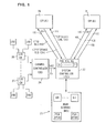
- FIGURE 1 shows a multiprocessor system having two central processors 20 and 21 identified as CP(A) and CP(B), which are connected to a system controller (SC) 22.
- a channel controller (CC) 24 and main storage (MS) 23 also connect to SC22.
- a channel controller (CC) 24 and main storage 23 also connect to SC22.
- a plurality of I/O control units (CUs) 26 through 27 are connected to CC24, and one or more I/O devices (IOD) are connected to each control unit.
- Any I/O device may be started by an instruction executed by either CP(A) or CP(B).
- Any I/O device, its control unit, its sub-channel or channel may generate interrupt signals in the conventional and well known manner.
- I/O type of interrupt signals are sent to channel controller 24 which generates an interrupt command, signal interrupt (SIGI), which communicates each I/O interrupt to SC22 on a connecting bus 25.
- SIGI command has bits which identify the queue in MS23 on which an entry will be posted for this interrupt.
- the SIGI command is generated within CC24 by a processor that executes a microprogram that generates the SIGI signals which are transferred to SC22, and controls the posting of an entry on one of eight queues, QO through Q7, in MS23.
- CC24 enters each new entry at the bottom of the selected queue, and a count field with the queue is updated to indicate the number of active interrupt entries currently in the queue.
- the entries in each queue are address chained in the conventional manner.
- the active entries in each queue represent pending interrupt requests which await handling by either one of the CP(A) 20 or CP(B) 21. As soon as each entry is placed on a queue by CC24, the interrupt signal may be cleared at its source.
- the device causing a queue entry cannot proceed with its next operation until the entry is handled by a selected CP, which will execute a system control program to determine the next operation of the I/O device, CU, subchannel or channel when handling the entry.
- each I/O interrupt queue in MS23 is indicated by a respective position within a pending (PND) register 46.
- Register 46 has eight bit positions 0-7 which correspond to the eight queues QO-Q7 in MS23. Each entry is made on one of queues 0-7 in main storage 23 under control of a microprogram executed in CC24. Each time CC24 makes an entry, it sends a SIGI command to SC22, and the decoded command sets a corresponding bit in PND register 46 to identify the queue on which an entry is to be added.
- Each SIGI command sets its queue respective PND bit in register 46 even though that bit may already be in a set state due to a prior SIGI signal for the same queue, in which case the current SIGI signal only continues the set state of that PND register bit position.
- the SIGI signals from CC24 can only set corresponding bits in the PN D register 46. CC24 cannot reset any bits in register 46. PND register bits can only be reset by CP20 or CP21, when it has handled the last entry on the corresponding queue and thereby emptied the queue. Therefore, the set state of a PND register bit indicates that its queue is non-empty, i.e. contains one or more active entries representing pending I/O interrupts. A reset state for any PND bit indicates its corresponding queue is empty, i.e. does not contain any pending interrupt entry.
- the order of the bit positions 0-7 in PND register 46 represents the respective queues 0-7.
- the queues are given a priority relative to their numerical sequence with queue 0 having the highest priority and queue 7 having the lowest priority.
- Any broadcast bit PND(0)-PND(7) may be masked off by a CP with the conventional I/O mask bits in a control register 51 in the CP. Any PND bit which is masked off is not available for acceptance.
- the eight bit positions in PND register 46 are broadcast as states PND(O) through PND(7) to all CPs, 20 and 21, on PND broadcast busses 11A and 11B.
- Each CP looks at the received state PND(0)- PND (7) on bus llA or 11B, respectively, when the CP is in an interruptable state, during which the CP may accept the highest-priority non-empty queue that is allowed for that CP by its I/O mask in register 51 in FIGURE 3A.
- QID queue identifier
- Each PND bit position broadcasting a zero state is ignored by each CP, because the zero state indicates the corresponding queue is empty.
- Each PND bit position disabled by a CP I/O mask is likewise ignored.
- a CP is interruptable if it is in enabled wait state or reaches an interruptable point in its execution.
- Response busses 12A and 12B are provided from each CP20 and 21 to SC22.
- Each response bus 12 contains six lines which include an accept line, three lines to signal an accept QID, a wait line to signal whether or not the CP is in wait state during the acceptance, and a reset line. If the CP is in enabled wait state at the time of its acceptance of a non-empty queue, the CP signals the SC on its response bus 12 that it is in wait state at the same time it signals its acceptance and the QID. If the CP is not in wait state when it accepts an interrupt request, it only signals on the accept line and the QID lines in its bus 12.
- the acceptance signal and QID remain activated from the time the CP indicates its acceptance until the CP is done operating on the queue, which is when the CP has removed the oldest active entry on the queue. Then, the CP immediately takes the interrupt required by the removed entry, after all signalling between the CP and SC is completed in regard to that entry.
- the wait signal if any, is active for one machine cycle which is during the first cycle for the accept signal.
- a CP may not handle a queue merely because the CP has accepted that queue.
- SC22 selects which CP will handle a queue at any given time by activating a select line 13A or 13B to the selected CP.
- SC selection of CPs is needed because it is possible for more than one CP to simultaneously accept the same queue, but only one CP is permitted to handle any queue at any one time in order to avoid CP conflict in I/O interrupt handling. Therefore, circuitry in SC22 receives the accept, QID and wait (if any) signals from the CPs and always selects only one CP per QID at any one time.
- CPs respond simultaneously with the same QID, only one CP is selected with the following priorities: If one CP signals it is in wait state, the SC selects the CP in wait state. If both CPs are in wait state, the lowest-numbered CP is selected by the SC. If no CP is in wait state, the SC selects the lowest-numbered of the plural responding CPs.
- the SC sends the select signal to the CP on the machine cycle following the first accept cycle.
- the SC inhibits the broadcast of the PND bit for the selected queue to all CPs except the selected CP, so that the selected queue cannot thereafter be selected by any other CP while it is being operated on by the selected CP.
- the broadcast PND states PND(0)-PND(7) may be different from the current set states of the bits in PND register 46.
- each non-selected PND bit continues to be broadcast and therefore remains available for acceptance by another processor.
- acceptance and/or selection can be made by one processor while another processor is handling another queue.
- Plural processors can concurrently be operating on different queues.
- the CP stops sending its accept signal in bus 12A or 12B to the SC.
- the select signal to a CP remains active from the time the CP is selected by the SC until the SC senses that the accept signal has dropped indicating that the CP is done with the selected queue.
- the CP signals the SC on its reset line in bus 12A or 12B if the processor found that no active entry remains in that queue.
- the SC If the accept signal drops without any signal being received on the reset line, the SC is informed that the queue is not empty, and then the SC removes the inhibit on the PND bit for that queue, and this PND bit is again included in the broadcast on bus 11 to all CPs, so that any CP can thereafter accept that queue in order to contend for handling its next entry.
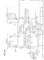
- Bus 25 (Fig. 2) provides each signal interrupt (SIGI) command from the channel controller 24 to a command decoder 19 which provides eight output lines 25-0 through 25-7 that connect to the set inputs for the respective bits in PND register 46.
- Decoder 19 decodes a queue identifier signal sent by the channel controller identifying the queue onto which an entry is to be chained to represent an I/O type of pending interrupt.
- one of the output lines 25-0 through 25-7 will be activated by decoder 19 in response to each SIGI command.
- Shown in detail in FIGURE 2A is an exemplary output line 25-0 which connects to the set input of bit position 0 in interrupt pending (PND) register 46. Not shown to avoid cluttering the drawing is the identical connection of the other seven outputs 25-1 through 25-7 from decoder 19 to the set inputs of the corresponding bit positions 1-7 in P ND register 46.
- the eight output lines from the eight bit positions in PND register 46 are connected through two sets of AND gates 48A-0 through 48A-7, and 48B-0 through 48B-7, respectively to PND busses 11A and 11B to broadcast the states of the PND bit positions to both CP(A) 20 and CP(B) 21.
- the two sets of AND gates 48A and 48B are respectively controlled by bit settings in inhibit registers 43A and 43B.
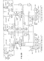
- I/O interrupt acceptance determination circuits in CP(A) (see Fig. 3), which receive broadcast signals from PND bus 11A and provide signals to response bus 12A. Not shown to avoid duplication are the CP(B) circuits identical to those shown for CP(A) except that the CP(B) circuits connect to PND bus 11B, response bus 12B and select line 13B.
- the eight (8) lines of PND bus 11A connect to eight AND gates 53 which also respectively receive eight I/O mask bit states outputted from a control register CR6 (having reference number 51) and the I/O mask bit from bit 6 in PSW register 52.
- I/O interrupt masks in a control register are found in prior commercial IBM System/370 systems.
- the I/O mask controls whether interrupt queue signals on each of the eight lines in PND bus 11A can be passed on to the acceptance-determining circuits in FIGURES 3A.
- PSWs are well known in the art and for example, are used in all commercial IBM System/370 central processing units. Only those PND bus lines which are masked on can transfer respective interrupt signals to an OR circuit 54 and to encoding circuits 70.
- OR circuit 54 provides an any unmasked PND Q output, which indicates whether any queue is non-empty and unmasked.
- the inputs to circuits 70 are outputs 0-6 of the eight enabled PND output lines from AND gates 53, selects the lowest-number enabled PND output line having a one state (representing the highest-priority active queue which is enabled), and encodes the number of the selected PND output line into a three bit code, which is the outputted QID of circuits 70.
- FIGURE 4 shows the details in circuits 70 and is described later herein.
- Gate 81 passes the outputted QID to a queue identifier register 82 which outputs the QID to SC22 on three (3) lines 12A-1, which are part of the CP response bus 12A.
- QID register 82 is set to the value of the lowest-number enabled PND output line having a one state. The QID register will continue to be set to this value until accept trigger 76 becomes active.
- An any enabled request trigger 57 is set during each machine cycle that an output is provided from OR gate 54. Hence, trigger 57 remains set as long as OR gate 54 provides an active output, which remains as long as any unmasked I/O interrupt request is provided to CP(A). Thus, as soon as CP(A) completes handling one I/O interrupt, it may accept another if the request trigger 57 is then set.
- the set output of trigger 57 is provided to an AND gate 58 which also is conditioned by an interruptable state output line 63-1 from a microcode control unit 63, which indicates when CP(A) is in an interruptable state.
- a microcode control unit 63 which indicates when CP(A) is in an interruptable state.
- the CP is in an interruptable state when its microcode control unit 63 reaches and interprets a control word CWk, which occurs when the CP has reached the end of execution of an instruction, is at an interruptable point in a long-execution instruction, or is in wait state and not stopped.
- the take I/O trap output signal from gate 58 indicates that an acceptance-determination operation shall proceed in CP(A) for at least one I/O interrupt request.
- the take I/O trap signal from gate 58 enables an AND gate 59 to pass a microcode control store address from I/O trap address register 56 to unit 63 which accesses control word (CW)1 at the beginning of a microprogram used in the process for making an acceptance determination.
- CW control word
- a compare circuit 71 detects the non-selection of CP(A) when its output changes to an unequal condition before any select signal is received. Compare circuit 71 receives the decoded QID output of register 82 and also receives the eight PND bus lines. The decoded QID will be equal to one active PND signal unless SC22 selects another CP to handle this queue and thereby inhibits the signal for this queue in the broadcasting PND bus 11A, in which case an unequal condition will be provided by compare circuit 71.
- compare circuit 71 will output an equal condition.
- CW2 in unit 63 has its execution initiated by completion of execution of CW1.
- CW2 activates line 63-2 to condition AND gate 72 to output a signal that sets an accept trigger 76.
- accept trigger 76 When accept trigger 76 is set, it outputs an accept signal to SC22 on bus line 12A-2 of the CP response bus 12A.
- gate 81 blocks further updating of the QID register 82 and the response bus 12A contains the value of the current highest priority enabled channel interrupt level along with the accept signal 12A-2.
- Compare circuit 71 monitors the PND bus 11A for the QID number in QID register 82 and AND circuit N3 will set reject trigger 75 if the interrupt level held in the QID register 82 is no longer on the PND bus 11A.
- Reject trigger 75 transfers microcode control to CW6 indicating that the accept request issued by CW2 has been rejected.
- Reject trigger 75 resets accept trigger 76 through OR circuit 87 which in turn allows the QID register 82 to be set to the now current highest priority enabled interrupt.
- Response bus line 12A-3 indicates that a CP is in wait state and able to proceed with processing a pending interrupt.
- AND circuit 77 is conditioned by wait bit 14 in PSW register 52, any enabled interrupt trigger 57, not stopped trigger N, and not already selected by select trigger 55.
- SC22 uses the response bus line 12A-3 for determining selection when simultaneous accept lines 12A-3 and 12B-3 are received.
- the CP selection determination by SC22 is made from the signals it receives on lines 12A-1, 12A-2 and 12A-3 response busses 12A and 12B.
- CP(B) is selected by SC22 to handle a queue which CP(A) is in the process of accepting, or has accepted
- CP(A) will sense its non-selection due to the SC inhibiting of that P ND bit on PND bus 11A at the time that SC22 selects CP(B). That is, this sensing is done by circuit 71 outputting an unequal signal, due to PND bus llA dropping the accepted QID held in QID register 82.
- SC22 activates its CP ( A ) select line 13A, setting select trigger 55 and forces microcode control unit 63 to execute CW3, which causes CP(A) to access the oldest entry on the selected queue in main storage, to decrement by one a number of entry fields of the queue, to store the interrupt code in the CP(A) processor save area (PSA) in main storage 23, and to initiate execution of CW4 if it is the last queue entry or CW5 if the queue is not empty.
- CW4 activates output line 63-4 to provide an empty queue signal and sets a reset latch 88 to provide a reset signal on response bus 12A-4 to the SC.
- the reset in turn turns off accept trigger 76 through OR circuit 87.
- CW5 causes unit 63 to activate output line 63-5 which provides a signal through OR circuit 87 that resets accept trigger 76, which drops the accept signal on line 12A-2 to the SC.
- CW4 or CW5 controls the PSW swapping in CP(A) in the conventional manner which is the interruption operation that initiates the I/O interrupt handling program that handles the pending I/O interrupt represented by the queue entry removed by CW3.
- the acceptance signals are provided to a CP(A) response register 30A (Fig. 2) which is connected to the bus lines 12A-1, 12A-2, 12A-3, and 12A-4.
- the identical register 30B connects to identical lines (not shown) from CP(B).
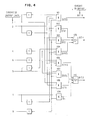
- CP(A) response register 30A and select line 13A is a set of priority circuitry labelled with the letter A and associated with CP(A). Similar circuitry is labelled with the letter B and associated with CP(B) between CP(B) response register 30B and select line 13B. Coordinating priority circuits between the circuits labelled A and B is not labelled with either A or B. The priority circuits associated with CP(A) are described in detail but it is understood that identical circuits are associated with CP(B).
- a decoder 31A is connected to the QID output of register 30A to decode the received QID signal into one of eight signals 0-7 at the output of decoder 31A.
- An OR circuit 32 receives the wait state outputs from both CPs are in wait state, and this output conditions AND gates 36A-0 through 36A-7 (not shown) as well as AND gates 36B-0 through 36B-7 (not shown) to give priority to selection of any CP in wait state over an interruptable CP not in wait state.
- An inverted output of OR circuit 32 indicates a no CP in wait state signal, which conditions AND gates 37A-0 through 37A-7 (not shown) and 37B-0 through 37B-7 (not shown) to control the priority selection among the CPs when no CP is in a wait state. In this case CP(A) is given priority over CP(B).
- the pair of AND gates 33A and 34A together with OR gate 35A develop the accept signal for CP(A). Priority is given to the wait state, if CP(B) is in wait state, then no accept signal can be generated for CP(A) without its wait (WT) bit on in register 30A.
- Common inputs to AND circuits 33A and 34A are the accept (ACPT) bit and inverted reset (RST) bit from register 30A.
- AND circuit 33A examines the wait bit from 30A if the "any CP wait" signal from OR circuit 32 is active, while AND gate 34A develops the accept signal if no CP is waiting.
- the output of the CP(A) accept logic from OR circuit 35A is used in two places. First, it becomes an input to AND gate 36A-0 to develop the "CP(A) accept QO" signal, together with the QO decoded output from circuit 31A and the "no QID select” signal inverted from OR circuit 47-0. Second, it is used to inhibit CP(B) accepting the same QO interrupt. This is done through OR 37A-0, which allows a "CP(B) accept QO" signal from gate 36B-0 only if the CP(A) accept signal is not on or CP(A)'s QID is not decoded as 0 from decoder 31A.
- Each set of AND gates 36A-0 through 36A-7 (not shown) for CP(A) and each queue 0-7 sets a trigger 44A that activates select line 13A to select CP(A) to handle the accepted one of queues 0-7.
- the set of AND gates 36B-0 through 36B-7 sets a trigger 44B that activates select line 13B to select CP(B) to handle its accepted one of queues 0-7.
- any of the AND circuits 36A-0 through 36A-7 or any of the AND gates 36B-0 through 36B-7 turns on a select trigger, it also sets a corresponding bit position within the inhibit register 43A or 43B for the non-selected CP.
- the output of AND circuit 36A-0 is connected to the set input of position 0 in the CP(B) inhibit register 43B as well as to trigger 44A to activate select line 13A to CP(A).
- the inverted output of bit position 0 of register 43B deconditions AND gate 48B-0 which inhibits line 0 in the PND bus 11B to CP(B).
- Identical circuitry not shown exists for each of the other positions in each inhibit register 43A and 43B to control all eight lines in each PND bus 11A and 11B.
- a circuit 47-0 OR's together the position 0 outputs of inhibit registers 43A and 43B.
- the inverted output "no QO select" of 47-0 is used to inhibit the accept AND gates 36A-0 and 36B-0.
- both gates 36A-0 and 36B-0 for the selection of queue 0 are deconditioned, thereby preventing any other CP selection of queue 0 until a reset signal is received ending the current selection of queue 0.
- the other OR circuits 47-1 through 47-7 connected to the other corresponding outputs of inhibit registers 43A and 43B for inhibiting the CP selection of the other queues 1-7 while they are being handled by any CP.
- the C P deactivates its accept signal on line 12A-2 or 12B-2 to response register 30A or 30B for CP(A) or CP(B), respectively.
- the deactivation of the accept signal causes a deactivation of the select signal to that CP and a removal of the inhibit on the PND bus line for that queue.
- This operation is controlled by AND circuits 39A-0 through 39A-7 (not shown) and 39B-0 through 39B-7 (not shown). For example, if queue 0 is being handled by CP(A), AND circuit 39A-0 will become active momentarily when CP(A) drops its accept signal.
- AND circuit 39A-0 is being conditioned by the output of select trigger 44A and by the QID 0 output of decoder 31A when the accept signal drops in register 30A to activate the inverted accept signal input to circuit 39A-0, which activates the output of circuit 39A-0 that passes through OR circuit 42A-0 to reset select trigger 44A-and reset the position 0 in inhibit register 43B.
- the CP Whenever a selected CP completes its handling of the last active entry in a queue, the CP generates a reset signal for a machine cycle on its reset line 12A-4 or 12B-4 to response register 30A or 30B according to which CP did the signalling.
- the reset signal in register 30A or 30B then activates a corresponding AND circuit in group 38A-0 through 38A-7 (not shown) for CP(A) or group 38B-0 through 38B-7 (not shown) for CP(B). For example, if AND gate 38A-0 is activated, it provides an output through OR circuit 45-0 which resets queue position 0 in PND register 46.
- the output of AND circuit 38A-0 also is provided through circuit 42A-0 to reset the select trigger 44A and reset the position 0 of inhibit register 43B.
- Lines 0 to 6 from circuit 53 are used for encoding the most significant queue.
- Code 111 is given for level 7 as well as when there are no enabled pending interrupts. For no enabled interrupts, no action will take place since the any enabled request trigger 57 will not be set.
- the bit 0 output of circuit 70 is provided from AND circuit 101 when it receives any of circuit 53 outputs 4 through 7, or when no circuit 53 output lines are active.
- the bit 1 output of circuit 70 is provided by an OR circuit 105 which is active when any of AND circuits 102, 103 or circuit 104 is active or if no lines are active.
- the bit 2 output of circuit 70 is provided by an OR circuit 110 which is active when any of AND circuits 106, 107, 108 or 109 is active or if no lines are active. Note that AND circuits 101-104 and 106-109 are deactivated by any higher level line which does not produce the same output bit.
Abstract
Description
- This invention relates to multiprocessor systems including I/O interrupt handling mechanisms for receiving plural levels of interrupts from shared input-output (I/O) devices connected to the data processing system for controlling the selection of one of plural processors to handle each I/O interrupt, the selected processor not needing to be the processor which initiated the input-output operation causing the interrupt.
- The prior IBM System/360 Model 67-2 multiprocessor system can select any of its plural processors to handle an I/O interrupt, and the I/O device sending the interrupt signal need not have been started by the processor selected to handle its I/O interrupt signal.
- The System/360 M67-2 multiprocessing system could contain from two to four CPU's and one or two 2946 channel controller units (CCU); each CCU is connected to up to seven I/O channels. Each CCU controls the I/O selection of its connected channels by any CPU issuing a Start I/O (SIO) instruction. The CCU receives each I/O interrupt from its channels, and the CCU selects any available CPU for handling each received I/O interrupt. The CPU selected to handle an I/O interrupt may be different from the CPU which issued the SIO. This is described in the IBM Manual having Form No. Y27-2118-0 which was published in 1967.
- In the System/360 M67-2 MP, any I/O interrupted channel sent a channel interrupt (CI) signal to the CCU. The CI signal was received by the "Interrupt Masking and Interrupt Priority Logic" in the CCU. When one or more channel interrupt signals was received by the CCU, the CI's were filtered by a mask gate matrix, one mask gate for each channel per CPU. The mask gates are enabled/disabled by mask bits in a
control register 4 in each CPU. The CI signals to enabled mask gates are passed to a respective priority circuit for each CPU to permit the simultaneous selection of one CI per CPU. The priority sequence is channels 1-6, 0. When each priority circuit outputs a CI request, it is sent to the respective CPU connected to the priority circuit output. The same CI is normally broadcast to all CPU's. Since up to four CPU's could be configured in a M67-2 MP, a CI request would be broadcast to all (up to four) CPU's simultaneously. - Each M67-2 MP CPU in an interruptable condition normally responds to a CI request with an "Interrupt Response CPUX" signal back to the requesting CCU indicating that the responding CPU can handle the interrupt. (A CPU is interruptable when it is in a wait state or has reached an interruptable point during execution.) The CCU then selected one of the responding CPU's to handle the interrupt. The CCU made the CPU selection by means of its CPU On-line priority logic which gives priority among plural responding CPU's to the lowest numbered CPU, i.e., CPU1 has highest priority and CPU4 has lowest priority. The On-line priority logic outputs the identifier (ID) of the selected CPU.
- The CCU then sends the selected CPU interrupt response signal and the selected CPU ID signal to interrupt response controls in the CCU. They respond by sending to the selected CPU the channel address of the interrupting channel and the unit address of the interrupting device received from the channel. The selected CPU can then take the interrupt by posting the received channel and device addresses, and other received information, into its channel status word (CSW) in main storage and swapping program status words (PSWs).
- If all channels are masked on, only one CI request can be made by a CCU to all CPU's simultaneously. If the channel masks are applied differently by the different CPU's, different CI requests could be made, e.g. a different CI request to each CPU, and each such CPU could simultaneously send an interrupt response signal to the CCU.
- However, in the latter case, only one of simultaneous CPU response signals could be selected by the CCU, because the On-line CPU Priority Logic would select only one CPU at any one time. Each other CPU channel interrupt response remained pending while the CCU selected them, one at a time, in accordance with the On-line CPU priority logic.
- When the On-line logic selects a CPU, the unselected CPUs are not released for handling another CI until the selected CPU is released when it has received the CSW information. Then all CPU responses then existing contend for priority in the CCU, which then determines which CPU will next handle a CI. Hence, no overlap in CSW generation is obtainable among the CPUs. Thus, the system is arranged for the CCU to control plural simultaneous CIs to be serially handled by the plural CPU's.
- After taking the interrupt by storing the CSW and OLD PSW and by accessing the NEW I/O PSW, the interrupted CPU executes the operating system CI handling program. The software may control an interrupted processor to take one or more other interrupts and enqueue them before completing the handling of an interrupt, i.e., nesting the interrupt handling.
- In a U.S.A. patent to Quosig et al 3,421,150 IR's (I/O Interrupt Requests) are queued onto a plurality of lists in main storage. Each IR is put on a list in Main Storage independently of processor selection for handling the IR. Quosig associates the IR lists with different I/O controllers. Quosig sequentially polls his processors in a predetermined priority sequence for determining their interruptability states and selects the first sensed interruptable processor to handle a priority selected IR. Quosig selects the processor in the most interruptable state during the sequential scan.
- An article published in the December 1966 Proceedings of the IEEE on pages 1812 to 1819 by R. J. Gountanis and N. L. Viss is similar in subject matter to the disclosure in U.S.A. patent 3,421,150.
- In a U.S.A. patent to Kurpanek et al 4,015,243 the queuing of each IR is dependent on prior selection of a processor to handle the IR. To sense processor interrupt states, Kurpanek goes to his processors, while Quosig senses processor line signals sent to his multiprocessor interrupt directory hardware.
- On the other hand, the M67-2 MP broadcasts one priority selected IR to all processors in the system. In the M67MP, the processors each determine their acceptance of a broadcast IR, and then the CCU selects an accepting processor and signals the selection to the selected processor. The M67MP processor acceptance signal is "CPU-X Response" to the CCU.
- Kurpanek and Quosig have the interrupt control unit select a candidate processor, and then have that processor (rather than the interrupt control unit) determine the acceptance or rejection of the candidate selection.
- The present invention provides a multiprocessor system including a system controller, plural control processors, at least one input/output processor, shared main storage and an I/O interrupt handling mechanism, communication between elements of the system being via the system controller, the IOP being capable of communicating plural levels of pending I/O interrupt requests each requiring execution of an interrupt handling program by any one of the CPs, characterized in that the I/O interrupt handling mechanism comprises an I/O interrupt pending register forming a logical part of the SC and having a plurality of positions respectively settable by plural levels of I/O IRs from the IOP, each providing an empty/non-empty state signal for a respective queue generated in MS, each queue containing I/O IRs associated with a given I/O IR level, broadcast means connecting the outputs of the positions of the pending register to each of the CPs, accepting means in each CP connected to the broadcast means for accepting a highest-priority-unmasked non-empty state position from the broadcast means as an accepted queue identifier when the CP is in an interruptable state, the accepting means generating and transmitting to the SC an accept signal and an accepted queue identifier signal, selecting means in the SC immediately responsive to all received accept signals and queue identifier signals for selecting one accepting CP and its queue identifier, and the selecting means sending a select signal to each selected CP, and inhibiting means in the SC for inhibiting the broadcast means from transmitting a signal for each pending register position associated with each selected queue identifier to all CPs except the CP selected for the selected queue identifier.
- Embodiments of the invention provide an improvement over the listed prior art in allowing simultaneous control of a plurality of central processors (CPs) for selecting the CPs to process pending channel interrupts (CIs) on a plurality of CI queues in main storage. In one embodiment disclosed hereinafter, a channel processor receives interrupt signals from a plurality of I/O control units, I/O devices, their subchannels and the channel. For each pending interrupt signal it receives, the channel processor posts an interrupt request (IR) entry to one of the queues it selects in accordance with a preassignment of queues to the source and type of interrupt. The channel processor only puts entries on the CI queues but does not process or remove entries from the queues. Queue entries are only removed and processed by selected central processors (CPs) in the multiprocessor system. The CI queues are assigned different priorities in accordance with the speed required for processing the interrupts pending on them. On any single queue, the entries are processed on a first-in, first- out basis by the selected CP, which need not be the CP which issued the start I/O signal resulting in the interrupt.
- Channel interrupt (CI) controller circuits are provided within a system controller (SC) in an MP to determine which CP will be selected to remove and process each pending CI queue entry. Upon the occurrence of an I/O type of interrupt, the channel processor sends an interrupt command to the CI controller indicating which CI queue is to receive an entry for that pending interrupt. As part of this operation, the channel processor posts an IR entry on the selected queue in main storage.
- An interrupt queue pending (PND) register is provided in the CI controller which has register positions respectively assigned to the different CI queues in their priority sequence. The set/reset state of the corresponding positions in the pending register indicate the non-empty/empty condition of the respective CI queues in main storage. Each time the channel processor sends an interrupt command, the CI controller sets the corresponding queue position in the pending register to indicate a non-empty state for that queue.
- The states of all positions of the interrupt queue pending register are broadcast to all CPs in parallel for all queues not having a currently selected CP.
- Whenever any CP is in an interruptable state, it accepts the highest priority unmasked queue signal being broadcast by providing a queue identifier signal and an accept signal to the CI controller in the SC. A CP is in an interruptable state if it is in enabled wait state or has reached an interruptable point in its execution. The accepting CP also sends a wait signal to the CI controller if the CP is then in an enabled wait state.
- CPs simultaneously accepting different queues are not in conflict and are simultaneously selected by the CI controller sending them select signals. The CI controller has a separate select line to each CP on which the controller signals its CP selection. Thus, simultaneous selections can be made for plural queues even though one or more of the queues has plural accepting CPs.
- The CI controller selects among accepting CPs for the same queue by giving priority to any accepting CP in wait state. If more than one CP is in wait state, a preassigned priority by CP number is used to select one of the CPs in wait state. If no CP is in wait state, then the preassigned priority is used to select an accepting CP for that queue.
- Any accepting but non-selected CP immediately senses its non-selection and releases its acceptance. It then accepts any highest priority pending queue. If no pending queue exists, the processor returns to its interrupted operations.
- Upon selection of a CP to process a pending interrupt on an identified queue, the CI controller inhibits the broadcast to other CPS of the non-empty state of the selected queue. Then a second CP cannot accept a queue while it is being processed by a first CP. The states of the non-selected non-empty queues will continue to be broadcast to all CPs so that another queue may at any time be selected by another CP.
- When a selected CP completes its processing of one entry in the accepted queue, the CP turns off its accept signal to the CI controller, which then turns off the select signal to that CP. Also, the inhibit signal is removed on the broadcast of the corresponding queue position of the pending register, so that queue position resumes being broadcast to all CPs if that queue is then non-empty. Then all processors may contend for the next entry on that queue. No contention advantage is provided to the processor which handled the last entry in the same queue, and each entry is selected according to the then current conditions existing among the CPs.
- When a selected CP removes an entry from the queue, the CP updates a queue field in main storage that indicates the number of remaining entries in that queue. If the CP finds there are no further entries in that queue, the CP sends a reset signal on a special line to the CI controller as the CP turns off its accept signal. The reset signal causes the CI controller to reset the corresponding queue position in the pending register in order to broadcast that there are no other pending interrupt entries remaining in that queue at that time.
- After the CP turns off its accept signal, the CP handles its removed entry by interrupting its operation by changing program status words (PSWs) in the conventional manner. The CP then executes an interrupt handling program, after which the CP can accept another I/O interrupt request if any is pending. If no interrupt request exists, the CP returns to normal operation.
- In this way, there is provided for:
- 1. Parallel signalling of plural I/O interrupt pending signals by a CI controller to plural CPs, which may concurrently process plural I/O interrupts in parallel while new I/O interrupts are being signalled to the CI controller.
- 2. An I/O interrupt controller register having a position for each of plural channel interrupt (CI) queues in main storage for interfacing the empty/non-empty states of the respective queues to all central processors (CPs).
- 3. Simultaneously broadcasting to plural CPs, the empty/ non-empty states of the plural CI queues in main storage. A non-empty queue has one or more entries representing a pending interrupt from an I/O device, device controller, subchannel, or channel.
- 4. The simultaneous acceptance by plural CPs for handling the same or different interrupt queues.
- 5. Accept signal lines from each CP to the CI controller to signal the controller of acceptance of an I/O interrupt request by a CP in an interruptable state.
- 6. A CP wait line being provided from each CP to the CI controller to signal the controller that the acceptance of an I/O pending interrupt is by a CP in wait state.
- 7. The CI controller giving selection priority to a CP sending a wait-state acceptance over a CP sending a non-wait-state acceptance, whenever plural CPs simultaneously accept the same queue.
- 8. The CI controller giving selection priority to a highest priority CP of plural CPs simultaneously sending only wait-state acceptances or aonly non-wait-state acceptances.
- 9. CP select lines from the CI controller in parallel to all CPs to enable simultaneous CP selections by the controller.
- 10. CP termination of its accept signal after any selected CP has finished removing a pending interrupt entry from its selected queue.
- 11. Inhibit registers in the CI controller for inhibiting the broadcast of a selected non-empty queue signal to each non-selected CP. The inhibit condition for any queue signal is removed by the CI controller when the selected CP terminates transmission pending interrupt request entry from the queue.
- 12. CP issuance of a reset signal after the selected CP removes the last entry in the selected queue to make the queue empty.
- 13. Any CP being capable of accepting the next entry on a queue upon the completion of handling the prior entry on that queue by any CP.
- 14. Stopping the broadcast of a queue signal to all CPs when a reset signal is provided from any CP handling a last entry on the queue.
- The present invention will be described further by way of example with reference to an embodiment thereof as illustrated in the accompanying drawings in which :-
- FIGURE 1 is a representation of one form of multiprocessing system according to the invention.
- FIGURE 2 (in parts A and B) illustrates the channel interrupt controller located within the SC.
- FIGURE 3 (in parts A and B) illustrates channel interrupt acceptance circuits found in each CP which operates with the channel interrupt controller in the SC.
- FIGURE 4 illustrates a detailed form of "encode-most-significant- queue circuit."
- FIGURE 1 shows a multiprocessor system having two
central processors main storage 23 also connect to SC22. A plurality of I/O control units (CUs) 26 through 27 are connected to CC24, and one or more I/O devices (IOD) are connected to each control unit. Any I/O device may be started by an instruction executed by either CP(A) or CP(B). Any I/O device, its control unit, its sub-channel or channel may generate interrupt signals in the conventional and well known manner. These I/O type of interrupt signals are sent to channelcontroller 24 which generates an interrupt command, signal interrupt (SIGI), which communicates each I/O interrupt to SC22 on a connectingbus 25. The SIGI command has bits which identify the queue in MS23 on which an entry will be posted for this interrupt. The SIGI command is generated within CC24 by a processor that executes a microprogram that generates the SIGI signals which are transferred to SC22, and controls the posting of an entry on one of eight queues, QO through Q7, in MS23. CC24 enters each new entry at the bottom of the selected queue, and a count field with the queue is updated to indicate the number of active interrupt entries currently in the queue. The entries in each queue are address chained in the conventional manner. The active entries in each queue represent pending interrupt requests which await handling by either one of the CP(A) 20 or CP(B) 21. As soon as each entry is placed on a queue by CC24, the interrupt signal may be cleared at its source. - Generally, the device causing a queue entry cannot proceed with its next operation until the entry is handled by a selected CP, which will execute a system control program to determine the next operation of the I/O device, CU, subchannel or channel when handling the entry.
- In SC22, the existence of each I/O interrupt queue in MS23 is indicated by a respective position within a pending (PND)
register 46.Register 46 has eight bit positions 0-7 which correspond to the eight queues QO-Q7 in MS23. Each entry is made on one of queues 0-7 inmain storage 23 under control of a microprogram executed in CC24. Each time CC24 makes an entry, it sends a SIGI command to SC22, and the decoded command sets a corresponding bit in PND register 46 to identify the queue on which an entry is to be added. - Each SIGI command sets its queue respective PND bit in
register 46 even though that bit may already be in a set state due to a prior SIGI signal for the same queue, in which case the current SIGI signal only continues the set state of that PND register bit position. - The SIGI signals from CC24 can only set corresponding bits in the PND register 46. CC24 cannot reset any bits in
register 46. PND register bits can only be reset by CP20 or CP21, when it has handled the last entry on the corresponding queue and thereby emptied the queue. Therefore, the set state of a PND register bit indicates that its queue is non-empty, i.e. contains one or more active entries representing pending I/O interrupts. A reset state for any PND bit indicates its corresponding queue is empty, i.e. does not contain any pending interrupt entry. - The order of the bit positions 0-7 in PND register 46 represents the respective queues 0-7. The queues are given a priority relative to their numerical sequence with
queue 0 having the highest priority andqueue 7 having the lowest priority. - Any broadcast bit PND(0)-PND(7) may be masked off by a CP with the conventional I/O mask bits in a
control register 51 in the CP. Any PND bit which is masked off is not available for acceptance. - The eight bit positions in PND register 46 are broadcast as states PND(O) through PND(7) to all CPs, 20 and 21, on PND broadcast busses 11A and 11B. Each CP looks at the received state PND(0)-PND(7) on bus llA or 11B, respectively, when the CP is in an interruptable state, during which the CP may accept the highest-priority non-empty queue that is allowed for that CP by its I/O mask in
register 51 in FIGURE 3A. Whenever a CP accepts a non-empty queue, it signals its acceptance to SC22 and simultaneously sends the queue identifier (QID) of the accepted queue. Each PND bit position broadcasting a zero state is ignored by each CP, because the zero state indicates the corresponding queue is empty. Each PND bit position disabled by a CP I/O mask is likewise ignored. - A CP is interruptable if it is in enabled wait state or reaches an interruptable point in its execution.
- Response busses 12A and 12B are provided from each CP20 and 21 to SC22. Each response bus 12 contains six lines which include an accept line, three lines to signal an accept QID, a wait line to signal whether or not the CP is in wait state during the acceptance, and a reset line. If the CP is in enabled wait state at the time of its acceptance of a non-empty queue, the CP signals the SC on its response bus 12 that it is in wait state at the same time it signals its acceptance and the QID. If the CP is not in wait state when it accepts an interrupt request, it only signals on the accept line and the QID lines in its bus 12. The acceptance signal and QID remain activated from the time the CP indicates its acceptance until the CP is done operating on the queue, which is when the CP has removed the oldest active entry on the queue. Then, the CP immediately takes the interrupt required by the removed entry, after all signalling between the CP and SC is completed in regard to that entry. The wait signal, if any, is active for one machine cycle which is during the first cycle for the accept signal.
- A CP may not handle a queue merely because the CP has accepted that queue. SC22 selects which CP will handle a queue at any given time by activating a
select line - If only one CP responds, it is selected by the SC. If plural CPs respond simultaneously with different QIDs, they are all selected for their different QIDs.
- If plural CPs respond simultaneously with the same QID, only one CP is selected with the following priorities: If one CP signals it is in wait state, the SC selects the CP in wait state. If both CPs are in wait state, the lowest-numbered CP is selected by the SC. If no CP is in wait state, the SC selects the lowest-numbered of the plural responding CPs.
- The SC sends the select signal to the CP on the machine cycle following the first accept cycle. During the select cycle, the SC inhibits the broadcast of the PND bit for the selected queue to all CPs except the selected CP, so that the selected queue cannot thereafter be selected by any other CP while it is being operated on by the selected CP. Thus, the broadcast PND states PND(0)-PND(7) may be different from the current set states of the bits in
PND register 46. - Although the broadcast of a selected PND bit is inhibited to each other CP, none of the non-selected PND bits is inhibited; and each non-selected PND bit continues to be broadcast and therefore remains available for acceptance by another processor. Thus, acceptance and/or selection can be made by one processor while another processor is handling another queue. Plural processors can concurrently be operating on different queues.
- When a selected CP has completed its operation on its selected queue, the CP stops sending its accept signal in
bus 12A or 12B to the SC. The select signal to a CP remains active from the time the CP is selected by the SC until the SC senses that the accept signal has dropped indicating that the CP is done with the selected queue. - During the last machine cycle of the CP accept signal, the CP signals the SC on its reset line in
bus 12A or 12B if the processor found that no active entry remains in that queue. - If the accept signal drops without any signal being received on the reset line, the SC is informed that the queue is not empty, and then the SC removes the inhibit on the PND bit for that queue, and this PND bit is again included in the broadcast on bus 11 to all CPs, so that any CP can thereafter accept that queue in order to contend for handling its next entry.
- However, if a CP sends a signal on its reset line during the last accept signal, the SC knows that the queue is now empty, and the SC resets the corresponding queue bit in PND register 46 while removing the inhibit on that bit to PND bus 11. Thus, that PND bit will no longer be broadcast because it is in reset state in
register 46 due to its queue now being empty. But as soon as CC24 again provides a SIGI command for that queue, its PND bit is again set and broadcast to all CPs. - Bus 25 (Fig. 2) provides each signal interrupt (SIGI) command from the
channel controller 24 to acommand decoder 19 which provides eight output lines 25-0 through 25-7 that connect to the set inputs for the respective bits inPND register 46.Decoder 19 decodes a queue identifier signal sent by the channel controller identifying the queue onto which an entry is to be chained to represent an I/O type of pending interrupt. Thus, one of the output lines 25-0 through 25-7 will be activated bydecoder 19 in response to each SIGI command. Shown in detail in FIGURE 2A is an exemplary output line 25-0 which connects to the set input ofbit position 0 in interrupt pending (PND)register 46. Not shown to avoid cluttering the drawing is the identical connection of the other seven outputs 25-1 through 25-7 fromdecoder 19 to the set inputs of the corresponding bit positions 1-7 in PND register 46. - The eight output lines from the eight bit positions in PND register 46 are connected through two sets of AND
gates 48A-0 through 48A-7, and 48B-0 through 48B-7, respectively toPND busses 11A and 11B to broadcast the states of the PND bit positions to both CP(A) 20 and CP(B) 21. The two sets of ANDgates 48A and 48B are respectively controlled by bit settings in inhibitregisters - I/O interrupt acceptance determination circuits in CP(A) (see Fig. 3), which receive broadcast signals from
PND bus 11A and provide signals toresponse bus 12A. Not shown to avoid duplication are the CP(B) circuits identical to those shown for CP(A) except that the CP(B) circuits connect to PND bus 11B, response bus 12B andselect line 13B. - The eight (8) lines of
PND bus 11A connect to eight ANDgates 53 which also respectively receive eight I/O mask bit states outputted from a control register CR6 (having reference number 51) and the I/O mask bit frombit 6 inPSW register 52. - I/O interrupt masks in a control register are found in prior commercial IBM System/370 systems. The I/O mask controls whether interrupt queue signals on each of the eight lines in
PND bus 11A can be passed on to the acceptance-determining circuits in FIGURES 3A. PSWs are well known in the art and for example, are used in all commercial IBM System/370 central processing units. Only those PND bus lines which are masked on can transfer respective interrupt signals to anOR circuit 54 and to encodingcircuits 70. - OR
circuit 54 provides an any unmasked PND Q output, which indicates whether any queue is non-empty and unmasked. - The inputs to
circuits 70 are outputs 0-6 of the eight enabled PND output lines from ANDgates 53, selects the lowest-number enabled PND output line having a one state (representing the highest-priority active queue which is enabled), and encodes the number of the selected PND output line into a three bit code, which is the outputted QID ofcircuits 70. FIGURE 4 shows the details incircuits 70 and is described later herein. -
Gate 81 passes the outputted QID to aqueue identifier register 82 which outputs the QID to SC22 on three (3)lines 12A-1, which are part of theCP response bus 12A. Hence, QID register 82 is set to the value of the lowest-number enabled PND output line having a one state. The QID register will continue to be set to this value until accepttrigger 76 becomes active. - An any enabled
request trigger 57 is set during each machine cycle that an output is provided fromOR gate 54. Hence, trigger 57 remains set as long as ORgate 54 provides an active output, which remains as long as any unmasked I/O interrupt request is provided to CP(A). Thus, as soon as CP(A) completes handling one I/O interrupt, it may accept another if therequest trigger 57 is then set. - The set output of
trigger 57 is provided to an ANDgate 58 which also is conditioned by an interruptable state output line 63-1 from a microcode control unit 63, which indicates when CP(A) is in an interruptable state. Normally, the CP is in an interruptable state when its microcode control unit 63 reaches and interprets a control word CWk, which occurs when the CP has reached the end of execution of an instruction, is at an interruptable point in a long-execution instruction, or is in wait state and not stopped. - The take I/O trap output signal from
gate 58 indicates that an acceptance-determination operation shall proceed in CP(A) for at least one I/O interrupt request. The take I/O trap signal fromgate 58 enables an ANDgate 59 to pass a microcode control store address from I/Otrap address register 56 to unit 63 which accesses control word (CW)1 at the beginning of a microprogram used in the process for making an acceptance determination. - A possibility exists that CP(A) will not be selected by SC22 when CP(A) is about to accept an I/O interrupt request. A compare
circuit 71 detects the non-selection of CP(A) when its output changes to an unequal condition before any select signal is received. Comparecircuit 71 receives the decoded QID output ofregister 82 and also receives the eight PND bus lines. The decoded QID will be equal to one active PND signal unless SC22 selects another CP to handle this queue and thereby inhibits the signal for this queue in thebroadcasting PND bus 11A, in which case an unequal condition will be provided by comparecircuit 71. - Therefore, as long as SC22 has not selected any CP to handle the QID in
register 82, comparecircuit 71 will output an equal condition. CW2 in unit 63 has its execution initiated by completion of execution of CW1. CW2 activates line 63-2 to condition ANDgate 72 to output a signal that sets an accepttrigger 76. When accepttrigger 76 is set, it outputs an accept signal to SC22 onbus line 12A-2 of theCP response bus 12A. - When CW2 activates line 63-2, one and only one of two actions take place depending on the current state of the any
enabled request trigger 57. If the anyenabled request trigger 57 is on, the accepttrigger 76 is set. If the anyenabled request trigger 57 is off, thereject trigger 75 is set via AND circuit N2. - When the accept
trigger 76 is on,gate 81 blocks further updating of theQID register 82 and theresponse bus 12A contains the value of the current highest priority enabled channel interrupt level along with the acceptsignal 12A-2. - Compare
circuit 71 monitors thePND bus 11A for the QID number inQID register 82 and AND circuit N3 will setreject trigger 75 if the interrupt level held in theQID register 82 is no longer on thePND bus 11A. Rejecttrigger 75 transfers microcode control to CW6 indicating that the accept request issued by CW2 has been rejected. Rejecttrigger 75 resets accepttrigger 76 through ORcircuit 87 which in turn allows theQID register 82 to be set to the now current highest priority enabled interrupt. -
Response bus line 12A-3 indicates that a CP is in wait state and able to proceed with processing a pending interrupt. ANDcircuit 77 is conditioned bywait bit 14 inPSW register 52, any enabled interrupttrigger 57, not stopped trigger N, and not already selected byselect trigger 55. SC22 uses theresponse bus line 12A-3 for determining selection when simultaneous acceptlines 12A-3 and 12B-3 are received. - The CP selection determination by SC22 is made from the signals it receives on
lines 12A-1, 12A-2 and 12A-3response busses 12A and 12B. Thus, if CP(B) is selected by SC22 to handle a queue which CP(A) is in the process of accepting, or has accepted, then CP(A) will sense its non-selection due to the SC inhibiting of that PND bit onPND bus 11A at the time that SC22 selects CP(B). That is, this sensing is done bycircuit 71 outputting an unequal signal, due to PND bus llA dropping the accepted QID held inQID register 82. - If CP(A) is selected, SC22 activates its CP(A)
select line 13A, settingselect trigger 55 and forces microcode control unit 63 to execute CW3, which causes CP(A) to access the oldest entry on the selected queue in main storage, to decrement by one a number of entry fields of the queue, to store the interrupt code in the CP(A) processor save area (PSA) inmain storage 23, and to initiate execution of CW4 if it is the last queue entry or CW5 if the queue is not empty. - CW4 activates output line 63-4 to provide an empty queue signal and sets a
reset latch 88 to provide a reset signal onresponse bus 12A-4 to the SC. The reset in turn turns off accepttrigger 76 through ORcircuit 87. CW5 causes unit 63 to activate output line 63-5 which provides a signal through ORcircuit 87 that resets accepttrigger 76, which drops the accept signal online 12A-2 to the SC. Then, CW4 or CW5 controls the PSW swapping in CP(A) in the conventional manner which is the interruption operation that initiates the I/O interrupt handling program that handles the pending I/O interrupt represented by the queue entry removed by CW3. - The acceptance signals are provided to a CP(A) response register 30A (Fig. 2) which is connected to the
bus lines 12A-1, 12A-2, 12A-3, and 12A-4. Theidentical register 30B connects to identical lines (not shown) from CP(B). - Between CP(A)
response register 30A andselect line 13A is a set of priority circuitry labelled with the letter A and associated with CP(A). Similar circuitry is labelled with the letter B and associated with CP(B) between CP(B)response register 30B andselect line 13B. Coordinating priority circuits between the circuits labelled A and B is not labelled with either A or B. The priority circuits associated with CP(A) are described in detail but it is understood that identical circuits are associated with CP(B). - A
decoder 31A is connected to the QID output ofregister 30A to decode the received QID signal into one of eight signals 0-7 at the output ofdecoder 31A. - An OR
circuit 32 receives the wait state outputs from both CPs are in wait state, and this output conditions ANDgates 36A-0 through 36A-7 (not shown) as well as ANDgates 36B-0 through 36B-7 (not shown) to give priority to selection of any CP in wait state over an interruptable CP not in wait state. - An inverted output of OR
circuit 32 indicates a no CP in wait state signal, which conditions ANDgates 37A-0 through 37A-7 (not shown) and 37B-0 through 37B-7 (not shown) to control the priority selection among the CPs when no CP is in a wait state. In this case CP(A) is given priority over CP(B). - The pair of AND
gates 33A and 34A together withOR gate 35A develop the accept signal for CP(A). Priority is given to the wait state, if CP(B) is in wait state, then no accept signal can be generated for CP(A) without its wait (WT) bit on inregister 30A. Common inputs to ANDcircuits 33A and 34A are the accept (ACPT) bit and inverted reset (RST) bit fromregister 30A. ANDcircuit 33A examines the wait bit from 30A if the "any CP wait" signal fromOR circuit 32 is active, while AND gate 34A develops the accept signal if no CP is waiting. - The output of the CP(A) accept logic from OR
circuit 35A is used in two places. First, it becomes an input to ANDgate 36A-0 to develop the "CP(A) accept QO" signal, together with the QO decoded output fromcircuit 31A and the "no QID select" signal inverted from OR circuit 47-0. Second, it is used to inhibit CP(B) accepting the same QO interrupt. This is done throughOR 37A-0, which allows a "CP(B) accept QO" signal fromgate 36B-0 only if the CP(A) accept signal is not on or CP(A)'s QID is not decoded as 0 fromdecoder 31A. - Each set of AND
gates 36A-0 through 36A-7 (not shown) for CP(A) and each queue 0-7 sets a trigger 44A that activatesselect line 13A to select CP(A) to handle the accepted one of queues 0-7. Similarly, the set of ANDgates 36B-0 through 36B-7 sets atrigger 44B that activatesselect line 13B to select CP(B) to handle its accepted one of queues 0-7. - At the same time that any of the AND
circuits 36A-0 through 36A-7 or any of the ANDgates 36B-0 through 36B-7 turns on a select trigger, it also sets a corresponding bit position within the inhibitregister circuit 36A-0 is connected to the set input ofposition 0 in the CP(B) inhibitregister 43B as well as to trigger 44A to activateselect line 13A to CP(A). The inverted output ofbit position 0 ofregister 43B deconditions AND gate 48B-0 which inhibitsline 0 in the PND bus 11B to CP(B). Identical circuitry not shown exists for each of the other positions in each inhibitregister PND bus 11A and 11B. - A circuit 47-0 OR's together the
position 0 outputs of inhibitregisters gates 36A-0 and 36B-0. Thus, ifqueue 0 is selected by any CP, bothgates 36A-0 and 36B-0 for the selection ofqueue 0 are deconditioned, thereby preventing any other CP selection ofqueue 0 until a reset signal is received ending the current selection ofqueue 0. Likewise, not shown are the other OR circuits 47-1 through 47-7 connected to the other corresponding outputs of inhibitregisters - Whenever a selected CP is done handling an entry in a queue, the CP deactivates its accept signal on
line 12A-2 or 12B-2 to response register 30A or 30B for CP(A) or CP(B), respectively. The deactivation of the accept signal causes a deactivation of the select signal to that CP and a removal of the inhibit on the PND bus line for that queue. This operation is controlled by ANDcircuits 39A-0 through 39A-7 (not shown) and 39B-0 through 39B-7 (not shown). For example, ifqueue 0 is being handled by CP(A), ANDcircuit 39A-0 will become active momentarily when CP(A) drops its accept signal. That is, ANDcircuit 39A-0 is being conditioned by the output of select trigger 44A and by theQID 0 output ofdecoder 31A when the accept signal drops inregister 30A to activate the inverted accept signal input tocircuit 39A-0, which activates the output ofcircuit 39A-0 that passes through ORcircuit 42A-0 to reset select trigger 44A-and reset theposition 0 in inhibitregister 43B. - Whenever a selected CP completes its handling of the last active entry in a queue, the CP generates a reset signal for a machine cycle on its
reset line 12A-4 or 12B-4 to response register 30A or 30B according to which CP did the signalling. The reset signal inregister group 38A-0 through 38A-7 (not shown) for CP(A) or group 38B-0 through 38B-7 (not shown) for CP(B). For example, if ANDgate 38A-0 is activated, it provides an output through OR circuit 45-0 which resetsqueue position 0 inPND register 46. The output of ANDcircuit 38A-0 also is provided throughcircuit 42A-0 to reset the select trigger 44A and reset theposition 0 of inhibitregister 43B.Lines 0 to 6 fromcircuit 53 are used for encoding the most significant queue. Code 111 is given forlevel 7 as well as when there are no enabled pending interrupts. For no enabled interrupts, no action will take place since the anyenabled request trigger 57 will not be set. - The complement output of all
circuit 53 lines are used, but the true output oflines bit 0 output ofcircuit 70 is provided from ANDcircuit 101 when it receives any ofcircuit 53outputs 4 through 7, or when nocircuit 53 output lines are active. Thebit 1 output ofcircuit 70 is provided by an ORcircuit 105 which is active when any of ANDcircuits circuit 104 is active or if no lines are active. Thebit 2 output ofcircuit 70 is provided by an ORcircuit 110 which is active when any of ANDcircuits - The operation of the circuits in FIGURES 2 and 3 can be summarized by the following flow charts:


- Although a multiprocessor with two CPs and one SC has been described in the detailed embodiment, it is apparent to those skilled in the computer science arts that the concepts taught herein can easily be extended to a multiprocessor with more than two CPs and more than one SC, wherein the CI controller in each SC resolves contentions among all CPs for each queue.
Claims (21)
Applications Claiming Priority (2)
| Application Number | Priority Date | Filing Date | Title |
|---|---|---|---|
| US91902 | 1979-11-06 | ||
| US06/091,902 US4271468A (en) | 1979-11-06 | 1979-11-06 | Multiprocessor mechanism for handling channel interrupts |
Publications (2)
| Publication Number | Publication Date |
|---|---|
| EP0028335A1 true EP0028335A1 (en) | 1981-05-13 |
| EP0028335B1 EP0028335B1 (en) | 1984-02-22 |
Family
ID=22230224
Family Applications (1)
| Application Number | Title | Priority Date | Filing Date |
|---|---|---|---|
| EP80106268A Expired EP0028335B1 (en) | 1979-11-06 | 1980-10-15 | Multiprocessor system including i/o interrupt handling mechanism |
Country Status (5)
| Country | Link |
|---|---|
| US (1) | US4271468A (en) |
| EP (1) | EP0028335B1 (en) |
| JP (1) | JPS5820059B2 (en) |
| CA (1) | CA1143852A (en) |
| DE (1) | DE3066708D1 (en) |
Cited By (2)
| Publication number | Priority date | Publication date | Assignee | Title |
|---|---|---|---|---|
| EP0192956A1 (en) * | 1985-02-28 | 1986-09-03 | International Business Machines Corporation | Interrupt handler for a digital processing system |
| US4858108A (en) * | 1985-03-20 | 1989-08-15 | Hitachi, Ltd. | Priority control architecture for input/output operation |
Families Citing this family (90)
| Publication number | Priority date | Publication date | Assignee | Title |
|---|---|---|---|---|
| US4386400A (en) * | 1977-12-15 | 1983-05-31 | International Business Machines Corp. | Reset of a selected I/O channel and associated peripheral equipment by means independent of the channel |
| FR2472234A1 (en) * | 1979-12-21 | 1981-06-26 | Philips Ind Commerciale | COMMUNICATION PROTOCOLS MANAGED BY COMMUNICATION MODULES USED IN A DISTRIBUTED DATA PROCESSING SYSTEM |
| US4425615A (en) | 1980-11-14 | 1984-01-10 | Sperry Corporation | Hierarchical memory system having cache/disk subsystem with command queues for plural disks |
| US4476524A (en) * | 1981-07-02 | 1984-10-09 | International Business Machines Corporation | Page storage control methods and means |
| US4482949A (en) * | 1981-07-20 | 1984-11-13 | Motorola, Inc. | Unit for prioritizing earlier and later arriving input requests |
| US4965825A (en) * | 1981-11-03 | 1990-10-23 | The Personalized Mass Media Corporation | Signal processing apparatus and methods |
| US4604500A (en) * | 1981-12-02 | 1986-08-05 | At&T Bell Laboratories | Multiprocessing interrupt arrangement |
| JPS58222364A (en) * | 1982-06-18 | 1983-12-24 | Fujitsu Ltd | Access control system of disc device in terminal system |
| US4495569A (en) * | 1982-06-28 | 1985-01-22 | Mitsubishi Denki Kabushiki Kaisha | Interrupt control for multiprocessor system with storage data controlling processor interrupted by devices |
| DE3236812A1 (en) * | 1982-10-05 | 1984-04-05 | Standard Elektrik Lorenz Ag, 7000 Stuttgart | REMOTE CONTROL SYSTEM |
| US4482956A (en) * | 1982-11-04 | 1984-11-13 | International Business Machines Corporation | Parallel queueing method |
| US4703419A (en) * | 1982-11-26 | 1987-10-27 | Zenith Electronics Corporation | Switchcover means and method for dual mode microprocessor system |
| JPS5999521A (en) * | 1982-11-29 | 1984-06-08 | Toshiba Corp | Interface circuit |
| JPH077379B2 (en) * | 1983-06-22 | 1995-01-30 | 株式会社日立製作所 | Interrupt selection method for multi-processing system |
| US4618968A (en) * | 1983-11-04 | 1986-10-21 | Motorola, Inc. | Output compare system and method automatically controlilng multiple outputs in a data processor |
| US4604694A (en) * | 1983-12-14 | 1986-08-05 | International Business Machines Corporation | Shared and exclusive access control |
| US4980820A (en) * | 1985-02-28 | 1990-12-25 | International Business Machines Corporation | Interrupt driven prioritized queue |
| US4779195A (en) * | 1985-06-28 | 1988-10-18 | Hewlett-Packard Company | Interrupt system using masking register in processor for selectively establishing device eligibility to interrupt a particular processor |
| JPH07104841B2 (en) * | 1986-07-24 | 1995-11-13 | 株式会社日立製作所 | Interrupt control method for multiprocessing system |
| JPH0679305B2 (en) * | 1987-05-01 | 1994-10-05 | ディジタル イクイプメント コーポレーション | Device and method for responding to an interrupt using a hold bus |
| US4953072A (en) * | 1987-05-01 | 1990-08-28 | Digital Equipment Corporation | Node for servicing interrupt request messages on a pended bus |
| WO1988008575A1 (en) * | 1987-05-01 | 1988-11-03 | Digital Equipment Corporation | Interrupting node for providing interrupt requests to a pended bus |
| US5148544A (en) * | 1987-07-01 | 1992-09-15 | Digital Equipment Corporation | Apparatus and method for control of asynchronous program interrupt events in a data processing system |
| US4843541A (en) * | 1987-07-29 | 1989-06-27 | International Business Machines Corporation | Logical resource partitioning of a data processing system |
| US4965716A (en) * | 1988-03-11 | 1990-10-23 | International Business Machines Corporation | Fast access priority queue for managing multiple messages at a communications node or managing multiple programs in a multiprogrammed data processor |
| US4959781A (en) * | 1988-05-16 | 1990-09-25 | Stardent Computer, Inc. | System for assigning interrupts to least busy processor that already loaded same class of interrupt routines |
| JPH07104842B2 (en) * | 1989-03-03 | 1995-11-13 | 日本電気株式会社 | External storage interrupt control method |
| US5131081A (en) * | 1989-03-23 | 1992-07-14 | North American Philips Corp., Signetics Div. | System having a host independent input/output processor for controlling data transfer between a memory and a plurality of i/o controllers |
| US5247685A (en) * | 1989-11-03 | 1993-09-21 | Compaq Computer Corp. | Interrupt handling in an asymmetric multiprocessor computer system |
| US5325536A (en) * | 1989-12-07 | 1994-06-28 | Motorola, Inc. | Linking microprocessor interrupts arranged by processing requirements into separate queues into one interrupt processing routine for execution as one routine |
| JPH03210649A (en) * | 1990-01-12 | 1991-09-13 | Fujitsu Ltd | Microcomputer and its bus cycle control method |
| KR940001878B1 (en) * | 1990-03-08 | 1994-03-10 | 가부시끼가이샤 히다찌세이사꾸쇼 | Multiprocessor system and apparatus for interrupt control thereof |
| JPH07104833B2 (en) * | 1990-03-09 | 1995-11-13 | 富士通株式会社 | Multiprocessor system |
| KR950008837B1 (en) * | 1990-03-09 | 1995-08-08 | 후지쓰 가부시끼가이샤 | Control system for multiprocessor system |
| JPH0474229A (en) * | 1990-07-17 | 1992-03-09 | Toshiba Corp | Information processor |
| US5287523A (en) * | 1990-10-09 | 1994-02-15 | Motorola, Inc. | Method for servicing a peripheral interrupt request in a microcontroller |
| KR950014373B1 (en) * | 1990-11-02 | 1995-11-25 | 니뽄 덴끼 가부시끼 가이샤 | Interrupt controller |
| JP2855298B2 (en) * | 1990-12-21 | 1999-02-10 | インテル・コーポレーション | Arbitration method of interrupt request and multiprocessor system |
| US5613128A (en) * | 1990-12-21 | 1997-03-18 | Intel Corporation | Programmable multi-processor interrupt controller system with a processor integrated local interrupt controller |
| US5555420A (en) * | 1990-12-21 | 1996-09-10 | Intel Corporation | Multiprocessor programmable interrupt controller system with separate interrupt bus and bus retry management |
| JP2770603B2 (en) * | 1991-03-14 | 1998-07-02 | 三菱電機株式会社 | Parallel computer |
| JP2625589B2 (en) * | 1991-04-22 | 1997-07-02 | インターナショナル・ビジネス・マシーンズ・コーポレイション | Multiprocessor system |
| EP0535821B1 (en) * | 1991-09-27 | 1997-11-26 | Sun Microsystems, Inc. | Method and apparatus for dynamically steering undirected interrupts |
| JP2566717B2 (en) * | 1992-03-30 | 1996-12-25 | インターナショナル・ビジネス・マシーンズ・コーポレイション | Conditional operation providing apparatus and method |
| US5581770A (en) * | 1992-06-04 | 1996-12-03 | Mitsubishi Denki Kabushiki Kaisha | Floating interruption handling system and method |
| US5438677A (en) * | 1992-08-17 | 1995-08-01 | Intel Corporation | Mutual exclusion for computer system |
| US5517624A (en) * | 1992-10-02 | 1996-05-14 | Compaq Computer Corporation | Multiplexed communication protocol between central and distributed peripherals in multiprocessor computer systems |
| EP0602858A1 (en) * | 1992-12-18 | 1994-06-22 | International Business Machines Corporation | Apparatus and method for servicing interrupts in a multiprocessor system |
| GB2277816B (en) * | 1993-05-04 | 1997-09-03 | Motorola Inc | Data communication system |
| US5381541A (en) * | 1993-05-26 | 1995-01-10 | International Business Machines Corp. | Computer system having planar board with single interrupt controller and processor card with plural processors and interrupt director |
| CA2123447C (en) * | 1993-09-20 | 1999-02-16 | Richard L. Arndt | Scalable system interrupt structure for a multiprocessing system |
| SG67906A1 (en) * | 1993-12-16 | 1999-10-19 | Intel Corp | Multiple programmable interrupt controllers in a multi-processor system |
| US5613126A (en) * | 1994-05-31 | 1997-03-18 | Advanced Micro Devices, Inc. | Timer tick auto-chaining technique within a symmetrical multiprocessing system |
| CA2154509A1 (en) * | 1994-10-03 | 1996-04-04 | Paul Peixoto Carreiro | Method and apparatus for automatic frame transmission on a channel to controller interface in a data processing system |
| US5560018A (en) * | 1994-12-16 | 1996-09-24 | International Business Machines Corporation | Providing external interrupt serialization compatibility in a multiprocessing environment for software written to run in a uniprocessor environment |
| US5872982A (en) * | 1994-12-28 | 1999-02-16 | Compaq Computer Corporation | Reducing the elapsed time period between an interrupt acknowledge and an interrupt vector |
| US5737547A (en) * | 1995-06-07 | 1998-04-07 | Microunity Systems Engineering, Inc. | System for placing entries of an outstanding processor request into a free pool after the request is accepted by a corresponding peripheral device |
| FR2737590B1 (en) * | 1995-08-03 | 1997-10-17 | Sgs Thomson Microelectronics | INTERRUPTION MANAGEMENT DEVICE |
| US5606703A (en) * | 1995-12-06 | 1997-02-25 | International Business Machines Corporation | Interrupt protocol system and method using priority-arranged queues of interrupt status block control data structures |
| US5850555A (en) * | 1995-12-19 | 1998-12-15 | Advanced Micro Devices, Inc. | System and method for validating interrupts before presentation to a CPU |
| US5894578A (en) * | 1995-12-19 | 1999-04-13 | Advanced Micro Devices, Inc. | System and method for using random access memory in a programmable interrupt controller |
| US5850558A (en) * | 1995-12-19 | 1998-12-15 | Advanced Micro Devices | System and method for referencing interrupt request information in a programmable interrupt controller |
| US5778236A (en) * | 1996-05-17 | 1998-07-07 | Advanced Micro Devices, Inc. | Multiprocessing interrupt controller on I/O bus |
| US6065088A (en) * | 1998-08-31 | 2000-05-16 | International Business Machines Corporation | System and method for interrupt command queuing and ordering |
| US6816934B2 (en) | 2000-12-22 | 2004-11-09 | Hewlett-Packard Development Company, L.P. | Computer system with registered peripheral component interconnect device for processing extended commands and attributes according to a registered peripheral component interconnect protocol |
| US7013305B2 (en) | 2001-10-01 | 2006-03-14 | International Business Machines Corporation | Managing the state of coupling facility structures, detecting by one or more systems coupled to the coupling facility, the suspended state of the duplexed command, detecting being independent of message exchange |
| US6701429B1 (en) | 1998-12-03 | 2004-03-02 | Telefonaktiebolaget Lm Ericsson(Publ) | System and method of start-up in efficient way for multi-processor systems based on returned identification information read from pre-determined memory location |
| US6345325B1 (en) * | 1999-02-19 | 2002-02-05 | International Business Machines Corporation | Method and apparatus for ensuring accurate and timely processing of data using a queued direct input-output device |
| US6345326B1 (en) * | 1999-02-19 | 2002-02-05 | International Business Machines Corporation | Computer program device and product for timely processing of data using a queued direct input-output device |
| US6986137B1 (en) * | 1999-09-28 | 2006-01-10 | International Business Machines Corporation | Method, system and program products for managing logical processors of a computing environment |
| US6651125B2 (en) * | 1999-09-28 | 2003-11-18 | International Business Machines Corporation | Processing channel subsystem pending I/O work queues based on priorities |
| US6937611B1 (en) * | 2000-04-21 | 2005-08-30 | Sun Microsystems, Inc. | Mechanism for efficient scheduling of communication flows |
| US7478185B2 (en) * | 2007-01-05 | 2009-01-13 | International Business Machines Corporation | Directly initiating by external adapters the setting of interruption initiatives |
| US7752370B2 (en) * | 2007-04-12 | 2010-07-06 | International Business Machines Corporation | Splitting one hardware interrupt to multiple handlers |
| US8478922B2 (en) | 2010-06-23 | 2013-07-02 | International Business Machines Corporation | Controlling a rate at which adapter interruption requests are processed |
| US9342352B2 (en) | 2010-06-23 | 2016-05-17 | International Business Machines Corporation | Guest access to address spaces of adapter |
| US8468284B2 (en) | 2010-06-23 | 2013-06-18 | International Business Machines Corporation | Converting a message signaled interruption into an I/O adapter event notification to a guest operating system |
| US8572635B2 (en) | 2010-06-23 | 2013-10-29 | International Business Machines Corporation | Converting a message signaled interruption into an I/O adapter event notification |
| US8621112B2 (en) | 2010-06-23 | 2013-12-31 | International Business Machines Corporation | Discovery by operating system of information relating to adapter functions accessible to the operating system |
| US8615645B2 (en) | 2010-06-23 | 2013-12-24 | International Business Machines Corporation | Controlling the selectively setting of operational parameters for an adapter |
| US8504754B2 (en) * | 2010-06-23 | 2013-08-06 | International Business Machines Corporation | Identification of types of sources of adapter interruptions |
| US9213661B2 (en) | 2010-06-23 | 2015-12-15 | International Business Machines Corporation | Enable/disable adapters of a computing environment |
| US8626970B2 (en) | 2010-06-23 | 2014-01-07 | International Business Machines Corporation | Controlling access by a configuration to an adapter function |
| US8850450B2 (en) | 2012-01-18 | 2014-09-30 | International Business Machines Corporation | Warning track interruption facility |
| US9104508B2 (en) | 2012-01-18 | 2015-08-11 | International Business Machines Corporation | Providing by one program to another program access to a warning track facility |
| US9110878B2 (en) * | 2012-01-18 | 2015-08-18 | International Business Machines Corporation | Use of a warning track interruption facility by a program |
| US8868810B2 (en) * | 2012-04-12 | 2014-10-21 | International Business Machines Corporation | Managing over-initiative thin interrupts |
| GB201405323D0 (en) | 2014-03-25 | 2014-05-07 | Imagination Tech Ltd | Prioritsing events to which a processor is to respond |
| US10310923B1 (en) | 2014-08-28 | 2019-06-04 | Seagate Technology Llc | Probabilistic aging command sorting |
| US10831403B2 (en) | 2017-05-19 | 2020-11-10 | Seagate Technology Llc | Probabalistic command aging and selection |
Citations (7)
| Publication number | Priority date | Publication date | Assignee | Title |
|---|---|---|---|---|
| US3421150A (en) * | 1966-08-26 | 1969-01-07 | Sperry Rand Corp | Multiprocessor interrupt directory |
| US4015243A (en) * | 1975-06-02 | 1977-03-29 | Kurpanek Horst G | Multi-processing computer system |
| US4096564A (en) * | 1973-01-12 | 1978-06-20 | Hitachi, Ltd. | Data processing system with interrupt functions |
| DE2847216A1 (en) * | 1977-10-28 | 1979-05-03 | Hitachi Ltd | DATA PROCESSING SYSTEM WITH MULTIPROGRAM OPERATION |
| DE2856768A1 (en) * | 1977-12-30 | 1979-07-05 | Rca Corp | PRIORITY VECTOR INTERRUPTION WITH A DEVICE FOR THE DIRECT PRODUCTION OF AN ADDRESS BRANCH |
| DE2902465A1 (en) * | 1978-01-23 | 1979-07-26 | Data General Corp | DATA PROCESSING ARRANGEMENT |
| DE2841041A1 (en) * | 1977-10-06 | 1979-08-09 | Ibm | DATA PROCESSING SYSTEM WITH AT LEAST TWO PROCESSORS EQUIPPED WITH A FAST WORKING MEMORY |
Family Cites Families (5)
| Publication number | Priority date | Publication date | Assignee | Title |
|---|---|---|---|---|
| US3444525A (en) * | 1966-04-15 | 1969-05-13 | Gen Electric | Centrally controlled multicomputer system |
| US3810105A (en) * | 1967-10-26 | 1974-05-07 | Xerox Corp | Computer input-output system |
| US3593300A (en) * | 1967-11-13 | 1971-07-13 | Ibm | Arrangement for automatically selecting units for task executions in data processing systems |
| US4001783A (en) * | 1975-03-26 | 1977-01-04 | Honeywell Information Systems, Inc. | Priority interrupt mechanism |
| US4091455A (en) * | 1976-12-20 | 1978-05-23 | Honeywell Information Systems Inc. | Input/output maintenance access apparatus |
-
1979
- 1979-11-06 US US06/091,902 patent/US4271468A/en not_active Expired - Lifetime
-
1980
- 1980-09-16 CA CA000360340A patent/CA1143852A/en not_active Expired
- 1980-09-19 JP JP55129396A patent/JPS5820059B2/en not_active Expired
- 1980-10-15 DE DE8080106268T patent/DE3066708D1/en not_active Expired
- 1980-10-15 EP EP80106268A patent/EP0028335B1/en not_active Expired
Patent Citations (7)
| Publication number | Priority date | Publication date | Assignee | Title |
|---|---|---|---|---|
| US3421150A (en) * | 1966-08-26 | 1969-01-07 | Sperry Rand Corp | Multiprocessor interrupt directory |
| US4096564A (en) * | 1973-01-12 | 1978-06-20 | Hitachi, Ltd. | Data processing system with interrupt functions |
| US4015243A (en) * | 1975-06-02 | 1977-03-29 | Kurpanek Horst G | Multi-processing computer system |
| DE2841041A1 (en) * | 1977-10-06 | 1979-08-09 | Ibm | DATA PROCESSING SYSTEM WITH AT LEAST TWO PROCESSORS EQUIPPED WITH A FAST WORKING MEMORY |
| DE2847216A1 (en) * | 1977-10-28 | 1979-05-03 | Hitachi Ltd | DATA PROCESSING SYSTEM WITH MULTIPROGRAM OPERATION |
| DE2856768A1 (en) * | 1977-12-30 | 1979-07-05 | Rca Corp | PRIORITY VECTOR INTERRUPTION WITH A DEVICE FOR THE DIRECT PRODUCTION OF AN ADDRESS BRANCH |
| DE2902465A1 (en) * | 1978-01-23 | 1979-07-26 | Data General Corp | DATA PROCESSING ARRANGEMENT |
Cited By (2)
| Publication number | Priority date | Publication date | Assignee | Title |
|---|---|---|---|---|
| EP0192956A1 (en) * | 1985-02-28 | 1986-09-03 | International Business Machines Corporation | Interrupt handler for a digital processing system |
| US4858108A (en) * | 1985-03-20 | 1989-08-15 | Hitachi, Ltd. | Priority control architecture for input/output operation |
Also Published As
| Publication number | Publication date |
|---|---|
| JPS5671130A (en) | 1981-06-13 |
| EP0028335B1 (en) | 1984-02-22 |
| CA1143852A (en) | 1983-03-29 |
| US4271468A (en) | 1981-06-02 |
| JPS5820059B2 (en) | 1983-04-21 |
| DE3066708D1 (en) | 1984-03-29 |
Similar Documents
| Publication | Publication Date | Title |
|---|---|---|
| US4271468A (en) | Multiprocessor mechanism for handling channel interrupts | |
| US5701495A (en) | Scalable system interrupt structure for a multi-processing system | |
| EP0028631B1 (en) | First-come first-served resource allocation apparatus | |
| US5239629A (en) | Dedicated centralized signaling mechanism for selectively signaling devices in a multiprocessor system | |
| JP2525997B2 (en) | I / O interrupt subclass recognition method | |
| US3818447A (en) | Priority data handling system and method | |
| US3614745A (en) | Apparatus and method in a multiple operand stream computing system for identifying the specification of multitasks situations and controlling the execution thereof | |
| EP0383475A2 (en) | Shared resource arbitration | |
| JPH08297632A (en) | Method and apparatus for arbitration to bus enabling split transaction bus protocol | |
| GB1596519A (en) | Cache memory system | |
| EP0644489A2 (en) | Method and apparatus for signalling interrupt information in a data processing system | |
| US5228127A (en) | Clustered multiprocessor system with global controller connected to each cluster memory control unit for directing order from processor to different cluster processors | |
| US5905898A (en) | Apparatus and method for storing interrupt source information in an interrupt controller based upon interrupt priority | |
| CA1241762A (en) | Interrupt mechanism for multi-microprocessing system having multiple busses | |
| EP0588521A1 (en) | System and method for regulating access to direct access storage devices in data processing systems | |
| EP0576764A1 (en) | Method and apparatus for managing the access to a resource by several users in a data processing system | |
| EP0435092A2 (en) | Data processing system with direct memory access controller and method for varying communication bus masterchip in response to prioritized interrupt requests. | |
| US4300194A (en) | Data processing system having multiple common buses | |
| US4390943A (en) | Interface apparatus for data transfer through an input/output multiplexer from plural CPU subsystems to peripheral subsystems | |
| US5923887A (en) | Interrupt request that defines resource usage | |
| US5557756A (en) | Chained arbitration | |
| EP0358330A1 (en) | Programmable interrupt controller | |
| JP3732239B2 (en) | Interrupt device | |
| EP0375900A2 (en) | Computer system | |
| CA1119275A (en) | Select system for priority interface circuitry |
Legal Events
| Date | Code | Title | Description |
|---|---|---|---|
| PUAI | Public reference made under article 153(3) epc to a published international application that has entered the european phase |
Free format text: ORIGINAL CODE: 0009012 |
|
| AK | Designated contracting states |
Designated state(s): DE FR GB IT |
|
| 17P | Request for examination filed |
Effective date: 19810623 |
|
| ITF | It: translation for a ep patent filed |
Owner name: IBM - DR. ALFREDO BRAVI |
|
| GRAA | (expected) grant |
Free format text: ORIGINAL CODE: 0009210 |
|
| AK | Designated contracting states |
Designated state(s): DE FR GB IT |
|
| REF | Corresponds to: |
Ref document number: 3066708 Country of ref document: DE Date of ref document: 19840329 |
|
| ET | Fr: translation filed | ||
| PLBE | No opposition filed within time limit |
Free format text: ORIGINAL CODE: 0009261 |
|
| STAA | Information on the status of an ep patent application or granted ep patent |
Free format text: STATUS: NO OPPOSITION FILED WITHIN TIME LIMIT |
|
| 26N | No opposition filed | ||
| ITTA | It: last paid annual fee | ||
| PGFP | Annual fee paid to national office [announced via postgrant information from national office to epo] |
Ref country code: GB Payment date: 19960925 Year of fee payment: 17 |
|
| PGFP | Annual fee paid to national office [announced via postgrant information from national office to epo] |
Ref country code: FR Payment date: 19961007 Year of fee payment: 17 |
|
| PG25 | Lapsed in a contracting state [announced via postgrant information from national office to epo] |
Ref country code: GB Free format text: LAPSE BECAUSE OF NON-PAYMENT OF DUE FEES Effective date: 19971015 |
|
| PG25 | Lapsed in a contracting state [announced via postgrant information from national office to epo] |
Ref country code: FR Free format text: THE PATENT HAS BEEN ANNULLED BY A DECISION OF A NATIONAL AUTHORITY Effective date: 19971031 |
|
| GBPC | Gb: european patent ceased through non-payment of renewal fee |
Effective date: 19971015 |
|
| REG | Reference to a national code |
Ref country code: FR Ref legal event code: ST |
|
| PGFP | Annual fee paid to national office [announced via postgrant information from national office to epo] |
Ref country code: DE Payment date: 19991006 Year of fee payment: 20 |