EP0029298A1 - External fixation device, especially for bone fractures - Google Patents
External fixation device, especially for bone fractures Download PDFInfo
- Publication number
- EP0029298A1 EP0029298A1 EP80303670A EP80303670A EP0029298A1 EP 0029298 A1 EP0029298 A1 EP 0029298A1 EP 80303670 A EP80303670 A EP 80303670A EP 80303670 A EP80303670 A EP 80303670A EP 0029298 A1 EP0029298 A1 EP 0029298A1
- Authority
- EP
- European Patent Office
- Prior art keywords
- pin
- bone
- fixation device
- apertures
- external fixation
- Prior art date
- Legal status (The legal status is an assumption and is not a legal conclusion. Google has not performed a legal analysis and makes no representation as to the accuracy of the status listed.)
- Granted
Links
Images

Classifications
-
- A—HUMAN NECESSITIES
- A61—MEDICAL OR VETERINARY SCIENCE; HYGIENE
- A61B—DIAGNOSIS; SURGERY; IDENTIFICATION
- A61B17/00—Surgical instruments, devices or methods, e.g. tourniquets
- A61B17/56—Surgical instruments or methods for treatment of bones or joints; Devices specially adapted therefor
- A61B17/58—Surgical instruments or methods for treatment of bones or joints; Devices specially adapted therefor for osteosynthesis, e.g. bone plates, screws, setting implements or the like
- A61B17/60—Surgical instruments or methods for treatment of bones or joints; Devices specially adapted therefor for osteosynthesis, e.g. bone plates, screws, setting implements or the like for external osteosynthesis, e.g. distractors, contractors
- A61B17/64—Devices extending alongside the bones to be positioned
- A61B17/645—Devices extending alongside the bones to be positioned comprising a framework
-
- A—HUMAN NECESSITIES
- A61—MEDICAL OR VETERINARY SCIENCE; HYGIENE
- A61B—DIAGNOSIS; SURGERY; IDENTIFICATION
- A61B17/00—Surgical instruments, devices or methods, e.g. tourniquets
- A61B17/56—Surgical instruments or methods for treatment of bones or joints; Devices specially adapted therefor
- A61B17/58—Surgical instruments or methods for treatment of bones or joints; Devices specially adapted therefor for osteosynthesis, e.g. bone plates, screws, setting implements or the like
- A61B17/60—Surgical instruments or methods for treatment of bones or joints; Devices specially adapted therefor for osteosynthesis, e.g. bone plates, screws, setting implements or the like for external osteosynthesis, e.g. distractors, contractors
- A61B17/62—Ring frames, i.e. devices extending around the bones to be positioned
-
- A—HUMAN NECESSITIES
- A61—MEDICAL OR VETERINARY SCIENCE; HYGIENE
- A61B—DIAGNOSIS; SURGERY; IDENTIFICATION
- A61B17/00—Surgical instruments, devices or methods, e.g. tourniquets
- A61B17/56—Surgical instruments or methods for treatment of bones or joints; Devices specially adapted therefor
- A61B17/58—Surgical instruments or methods for treatment of bones or joints; Devices specially adapted therefor for osteosynthesis, e.g. bone plates, screws, setting implements or the like
- A61B17/60—Surgical instruments or methods for treatment of bones or joints; Devices specially adapted therefor for osteosynthesis, e.g. bone plates, screws, setting implements or the like for external osteosynthesis, e.g. distractors, contractors
- A61B17/64—Devices extending alongside the bones to be positioned
- A61B17/6466—Devices extending alongside the bones to be positioned with pin-clamps movable along a solid connecting rod
-
- A—HUMAN NECESSITIES
- A61—MEDICAL OR VETERINARY SCIENCE; HYGIENE
- A61B—DIAGNOSIS; SURGERY; IDENTIFICATION
- A61B17/00—Surgical instruments, devices or methods, e.g. tourniquets
- A61B17/56—Surgical instruments or methods for treatment of bones or joints; Devices specially adapted therefor
- A61B17/58—Surgical instruments or methods for treatment of bones or joints; Devices specially adapted therefor for osteosynthesis, e.g. bone plates, screws, setting implements or the like
- A61B17/60—Surgical instruments or methods for treatment of bones or joints; Devices specially adapted therefor for osteosynthesis, e.g. bone plates, screws, setting implements or the like for external osteosynthesis, e.g. distractors, contractors
- A61B17/66—Alignment, compression or distraction mechanisms
Abstract
Description
- The present invention relates to orthopaedic medical apparatus and more particularly to medical apparatus utilized to treat bone fractures wherein repositioning and immobilization of the fractured bone is facilitated by 'means external of the body soft tissue; such apparata are referred to very broadly as external fixation devices.
- External fixation has long been recognized as a viable means for treating fractures of the bones, with the first reasonably successful use of such external fixation devices being traced back to the early 20th century. Since its inception, there have been various external fixation systems developed, all of which in one form or another utilize a plurality of transfixing and/or half pins which extend through the bone and outward beyond the soft tissue surrounding the bone. The multiple pins are positioned on opposite sides of the fracture and rigidly attached to one or more pin couplings at their distal ends. The pin couplings are interconnected by a mounting bar which permits the bone portions located on opposite sides of the fracture to be repositioned relative one another and maintained in an aligned position which after a sufficient period of time, permits proper healing of the fracture. Although such prior art external fixation apparatus has proven useful in specific applications, there are inherent deficiencies associated in its general use.
- Foremost of these deficiencies is the prior art's inability to provide sufficient rigidity to ensure complete immobilization of the bone fracture during the rehabilitation period. This lack of rigidity focuses upon the prior art's typical use of the transfixing pins themselves to form the major portion of the exterior load bearing structure of the device. Although the transfixing pins are typically fabricated from hardened stainless steel, due to their substantial length in relation to their cross-sectional area, they tend to moderately flex when subjected to tensile and bending forces. Such flexing permits the bone portions to move relative one another during movement of the patient's limb extremities, thereby varying the bone placement and detracting from the healing process.
- Additionally, the prior art external fixation device has typically comprised rather large bulky mechanical apparatus which extends substantially outward beyond the soft tissue in the vicinity of the fracture. Such outward protrusion and bulkiness of the fixation structure not only results in discomfort to the patient but in the case of an open fracture, limits access to the soft tissue making necessary treatment of the soft tissue such as skin grafting or irrigation difficult.
- Further, the prior art external fixation devices have heretofore facilitated only limited pin placement and have failed to provide any means for the independent removal or adjustment of individual pins on the apparatus without disturbing the remaining pins of the external fixation. As such, the prior art devices have often limited the orthopaedic surgeon during operative installation of the device upon the patient as well as in postoperative adjustment and modifications.
- Thus, there exists a substantial need for an external fixation device, which when mounted upon a patient provides sufficient rigidity to completely immobilize the bone fracture, provides relatively unlimited pin placement, and permits ready access to the fracture site for soft tissue treatment.
- Accordingly one aspect of the present invention is an external fixation device having a plurality of pins insertable through a fractured bone with at least one end of each of said pins extending outwardly beyond said soft tissue; characterised by a pair of frame members adapted to be positioned about the soft tissue surrounding said fractured bone and located on opposite sides of the bone fracture; at least two pin holders, each releasably mounted to a respective one of said frame members and positionable upon said outwardly extending ends of said pins . to selectively lock said pins to said pair of frame members; and connecting means extending between said pair of frame members for adjusting the relative lateral and angular orientation of said frame members to align and reposition said bone fracture from a location external to said soft tissue.
- Thus the external fixation device of the invention is composed of three major components, viz an arcuate frame segment, an adjustment rod and a pin holder,'which, when connected in combination with suitable pin members attached to the bone, yield a rigid external fixation system, capable of immobilizing the fracture and facilitating compression, neutralization or distraction of the bone fracture.
- Preferably, the arcuate frame segments of the external fixation device have an I-beam cross-sectional configuration to yield maximum strength with minimum weight and are adapted to extend closely about the soft tissue in the vicinity of the fracture site.
- The pin holders as well as the adjustment rods are specifically fabricated to be mounted directly to the arcuate frame segments, preferably at any location or any one of a number of locating arcuate along the length thereof. The direct attachment of the pin holders and adjustment rods tc the frame segments
- places the applied forces of the entire system on the frame segments, thereby reduciiig'bending and tensile stresses exerted upon the pins and yields a substantially rigid external frame structure. Relative movement of the bone portions during rehabilitation is substantially eliminated, thereby ensuring proper healing. The orthopaedic surgeon is, therefore, not limited by the device as to proper pin placement and may install the device upon the patient in the manner most conducive for proper bone repositioning and immobilization.
- Advantageously, each pin holder comprises a body member of which one end is formed to be mounted to said frame members; at least one aperture extending through said body member and sized to receive said pin; a locking member slidingly mounted within said body member and disposed substantially perpendicular to said aperture; said locking member having an aperture extending through its width and sized to receive said pins and disposed in a substantially parallel orientation with said aperture in said body member; and means for displacing said locking member within said body-member to cause said apertures to tightly contact said pin on opposite sides, said contact clamping said pin within said body member.
- Thus the pin holder is capable of positively clamping single or multiple pins and further permits individual pins to be adjusted or removed from the pin holder without disturbing the remaining pins on the device. Thus readjustment of particular pins during installation of the device, or alternatively removal of selected pins to permit improve healing during postoperative care is permitted.
- Conveniently said connecting means comprises at least one telescoping rod which has a universal joint at each of its opposite ends for mounting said rod to said frame members.
- Such telescoping rods provide full lateral and angular adjustment between the frame segments during installation and provide a rigid structure when locked into position by the surgeon. The telescoping rods can be provided with full coarse and fine length adjustment means which facilitate rapid pre-alignment of the bone ends and subsequent distraction or compression of the fracture.
- Accordingly another aspect of the present invention is an external fixation device for immob- - ilizing a bone fracture from a location external to the soft tissue of a user comprising pins extending through said soft tissue and anchored to said bone; characterised by a pair of frame segments positioned proximal said soft tissue and disposed on opposite sides of said bone fracture; said pins being arranged in first and second groups disposed on opposite sides of said bone'fracture; separate pin holder means for independently clamping each of said pins in said first and second pin groups to a corresponding frame segment; and lockable adjustment rods interconnecting said frame segments to rigidly maintain said frame segments in a desired lateral and angular orientation to accurately reposition said bone fracture.
- The present invention will be further described, by way of example, with reference to the drawings wherein:-
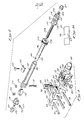
- Figure 1 is a perspective view of the improved external fixation device according to the present invention, installed upon a fractured-bone, and illustrates the relative orientation of the arcuate frame segments, pin holders, adjustment rods and pins with the bone;
- Figure 2 is a plan view of the two preferred angular lengths of the arcuate frame segments of the fixation device oriented to be rigidly connected together;
- Figure 2A is a perspective view of a frame- connector utilized to rigidly interconnect the two arcuate frame segments of Figure 2;
- Figure 3 is a partially exploded perspective view of the pin holder of the fixation device illustrating its detailed construction and showing its interconnect- - ion with the arcuate frame segment;
- Figure 3A is a side view of a portion of a pin holder showing the shape of the pocket therein;
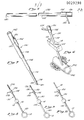
- Figure 4 is an exploded perspective view of the adjustable connecting rod of the fixation device;
- Figure 5 is a perspective view of a pin sheath which is insertable into the pin holder of Figure 3;
- Figure 6 is a perspective view of the sheath of Figure 5 installed within the pin holder and extending downward through the soft tissue into the outer surfaces of the bone;
- Figure 7 is a perspective view of a bone depth gauge;
- Figure 8 is a schematic view of the sheath of Figure 5 being utilized as a drill guide;
- Figure 9 is a schematic view of the sheath of Figure 5 being utilized in conjunction with the bone depth probe of Figure 7 to accurately measure the diameter of the bone; and
- Figure 10 is a schematic view of the sheath of Figure 5 being utilized to guide the insertion of a pin into the bone.
- Figure 1 depicts the improved
external fixation device 10 of the present invention composed generally of a pair ofarcuate frame segments 12, which are disposed about a fracturedbone 13 havingplural pin holders 14 andmultiple adjustment rods 16 attached thereto. As shown, thepin holders 14 are positioned at various locations upon thearcuate frame segments 12, and mount plural transfixingpins 18 which extend completely through the fracturedbone 13 and outward beyond the soft tissue (not shown) surrounding thebone 13 and plural half pins 20.which.extend through the fracturedbone 13 but protrude only a short distance beyond the lower surface thereof. - The transfixing
pins 18 andhalf pins 20 are arranged upon thebone 13 to provide two independent pin groups which are disposed on opposite sides of thebone fracture 15 and rigidly attached by thepin holders 14 to a respective one of thearcuate frame segments 12. The relative lateral and angular position of thearcuate frame segments 12 is maintained by theplural adjustment rods 16 which are rigidly attached at opposite ends thereof to each of thearcuate frame segments 12. The specific orientation of theframe segments 14 about the fracturedbone 13 as well as the number ofpins apparatus 10 as shown in Figure 1, is merely disclosed as by way of example, with adaptations and modifications of the basic structure being contemplated to suit the particular fracture type and fracture location upon the patient. - Referring to Figure 2, the detailed construction of the
arcuate frame segments 12 of the fixation device is illustrated. In the preferred embodiment, theframe segments 12 are typically fabricated in two arcuate lengths, 240° and 120°; designated by thenumerals 12 and 12A respectively in Figure 2;which may be utilised either singularly as shown in Figure 1, or conjunctively as represented in Figure 2 to yield the proper frame orientation to suit the particular type and location ofbone fracture 15. Of course, the frame segments may be in various lengths. Both of theframe segments 12 and 12A are also provided in different diameter sizes to account for variations in the fracture location and body size of the patient with the various sizes being readily interchangeable to permit the proximal and distal frame members, located on opposite sides of the fracture to be of unequal diameter size. - The
arcuate frame segments central web portion 30 and a pair of flange portions 32 (best shown in Figure 2 and 3) sized having standard cross-sectional dimensions for all of the various segment sizes. A plurality ofmounting apertures 34 are formed in theweb portion 30 and symmetrically spaced at approximately 8° intervals throughout the length of theframe segments segments - In the particular instances_which require an entire circular support frame to be disposed about the soft tissue of a patient, the
arcuate frame segments link 40 illustrated in Figure 2a. As shown the connectinglink 40 includes a pair of threadedstuds 42 the diameter of which is sized slightly less than the diameter of theplural apertures 34 formed in theframe segments link 40 may span between opposite ends of the 240°ring segment ring segment 12a (as represented by the phantom lines in Figure 2), with the pair of threadedstuds 42 being inserted in theendmost apertures 34 formed in thesegments acorn fasteners 44 may be threadingly mounted upon thestuds 42 from the reverse side of theframe segments lower bearing surface 46 being received between theflange portions 32 of theframe segments center webs portions 30. - As shown in Figure 3, the
pin holder 14 of the fixation device is formed having anelongate body section 50 including a flange 51 at its proximal end. The flange 51 is provided with amounting boss 52 and threaded stud 54 which are sized to be received between theflange porrion s 32 of thearcuate segment 12 and within theaperture 34 of theweb portion 30 respectively. - The length of the
boss 52 is slightly less than the distance from theoutboard edge 58 of theflange portions 32 to theweb 30 such that the lower surface 56 of the flange 51 may abut theoutboard edges 58 of thearcuate frame segment 12. - With the threaded stud 54 of the
pin holder 14 inserted through theaperture 34, anacorn fastener 60 may be threaded onto the stud 54 from the reverse side of thearcuate segment 12 thereby rigidly mounting thepin holder 14 to the frame segment. As will be recognized, by such an arrangement, thepin holder 14 may be selectively rotated about the axis of the threaded stud 54 and subsequently locked in a desired orientation by the manual tightening of the acorn fastener 60 against theweb portion 30 of thearcuate segment 12. - The
body section 50 of thepin holder 14 includes a plurality ofapertures 62 which extend through its width, each sized to loosely receive a conventional transfixing orhalf pin apertures 62 is, in one preferred embodiment, formed with a V-shapedwall portion 64 having an included angle of approximately 1200. - A,plurality of
rectangular pockets 66 are additionally formed in thebody section 50 of thepin holder 14 perpendicular to theapertures 62. Thepockets 66 extend from the upper surface of thepin'holder 14 and terminate at a distance below theapertures 62 but above the lower surface of thebody member 50. Pockets of any other non-circular shape may, of course, be used. - Each of the
pockets 66 is sized to slidingly receive apin lock member 68 having a rectangular shapedbody 70 and a threadedstud 72. Thebody 70 of thepin lock member 68 includes acentral aperture 74 which extends through thepin lock 68 and is provided with a V-shaped wall portion 76 adjacent its upper end which is formed in the manner previously described in relation to the V-shapedwall 64 of theapertures 62. The threadedstud 72 of thepin lock 68 extends through anaperture 67, see Figure 3a, formed centrally between the lower surface of thepocket 66 and the bottom surface of thebody portion 50 of thepin holder 14. - In operation, the
pin lock 68 may be loosely positioned within one of thepockets 66 formed in thebody 50, and apin aperture 62 formed in thebody portion 50 as well as theaperture 74 formed in thepin lock 68. Subsequently, anacorn fastener 80 may be threadingly mounted onto thestud 72 causing thepin lock 68 to be pulled tightly downward against thepin 18. Thepin 18 is axially centered within thepin holder 14 and is securely locked into position by the concentrated forces being exerted along the clamping lines corresponding to the contact surfaces between the outer diameter of thepin 18 with the apertures in the body and the pin lock. The "V" shaped wall portions improve the rigidity of this action. - As will be recognized, each of the
pockets 66 formed in thepin holder 14 includes apin lock member 68 which facilitate the remainingpins aperture 62 to be securely locked into position. Additionally, by this particular arrangement,individual pins pin holder 14 by merely loosening theappropriate acorn fastener 80 of one of thepin lock members 68. Further, the fixation device may be provided with single, dual and triple pin receivingpin holders 14 which are formed in the manner previously described. - In Figure 4, the detailed construction of the
adjustable rod 16 of the fixation device is illustrated. Therod 16 comprises an inner andouter tube member outer tube 92 includes anelongate slot 94 which extends substantially throughout its length. Theinner tube 90 is formed having aninner aperture 96 which terminates adjacent its outer end and includes a threadedaperture 98 positioned perpendicular to its axis. - The inner and
outer tubes fastener 100 which cooperates with asaddle 102 and extends through theslot 94 and into theaperture 98. By manually tightening the threadedfastener 100,'the'saddle 102 engages the outer diameter of theouter tube 92 and positively locks theinner tube 90 at any location along the length of theslot 94. - The opposite end of the
inner tube 90 includes a .knurled knob 104 which is mounted thereby by means to permit rotation of theknob 104 about thetube 90 while maintaining the axial position of theknob 104 at the end of thetube 90. Theknob 104 is provided with a. .threadedcentral aperture 106 which threadingly engages a lead screw 108. The diameter of theaperture 96 of theinner tube 90 is sized to be slightly greater than the maximum diameter of the lead screw 108 such that manual turning of theknob 104 causes the lead screw 108 to freely reciprocate axially within theaperture 96 of thetube 90. - The outer ends of the.
outer tube 94 and lead screw 108 are each rigidly attached to aclevis 110 formed in a conventional manner. Eachclevis 110 mounts atrunion 112 as by way of a threadedtrunion pivot 114 andfastener 116. Thetrunions 112 additionally mount a similarly formedclevis 118 having atrunion pivot 120 andfastener 122 cooperating therewith. Eachclevis 118 is provided with a mountingflange 124 and threadedstud 126 which permit the entireadjustment rod assembly 16 to be secured to the pair ofarcuate frame segments 12 in a manner previously described in relation to thepin holder 14 mounting. - By this particular arrangement, it will be recognized that connecting
rod 16 may be loosely attached to thearcuate frame segments 12 with the trunion clevis assemblies at opposite ends of therod 16 forming universal joints to permit angular and lateral articulation of theframe segments 12. Additionally, the length of theadjustment rod 16 may be varied first by a fast adjustment provided by the reciprocation of theinner tube 90 within theouter tube 92, and secondly by the fine adjustment provided by the reciprocation of the lead screw 108 within theinner tube 90. Once the correct positioning of theadjustment rod 16 is obtained, the entire assembly may be rigidly locked into position by the manual tightening of the threadedfasteners - Referring to Figure 5,
sheath 130 is specifically designed for use with thepin holder 14 during installation of thedevice 10 upon the patient. Thesheath 130 comprises an elongatetubular member 132, having an inside diameter slightly greater than.the diameter of the transfixing and half pins 18 and 20 respectively, and'an outside diameter slightly less than the diameter of theapertures pin holder 14 andpin lock member 68 respectively. - One end of the
sheath 130 includes a pair of mountingcollars sheath 130 and mount atab 138 which extends radially outward to form a handle for thesheath 130. The opposite end of thetube member 132 is formed having a. sharpenedtoothlike edge 140 which is adapted to anchor itself into the cortices of the bone. The use of thesheath 130 in combination with thepin holder 14 of the fixation device, provides an alignment process for the drilling and placement of pins through thebone 13, and prevents excessive damage to the soft tissue surrounding the bone. - A
bone depth gauge 150 which is preferably utilized in combination with thesheath 130 is depicted in Figure 7. Thedepth gauge 150 comprises atubular handle member 152 which slidingly mounts anelongate probe 174. Theprobe 174 is sized to be substantially greater in length than thesheath 130 and has a maximum diameter slightly less than the inside diameter of thesheath 130. The lowermost end of theprobe 174 is provided with a reduceddiameter section 176 which terminates at its lowermost end in a taperedshank 178. A bluntbuttonlike end member 180 is mounted to the lower end of the taperedshank 178 having anupper surface 182 which forms a shoulder substantially perpendicular to the axis of theprobe 174. - The opposite end of the
probe 174 is provided with anindicator tab 184 which is attached to theprobe 174 by a pair of wire mounts 186 sized to reciprocate through theslot 188 formed in thehandle member 152. The indicator tab 184 is adapted to be gripped by the physician, wherein movement of thetab 184 causes theprobe 174 to reciprocate axially throughout the length. of thehandle member 152. Thehandle member 152 is additionally provided with a series of graduations along itsouter diameter 190 which may be utilized in conjunction with thetab indicator 184 to determine the bone diameter. - For purposes of illustration, the
device 10 will be described in relation to a typicallong bone fracture 15 as depicted in Figure 1, however, the same installation and operation are applicable to other bone fractures as well. - After the extent and location of the
bone fracture 15 has been determined, the proper diameter size and arcuate length of thearcuate frame segments 12 to be utilized upon the patient must be selected. Typically, the diameter size is selected to position thesegments 12 as close as possible to the soft tissue of the patient while allowing for usual swelling during healing. The arcuate length of thesegments 12 are determined by the particular types of bone fracture. - A small incision is made in the.soft tissue at a location spaced on one side of the fracture site, and a hole of proper size to receive a
transfixing pin 18 is drilled entirely through thebone 13 preferably oriented perpendicular to thebone 13. A first transfixingpin 18 may then be inserted through the incision and threaded into the cortices of thebone 13 having opposite ends of the transfixingpin 18 extending outward a short distance beyond the soft tissue surrounding thebone 13. - With the first transfixing
pin 18 positioned within thebone 13, a pair ofpin holders 14 may be mounted onto the opposite ends of the transfixingpin 18 which extend outboard of the soft tissue and preliminarily maintained .in place by the finger tightening of theappropriate acorn fasteners 80 of thepin holders 14. The pair ofpin holders 14 are then attached to one of the arcuate frame segments 12 (e.g., the proximal frame segment) at positions approximately 90° from the center of theframe segment 12. Minor movement of thepin holder 14 along the length of the transfixingpin 18 to permit insertion of the threaded studs 54 into thesegment apertures 34 may be accommodated by slightly loosening theacorn fastener 80 and thepin holders 14 may be secured to theframe 12 by manual tightening of thesimilar acorn fasteners 60 onto the rear side of theframe 12. During this initial mounting procedure, thearcuate support segment 12 should be substantially centered about the soft tissue of the extremity, and disposed in a plane substantially perpendicular to thebone 13. - Once the
frame 12 has been preliminarily mounted to the transfixingpin 18 by way of thepin holders 14, two additional transfixing pins 18 may be inserted through thebone 13 and attached to thepin holders 14. The preferred procedure for facilitating the placement of these additional transfixing pins 18 is illustrated schematically in Figures 6, 8 and 10 wherein thepin holder 14 attach to theframe segment 12 is utilized in conjunction withsheath 130 to accurately align and position thepin 18 through thebone 13. - The first step in this procedure is the insertion and preliminary locking of the
tubular portion 132 of thesheath 130 into theadjacent aperture 62 formed in thepin holder 14. An incision is made where thelower end 140 of thesheath 130 contacts the soft tissue and, thesheath 130 is pressed through the soft tissue to contact thebone 13. Theuppermost collar 136 of thesheath 130 may then be moderately tapped downward, causing theknife edge end 140 of the sheath to attach itself to thebone 13. Theouter diameter 132 of thesheath 130 is registered within-theaperture 62 of the pin. holder 14- thereby maintainingsheath 130 in a parallel orientation to the first transfixingpin 18 locked within the.pin holder 14. - With the
sheath 130 in place, adrill 200 may be inserted through the open end of thesheath 130 and a hole formed through the bone 13 (as shown in Figure 8). As will be recognized, during this drilling procedure, thesheath 130 acts as a drill guide to prevent wandering of the drill through thebone 13. Subsequently, thedrill 200 may be removed from thesheath 130 and.the transfixing pin -18 may be inserted therein and threaded thorugh thebone 13. Theacorn fastener 80 holding thesheath 130 in the pin holder.14 may be manually loosened and thesheath 130 may be withdrawn from the soft tissue and removed from thepin holder 14 leaving the transfixingpin 18 in place. Theacorn fastener 80 may then be retightened thereby securely clamping the transfixingpin 18 in place. This above procedure may be repeated for the third transfixingpin 18 in the assembly such that three parallel transfixing pins 18 extend through thebone 13 and are affixed to the proximalarcuate frame segment 12 by the pair ofpin holders 14. - With the three parallel transfixing pins mounted to the
bone 13, an additional pair of half pins 20 may be inserted through thebone 13 extending in a plane substantially perpendicular to the plane of the previously positioned transfixing pins 18. The insertion of the half pins is accomplished in a manner similar to the transfixing pins 14; however, adual pin holder 14 is utilized in place of thetriple pin holder 14 previously described. As shown in Figure 1, thedual pin holder 14 is positioned at the approximate center line of the proximalarcuate frame segment 12 preferably located at no more than a 30° angle therefrom. Thedual pin holder 14 is formed in the same manner as the triple pin holder 14 (shown in Figure 3) except that the center line of thepin receiving apertures 62 are offset to facilitate the half pins 20 entering thebone 13 at a location between the transfixing pins 18. - As with the insertion of the previous transfixing pins 18, the
sheath 130 is inserted into theaperture 62 formed in thedual pin holder 14 and an incision is made in the soft tissue beneath the end of thesheath 130. Thesheath 130 is subsequently inserted through the soft tissue and lodged in thebone 13. The drilling of the hole through thebone 13 may then be accomplished using thesheath 130 as a drill guide. - The half pins 20 extend through the soft tissue only on one side of the
bone 13 and must be accurately positioned within thebone 13 to contact both cortices 202 (shown in Figure 6) while extending only a minimum distance below the lower surface of the bone. As such, prior to the insertion of the half pins, it is necessary to accurately determine the bone diameter. In the preferred embodiment this diameter determination is readily facilitated by use of abone depth gauge 150 of Figure 7. - As previously mentioned, the
probe 174 of thedepth gauge 150 is sized to be inserted within the sheath 130 (as shown in Figure 9). By gripping thehandle portion 152 of thedepth gauge 150, the surgeon may lower theprobe end 176 of thedepth gauge 150 downward through thesheath 130 to contact the blunt button-like 180 upon the top surface of the bone. Upon contact therewith, the surgeon may visually inspect one end of theindicator tab 184 to obtain an initial reading on the graduated scale. Subsequently, theprobe end 176 of thedepth gauge 150 may be reciprocated through the previously drilled hole in the bone, by manual sliding of the indicator tab relative thehandle 152 until theshoulder 182 of theprobe end 180 hooks the.lower outside surface of abone 13. Theindicator tab 184 may then be visually inspected again, and the difference in the two. readings on the graduatedscale 190 will represent the outside diameter ofbone 13. - The
depth gauge 150 may then be removed from thesheath 130 and the propersize half pin 20 lowered through thesheath 130 and inserted into thebone 13. The bone diameter having been determined by thedepth gauge 150, the half pin threadingly engages bothcortices 202 of the bone and is made to protrude only a short distance beyond thebone 13 to eliminate damage of muscle tissue on the undersurface of the bone or the rupturing of an artery. Thesheath 130 may then be removed from thepin holder 14, and theacorn fastener 80 retightened to securely mount the pin to thepin holder 14. Similarly, the second half pin may be inserted into thebone 13 in the same manner and locked in position upon thepin holder 14. - By such a procedure, it will be recognized that the
bone 13 is positively located from two substantially perpendicular directions, or at other selected angles, to the proximalarcuate support segment 12 with thesupport segment 12 providing a rigid structure which prevents movement of the proximal end of thebone 13 relative thesupport frame 12. Additionally, it will be recognized that by use of thesheath 130 during the installation process, the pin holes may be drilled and accurately located with only minimal disturbance of the soft tissues surrounding thebone 13 thereby preventing any unnecessary damage to the soft tissue. - The above procedures may be repeated for the distal end of the
bone 13 whereby a second seri.es of transfixingpins 18 and half pins 20 are rigidly attached to thebone 13 as well as the distalarcuate frame segment 12. As such, both the proximal and distal ends of thebone 13 are rigidly affixed to a respectivearcuate frame segment 12. - Subsequently, three
adjustment rods 16 may be loosely attached to extend between the pair ofarcuate frame segments 12 by inserting the threadedstuds 126 located on opposite ends of the rods through arespective aperture 34 formed in theframe segments 12 and loosely tightening the respective acorn fasteners 60 (Figure 4) onto theframe section 12. During this initial connection, thescrew fastener 100 upon thesaddle 102 is loosened to provide free reciprocation of theinner tube 90 within theouter tube 94 of the connectingrod 16 and theknurled knob 104 is preliminarily positioned midway along the length of the lead screw 108. Additionally, the clevis andtrunion assembly nuts rod 16 at its opposite ends. - The
fracture 15 may then be set by grasping both of thearcuate frame segments 12 and moving the same relative one another until proper alignment of the bone ends in the vicinity of thefracture 15 is obtained. Thescrew fasteners 100 may then be securely tightened thereby locking theinner tubes 90 in position within theouter tubes 92 of the connectingrods 16 and the clevistrunion assembly nuts adjustable rods 16 may then be manually turned causing their respective lead screws 108 to be reciprocated either inward or outward within theinner tube 90 to apply distraction.-or compression to thebone fracture 15. Subsequently, all of the acorn fasteners may be tightly set by use of a conventional wrench to maintain the set configuration of theexternal fixation device 10. - As will be recognized, by such an installation, the
bone 13 is completely immobilized with the majority of the compression, tensile and bending forces applied during bone positioning being carried by thearcuate frame segments 12. Additionally, due to theframe segments 12 extending proximal to the soft tissue of the patient, patient discomfort is minimized and access to the soft tissue in the vicinity of thefracture 15 is readily facilitated. Thus, needed procedures such as grafting and irrigation may be readily accomplished without interference of thedevice 10. Further, due to thepin holder 14 design which permits independent locking of thepins - Those skilled in the art will recognize that the
device 10 of the present invention may be readily modified with varying pin locations, and number of frame segments and adjustment rods utilized to facilitate the proper external fixation for the particular boma fracture, and such modifications are encompassed within the scope of the present invention. - Additionally, the invention relates to a novel method which permits proper alignment, drilling and placement of the pins into the bone with only minimal damage to soft tissue, as well as a bone depth gauge which is insertable within the sheath to accurately measure the bone diameter thereby facilitating proper pin selection and insertion into the bone.
Claims (14)
Applications Claiming Priority (2)
| Application Number | Priority Date | Filing Date | Title |
|---|---|---|---|
| US06/085,996 US4308863A (en) | 1979-10-18 | 1979-10-18 | External fixation device |
| US85996 | 1979-10-18 |
Publications (2)
| Publication Number | Publication Date |
|---|---|
| EP0029298A1 true EP0029298A1 (en) | 1981-05-27 |
| EP0029298B1 EP0029298B1 (en) | 1985-04-17 |
Family
ID=22195293
Family Applications (1)
| Application Number | Title | Priority Date | Filing Date |
|---|---|---|---|
| EP80303670A Expired EP0029298B1 (en) | 1979-10-18 | 1980-10-17 | External fixation device, especially for bone fractures |
Country Status (4)
| Country | Link |
|---|---|
| US (1) | US4308863A (en) |
| EP (1) | EP0029298B1 (en) |
| DE (1) | DE3070520D1 (en) |
| ES (1) | ES496062A0 (en) |
Cited By (20)
| Publication number | Priority date | Publication date | Assignee | Title |
|---|---|---|---|---|
| FR2573977A1 (en) * | 1984-12-04 | 1986-06-06 | Medicuba | ORTHOPEDIC EXTERNAL FIXING APPARATUS, IN PARTICULAR FOR POSITIONING FRACTURE BONES |
| FR2574654A1 (en) * | 1984-12-18 | 1986-06-20 | Orthofix Srl | ORTHOPEDIC APPARATUS FOR EXTERNALLY FIXED BONE OR FRACTURE BONE PARTS WITH A WIDE RANGE OF ADAPTABILITY |
| FR2576774A1 (en) * | 1985-02-07 | 1986-08-08 | Issoire Aviat Sa | Device for three-dimensional positioning of any two pieces, in particular two pieces of bone, and allowing modification of the said positioning |
| EP0190990A1 (en) * | 1985-01-24 | 1986-08-13 | Jaquet Orthopedie S.A. | Arcuate segment and external bone anchoring splint for osteosynthesis and osteoplasty |
| FR2577793A1 (en) * | 1985-02-22 | 1986-08-29 | Realisations Electro Mecanique | EXTERNAL FIXER DEVICE FOR ORTHOPEDIC USE |
| FR2653988A1 (en) * | 1989-11-07 | 1991-05-10 | Lacaffiniere Jean Yves De | External radiotransparent device for provisional reduction and retention for centromedullary osteosynthesis of fractures of the tibia |
| FR2657780A1 (en) * | 1990-02-05 | 1991-08-09 | Belin Jacques | SURGICAL TECHNICAL ASSISTANCE DEVICE AND METHOD FOR USING THE SAME. |
| WO1997030650A1 (en) * | 1996-02-21 | 1997-08-28 | Orthofix S.R.L. | External fixator apparatus for bone surgery |
| WO1998012975A2 (en) * | 1996-09-26 | 1998-04-02 | Aleksandar Tosic | Articulated external orthopedic fixation system and method of use |
| WO2001015611A1 (en) * | 1999-08-30 | 2001-03-08 | Smith & Nephew, Inc. | Six axis external fixator strut |
| WO2008070826A1 (en) * | 2006-12-07 | 2008-06-12 | Juvent, Inc. | Apparatuses for combining limb shaping with vibrational treatment of bones |
| EP2249721A1 (en) * | 2008-02-12 | 2010-11-17 | Texas Scottish Rite Hospital For Children | Fast adjust external fixation connection rod |
| US7942835B2 (en) | 2006-03-08 | 2011-05-17 | American Medical Innovations, L.L.C. | System and method for providing therapeutic treatment using a combination of ultrasound and vibrational stimulation |
| US8864750B2 (en) | 2008-02-18 | 2014-10-21 | Texas Scottish Rite Hospital For Children | Tool and method for external fixation strut adjustment |
| US9155559B2 (en) | 2008-02-08 | 2015-10-13 | Texas Scottish Rite Hospital For Children | External fixator strut |
| JP2016501051A (en) * | 2012-11-13 | 2016-01-18 | テキサス スコティッシュ ライト ホスピタル フォー チルドレン | External fixed connecting rod for quick and gradual adjustment |
| US9295493B2 (en) | 2008-02-05 | 2016-03-29 | Texas Scottish Rite Hospital For Children | External fixator ring |
| US9443302B2 (en) | 2010-08-20 | 2016-09-13 | Amei Technologies, Inc. | Method and system for roentgenography-based modeling |
| EP3698743A1 (en) * | 2019-02-19 | 2020-08-26 | Arthrex Inc | Alignment device for bones |
| WO2022151606A1 (en) * | 2021-01-12 | 2022-07-21 | 中国人民解放军空军军医大学 | Multi-angle-fixing and length-adjustable wartime simple unilateral external fixator |
Families Citing this family (113)
| Publication number | Priority date | Publication date | Assignee | Title |
|---|---|---|---|---|
| US4393868A (en) * | 1981-02-20 | 1983-07-19 | Ace Orthopedic Manufacturing Inc. | Colles fracture fixature device |
| ES8302449A2 (en) * | 1981-12-09 | 1983-01-16 | Lazo De Zbikowski Juan | Functional attachment system for osteosynthesis |
| ATE48234T1 (en) * | 1984-02-08 | 1989-12-15 | Zausmed Inc | BONE GROWTH STIMULATOR. |
| US4889111A (en) * | 1984-02-08 | 1989-12-26 | Ben Dov Meir | Bone growth stimulator |
| US4895141A (en) * | 1984-04-26 | 1990-01-23 | Harrington Arthritis Research Center | Unilateral external fixation device |
| US4757809A (en) * | 1984-04-26 | 1988-07-19 | Orthotic Limited Partnership | Pin clamp |
| US4747400A (en) * | 1984-04-26 | 1988-05-31 | Harrington Arthritis Research Center | External fixation device |
| US4644943A (en) * | 1984-07-20 | 1987-02-24 | Regents Of The University Of Minnesota | Bone fixation device |
| FR2572929B1 (en) * | 1984-11-15 | 1987-09-04 | Jawish Roger | EXTERNAL FIXER FOR BONES AND JOINTS |
| US4923458A (en) * | 1986-04-17 | 1990-05-08 | Ace Medical Company | Surgical fixation pin tension adjuster |
| DE3701533A1 (en) * | 1987-01-21 | 1988-08-04 | Medi System Gmbh | OSTEOSYNTHESIS TOOLS |
| US4863473A (en) * | 1988-04-06 | 1989-09-05 | Osteotech, Inc. | Osteoprosthesis for cadaver, and method |
| IT1234756B (en) * | 1989-03-17 | 1992-05-26 | Orthofix Srl | EXTERNAL FIXER PARTICULARLY SUITABLE TO BE APPLIED ON THE BASINS. |
| US4907577A (en) * | 1989-04-03 | 1990-03-13 | Wu Shing Sheng | Spinal transpedicle drill jig |
| US5382248A (en) * | 1992-09-10 | 1995-01-17 | H. D. Medical, Inc. | System and method for stabilizing bone segments |
| US5275600A (en) * | 1992-10-05 | 1994-01-04 | Zimmer, Inc. | Telescoping rod to rod coupler for a spinal system |
| US5658283A (en) * | 1995-02-15 | 1997-08-19 | Huebner; Randall J. | External fixator for repairing fractures |
| US5662649A (en) * | 1995-02-15 | 1997-09-02 | Huebner; Randall J. | External fixator for repairing fractures of distal radius and wrist |
| US5624440A (en) * | 1996-01-11 | 1997-04-29 | Huebner; Randall J. | Compact small bone fixator |
| US6162224A (en) * | 1995-02-15 | 2000-12-19 | Acumed, Inc. | External fixator for repairing fractures of distal radius and wrist |
| US5976134A (en) * | 1995-06-01 | 1999-11-02 | Huebner; Randall J. | External fixator for repairing fractures |
| US6171309B1 (en) | 1995-02-15 | 2001-01-09 | Acumed, Inc. | External fixator for repairing fractures of distal radius and wrist |
| US5545162A (en) * | 1995-02-15 | 1996-08-13 | Huebner; Randall J. | External fixator for repairing fractures of distal radius and wrist |
| US5766173A (en) * | 1993-06-10 | 1998-06-16 | Texas Scottish Rite Hospital For Children | Distractor mechanism for external fixation device |
| US5496319A (en) * | 1994-06-27 | 1996-03-05 | Zimmer, Inc. | External fixation apparatus |
| US5591164A (en) * | 1994-12-22 | 1997-01-07 | Zimmer, Inc. | External fixation apparatus and system |
| US5971984A (en) * | 1995-03-01 | 1999-10-26 | Smith & Nephew, Inc. | Method of using an orthopaedic fixation device |
| US5728095A (en) * | 1995-03-01 | 1998-03-17 | Smith & Nephew, Inc. | Method of using an orthopaedic fixation device |
| NZ303050A (en) * | 1995-03-01 | 1998-05-27 | Smith & Nephew Inc | Spatial frame with a first element positionable relative to a second element |
| GB2300357A (en) * | 1995-05-01 | 1996-11-06 | Biomet Ltd | Bone fixation system with data logging device |
| US5662650A (en) | 1995-05-12 | 1997-09-02 | Electro-Biology, Inc. | Method and apparatus for external fixation of large bones |
| US5743898A (en) * | 1995-05-12 | 1998-04-28 | Electro-Biology, Inc. | Method and apparatus for external fixation of small bones |
| US5976125A (en) * | 1995-08-29 | 1999-11-02 | The Cleveland Clinic Foundation | External distractor/fixator for the management of fractures and dislocations of interphalangeal joints |
| WO1997012568A1 (en) * | 1995-10-02 | 1997-04-10 | Remmler Daniel J | Implantable apparatus, matrix and method for correction of craniofacial bone deformities |
| US5681352A (en) * | 1996-03-06 | 1997-10-28 | Kinetikos Medical Incorporated | Method and apparatus for anchoring surgical ties to bone |
| US6159210A (en) * | 1997-01-14 | 2000-12-12 | Research Corporation Technologies, Inc. | Bone fixation pin with rotary cutting tip |
| US5797908A (en) * | 1997-02-04 | 1998-08-25 | Bristol-Myers Squibb Company | External fixator assembly and clamp therefor |
| US5891143A (en) | 1997-10-20 | 1999-04-06 | Smith & Nephew, Inc. | Orthopaedic fixation plate |
| CA2332557C (en) | 1998-05-19 | 2007-04-17 | Synthes (U.S.A.) | Telescopic body for an external fixation system |
| US6030386A (en) * | 1998-08-10 | 2000-02-29 | Smith & Nephew, Inc. | Six axis external fixator strut |
| BE1013222A3 (en) * | 2000-01-11 | 2001-11-06 | Mommaerts Maurice Yves | APPARATUS FOR INTRA-ORAL DISTRACTIEOSTEOTOMIE to widen the upper jaw. |
| US6565564B2 (en) * | 2000-12-14 | 2003-05-20 | Synthes U.S.A. | Multi-pin clamp and rod attachment |
| GB0107708D0 (en) * | 2001-03-28 | 2001-05-16 | Imp College Innovations Ltd | Bone fixated,articulated joint load control device |
| US7147640B2 (en) * | 2003-03-12 | 2006-12-12 | Acumed Llc | External fixator |
| US7261713B2 (en) | 2001-10-09 | 2007-08-28 | Synthes (Usa) | Adjustable fixator |
| US6860883B2 (en) * | 2002-02-11 | 2005-03-01 | Pioneer Laboratories, Inc. | External fixation apparatus and method |
| EP1549235A4 (en) * | 2002-09-17 | 2010-05-05 | Extraortho Inc | Unilateral fixator |
| US8419732B2 (en) * | 2002-11-14 | 2013-04-16 | Sixfix, Inc. | Method for using a fixator device |
| US8603017B2 (en) | 2005-03-07 | 2013-12-10 | American Medical Innovations, L.L.C. | Vibrational therapy assembly for treating and preventing the onset of deep venous thrombosis |
| US8152834B2 (en) * | 2005-04-13 | 2012-04-10 | Synthes Usa, Llc | Forceps and system using same |
| HU3082U (en) * | 2005-05-24 | 2006-04-28 | Istvan Dr Kadas | Device for covered screwing of shortening fractures |
| US7749224B2 (en) * | 2005-12-08 | 2010-07-06 | Ebi, Llc | Foot plate fixation |
| US7422593B2 (en) * | 2005-12-08 | 2008-09-09 | Ebi, L.P. | External fixation system |
| US8858600B2 (en) * | 2006-06-08 | 2014-10-14 | Spinadyne, Inc. | Dynamic spinal stabilization device |
| US8795210B2 (en) | 2006-07-11 | 2014-08-05 | American Medical Innovations, L.L.C. | System and method for a low profile vibrating plate |
| US7730690B2 (en) * | 2006-12-27 | 2010-06-08 | Usg Interiors, Inc. | Compression post assembly for wind up-lift of suspension soffits |
| US8709090B2 (en) | 2007-05-01 | 2014-04-29 | Moximed, Inc. | Adjustable absorber designs for implantable device |
| US9907645B2 (en) * | 2007-05-01 | 2018-03-06 | Moximed, Inc. | Adjustable absorber designs for implantable device |
| US8123805B2 (en) | 2007-05-01 | 2012-02-28 | Moximed, Inc. | Adjustable absorber designs for implantable device |
| US20080275557A1 (en) * | 2007-05-01 | 2008-11-06 | Exploramed Nc4, Inc. | Adjustable absorber designs for implantable device |
| US20080275567A1 (en) * | 2007-05-01 | 2008-11-06 | Exploramed Nc4, Inc. | Extra-Articular Implantable Mechanical Energy Absorbing Systems |
| US20100137996A1 (en) * | 2007-05-01 | 2010-06-03 | Moximed, Inc. | Femoral and tibial base components |
| US7655041B2 (en) * | 2007-05-01 | 2010-02-02 | Moximed, Inc. | Extra-articular implantable mechanical energy absorbing systems and implantation method |
| US20110245928A1 (en) | 2010-04-06 | 2011-10-06 | Moximed, Inc. | Femoral and Tibial Bases |
| US10022154B2 (en) * | 2007-05-01 | 2018-07-17 | Moximed, Inc. | Femoral and tibial base components |
| US8894714B2 (en) | 2007-05-01 | 2014-11-25 | Moximed, Inc. | Unlinked implantable knee unloading device |
| US8105356B2 (en) * | 2007-06-05 | 2012-01-31 | Spartek Medical, Inc. | Bone anchor with a curved mounting element for a dynamic stabilization and motion preservation spinal implantation system and method |
| US8979858B2 (en) * | 2007-08-21 | 2015-03-17 | Osteomed Llc | External mandibular distractor with rotational clamp |
| US7806843B2 (en) * | 2007-09-25 | 2010-10-05 | Marin Luis E | External fixator assembly |
| EP2085037B1 (en) * | 2008-02-01 | 2013-07-24 | Stryker Trauma SA | Telescopic strut for an external fixator |
| EP2085038B1 (en) * | 2008-02-01 | 2011-11-30 | Stryker Trauma SA | Ball joint for an external fixator |
| US8114077B2 (en) | 2008-02-01 | 2012-02-14 | Stryker Trauma Sa | Clamping pin |
| EP2110090A1 (en) * | 2008-04-18 | 2009-10-21 | Stryker Trauma SA | Radiolucent orthopedic fixation plate |
| EP2110089A1 (en) | 2008-04-18 | 2009-10-21 | Stryker Trauma SA | Orthopedic fixation plate |
| US20100087819A1 (en) * | 2008-10-07 | 2010-04-08 | Extraortho, Inc. | Forward Kinematic Solution for a Hexapod Manipulator and Method of Use |
| US20100179548A1 (en) | 2009-01-13 | 2010-07-15 | Marin Luis E | External fixator assembly |
| US9668868B2 (en) | 2009-08-27 | 2017-06-06 | Cotera, Inc. | Apparatus and methods for treatment of patellofemoral conditions |
| US9861408B2 (en) | 2009-08-27 | 2018-01-09 | The Foundry, Llc | Method and apparatus for treating canine cruciate ligament disease |
| US10349980B2 (en) | 2009-08-27 | 2019-07-16 | The Foundry, Llc | Method and apparatus for altering biomechanics of the shoulder |
| US9278004B2 (en) | 2009-08-27 | 2016-03-08 | Cotera, Inc. | Method and apparatus for altering biomechanics of the articular joints |
| BR112012004337A2 (en) | 2009-08-27 | 2016-03-15 | Cotera Inc | Method and apparatus for force redistribution in joints |
| US8679178B2 (en) * | 2009-10-20 | 2014-03-25 | Moximed, Inc. | Extra-articular implantable mechanical energy absorbing assemblies having two deflecting members and compliance member |
| US8523948B2 (en) | 2009-10-20 | 2013-09-03 | Moximed, Inc. | Extra-articular implantable mechanical energy absorbing assemblies having a tension member, and methods |
| US9078703B2 (en) * | 2009-11-25 | 2015-07-14 | Spine21 Ltd. | Spinal rod having a post-operative adjustable dimension |
| WO2011072249A1 (en) | 2009-12-11 | 2011-06-16 | Small Bone Innovations, Inc. | Ankle fusion device, instrumentation and methods |
| US8257353B2 (en) * | 2010-02-24 | 2012-09-04 | Wright Medical Technology, Inc. | Orthopedic external fixation device |
| EP2417924B1 (en) | 2010-08-11 | 2015-07-01 | Stryker Trauma SA | External fixator system |
| US8945128B2 (en) | 2010-08-11 | 2015-02-03 | Stryker Trauma Sa | External fixator system |
| US11141196B2 (en) | 2010-08-11 | 2021-10-12 | Stryker European Operations Holdings Llc | External fixator system |
| CN101983616B (en) * | 2010-11-19 | 2012-07-18 | 武汉康斯泰德科技有限公司 | Tensile pressure adjusting lever for external fixation |
| WO2012072756A1 (en) * | 2010-12-02 | 2012-06-07 | Fondazione Centro San Raffaele Del Monte Tabor | External bone fixator system |
| US9044270B2 (en) | 2011-03-29 | 2015-06-02 | Moximed, Inc. | Apparatus for controlling a load on a hip joint |
| KR101230124B1 (en) | 2011-03-31 | 2013-02-06 | 가톨릭대학교 산학협력단 | Supporting clamp for region of the fracture |
| US9649136B2 (en) * | 2011-07-15 | 2017-05-16 | Globus Medical, Inc. | Coupling devices and methods of using the same |
| US9820776B2 (en) * | 2012-05-04 | 2017-11-21 | Biomet Manufacturing, Llc | Ratcheting strut |
| US9474552B2 (en) * | 2012-05-04 | 2016-10-25 | Biomet Manufacturing, Llc | Ratcheting strut |
| US8906021B1 (en) * | 2012-08-20 | 2014-12-09 | Stryker Trauma Sa | Telescopic strut for an external fixator |
| US9101398B2 (en) | 2012-08-23 | 2015-08-11 | Stryker Trauma Sa | Bone transport external fixation frame |
| US9468466B1 (en) | 2012-08-24 | 2016-10-18 | Cotera, Inc. | Method and apparatus for altering biomechanics of the spine |
| EP2735276B1 (en) * | 2012-11-27 | 2018-09-05 | Stryker European Holdings I, LLC | Pediatric internal mandibular distractor |
| US10980655B1 (en) | 2013-03-14 | 2021-04-20 | Mdpo Llc | Dynamic foot plate |
| US10463522B2 (en) | 2013-03-14 | 2019-11-05 | Mdpo Llc | Dynamic foot plate |
| US10993868B2 (en) | 2013-03-14 | 2021-05-04 | Mdpo Llc | Dynamic foot plate |
| US10166053B2 (en) | 2014-12-30 | 2019-01-01 | Stryker European Holdings I, Llc | Distractor with bidirectional rotation control |
| US10010350B2 (en) * | 2016-06-14 | 2018-07-03 | Stryker European Holdings I, Llc | Gear mechanisms for fixation frame struts |
| US10874433B2 (en) * | 2017-01-30 | 2020-12-29 | Stryker European Holdings I, Llc | Strut attachments for external fixation frame |
| US10932820B2 (en) * | 2017-10-31 | 2021-03-02 | Life Spine, Inc. | Static strut and fixation constructs |
| CN108742804B (en) * | 2018-06-05 | 2020-04-07 | 天津大学 | Parallel external fixing support for fracture reduction |
| US10695095B2 (en) * | 2018-08-21 | 2020-06-30 | New Standard Device, LLC | Orthopedic strut with multiple attachment clamps |
| US10751089B2 (en) * | 2018-08-21 | 2020-08-25 | New Standard Device, LLC | Orthopedic strut with lockable swivel hinges |
| WO2020128581A1 (en) * | 2018-12-19 | 2020-06-25 | Newpharm S.R.L. | External fixator for bone fractures |
| US11826077B2 (en) * | 2020-03-23 | 2023-11-28 | Texas Scottish Rite Hospital For Children | External fixation strut |
| US11457950B2 (en) * | 2020-04-27 | 2022-10-04 | DePuy Synthes Products, Inc. | Locking system and method |
Citations (5)
| Publication number | Priority date | Publication date | Assignee | Title |
|---|---|---|---|---|
| GB421788A (en) * | 1933-06-29 | 1934-12-31 | Eloi Renevey | Apparatus for the treatment of bone-fractures |
| US1997466A (en) * | 1934-04-23 | 1935-04-09 | Harry Herschel Leiter | Surgical appliance |
| GB453633A (en) * | 1936-01-11 | 1936-09-15 | Alvin Wiltse Schenker | Improvements relating to apparatus for treating fractures of long bones |
| FR1577235A (en) * | 1967-10-10 | 1969-08-08 | ||
| GB1481585A (en) * | 1975-06-10 | 1977-08-03 | Tsnii Travmatol I Ortoped Im N | Apparatus for surgical treatment of fractured bones or of bone joints |
Family Cites Families (9)
| Publication number | Priority date | Publication date | Assignee | Title |
|---|---|---|---|---|
| US1517761A (en) * | 1920-04-06 | 1924-12-02 | Reed Roller Bit Co | Coupling for rotary-drill-stem sections |
| US2238870A (en) * | 1939-02-04 | 1941-04-15 | Herbert H Haynes | Ambulatory splint |
| US2406987A (en) * | 1943-01-04 | 1946-09-03 | Anderson Roger | Fracture splint |
| US2391537A (en) * | 1943-09-27 | 1945-12-25 | Anderson Roger | Ambulatory rotating reduction and fixation splint |
| US3516967A (en) * | 1968-10-28 | 1970-06-23 | Du Pont | Polyiminoimide and polyamide nitrile compositions |
| US3667716A (en) * | 1970-08-31 | 1972-06-06 | Steelcase Inc | Telescoping chair base |
| SU517196A1 (en) * | 1974-07-22 | 1977-09-25 | Центральный Ордена Трудового Красного Знамени Научно-Исследовательского Институт Травматологии И Ортопедии | Apparatus for repositioning and fixing bone fragments |
| US3993055A (en) * | 1975-06-11 | 1976-11-23 | Mstislav Vasilievich Volkov | Apparatus for surgical treatment of bone fractures and diseases |
| US4185623A (en) * | 1978-07-18 | 1980-01-29 | Oganesian Oganes V | Apparatus for restoration of hip joint mobility |
-
1979
- 1979-10-18 US US06/085,996 patent/US4308863A/en not_active Expired - Lifetime
-
1980
- 1980-10-17 DE DE8080303670T patent/DE3070520D1/en not_active Expired
- 1980-10-17 EP EP80303670A patent/EP0029298B1/en not_active Expired
- 1980-10-17 ES ES496062A patent/ES496062A0/en active Granted
Patent Citations (5)
| Publication number | Priority date | Publication date | Assignee | Title |
|---|---|---|---|---|
| GB421788A (en) * | 1933-06-29 | 1934-12-31 | Eloi Renevey | Apparatus for the treatment of bone-fractures |
| US1997466A (en) * | 1934-04-23 | 1935-04-09 | Harry Herschel Leiter | Surgical appliance |
| GB453633A (en) * | 1936-01-11 | 1936-09-15 | Alvin Wiltse Schenker | Improvements relating to apparatus for treating fractures of long bones |
| FR1577235A (en) * | 1967-10-10 | 1969-08-08 | ||
| GB1481585A (en) * | 1975-06-10 | 1977-08-03 | Tsnii Travmatol I Ortoped Im N | Apparatus for surgical treatment of fractured bones or of bone joints |
Cited By (33)
| Publication number | Priority date | Publication date | Assignee | Title |
|---|---|---|---|---|
| FR2573977A1 (en) * | 1984-12-04 | 1986-06-06 | Medicuba | ORTHOPEDIC EXTERNAL FIXING APPARATUS, IN PARTICULAR FOR POSITIONING FRACTURE BONES |
| FR2574654A1 (en) * | 1984-12-18 | 1986-06-20 | Orthofix Srl | ORTHOPEDIC APPARATUS FOR EXTERNALLY FIXED BONE OR FRACTURE BONE PARTS WITH A WIDE RANGE OF ADAPTABILITY |
| EP0190990A1 (en) * | 1985-01-24 | 1986-08-13 | Jaquet Orthopedie S.A. | Arcuate segment and external bone anchoring splint for osteosynthesis and osteoplasty |
| FR2576774A1 (en) * | 1985-02-07 | 1986-08-08 | Issoire Aviat Sa | Device for three-dimensional positioning of any two pieces, in particular two pieces of bone, and allowing modification of the said positioning |
| FR2577793A1 (en) * | 1985-02-22 | 1986-08-29 | Realisations Electro Mecanique | EXTERNAL FIXER DEVICE FOR ORTHOPEDIC USE |
| EP0194187A1 (en) | 1985-02-22 | 1986-09-10 | Jean-Marie Hardy | External fixation apparatus for orthopaedic use |
| FR2653988A1 (en) * | 1989-11-07 | 1991-05-10 | Lacaffiniere Jean Yves De | External radiotransparent device for provisional reduction and retention for centromedullary osteosynthesis of fractures of the tibia |
| FR2657780A1 (en) * | 1990-02-05 | 1991-08-09 | Belin Jacques | SURGICAL TECHNICAL ASSISTANCE DEVICE AND METHOD FOR USING THE SAME. |
| WO1997030650A1 (en) * | 1996-02-21 | 1997-08-28 | Orthofix S.R.L. | External fixator apparatus for bone surgery |
| WO1998012975A2 (en) * | 1996-09-26 | 1998-04-02 | Aleksandar Tosic | Articulated external orthopedic fixation system and method of use |
| WO1998012975A3 (en) * | 1996-09-26 | 1998-06-18 | Aleksandar Tosic | Articulated external orthopedic fixation system and method of use |
| WO2001015611A1 (en) * | 1999-08-30 | 2001-03-08 | Smith & Nephew, Inc. | Six axis external fixator strut |
| US7942835B2 (en) | 2006-03-08 | 2011-05-17 | American Medical Innovations, L.L.C. | System and method for providing therapeutic treatment using a combination of ultrasound and vibrational stimulation |
| US8043234B2 (en) | 2006-03-08 | 2011-10-25 | American Medical Innovations, L.L.C. | System and method for providing therapeutic treatment using a combination of ultrasound, electro-stimulation and vibrational stimulation |
| WO2008070826A1 (en) * | 2006-12-07 | 2008-06-12 | Juvent, Inc. | Apparatuses for combining limb shaping with vibrational treatment of bones |
| US9808289B2 (en) | 2008-02-05 | 2017-11-07 | Texas Scottish Rite Hospital For Children | External fixator ring |
| US9295493B2 (en) | 2008-02-05 | 2016-03-29 | Texas Scottish Rite Hospital For Children | External fixator ring |
| US9155559B2 (en) | 2008-02-08 | 2015-10-13 | Texas Scottish Rite Hospital For Children | External fixator strut |
| US9681892B2 (en) | 2008-02-08 | 2017-06-20 | Texas Scottish Rite Hospital For Children | External fixator strut |
| EP2249721A4 (en) * | 2008-02-12 | 2014-05-07 | Texas Scottish Rite Hospital | Fast adjust external fixation connection rod |
| EP3245966A1 (en) * | 2008-02-12 | 2017-11-22 | Texas Scottish Rite Hospital For Children | Connecting rod for an external fixation device |
| US9078700B2 (en) | 2008-02-12 | 2015-07-14 | Texas Scottish Rite Hospital For Children | Fast adjust external fixation connection rod |
| EP2249721A1 (en) * | 2008-02-12 | 2010-11-17 | Texas Scottish Rite Hospital For Children | Fast adjust external fixation connection rod |
| US9456849B2 (en) | 2008-02-12 | 2016-10-04 | Texas Scottish Rite Hospital For Children | Fast adjust external fixation connection rod |
| US8864750B2 (en) | 2008-02-18 | 2014-10-21 | Texas Scottish Rite Hospital For Children | Tool and method for external fixation strut adjustment |
| US9443302B2 (en) | 2010-08-20 | 2016-09-13 | Amei Technologies, Inc. | Method and system for roentgenography-based modeling |
| US9381042B2 (en) | 2012-11-13 | 2016-07-05 | Texas Scottish Rite Hospital For Children | External fixation connection rod for rapid and gradual adjustment |
| JP2016501051A (en) * | 2012-11-13 | 2016-01-18 | テキサス スコティッシュ ライト ホスピタル フォー チルドレン | External fixed connecting rod for quick and gradual adjustment |
| EP2919683A4 (en) * | 2012-11-13 | 2016-03-16 | Texas Scottish Rite Hospital | External fixation connection rod for rapid and gradual adjustment |
| RU2643103C2 (en) * | 2012-11-13 | 2018-01-30 | Тексас Скоттиш Райт Хоспитал Фо Чилдрен | External fixing connecting rod for fast and smooth adjustment |
| EP3698743A1 (en) * | 2019-02-19 | 2020-08-26 | Arthrex Inc | Alignment device for bones |
| EP3698742A1 (en) * | 2019-02-19 | 2020-08-26 | Arthrex Inc | Alignment device for bones |
| WO2022151606A1 (en) * | 2021-01-12 | 2022-07-21 | 中国人民解放军空军军医大学 | Multi-angle-fixing and length-adjustable wartime simple unilateral external fixator |
Also Published As
| Publication number | Publication date |
|---|---|
| ES8201823A1 (en) | 1982-01-01 |
| ES496062A0 (en) | 1982-01-01 |
| US4308863A (en) | 1982-01-05 |
| DE3070520D1 (en) | 1985-05-23 |
| EP0029298B1 (en) | 1985-04-17 |
Similar Documents
| Publication | Publication Date | Title |
|---|---|---|
| US4308863A (en) | External fixation device | |
| US4450834A (en) | External fixation device | |
| EP0216563B1 (en) | External bone fixation apparatus | |
| US6368326B1 (en) | Internal cord fixation device | |
| US5947965A (en) | Spinal fixation apparatus and method | |
| US5122146A (en) | Apparatus for reducing a fracture | |
| EP2117449B1 (en) | Apparatus for repositioning portions of fractured bone | |
| US5306275A (en) | Lumbar spine fixation apparatus and method | |
| US5409493A (en) | Single-handed surgical drill depth guide | |
| US4548199A (en) | Fracture splint | |
| US5403322A (en) | Drill guide and method for avoiding intramedullary nails in the placement of bone pins | |
| US7785326B2 (en) | System for intramedullary rod fixation and method therefor | |
| JP5108060B2 (en) | Apparatus and method for stabilizing bone structures | |
| US4016874A (en) | Three-part intramedullary bone-setting pin | |
| US5074866A (en) | Translation/rotation device for external bone fixation system | |
| US20040167533A1 (en) | Radiolucent aiming guide | |
| JPH0528140B2 (en) | ||
| WO1982002830A1 (en) | Colles fracture fixature device | |
| JPH06285082A (en) | Fixing device | |
| US5112331A (en) | Orthopedic pins for external fixator | |
| US6733443B2 (en) | Retraction plate for soft-tissue parts | |
| US8080016B2 (en) | Wire retainer for surgical device | |
| US6589242B1 (en) | Percutaneous scaphoid fixation method and device | |
| RU2762481C1 (en) | Palmar (volar) fixation device for osteosynthesis in the treatment of fractures of the distal radius | |
| JP2003500154A (en) | Pediatric intramedullary nails and methods |
Legal Events
| Date | Code | Title | Description |
|---|---|---|---|
| PUAI | Public reference made under article 153(3) epc to a published international application that has entered the european phase |
Free format text: ORIGINAL CODE: 0009012 |
|
| AK | Designated contracting states |
Designated state(s): BE DE FR GB IT NL SE |
|
| 17P | Request for examination filed |
Effective date: 19811008 |
|
| ITF | It: translation for a ep patent filed |
Owner name: JACOBACCI & PERANI S.P.A. |
|
| GRAA | (expected) grant |
Free format text: ORIGINAL CODE: 0009210 |
|
| AK | Designated contracting states |
Designated state(s): BE DE FR GB IT NL SE |
|
| REF | Corresponds to: |
Ref document number: 3070520 Country of ref document: DE Date of ref document: 19850523 |
|
| ET | Fr: translation filed | ||
| PLBE | No opposition filed within time limit |
Free format text: ORIGINAL CODE: 0009261 |
|
| STAA | Information on the status of an ep patent application or granted ep patent |
Free format text: STATUS: NO OPPOSITION FILED WITHIN TIME LIMIT |
|
| 26N | No opposition filed | ||
| PGFP | Annual fee paid to national office [announced via postgrant information from national office to epo] |
Ref country code: NL Payment date: 19871031 Year of fee payment: 8 |
|
| PG25 | Lapsed in a contracting state [announced via postgrant information from national office to epo] |
Ref country code: SE Effective date: 19891018 |
|
| PG25 | Lapsed in a contracting state [announced via postgrant information from national office to epo] |
Ref country code: BE Effective date: 19891031 |
|
| BERE | Be: lapsed |
Owner name: ACE ORTHOPEDIC MFG INC. Effective date: 19891031 |
|
| PG25 | Lapsed in a contracting state [announced via postgrant information from national office to epo] |
Ref country code: NL Effective date: 19900501 |
|
| NLV4 | Nl: lapsed or anulled due to non-payment of the annual fee | ||
| ITTA | It: last paid annual fee | ||
| EUG | Se: european patent has lapsed |
Ref document number: 80303670.6 Effective date: 19900705 |
|
| REG | Reference to a national code |
Ref country code: FR Ref legal event code: CD |
|
| PGFP | Annual fee paid to national office [announced via postgrant information from national office to epo] |
Ref country code: FR Payment date: 19991011 Year of fee payment: 20 |
|
| PGFP | Annual fee paid to national office [announced via postgrant information from national office to epo] |
Ref country code: GB Payment date: 19991013 Year of fee payment: 20 |
|
| PGFP | Annual fee paid to national office [announced via postgrant information from national office to epo] |
Ref country code: DE Payment date: 19991018 Year of fee payment: 20 |
|
| PG25 | Lapsed in a contracting state [announced via postgrant information from national office to epo] |
Ref country code: GB Free format text: LAPSE BECAUSE OF EXPIRATION OF PROTECTION Effective date: 20001016 |
|
| REG | Reference to a national code |
Ref country code: GB Ref legal event code: PE20 Effective date: 20001016 |