EP0031589A2 - Food heating apparatus provided with a voice synthesizing circuit - Google Patents
Food heating apparatus provided with a voice synthesizing circuit Download PDFInfo
- Publication number
- EP0031589A2 EP0031589A2 EP80108174A EP80108174A EP0031589A2 EP 0031589 A2 EP0031589 A2 EP 0031589A2 EP 80108174 A EP80108174 A EP 80108174A EP 80108174 A EP80108174 A EP 80108174A EP 0031589 A2 EP0031589 A2 EP 0031589A2
- Authority
- EP
- European Patent Office
- Prior art keywords
- circuit
- heating
- voice
- power source
- heating apparatus
- Prior art date
- Legal status (The legal status is an assumption and is not a legal conclusion. Google has not performed a legal analysis and makes no representation as to the accuracy of the status listed.)
- Granted
Links
Images


Classifications
-
- H—ELECTRICITY
- H05—ELECTRIC TECHNIQUES NOT OTHERWISE PROVIDED FOR
- H05B—ELECTRIC HEATING; ELECTRIC LIGHT SOURCES NOT OTHERWISE PROVIDED FOR; CIRCUIT ARRANGEMENTS FOR ELECTRIC LIGHT SOURCES, IN GENERAL
- H05B6/00—Heating by electric, magnetic or electromagnetic fields
- H05B6/64—Heating using microwaves
- H05B6/6435—Aspects relating to the user interface of the microwave heating apparatus
-
- H—ELECTRICITY
- H05—ELECTRIC TECHNIQUES NOT OTHERWISE PROVIDED FOR
- H05B—ELECTRIC HEATING; ELECTRIC LIGHT SOURCES NOT OTHERWISE PROVIDED FOR; CIRCUIT ARRANGEMENTS FOR ELECTRIC LIGHT SOURCES, IN GENERAL
- H05B6/00—Heating by electric, magnetic or electromagnetic fields
- H05B6/64—Heating using microwaves
- H05B6/6432—Aspects relating to testing or detecting leakage in a microwave heating apparatus
-
- H—ELECTRICITY
- H05—ELECTRIC TECHNIQUES NOT OTHERWISE PROVIDED FOR
- H05B—ELECTRIC HEATING; ELECTRIC LIGHT SOURCES NOT OTHERWISE PROVIDED FOR; CIRCUIT ARRANGEMENTS FOR ELECTRIC LIGHT SOURCES, IN GENERAL
- H05B6/00—Heating by electric, magnetic or electromagnetic fields
- H05B6/64—Heating using microwaves
- H05B6/6447—Method of operation or details of the microwave heating apparatus related to the use of detectors or sensors
- H05B6/645—Method of operation or details of the microwave heating apparatus related to the use of detectors or sensors using temperature sensors
- H05B6/6452—Method of operation or details of the microwave heating apparatus related to the use of detectors or sensors using temperature sensors the sensors being in contact with the heated product
-
- H—ELECTRICITY
- H05—ELECTRIC TECHNIQUES NOT OTHERWISE PROVIDED FOR
- H05B—ELECTRIC HEATING; ELECTRIC LIGHT SOURCES NOT OTHERWISE PROVIDED FOR; CIRCUIT ARRANGEMENTS FOR ELECTRIC LIGHT SOURCES, IN GENERAL
- H05B6/00—Heating by electric, magnetic or electromagnetic fields
- H05B6/64—Heating using microwaves
- H05B6/6447—Method of operation or details of the microwave heating apparatus related to the use of detectors or sensors
- H05B6/6458—Method of operation or details of the microwave heating apparatus related to the use of detectors or sensors using humidity or vapor sensors
Definitions
- the present invention relates to a heating apparatus such as a microwave oven, more particularly to a heating apparatus which is provided with a speech synthesizer and a microcomputer.
- microwave ovens which are provided with a microcomputer and are capable of programing the most suitable heating sequence among several memorized heating sequence programs during their heating operations.
- the user can input data such as heating temperature, heating power output, heating time, etc. for heating sequence programs into memory devices by pushing several operation buttons with a predetermined order.
- button-pushing operations By combining such button-pushing operations in complexed ways, the user can put in comparatively complicated sequence programs in the heating operations. It is naturally advantageous that by use of much complex heating sequence programs, much more different cooking methods can be employed by the users.
- the user becomes bothered with complicated key operations and that she or he can not utilize full advantages of the heating apparatus equipped with the microcomputer.
- the present invention provides a heating apparatus such as microwave ovens equipped with a voice synthesizing circuit for easy operations with the help of the synthesized voices produced in the heating apparatus.
- the heating apparatus embodying the present invention can largely avert the conventional maloperation problems.
- the heating apparatus embodying the present invention can perform the following features.
- the present invention provides a heating apparatus comprising
- FIGURE 1 is a perspective view of a heating apparatus embodying the present invention.
- a microwave oven case 1 comprises a door 2, which is hinged in front thereof and has a transparent window, through which foods placed inside a heating chamber can be seen.
- An operation panel 3 is provided at and attached to the front face of the heating apparatus case 1.
- the operation panel 3 is provided with a display part 4 used for displaying numerical data and several cooking modes.
- the operation panel 3 is further provided with a key board 5 for setting heating sequence programs _and_with a speaker 6 in the rear of the operation panel 3.
- the door 2 is provided with a lever 7 for opening it.
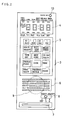
- FIGURE 2 is an enlarged front view of the operation panel 3 of the heating apparatus of FIGURE 1.
- the display part 4 comprises a numeric display means for diaplaying figures of four orders with 7-display-segments, a colon display means, and a status display means for displaying program status corresponding to key input data.
- the key board 5 is provided with 16 keys including several setting keys to input such sequence programs as shown in FIGURE 2, and a reset key to cancel their input data.
- the operation panel 3 is further provided with a timer setting key 10 and a sound level select knob 8 used for changing sound level of the synthesized voice from the heating apparatus embodying the present invention.
- a plurality of opening slots 6 are formed for a speaker 9 disposed on the rear side of the operation panel 3.
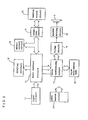
- FIGURE 3 is a block diagram of whole control circuits used in the heating apparatus embodying the present invention.
- An input circuit 11 is constituted by the key board 5 and the reset button 10 shown in FIGURE 2.
- a display circuit 12 is used for controlling display states by the display part 4.
- a main control circuit 13 electrically controlls all circuit operations by an MPU (micro-processing unit) contained therein.
- a sensor-control circuit 14 controls a sensor operation for detecting heating states of the heating foods.
- An interface circuit 15 is used to send control signals from the main control circuit 13 to a heating source circuit 16.
- the whole circuits of FIGURE 3 further comprises a voice synthesizing circuit 17, a voice data memory 18, a filter circuit 19, a speaker driving circuit 20 for driving a speaker 9, and a power source circuit 21.
- TMS-1670 chip comprises a ROM (read only memory) of 4K bytes, a RAM (random access memory) of 512 bits, eight input port lines, sixteen individually-settable output port lines, eight parallel-settable output port lines, an ALU (arithmetic logic unit), an instruction PLA (programmable logic array), a program counter, a clock generator, an output PLA (programmable logic array), and several registers.
- the MPU carries out logic operations under the control of control programs stored in the 4K bytes ROM, and control operations are determined by conditions of input signals given to its input port lines.
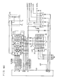
- FIGURE 4(a) is a circuit diagram of a power supply circuit and a heating source used in the heating apparatus embodying the present invention.
- the circuit part corresponding to the power source circuit 21 in. FIGURE 3 comprises a plug 41 used for establishing electric supply from a commercial power source line, a door switch 42 interlocked with the user's opening and closing operations of the door 2, a power relay 44, a fan motor 45 for cooling, and a high tension transformer 46.
- the circuit part corresponding to the heating source circuit 16 comprises a high tension capacitor 48, a high tension diode 49, a high tension relay 50, and a magnetron 51.
- a power relay driving circuit 37 energizes the power relay 44 by a PLY signal from the main control circuit 13 when the heating operation is started.
- a door-opening-state detection circuit 38 detects the opening and closing states of the door 2 when the power relay 44 is energized.
- An output signal "DOOR”, which indicates that the door is now open, is issued from the door-opening-state detection circuit 38, upon it turning its signal level from H(high level) to L(low level), when an electric motive force is generated from a winding 47 of the high 'tension transformer 46 to the door-opening-state detection circuit 38.
- a high tension relay driving circuit 39 is used for controlling high frequency power output following a duty cycle determined by heating operation programs which can be set by pushing operation keys.
- a high tension relay driving circuit 40 sends an electric power from the winding 47 of the high tension transformer 46 to energize a high tension relay 50.
- FIGURE 4(b) is a circuit diagram of another power source circuit 21 and a ripple damping circuit 23 used in the heating apparatus embodying the present invention.
- Lines with symbols F 1 and F 2 are connected to filaments of luminescent display tubes in the display circuit 12 disposed at a display board 4a (shown in FIGURE 4(c)).
- a line with symbol +B l supplies an unstabilized power voltage for driving the power relay 44.
- a stabilized voltage across lines with symbols +15V and GND is supplied to peripheral digital circuits accompanied with the main control circuit 13 including an MPU.
- FIGURE 4(e) A further stabilized voltage across lines with symbols +15V and +4V obtained by further stabilizing the stabilized voltage across the lines with symbols +15V and GND, is supplied to the main control circuit 13, a voice synthesizing circuit 17 and a voice data memory 18 (shown in FIGURE 4(e)).
- a voltage across lines with symbols +15V and -15V is supplied to the sensor control circuit 14, the filter circuit 19, the speaker driving circuit 20 and the fluorescent display tubes of the display circuit 12.
- An output signal CP from the ripple damping circuit 23 is supplied to an input port terminal K8 of the main control circuit 13 for a time base of a timer.
- FIGURE 4(c) is a circuit diagram corresponding to the input circuit 11 and the display apparatus circuit 12 shown in FIGURE 3 and used in the heating apparatus embodying the present invention.
- Input signals from the input keys disposed on the key board 5 and the reset key 10 are encoded by an encoder 22 synchronized with scanning signals issued from output port terminals R0, Rl and R2 of the main control circuit 13, and then are sent to input port terminals Kl, K2 and K4 of the main control circuit 13.
- a switch 8a is used to control sound generation. When the switch 8a is closed,'the scanning signal from the output port terminal R3 is sent to the input port terminal K2.
- a circuit 26 is a filament circuit for the fluorescent display tubes 4a.
- the fluorescent display tubes 4a comprises 6 grid electrodes Gl to G6 corresponding to four figures (Gl, G2, G4 and G5).
- the display tubes 4a dinamically light up under a control of the scanning signals from the output port terminals RO to R4.
- the scanning signal from the output port terminal R4 is applied to both grid electrodes G3 and G6.
- FIGURE 4(d) is a circuit diagram of a sensor-control circuit 14 used in the heating apparatus embodying the present invention.
- a humidity sensor 28 is used for detecting moisture exerted from the heating foods.
- a temperature sensor 29 called meat probe is used for detecting the temperature inside the foods by sticking the probe into them before starting the heating operation.
- the sensor-control circuit 14 further comprises a sampling circuit 31 for sampling humidity levels, a sampling circuit 35 for sampling temperature levels, comparators 32 and 36 constituting a simplified D/A conversion system circuit together with a 5-bit D/A converter 30, and a driving circuit 34 used for a heater 33 of the humidity sensor 28, and a circuit 27 including an oscillation circuit and an initial reset circuit for the main control circuit 13.
- the heater 33 is power-supplied from the winding 47 of the high tension transformer 46 (shown in FIGURE 4(a)).
- the temperature sensor 29 can be disposed in or removed from the heating chamber.
- the temperature levels are detected by the D/A conversion system circuit, and thereby it is automatically checked by the main control circuit 13 whether the temperature sensor 29 is used in the heating chamber. This checking is made by a fact that a sufficiently low temperature level is detected when the temperature sensor 29 is removed.
- FIGURE 4(e) is a circuit diagram of a voice synthesizing circuit used in the heating apparatus embodying the present invention.
- Data signals are sent from the main control circuit 13 to the voice synthesizing circuit 17 through data signal lines with symbols Dl to D4.
- a syncronization signal "STR" from an output port terminal R7 of the main control circuit 13 is sent to the voice synthesizing circuit 17 when the voice synthesizing operation is instructed.
- a BUSY signal is issued from the voice synthesizing circuit 17.
- the voice synthesizing circuit 17 takes out necessary voice synthesizing data from a voice data memory 18, and issues a step-shaped synthesized voice signal corresponding to the taken-out data from output terminals V 1 and V 2 of the voice synthesizing circuit 17.
- Circuits shown in FIGURE 4(e) further comprises a differential amplifier circuit 52, a filter circuit 19 and a speaker driving circuit 20.
- the filter circuit 19 and the speaker driving circuit 20 constitutes a filter-drive system circuit wherein a power booster consisting of a pair of transistors Ql and Q2 is connected to an output terminal of an operational amplifier A 2 in the filter circuit 19 and output signals of the power booster is fed back to an input terminal of the operational amplifier A 2 .
- a switch 8b is used to connect or disconnect a resistor 53 to a speaker 9 in series thereby changing volume of the synthesized voice.
- FIGURE 5 is a graph showing waveforms of several parts of the voice synthesizing circuit 17 shown in FIGURE 4(e).
- Signal waveforms V 1 and V 2 correspond to synthesized voice signals coming out from the voice synthesizing circuit 17.
- a signal waveform V 3 corresponds to an output signal of the differential amplifier 52.
- a signal waveform V 4 corresponds to an output signal of the speaker driving circuit 20.
- the ROM in the main control circuit 13, i.e. MPU chip stores the following control programs used for the heating apparatus embodying the present invention.
- the heating apparatus embodying the present invention is provided with the MPU with the above-outlined control programs stored in its ROM areas.
- each key on the key board 5 is explained below.
- Four keys “10 MIN”, “1 MIN”, “10 SEC” and “1 SEC” are time setting keys for setting time length and timings for timer for constituting the heating sequence. These four numeral keys respectively correspond to respective figures of numeral indicator in the display part 4, and setting times of each figure are increased by the same indicated time length, namely is doubled, triplicated and so on by each additional tapping of these keys.
- a "POWER SELECT" key is for selecting the microwave output power levels, and five different power levels, for example, can be selected by tapping this key.
- a "WARM/TEMP HOLD" key is for setting a "WARM” function, which is for heating the heating object for a preset time period by a power level suitable for WARM program when operating the apparatus without the temperature sensor,i.e. meat probe, and for setting a "TEMP HOLD” function, which is for moderately heating the heating object for a preset time period keeping a preset temperature by utilizing a detection signal of the temperature sensor (meat probe) inserted in the food to detect the temperature.
- the "DELAY/STAND” key is for setting a “DELAY” function, which is for prolonging the heating even after the preset period come to its end, by pushing it before the starting of the heating sequence, and for setting a “STAND” function, which is for leaving the heating object without heating for a preset time period after the heating sequence,by pushing it after the heating sequence operation.
- a “TIME DEF” key is used for defrosting an ordinary frozen food and is for setting a function which is to heat the heating object for a preset period at a power level corresponding to defrosting program, and then to leave it for the same time period thereafter.
- "BEEF PORK” key and "GP,D. MEAT POULTRY” key are used for defrosting the respective frozen foods.
- a “FROZEN FOODS” key is for setting an automatic heating which is to cook the frozen food by means of a control system using a humidity sensor, and various kinds of cooking can be selected by sequential tapping of this key.
- a “COOK” key is for setting another kind of automatic heating which is to cook food of a room temperature by means of the control system using the humidity sensor, and various kinds of cooking can be selected by tapping this key.
- a “TEMP” key is used for automatic heating by means of a temperature control of foods using a temperature sensor (meat probe), and various kinds of cooking can be selected by tapping this key.
- a “HOLD /RESET” key is for setting a “HOLD” function which stops the operation of the heating source 16 when it is in operation, and is for setting a “RESET” function which resets the stored program when it is out of operation.
- a “PROGRAM RECALL” key is used for recalling and confirming the stored program of heating sequence.
- a “START” key is for starting the heating operation of the heating source 16 by the preset heating sequence.
- a control program is preliminarily stored in a manner that a key input is judged whether it is available or not, and then a voice corresponding to the key input is synthesized only when the input is available.
- the "POWER SELECT", "DELAY/STAND” and "TIME DEF” keys are function keys for setting heating sequence by time control, and therefore time setting by four numeral keys is necessarily required as a proceeding procedure for setting heating sequence.
- the microprocessor 13 detects such vain input and does not feed a control signal for synthesizing the corresponding voice to the voice synthesizer 17. Unless the apparatus includes such measure, voices are produced whenever any of the keys are pushed and it may cause program error of the heating sequence.
- the keying input is not input into the circuit of the apparatus during voice synthesizing by the control program. Unless the apparatus includes such measure, keying input operation may sometimes interrupts a voice synthesizing and produce another newly synthesized voice which takes over interrupting the former voice, and the voice lose appropriate meaning, and it may cause a maloperations.
- the information by the "HOLD/RESET" key can be input whenever the key is pushed, because this key should be used even at an emergency.
- the "POWER SELECT”, "FROZEN FOODS”, “COOK” and “TEMP” keys have a function to be switched by tappings, and the contents of inputting are sequentially changed by tapping the keys.
- a beep sound "Pi” is produced and follows a synthesized voice corresponding to the respective keys in order to inform the inputting data from the respective keys to the user.
- only a single beep sound is produced without repeating synthesized voice for every tapping operation, thereby enabling quick tapping operation. If the same voices as that of the first tapping are repeatedly produced for every tapping, the tapping operation becomes very slow in order to wait every ending of the voices and takes much time to set the desired heating sequence when the sequence requires sequential tapping.
- the meat probe 29 In case the heating sequence with detecting the temperature of the food by the meat probe 29 is set by the "TEMP" key etc., the meat probe must be provided in the heating chamber., On the contrary, when the heating sequence without the meat probe is selected, the meat probe 29 must be removed from the heating chamber in order to protect it from exposure to the microwave radiation. Therefore, in the present invention, a measure for detection that the meat probe is set in the chamber is provided for protecting the meat probe. That is, when the user pushes a key for the sequence of setting a heating without use of the meat probe, such as "COOK" key with leaving the meat probe 29 set in the chamber, the apparatus produces a voice "Remove probe.” in order to call the user's attention to remove it.
- a volume adjusting means consisting of the volume adjusting switch 8 and the resistor 53 is provided across the speaker driving circuit 20 and the speaker 9, that is in the last stage of the electric circuit, so that the voice information is not much influen- c e d by internal electric noises peculiar to the microwave oven.
- such mixed noises are effectively reduced by connecting the volume adjusting means at a very low impedance part at the last stace part, for example, the output terminal of the speaker driving circuit 20.
- Both the voice-off switch 8a and the volume adjuring switch 8b are interconnected to the voice selection knob 8, and these switches are connected with respect to the positions of the voice selection knob 8 as shown in the following table.
- power supply is classified into two types, one of which is for the speaker driving circuit 20, wherein temporary lowering of the output voltage and temporary rising of ripple damping factor are allowed when driving the speaker, and the other is the power source for the data processing circuits such as the microprocessor 13, the voice synthesizer 17, and the ROM for voice data 18, which are very sensitive to voltage change and noises.
- the voltage to be impressed to the former circuit is selected higher than that of the latter one (data processing circuit), and the power of the latter is obtained from the output of the former one. Therefore, even when the output voltage of the former becomes somewhat lower or includes changing of the ripple damping factor when the speaker is driven, the latter voltage is kept accurately to the predetermined voltage.
- the power supply circuit is simplified and economical. This is advantageous over the conventional power source system where circuits of the former and the latter are separately structured.
Abstract
Description
- The present invention relates to a heating apparatus such as a microwave oven, more particularly to a heating apparatus which is provided with a speech synthesizer and a microcomputer.
- Recently, on the market it has become available microwave ovens which are provided with a microcomputer and are capable of programing the most suitable heating sequence among several memorized heating sequence programs during their heating operations. Generally speaking, in operating such microwave ovens the user can input data such as heating temperature, heating power output, heating time, etc. for heating sequence programs into memory devices by pushing several operation buttons with a predetermined order. By combining such button-pushing operations in complexed ways, the user can put in comparatively complicated sequence programs in the heating operations. It is naturally advantageous that by use of much complex heating sequence programs, much more different cooking methods can be employed by the users. However, there arise shortcomings that the user becomes bothered with complicated key operations and that she or he can not utilize full advantages of the heating apparatus equipped with the microcomputer.
- In particular, it is necessary to confirm whether the user's key operation is right by the displayed contents corresponding to the key input data, and therefore it takes much time to set the heating apparatus to the desired sequence program states. There is a high probability that the user erroneously inputs the sequence program data. This erroneous setting in the heating apparatus such as microwave ovens sometimes causes over-heating of the foods placed in the heating chamber, i.e. fatal cooking failure on the user side. In worst cases, such over-heating may cause burning of the user's hands and may set fire in the heating chamber. It may preferable to improve the conventional heating apparatuses in these aspects.
- On the other hand, semiconductor technology and information processing technology have much progressed and now realized that voice synthesizing is available by using one or a few LSI (large scale integrated circuit) chips. Such LSI chips can produce synthesized voices for a few minutes, and besides their costs have been lowered so that they become applicable for several kinds of home appliances.
- The present invention provides a heating apparatus such as microwave ovens equipped with a voice synthesizing circuit for easy operations with the help of the synthesized voices produced in the heating apparatus. The heating apparatus embodying the present invention can largely avert the conventional maloperation problems.
- The heating apparatus embodying the present invention can perform the following features.
- (1) Key input data can be confirmed by the synthesized voices when the operation buttons are pushed or tapped in predetermined appropriate orders;
- (2) First key input can be confirmed by the synthesized voices when the operation buttons are successively tapped, and following key input can be confirmed only by the synthesized beep sounds;
- (3) When operation keys are pushed, the corresponding input data can be confirmed by the corresponding synthesized voices, and at this moment key inputs other than from the reset key are not processed by a main control circuit;
- (4) Key input operations can be confirmed by any combination of the synthesized voices and the beep sounds;
- (5) When the user erroneously starts the heating operation by placing a meat probe inside the heating chamber, he is warned by the corresponding instruction voices thereby averting maloperations;
- (6) A built-in sound circuit is provided with a volume control means and is less sensitive to the noises; and
- (7) A much stabilized power source is employed for the digital signal circuits such as the main control circuit including the MPU and the voice synthesizing circuit, thus the heating operations are not affected even when the voltage from a power source for a speaker driving circuit is affected by driving a speaker.
-
- FIGURE 1 is a perspective view of a heating apparatus embodying the present invention.
- FIGURE 2 is a front view of an operation panel of the heating apparatus of FIGURE 1.
- FIGURE 3 is a block diagram of whole control circuits used in the heating apparatus embodying the present invention.
- FIGURE 4(a) is a circuit diagram of a power source circuit and a heating source used in the heating apparatus embodying the present invention.
- FIGURE 4(b) is a circuit diagram of another power source circuit and a ripple damping circuit used in the heating apparatus embodying the present invention.
- FIGURE 4(c) is a circuit diagram of a display apparatus circuit used in the heating apparatus embodying the present invention.
- FIGURE 4(d) is a circuit diagram of a sensor-control circuit used in the heating apparatus embodying the present invention.
- FIGURE 4(e) is a circuit diagram of a voice synthesizing circuit used in the heating apparatus embodying the present invention.
- FIGURE 5 is a graph showing waveforms of several parts of the voice synthesizing circuit used in the heating apparatus embodying the present invention.
- The present invention provides a heating apparatus comprising
- an enclosure case having therein a heating chamber in which a heating object is to be placed, the enclosure case having a door at an opening of the heating chamber,
- a heating means for generating heating energy in the heating chamber,
- a plurality of operation buttons interconnected with a key input means for inputting predetermined heating sequence data,
- a memory means for storing synthesizing voice data corresponding to predetermined heating sequence data,
- a voice synthesizing circuit for producing synthesized voices by the synthesizing voice data stored in the memory means following predetermined orders, and
- a control circuit means for controlling a heating operation of the heating means following predetermined sequence orders when heating sequence data are given thereto through the key input means.
- FIGURE 1 is a perspective view of a heating apparatus embodying the present invention. A
microwave oven case 1 comprises adoor 2, which is hinged in front thereof and has a transparent window, through which foods placed inside a heating chamber can be seen. Anoperation panel 3 is provided at and attached to the front face of theheating apparatus case 1. Theoperation panel 3 is provided with a display part 4 used for displaying numerical data and several cooking modes. Theoperation panel 3 is further provided with akey board 5 for setting heating sequence programs _and_with aspeaker 6 in the rear of theoperation panel 3. Thedoor 2 is provided with alever 7 for opening it. - FIGURE 2 is an enlarged front view of the
operation panel 3 of the heating apparatus of FIGURE 1. The display part 4 comprises a numeric display means for diaplaying figures of four orders with 7-display-segments, a colon display means, and a status display means for displaying program status corresponding to key input data. Thekey board 5 is provided with 16 keys including several setting keys to input such sequence programs as shown in FIGURE 2, and a reset key to cancel their input data. Theoperation panel 3 is further provided with atimer setting key 10 and a sound levelselect knob 8 used for changing sound level of the synthesized voice from the heating apparatus embodying the present invention. A plurality ofopening slots 6 are formed for aspeaker 9 disposed on the rear side of theoperation panel 3. - FIGURE 3 is a block diagram of whole control circuits used in the heating apparatus embodying the present invention. An
input circuit 11 is constituted by thekey board 5 and thereset button 10 shown in FIGURE 2. Adisplay circuit 12 is used for controlling display states by the display part 4. Amain control circuit 13 electrically controlls all circuit operations by an MPU (micro-processing unit) contained therein. A sensor-control circuit 14 controls a sensor operation for detecting heating states of the heating foods. Aninterface circuit 15 is used to send control signals from themain control circuit 13 to aheating source circuit 16. The whole circuits of FIGURE 3 further comprises avoice synthesizing circuit 17, avoice data memory 18, afilter circuit 19, aspeaker driving circuit 20 for driving aspeaker 9, and apower source circuit 21. - In the embodyment of the present invention a micro-processing unit (MPU) of TMS-1670 produced by Texas Instruments Inc. is employed for the
main control circuit 13. The operations of the MPU are known and hence not described here. TMS-1670 chip comprises a ROM (read only memory) of 4K bytes, a RAM (random access memory) of 512 bits, eight input port lines, sixteen individually-settable output port lines, eight parallel-settable output port lines, an ALU (arithmetic logic unit), an instruction PLA (programmable logic array), a program counter, a clock generator, an output PLA (programmable logic array), and several registers. The MPU carries out logic operations under the control of control programs stored in the 4K bytes ROM, and control operations are determined by conditions of input signals given to its input port lines. - FIGURE 4(a) is a circuit diagram of a power supply circuit and a heating source used in the heating apparatus embodying the present invention. The circuit part corresponding to the
power source circuit 21 in. FIGURE 3 comprises aplug 41 used for establishing electric supply from a commercial power source line, adoor switch 42 interlocked with the user's opening and closing operations of thedoor 2, a power relay 44, afan motor 45 for cooling, and ahigh tension transformer 46. The circuit part corresponding to theheating source circuit 16 comprises a high tension capacitor 48, a high tension diode 49, ahigh tension relay 50, and amagnetron 51. - A power
relay driving circuit 37 energizes the power relay 44 by a PLY signal from themain control circuit 13 when the heating operation is started. A door-opening-state detection circuit 38 detects the opening and closing states of thedoor 2 when the power relay 44 is energized. An output signal "DOOR", which indicates that the door is now open, is issued from the door-opening-state detection circuit 38, upon it turning its signal level from H(high level) to L(low level), when an electric motive force is generated from a winding 47 of the high 'tension transformer 46 to the door-opening-state detection circuit 38. A high tensionrelay driving circuit 39 is used for controlling high frequency power output following a duty cycle determined by heating operation programs which can be set by pushing operation keys. A high tensionrelay driving circuit 40 sends an electric power from the winding 47 of thehigh tension transformer 46 to energize ahigh tension relay 50. - FIGURE 4(b) is a circuit diagram of another
power source circuit 21 and aripple damping circuit 23 used in the heating apparatus embodying the present invention. Lines with symbols F1 and F2 are connected to filaments of luminescent display tubes in thedisplay circuit 12 disposed at a display board 4a (shown in FIGURE 4(c)). A line with symbol +Bl supplies an unstabilized power voltage for driving the power relay 44. A stabilized voltage across lines with symbols +15V and GND is supplied to peripheral digital circuits accompanied with themain control circuit 13 including an MPU. A further stabilized voltage across lines with symbols +15V and +4V obtained by further stabilizing the stabilized voltage across the lines with symbols +15V and GND, is supplied to themain control circuit 13, avoice synthesizing circuit 17 and a voice data memory 18 (shown in FIGURE 4(e)). A voltage across lines with symbols +15V and -15V is supplied to thesensor control circuit 14, thefilter circuit 19, thespeaker driving circuit 20 and the fluorescent display tubes of thedisplay circuit 12. An output signal CP from theripple damping circuit 23 is supplied to an input port terminal K8 of themain control circuit 13 for a time base of a timer. FIGURE 4(c) is a circuit diagram corresponding to theinput circuit 11 and thedisplay apparatus circuit 12 shown in FIGURE 3 and used in the heating apparatus embodying the present invention. Input signals from the input keys disposed on thekey board 5 and the reset key 10 are encoded by anencoder 22 synchronized with scanning signals issued from output port terminals R0, Rl and R2 of themain control circuit 13, and then are sent to input port terminals Kl, K2 and K4 of themain control circuit 13. A switch 8a is used to control sound generation. When the switch 8a is closed,'the scanning signal from the output port terminal R3 is sent to the input port terminal K2. - Signals "BUSY", "DOOR", "TEMP" and "HUM" as shown at lines with corresponding symbols on FIGURE 4(c) are sent to input port terminals Kl, K2 and K4, with timings synchronized with the scanning signals from output port terminals R3 and R4. A
circuit 26 is a filament circuit for the fluorescent display tubes 4a. The fluorescent display tubes 4a comprises 6 grid electrodes Gl to G6 corresponding to four figures (Gl, G2, G4 and G5). The display tubes 4a dinamically light up under a control of the scanning signals from the output port terminals RO to R4. The scanning signal from the output port terminal R4 is applied to both grid electrodes G3 and G6. - FIGURE 4(d) is a circuit diagram of a sensor-
control circuit 14 used in the heating apparatus embodying the present invention. Ahumidity sensor 28 is used for detecting moisture exerted from the heating foods. Atemperature sensor 29 called meat probe is used for detecting the temperature inside the foods by sticking the probe into them before starting the heating operation. - The sensor-
control circuit 14 further comprises asampling circuit 31 for sampling humidity levels, asampling circuit 35 for sampling temperature levels,comparators A converter 30, and a driving circuit 34 used for aheater 33 of thehumidity sensor 28, and acircuit 27 including an oscillation circuit and an initial reset circuit for themain control circuit 13. Theheater 33 is power-supplied from the winding 47 of the high tension transformer 46 (shown in FIGURE 4(a)). - The
temperature sensor 29 can be disposed in or removed from the heating chamber. The temperature levels are detected by the D/A conversion system circuit, and thereby it is automatically checked by themain control circuit 13 whether thetemperature sensor 29 is used in the heating chamber. This checking is made by a fact that a sufficiently low temperature level is detected when thetemperature sensor 29 is removed. - FIGURE 4(e) is a circuit diagram of a voice synthesizing circuit used in the heating apparatus embodying the present invention. Data signals are sent from the
main control circuit 13 to thevoice synthesizing circuit 17 through data signal lines with symbols Dl to D4. A syncronization signal "STR" from an output port terminal R7 of themain control circuit 13 is sent to thevoice synthesizing circuit 17 when the voice synthesizing operation is instructed. When thevoice synthesizing circuit 17 is in operation, i.e. when it produces synthesized voices, a BUSY signal is issued from thevoice synthesizing circuit 17. Once thevoice synthesizing circuit 17 is instructed to be set in operation, it takes out necessary voice synthesizing data from avoice data memory 18, and issues a step-shaped synthesized voice signal corresponding to the taken-out data from output terminals V1 and V2 of thevoice synthesizing circuit 17. - Circuits shown in FIGURE 4(e) further comprises a
differential amplifier circuit 52, afilter circuit 19 and aspeaker driving circuit 20. Thefilter circuit 19 and thespeaker driving circuit 20 constitutes a filter-drive system circuit wherein a power booster consisting of a pair of transistors Ql and Q2 is connected to an output terminal of an operational amplifier A2 in thefilter circuit 19 and output signals of the power booster is fed back to an input terminal of the operational amplifier A2. Aswitch 8b is used to connect or disconnect aresistor 53 to aspeaker 9 in series thereby changing volume of the synthesized voice. - FIGURE 5 is a graph showing waveforms of several parts of the
voice synthesizing circuit 17 shown in FIGURE 4(e). Signal waveforms V1 and V2 correspond to synthesized voice signals coming out from thevoice synthesizing circuit 17. A signal waveform V3 corresponds to an output signal of thedifferential amplifier 52. A signal waveform V4 corresponds to an output signal of thespeaker driving circuit 20. - The ROM in the
main control circuit 13, i.e. MPU chip stores the following control programs used for the heating apparatus embodying the present invention. - i) Key input processing program, by which key input is detected, then it is checked whether the key input is appropriate at the input time before, during, or after the heating operation, and following the check the key input is processed in case that it is right;
- ii) A tapping number counting program for counting how many times the same input keys are tapped (when the same input keys are successively tapped, input data are successively renewed), and for checking which input keys are tapped in which orders;
- iii) A checking program for checking the use of the temperature sensor, i.e. meat probe by detecting the temperature signal level;
- iv) A memory control program for storing key input data;
- v) A count-down timer program for successively carrying out heat sequence programs corresponding to key input data;
- vi) A control program for controlling the display circuit;
- vii) A sensor-control program for controlling the sensor circuit;
- viii) A control program for controlling the function of the voice synthesizing circuit; and
- iv) A timer program for producing a time base for heating sequence periods..
- The heating apparatus embodying the present invention is provided with the MPU with the above-outlined control programs stored in its ROM areas.
- The functions of each key on the
key board 5 are explained below. Four keys "10 MIN", "1 MIN", "10 SEC" and "1 SEC" are time setting keys for setting time length and timings for timer for constituting the heating sequence. These four numeral keys respectively correspond to respective figures of numeral indicator in the display part 4, and setting times of each figure are increased by the same indicated time length, namely is doubled, triplicated and so on by each additional tapping of these keys. A "POWER SELECT" key is for selecting the microwave output power levels, and five different power levels, for example, can be selected by tapping this key. A "WARM/TEMP HOLD" key is for setting a "WARM" function, which is for heating the heating object for a preset time period by a power level suitable for WARM program when operating the apparatus without the temperature sensor,i.e. meat probe, and for setting a "TEMP HOLD" function, which is for moderately heating the heating object for a preset time period keeping a preset temperature by utilizing a detection signal of the temperature sensor (meat probe) inserted in the food to detect the temperature. The "DELAY/STAND" key is for setting a "DELAY" function, which is for prolonging the heating even after the preset period come to its end, by pushing it before the starting of the heating sequence, and for setting a "STAND" function, which is for leaving the heating object without heating for a preset time period after the heating sequence,by pushing it after the heating sequence operation. A "TIME DEF" key is used for defrosting an ordinary frozen food and is for setting a function which is to heat the heating object for a preset period at a power level corresponding to defrosting program, and then to leave it for the same time period thereafter. "BEEF PORK" key and "GP,D. MEAT POULTRY" key are used for defrosting the respective frozen foods. A "FROZEN FOODS" key is for setting an automatic heating which is to cook the frozen food by means of a control system using a humidity sensor, and various kinds of cooking can be selected by sequential tapping of this key. A "COOK" key is for setting another kind of automatic heating which is to cook food of a room temperature by means of the control system using the humidity sensor, and various kinds of cooking can be selected by tapping this key. A "TEMP" key is used for automatic heating by means of a temperature control of foods using a temperature sensor (meat probe), and various kinds of cooking can be selected by tapping this key. A "HOLD /RESET" key is for setting a "HOLD" function which stops the operation of theheating source 16 when it is in operation, and is for setting a "RESET" function which resets the stored program when it is out of operation. A "PROGRAM RECALL" key is used for recalling and confirming the stored program of heating sequence. And a "START" key is for starting the heating operation of theheating source 16 by the preset heating sequence. - The operation of this embodiment is explained below. At first, in the present invention, a control program is preliminarily stored in a manner that a key input is judged whether it is available or not, and then a voice corresponding to the key input is synthesized only when the input is available. For example, the "POWER SELECT", "DELAY/STAND" and "TIME DEF" keys are function keys for setting heating sequence by time control, and therefore time setting by four numeral keys is necessarily required as a proceeding procedure for setting heating sequence. At this time, if the user pushes any keys except the time setting keys or the "RESET" key, the
microprocessor 13 detects such vain input and does not feed a control signal for synthesizing the corresponding voice to thevoice synthesizer 17. Unless the apparatus includes such measure, voices are produced whenever any of the keys are pushed and it may cause program error of the heating sequence. - Furthermore, in the present invention, the keying input is not input into the circuit of the apparatus during voice synthesizing by the control program. Unless the apparatus includes such measure, keying input operation may sometimes interrupts a voice synthesizing and produce another newly synthesized voice which takes over interrupting the former voice, and the voice lose appropriate meaning, and it may cause a maloperations. However, the information by the "HOLD/RESET" key can be input whenever the key is pushed, because this key should be used even at an emergency.
- The "POWER SELECT", "FROZEN FOODS", "COOK" and "TEMP" keys have a function to be switched by tappings, and the contents of inputting are sequentially changed by tapping the keys. As shown in the following list, at a first tapping input, a beep sound "Pi" is produced and follows a synthesized voice corresponding to the respective keys in order to inform the inputting data from the respective keys to the user. And after the second tapping, only a single beep sound is produced without repeating synthesized voice for every tapping operation, thereby enabling quick tapping operation. If the same voices as that of the first tapping are repeatedly produced for every tapping, the tapping operation becomes very slow in order to wait every ending of the voices and takes much time to set the desired heating sequence when the sequence requires sequential tapping.

- In the present invention, distinction is made between the first tapping or the second tapping and thereafter from each other and respective voice and beep sound are synthesized in the
voice synthesizer 17 with respect to the number of tapping. - In case the heating sequence with detecting the temperature of the food by the
meat probe 29 is set by the "TEMP" key etc., the meat probe must be provided in the heating chamber., On the contrary, when the heating sequence without the meat probe is selected, themeat probe 29 must be removed from the heating chamber in order to protect it from exposure to the microwave radiation. Therefore, in the present invention, a measure for detection that the meat probe is set in the chamber is provided for protecting the meat probe. That is, when the user pushes a key for the sequence of setting a heating without use of the meat probe, such as "COOK" key with leaving themeat probe 29 set in the chamber, the apparatus produces a voice "Remove probe." in order to call the user's attention to remove it. On the contrary, when, under the condition that the meat probe is removed, the user pushes the "TEMP" key for setting the heating sequence which necessitates the meat probe, the apparatus produces "Insert probe." in order to call the user's attention. By means of the abovementioned measures the users correctly use the heating sequence by the abovementioned voice information. But once she becomes well skilled in the use of the heating apparatus, such voice informations are no more necessary to him or her and further, such may become even offensive to him or her. Therefore, in the present invention, only the beep sound "Pi" can also be produced without synthesizing the voice by the "Voice-off" switch 8a. - Furthermore, in the present invention, a volume adjusting means consisting of the
volume adjusting switch 8 and theresistor 53 is provided across thespeaker driving circuit 20 and thespeaker 9, that is in the last stage of the electric circuit, so that the voice information is not much influen- ced by internal electric noises peculiar to the microwave oven. Generally speaking, there are high intensity electric noises radiated from the magnetron inside the heating chamber, and accordingly such noises may be mixed in the voice synthesizing circuit through a lead wire for thevolume adjusting switch 8b. In the present invention, such mixed noises are effectively reduced by connecting the volume adjusting means at a very low impedance part at the last stace part, for example, the output terminal of thespeaker driving circuit 20. Both the voice-off switch 8a and thevolume adjuring switch 8b are interconnected to thevoice selection knob 8, and these switches are connected with respect to the positions of thevoice selection knob 8 as shown in the following table.
- Next, the construction concerning a power supply is mentioned below.
- In the present invention, power supply is classified into two types, one of which is for the
speaker driving circuit 20, wherein temporary lowering of the output voltage and temporary rising of ripple damping factor are allowed when driving the speaker, and the other is the power source for the data processing circuits such as themicroprocessor 13, thevoice synthesizer 17, and the ROM forvoice data 18, which are very sensitive to voltage change and noises. In the present invention, the voltage to be impressed to the former circuit (speaker driving circuit) is selected higher than that of the latter one (data processing circuit), and the power of the latter is obtained from the output of the former one. Therefore, even when the output voltage of the former becomes somewhat lower or includes changing of the ripple damping factor when the speaker is driven, the latter voltage is kept accurately to the predetermined voltage. In addition, the power supply circuit is simplified and economical. This is advantageous over the conventional power source system where circuits of the former and the latter are separately structured.
Claims (10)
Applications Claiming Priority (4)
| Application Number | Priority Date | Filing Date | Title |
|---|---|---|---|
| JP172044/79 | 1979-12-26 | ||
| JP17204479A JPS5692603A (en) | 1979-12-26 | 1979-12-26 | High frequency heater |
| JP7043580A JPS56166505A (en) | 1980-05-26 | 1980-05-26 | High frequency heater |
| JP70435/80 | 1980-05-26 |
Publications (3)
| Publication Number | Publication Date |
|---|---|
| EP0031589A2 true EP0031589A2 (en) | 1981-07-08 |
| EP0031589A3 EP0031589A3 (en) | 1981-11-25 |
| EP0031589B1 EP0031589B1 (en) | 1986-11-12 |
Family
ID=26411592
Family Applications (1)
| Application Number | Title | Priority Date | Filing Date |
|---|---|---|---|
| EP80108174A Expired EP0031589B1 (en) | 1979-12-26 | 1980-12-23 | Food heating apparatus provided with a voice synthesizing circuit |
Country Status (5)
| Country | Link |
|---|---|
| US (1) | US4351999A (en) |
| EP (1) | EP0031589B1 (en) |
| AU (1) | AU531117B2 (en) |
| CA (1) | CA1166704A (en) |
| DE (1) | DE3071835D1 (en) |
Cited By (9)
| Publication number | Priority date | Publication date | Assignee | Title |
|---|---|---|---|---|
| EP0049364A2 (en) * | 1980-09-05 | 1982-04-14 | Bosch-Siemens HausgerÀ¤te GmbH | Arrangement for controlling heating appliances and cooking utensils |
| EP0063473A2 (en) * | 1981-04-16 | 1982-10-27 | Matsushita Electric Industrial Co., Ltd. | Control apparatus for heating appliance |
| EP0106887A1 (en) * | 1982-04-19 | 1984-05-02 | Exide Electronics International Corp. | Emergency device employing programmable vocal warning commands |
| EP0238022A2 (en) * | 1986-03-20 | 1987-09-23 | Matsushita Electric Industrial Co., Ltd. | Heating apparatus |
| EP0361586A2 (en) * | 1988-09-23 | 1990-04-04 | Ire Industrie Riunite Eurodomestici S.R.L. | Device for automatically controlling food preparation in a microwave oven |
| GB2286319A (en) * | 1994-01-12 | 1995-08-09 | Intertechnique Sa | Apparatus including computer control and voice repetition of digital setting messages |
| GB2296341A (en) * | 1994-11-26 | 1996-06-26 | Motorola Ltd | Electronic equipment with input elements and speech generator |
| EP2330867A1 (en) * | 2009-12-03 | 2011-06-08 | Electrolux Home Products Corporation N.V. | Oven and method for operating an oven |
| EP3291645A1 (en) * | 2016-08-31 | 2018-03-07 | E.G.O. ELEKTRO-GERÄTEBAU GmbH | Microwave oven |
Families Citing this family (22)
| Publication number | Priority date | Publication date | Assignee | Title |
|---|---|---|---|---|
| US4517431A (en) * | 1981-05-04 | 1985-05-14 | Matsushita Electric Industrial Co., Ltd. | Safety device for a heating appliance |
| JPS5877409A (en) * | 1981-10-30 | 1983-05-10 | Inoue Japax Res Inc | Fire prevention device for electric discharge machining unit |
| US4520576A (en) * | 1983-09-06 | 1985-06-04 | Whirlpool Corporation | Conversational voice command control system for home appliance |
| JPS60141025A (en) * | 1983-12-28 | 1985-07-26 | Toshiba Corp | Tone signal generating system in communication equipment |
| GB2186273B (en) * | 1986-02-10 | 1990-02-14 | Instance Ltd David J | A container |
| DE3788933T2 (en) * | 1986-11-13 | 1994-12-22 | Whirlpool Europ | Microwave oven. |
| CA1268228A (en) * | 1987-09-14 | 1990-04-24 | Gary Lennartz | Voice interactive security system |
| US5460228A (en) * | 1993-07-20 | 1995-10-24 | Butler; Marty | Fire extinguisher with recorded message |
| US6249710B1 (en) * | 1996-05-14 | 2001-06-19 | Microwave Science, Llc | Method and apparatus for managing the thermal activity of a microwave oven |
| JP2895033B2 (en) * | 1997-05-12 | 1999-05-24 | 三星電子株式会社 | Microwave oven inrush current prevention circuit |
| CA2347245C (en) | 1998-10-14 | 2007-10-09 | Gary J. Morris | Communicative environmental alarm system with voice indication |
| US6144310A (en) | 1999-01-26 | 2000-11-07 | Morris; Gary Jay | Environmental condition detector with audible alarm and voice identifier |
| US6768424B1 (en) | 1999-01-21 | 2004-07-27 | Gary J. Morris | Environmental condition detector with remote fire extinguisher locator system |
| DE10061821C2 (en) * | 2000-12-12 | 2002-11-28 | Rational Ag | Method for guiding a cooking process with a cooking process sensor |
| CN1251943C (en) * | 2001-06-28 | 2006-04-19 | 全秉真 | Cargo container having audio system |
| KR20040033128A (en) * | 2002-10-11 | 2004-04-21 | 삼성전자주식회사 | Method and apparatus for controlling a microwave oven |
| KR101013593B1 (en) * | 2010-01-22 | 2011-02-14 | 주식회사 오쿠 | The method of cooking which uses the automatic control type double boiler |
| US9058024B2 (en) * | 2013-01-07 | 2015-06-16 | Bsh Home Appliances Corporation | User interface—oven timer |
| US11104502B2 (en) * | 2016-03-01 | 2021-08-31 | Jeffrey S. Melcher | Multi-function compact appliance and methods for a food or item in a container with a container storage technology |
| DE102016117922A1 (en) | 2016-09-22 | 2018-03-22 | Rational Aktiengesellschaft | Method for operating a microwave source and a cooking appliance |
| US10747968B2 (en) | 2017-11-22 | 2020-08-18 | Jeffrey S. Melcher | Wireless device and selective user control and management of a wireless device and data |
| US11143414B2 (en) | 2018-11-02 | 2021-10-12 | Karen Spence | Aided safety cooking appliance |
Citations (3)
| Publication number | Priority date | Publication date | Assignee | Title |
|---|---|---|---|---|
| US3641496A (en) | 1969-06-23 | 1972-02-08 | Phonplex Corp | Electronic voice annunciating system having binary data converted into audio representations |
| US4011428A (en) | 1975-03-24 | 1977-03-08 | Essex International, Inc. | Microwave oven timer and control circuit |
| EP0027711A2 (en) | 1979-10-18 | 1981-04-29 | Matsushita Electric Industrial Co., Ltd. | Heating apparatus safety device using voice synthesizer |
Family Cites Families (10)
| Publication number | Priority date | Publication date | Assignee | Title |
|---|---|---|---|---|
| JPS5737079B2 (en) * | 1974-11-20 | 1982-08-07 | ||
| JPS52101739A (en) * | 1975-10-31 | 1977-08-26 | Toshiba Corp | Digital timer for electronic range |
| US4158432A (en) * | 1976-12-10 | 1979-06-19 | Texas Instruments Incorporated | Control of self-test feature for appliances or electronic equipment operated by microprocessor |
| JPS542098A (en) * | 1977-06-07 | 1979-01-09 | Toshiba Corp | Output system of audio alarm |
| US4162381A (en) * | 1977-08-30 | 1979-07-24 | Litton Systems, Inc. | Microwave oven sensing system |
| US4158759A (en) * | 1977-09-16 | 1979-06-19 | Teccor Electronics, Inc. | Microwave oven control system |
| US4163120A (en) * | 1978-04-06 | 1979-07-31 | Bell Telephone Laboratories, Incorporated | Voice synthesizer |
| DE2917214A1 (en) * | 1978-04-27 | 1979-11-08 | Amana Refrigeration Inc | Program control for microwave oven - has probe for setting energy dependent on condition of article in oven |
| US4230731A (en) * | 1978-05-25 | 1980-10-28 | Robertshaw Controls Company | Microwave cooking method and control means |
| EP0025513B1 (en) * | 1979-08-17 | 1984-02-15 | Matsushita Electric Industrial Co., Ltd. | Heating apparatus with sensor |
-
1980
- 1980-12-23 EP EP80108174A patent/EP0031589B1/en not_active Expired
- 1980-12-23 DE DE8080108174T patent/DE3071835D1/en not_active Expired
- 1980-12-23 US US06/220,234 patent/US4351999A/en not_active Expired - Lifetime
- 1980-12-24 AU AU65858/80A patent/AU531117B2/en not_active Ceased
- 1980-12-29 CA CA000367637A patent/CA1166704A/en not_active Expired
Patent Citations (3)
| Publication number | Priority date | Publication date | Assignee | Title |
|---|---|---|---|---|
| US3641496A (en) | 1969-06-23 | 1972-02-08 | Phonplex Corp | Electronic voice annunciating system having binary data converted into audio representations |
| US4011428A (en) | 1975-03-24 | 1977-03-08 | Essex International, Inc. | Microwave oven timer and control circuit |
| EP0027711A2 (en) | 1979-10-18 | 1981-04-29 | Matsushita Electric Industrial Co., Ltd. | Heating apparatus safety device using voice synthesizer |
Cited By (18)
| Publication number | Priority date | Publication date | Assignee | Title |
|---|---|---|---|---|
| EP0049364A2 (en) * | 1980-09-05 | 1982-04-14 | Bosch-Siemens HausgerÀ¤te GmbH | Arrangement for controlling heating appliances and cooking utensils |
| EP0049364A3 (en) * | 1980-09-05 | 1983-08-24 | Bosch-Siemens Hausgerate Gmbh Stuttgart | Arrangement for controlling heating appliances and cooking utensils |
| EP0063473A2 (en) * | 1981-04-16 | 1982-10-27 | Matsushita Electric Industrial Co., Ltd. | Control apparatus for heating appliance |
| EP0063473A3 (en) * | 1981-04-16 | 1983-09-21 | Matsushita Electric Industrial Co., Ltd. | Control apparatus for heating appliance |
| EP0106887A1 (en) * | 1982-04-19 | 1984-05-02 | Exide Electronics International Corp. | Emergency device employing programmable vocal warning commands |
| EP0106887A4 (en) * | 1982-04-19 | 1984-09-13 | Exide Electronics Internat Cor | Emergency device employing programmable vocal warning commands. |
| US4814570A (en) * | 1986-03-20 | 1989-03-21 | Matsushita Electric Industrial Co., Ltd. | Automatic heating apparatus provided with gas and weight sensors |
| EP0238022A3 (en) * | 1986-03-20 | 1988-08-24 | Matsushita Electric Industrial Co., Ltd. | Heating apparatus |
| EP0238022A2 (en) * | 1986-03-20 | 1987-09-23 | Matsushita Electric Industrial Co., Ltd. | Heating apparatus |
| EP0361586A2 (en) * | 1988-09-23 | 1990-04-04 | Ire Industrie Riunite Eurodomestici S.R.L. | Device for automatically controlling food preparation in a microwave oven |
| EP0361586A3 (en) * | 1988-09-23 | 1991-08-28 | Ire Industrie Riunite Eurodomestici S.R.L. | Device for automatically controlling food preparation in a microwave oven |
| GB2286319A (en) * | 1994-01-12 | 1995-08-09 | Intertechnique Sa | Apparatus including computer control and voice repetition of digital setting messages |
| GB2286319B (en) * | 1994-01-12 | 1998-08-12 | Intertechnique Sa | Apparatus including computer control and voice repetition of digital setting messages |
| GB2296341A (en) * | 1994-11-26 | 1996-06-26 | Motorola Ltd | Electronic equipment with input elements and speech generator |
| EP2330867A1 (en) * | 2009-12-03 | 2011-06-08 | Electrolux Home Products Corporation N.V. | Oven and method for operating an oven |
| WO2011066976A1 (en) * | 2009-12-03 | 2011-06-09 | Electrolux Home Products Corporation N.V. | Oven and method for operating an oven |
| US9055618B2 (en) | 2009-12-03 | 2015-06-09 | Electrolux Home Products Corporation N.V. | Oven and method for operating an oven |
| EP3291645A1 (en) * | 2016-08-31 | 2018-03-07 | E.G.O. ELEKTRO-GERÄTEBAU GmbH | Microwave oven |
Also Published As
| Publication number | Publication date |
|---|---|
| DE3071835D1 (en) | 1987-01-02 |
| AU6585880A (en) | 1981-07-02 |
| EP0031589A3 (en) | 1981-11-25 |
| CA1166704A (en) | 1984-05-01 |
| US4351999A (en) | 1982-09-28 |
| AU531117B2 (en) | 1983-08-11 |
| EP0031589B1 (en) | 1986-11-12 |
Similar Documents
| Publication | Publication Date | Title |
|---|---|---|
| EP0031589A2 (en) | Food heating apparatus provided with a voice synthesizing circuit | |
| US4345145A (en) | User programmable control system for toaster oven appliance | |
| US4463238A (en) | Combined microwave and electric heating oven selectively controlled by gas sensor output and thermistor output | |
| EP0550124B1 (en) | Oven controlled by an optical code reader | |
| US4390766A (en) | Apparatus and method for controlling electronic controlled cooking apparatus having storage | |
| US4356370A (en) | Apparatus for controlling electronic controlled cooking apparatus | |
| US4572935A (en) | Cooking apparatus having an initial temperature setting function | |
| JPS5916171B2 (en) | High frequency heating device | |
| US5430272A (en) | Method and apparatus for heating food | |
| KR940000313B1 (en) | Cooking-finishing sound output method for electronic range | |
| KR940000314B1 (en) | Standing time displaying method for electronic range | |
| KR100281703B1 (en) | Automatic cooking of gas oven range | |
| JP2554725B2 (en) | Heating cooker | |
| KR100276025B1 (en) | Method for guiding control order of microwave oven | |
| KR830002002B1 (en) | Microwave | |
| KR100276027B1 (en) | Method for displaying time in cooking of microwave oven | |
| JPH06237853A (en) | Rice cooker | |
| JPS631717B2 (en) | ||
| KR19990047960A (en) | How to control buzzer sound of microwave oven | |
| KR820000262Y1 (en) | Control circuit for micro-wave heating range | |
| KR100225626B1 (en) | Apparatus for inputing the cooking menu of a microwave oven | |
| CA1142232A (en) | Damper activation in a combined microwave and electric heating oven | |
| JPH10177893A (en) | Heating cooking device | |
| JPS59151794A (en) | Cooking device | |
| JPS62218733A (en) | Automatic heating and cooking device |
Legal Events
| Date | Code | Title | Description |
|---|---|---|---|
| PUAI | Public reference made under article 153(3) epc to a published international application that has entered the european phase |
Free format text: ORIGINAL CODE: 0009012 |
|
| AK | Designated contracting states |
Designated state(s): CH DE FR GB NL SE |
|
| PUAL | Search report despatched |
Free format text: ORIGINAL CODE: 0009013 |
|
| AK | Designated contracting states |
Designated state(s): CH DE FR GB NL SE |
|
| 17P | Request for examination filed |
Effective date: 19811029 |
|
| GRAA | (expected) grant |
Free format text: ORIGINAL CODE: 0009210 |
|
| AK | Designated contracting states |
Kind code of ref document: B1 Designated state(s): CH DE FR GB LI NL SE |
|
| REF | Corresponds to: |
Ref document number: 3071835 Country of ref document: DE Date of ref document: 19870102 |
|
| ET | Fr: translation filed | ||
| PLBE | No opposition filed within time limit |
Free format text: ORIGINAL CODE: 0009261 |
|
| STAA | Information on the status of an ep patent application or granted ep patent |
Free format text: STATUS: NO OPPOSITION FILED WITHIN TIME LIMIT |
|
| 26N | No opposition filed | ||
| EAL | Se: european patent in force in sweden |
Ref document number: 80108174.6 |
|
| PGFP | Annual fee paid to national office [announced via postgrant information from national office to epo] |
Ref country code: NL Payment date: 19951230 Year of fee payment: 16 |
|
| PGFP | Annual fee paid to national office [announced via postgrant information from national office to epo] |
Ref country code: CH Payment date: 19960125 Year of fee payment: 16 |
|
| REG | Reference to a national code |
Ref country code: GB Ref legal event code: 746 Effective date: 19960820 |
|
| PG25 | Lapsed in a contracting state [announced via postgrant information from national office to epo] |
Ref country code: LI Effective date: 19961231 Ref country code: CH Effective date: 19961231 |
|
| PG25 | Lapsed in a contracting state [announced via postgrant information from national office to epo] |
Ref country code: NL Effective date: 19970701 |
|
| REG | Reference to a national code |
Ref country code: CH Ref legal event code: PL |
|
| NLV4 | Nl: lapsed or anulled due to non-payment of the annual fee |
Effective date: 19970701 |
|
| PGFP | Annual fee paid to national office [announced via postgrant information from national office to epo] |
Ref country code: SE Payment date: 19981207 Year of fee payment: 19 |
|
| PGFP | Annual fee paid to national office [announced via postgrant information from national office to epo] |
Ref country code: FR Payment date: 19981209 Year of fee payment: 19 |
|
| PGFP | Annual fee paid to national office [announced via postgrant information from national office to epo] |
Ref country code: GB Payment date: 19981224 Year of fee payment: 19 |
|
| PGFP | Annual fee paid to national office [announced via postgrant information from national office to epo] |
Ref country code: DE Payment date: 19990107 Year of fee payment: 19 |
|
| PG25 | Lapsed in a contracting state [announced via postgrant information from national office to epo] |
Ref country code: GB Free format text: LAPSE BECAUSE OF NON-PAYMENT OF DUE FEES Effective date: 19991223 |
|
| PG25 | Lapsed in a contracting state [announced via postgrant information from national office to epo] |
Ref country code: SE Free format text: LAPSE BECAUSE OF NON-PAYMENT OF DUE FEES Effective date: 19991224 |
|
| EUG | Se: european patent has lapsed |
Ref document number: 80108174.6 |
|
| GBPC | Gb: european patent ceased through non-payment of renewal fee |
Effective date: 19991223 |
|
| PG25 | Lapsed in a contracting state [announced via postgrant information from national office to epo] |
Ref country code: FR Free format text: LAPSE BECAUSE OF NON-PAYMENT OF DUE FEES Effective date: 20000831 |
|
| PG25 | Lapsed in a contracting state [announced via postgrant information from national office to epo] |
Ref country code: DE Free format text: LAPSE BECAUSE OF NON-PAYMENT OF DUE FEES Effective date: 20001003 |
|
| REG | Reference to a national code |
Ref country code: FR Ref legal event code: ST |