EP0033204A2 - Suspension systems for vehicles - Google Patents
Suspension systems for vehicles Download PDFInfo
- Publication number
- EP0033204A2 EP0033204A2 EP81300168A EP81300168A EP0033204A2 EP 0033204 A2 EP0033204 A2 EP 0033204A2 EP 81300168 A EP81300168 A EP 81300168A EP 81300168 A EP81300168 A EP 81300168A EP 0033204 A2 EP0033204 A2 EP 0033204A2
- Authority
- EP
- European Patent Office
- Prior art keywords
- vehicle
- suspension
- difference
- height
- suspension system
- Prior art date
- Legal status (The legal status is an assumption and is not a legal conclusion. Google has not performed a legal analysis and makes no representation as to the accuracy of the status listed.)
- Withdrawn
Links
Images
Classifications
-
- B—PERFORMING OPERATIONS; TRANSPORTING
- B60—VEHICLES IN GENERAL
- B60G—VEHICLE SUSPENSION ARRANGEMENTS
- B60G17/00—Resilient suspensions having means for adjusting the spring or vibration-damper characteristics, for regulating the distance between a supporting surface and a sprung part of vehicle or for locking suspension during use to meet varying vehicular or surface conditions, e.g. due to speed or load
- B60G17/02—Spring characteristics, e.g. mechanical springs and mechanical adjusting means
- B60G17/04—Spring characteristics, e.g. mechanical springs and mechanical adjusting means fluid spring characteristics
- B60G17/056—Regulating distributors or valves for hydropneumatic systems
-
- B—PERFORMING OPERATIONS; TRANSPORTING
- B60—VEHICLES IN GENERAL
- B60G—VEHICLE SUSPENSION ARRANGEMENTS
- B60G17/00—Resilient suspensions having means for adjusting the spring or vibration-damper characteristics, for regulating the distance between a supporting surface and a sprung part of vehicle or for locking suspension during use to meet varying vehicular or surface conditions, e.g. due to speed or load
- B60G17/015—Resilient suspensions having means for adjusting the spring or vibration-damper characteristics, for regulating the distance between a supporting surface and a sprung part of vehicle or for locking suspension during use to meet varying vehicular or surface conditions, e.g. due to speed or load the regulating means comprising electric or electronic elements
- B60G17/016—Resilient suspensions having means for adjusting the spring or vibration-damper characteristics, for regulating the distance between a supporting surface and a sprung part of vehicle or for locking suspension during use to meet varying vehicular or surface conditions, e.g. due to speed or load the regulating means comprising electric or electronic elements characterised by their responsiveness, when the vehicle is travelling, to specific motion, a specific condition, or driver input
- B60G17/0162—Resilient suspensions having means for adjusting the spring or vibration-damper characteristics, for regulating the distance between a supporting surface and a sprung part of vehicle or for locking suspension during use to meet varying vehicular or surface conditions, e.g. due to speed or load the regulating means comprising electric or electronic elements characterised by their responsiveness, when the vehicle is travelling, to specific motion, a specific condition, or driver input mainly during a motion involving steering operation, e.g. cornering, overtaking
-
- B—PERFORMING OPERATIONS; TRANSPORTING
- B60—VEHICLES IN GENERAL
- B60G—VEHICLE SUSPENSION ARRANGEMENTS
- B60G17/00—Resilient suspensions having means for adjusting the spring or vibration-damper characteristics, for regulating the distance between a supporting surface and a sprung part of vehicle or for locking suspension during use to meet varying vehicular or surface conditions, e.g. due to speed or load
- B60G17/015—Resilient suspensions having means for adjusting the spring or vibration-damper characteristics, for regulating the distance between a supporting surface and a sprung part of vehicle or for locking suspension during use to meet varying vehicular or surface conditions, e.g. due to speed or load the regulating means comprising electric or electronic elements
- B60G17/0195—Resilient suspensions having means for adjusting the spring or vibration-damper characteristics, for regulating the distance between a supporting surface and a sprung part of vehicle or for locking suspension during use to meet varying vehicular or surface conditions, e.g. due to speed or load the regulating means comprising electric or electronic elements characterised by the regulation being combined with other vehicle control systems
-
- B—PERFORMING OPERATIONS; TRANSPORTING
- B60—VEHICLES IN GENERAL
- B60T—VEHICLE BRAKE CONTROL SYSTEMS OR PARTS THEREOF; BRAKE CONTROL SYSTEMS OR PARTS THEREOF, IN GENERAL; ARRANGEMENT OF BRAKING ELEMENTS ON VEHICLES IN GENERAL; PORTABLE DEVICES FOR PREVENTING UNWANTED MOVEMENT OF VEHICLES; VEHICLE MODIFICATIONS TO FACILITATE COOLING OF BRAKES
- B60T8/00—Arrangements for adjusting wheel-braking force to meet varying vehicular or ground-surface conditions, e.g. limiting or varying distribution of braking force
- B60T8/17—Using electrical or electronic regulation means to control braking
- B60T8/172—Determining control parameters used in the regulation, e.g. by calculations involving measured or detected parameters
-
- B—PERFORMING OPERATIONS; TRANSPORTING
- B60—VEHICLES IN GENERAL
- B60G—VEHICLE SUSPENSION ARRANGEMENTS
- B60G2400/00—Indexing codes relating to detected, measured or calculated conditions or factors
- B60G2400/20—Speed
- B60G2400/204—Vehicle speed
-
- B—PERFORMING OPERATIONS; TRANSPORTING
- B60—VEHICLES IN GENERAL
- B60G—VEHICLE SUSPENSION ARRANGEMENTS
- B60G2400/00—Indexing codes relating to detected, measured or calculated conditions or factors
- B60G2400/20—Speed
- B60G2400/208—Speed of wheel rotation
-
- B—PERFORMING OPERATIONS; TRANSPORTING
- B60—VEHICLES IN GENERAL
- B60G—VEHICLE SUSPENSION ARRANGEMENTS
- B60G2400/00—Indexing codes relating to detected, measured or calculated conditions or factors
- B60G2400/25—Stroke; Height; Displacement
- B60G2400/252—Stroke; Height; Displacement vertical
-
- B—PERFORMING OPERATIONS; TRANSPORTING
- B60—VEHICLES IN GENERAL
- B60G—VEHICLE SUSPENSION ARRANGEMENTS
- B60G2500/00—Indexing codes relating to the regulated action or device
- B60G2500/30—Height or ground clearance
-
- B—PERFORMING OPERATIONS; TRANSPORTING
- B60—VEHICLES IN GENERAL
- B60G—VEHICLE SUSPENSION ARRANGEMENTS
- B60G2600/00—Indexing codes relating to particular elements, systems or processes used on suspension systems or suspension control systems
- B60G2600/07—Inhibiting means
-
- B—PERFORMING OPERATIONS; TRANSPORTING
- B60—VEHICLES IN GENERAL
- B60G—VEHICLE SUSPENSION ARRANGEMENTS
- B60G2800/00—Indexing codes relating to the type of movement or to the condition of the vehicle and to the end result to be achieved by the control action
- B60G2800/24—Steering, cornering
-
- B—PERFORMING OPERATIONS; TRANSPORTING
- B60—VEHICLES IN GENERAL
- B60G—VEHICLE SUSPENSION ARRANGEMENTS
- B60G2800/00—Indexing codes relating to the type of movement or to the condition of the vehicle and to the end result to be achieved by the control action
- B60G2800/90—System Controller type
-
- B—PERFORMING OPERATIONS; TRANSPORTING
- B60—VEHICLES IN GENERAL
- B60G—VEHICLE SUSPENSION ARRANGEMENTS
- B60G2800/00—Indexing codes relating to the type of movement or to the condition of the vehicle and to the end result to be achieved by the control action
- B60G2800/90—System Controller type
- B60G2800/92—ABS - Brake Control
-
- B—PERFORMING OPERATIONS; TRANSPORTING
- B60—VEHICLES IN GENERAL
- B60T—VEHICLE BRAKE CONTROL SYSTEMS OR PARTS THEREOF; BRAKE CONTROL SYSTEMS OR PARTS THEREOF, IN GENERAL; ARRANGEMENT OF BRAKING ELEMENTS ON VEHICLES IN GENERAL; PORTABLE DEVICES FOR PREVENTING UNWANTED MOVEMENT OF VEHICLES; VEHICLE MODIFICATIONS TO FACILITATE COOLING OF BRAKES
- B60T2210/00—Detection or estimation of road or environment conditions; Detection or estimation of road shapes
- B60T2210/20—Road shapes
- B60T2210/22—Banked curves
-
- Y—GENERAL TAGGING OF NEW TECHNOLOGICAL DEVELOPMENTS; GENERAL TAGGING OF CROSS-SECTIONAL TECHNOLOGIES SPANNING OVER SEVERAL SECTIONS OF THE IPC; TECHNICAL SUBJECTS COVERED BY FORMER USPC CROSS-REFERENCE ART COLLECTIONS [XRACs] AND DIGESTS
- Y10—TECHNICAL SUBJECTS COVERED BY FORMER USPC
- Y10S—TECHNICAL SUBJECTS COVERED BY FORMER USPC CROSS-REFERENCE ART COLLECTIONS [XRACs] AND DIGESTS
- Y10S280/00—Land vehicles
- Y10S280/01—Load responsive, leveling of vehicle
Definitions
- This invention relates to suspension systems for vehicles, particularly those which are designed to maintain a suitable height relationship between the sprung and unsprung parts of the vehicle despite changes in vehicle load.
- the sprung parts of the vehicle means the body and its associated components
- the unsprung parts of the vehicle means those parts of the vehicle (including the wheels, axles and the drive mechanism for the wheels) from which the body is supported by springs or equivalent members.
- Such suspension systems must include some sort of delay to ensure that adjustment of the height relationship between the sprung and unsprung parts (the nominal ride height) can occur only in response to genuine alterations in vehicle load, and not in response to oscillatory motion of the springs.
- Methods of achieving this aim include incorporating a delay into an electrical control system and damping the movement of a control valve.
- a suspension system for a vehicle comprises at least two suspension units installed on opposite sides of the vehicle and adapted to maintain a suitable height relationship between the sprung and unsprung parts of the vehicle despite changes in vehicle load, respective sensors for sensing the speed of rotation of each of two wheels on opposite sides of the vehicle, means for comparing the sensed speeds of the two wheels and producing an inhibit command when the instantaneous difference between the sensed speeds departs by more than a certain amount from an expected difference, and means to prevent the suspension units from being adjusted in response to the inhibit command.
- the speed comparison means operates to produce an inhibit command in the form of an electrical inhibit signal which is used to prevent the suspension units from being adjusted by inhibiting an electrical height control circuit.
- an electrical control circuit is cheaper and generally more reliable than a purely mechanical system.
- a more refined system could include means to produce an electrical expected difference signal corresponding to the expected difference in sensed speed between the wheels by deriving on average value for any difference between the sensed speeds.
- the expected difference signal would be fed to the comparison means as a reference signal for use in producing the inhibit signal.
- the system preferably includes means to vary the amount by which the instantaneous speed difference must depart from the expected difference to produce the inhibit signal, in accordance with the speed of the vehicle.
- the system may operate to prevent adjustment of ride hight at high speeds but permit adjustments to be made at lower speeds.
- Some vehicles are now being fitted with both a so-called self-levelling suspension and an anti-wheel-lock braking system which includes means for sensing the rotational speed of the wheels.
- Considerable savings in cost, space, and weight could be achieved by integrating the two systems, at least in part, so that they share common wheel speed sensing means.
- a particular advantage of integrating these systems is that during heavy braking when wheel slip is most likely to occur the wheels will tend to rotate at different speeds simulating a cornering manoeuvre and thus inhibiting adjustment of the nominal ride height. This may substantially improve the stablility of the vehicle under such conditions.
- both systems are controlled electrically it may also be advantageous to integrate the two control modules into one common module.
- the wheels of which the speeds of rotation are sensed preferably share a common axle.
- suspension unit 1 For simplicity only a single suspension unit 1 and its associated control system is shown in Figure 1, but in a practical installation the body will be supported from each wheel of the vehicle, or at least from each wheel of one axle, by means of a similar suspension unit.
- each unit may be of the ram type in which each unit is effective to adjust the mounting position of the associated suspension spring within the body.
- each unit may comprise an integral gas spring and damper unit, as disclosed in British Patent Specification 857 799 for example.
- a high pressure hydraulic pump 2 is arranged to draw fluid from a reservoir 3 and pump it to the suspension unit 1 through first and second solenoid-operated valves 4 and 5. Both valves are operated in response to electrical signals from an electronic height control unit 6 which receives signals from an electrical ride height sensor 7.
- the sensor 7 is associated with the suspension unit 1 in such a way that it monitors the height between the sprung and unsprung parts of the vehicle in the vicinity of the suspension unit.
- the pump 2 is under the control of the control unit 6 so that the pump only operates when fluid is required by the suspension unit 1.
- the pump could be provided with means to reduce the load on the pump when fluid is not required.
- valves 4 and 5 are in the positions shown in the drawing, that is, the second valve 5 connects the suspension unit 1 to the first valve 4, but the first valve 4 is closed.
- the first valve 4 is moved to its alternative position so that fluid can be pumped from the reservoir 3, via valves 4 and 5, into the lower chamber of the suspension unit, thus increasing its length.
- the first valve 4 is moved back to its closed position shown.
- the second valve 5 In order to reduce the nominal ride height, the second valve 5 is moved to its alternative position in which the suspension unit 1 is connected to the reservoir through a return line 8, thus enabling fluid to be dumped from the suspension unit to reduce its length. When the required height relationship has been achieved the second valve 5 is returned to its initial position.
- a cornering sensor 9 is connected to the height control unit 6 so that, whilst the vehicle is cornering, both valves 4 and 5 can be maintained in the positions shown, irrespective of any signals from the height sensor 7, thus preventing any adjustment of ride height in response to lateral forces produced whilst cornering.
- the cornering sensor is described in more detail below with reference to Figure 2.
- the cornering sensor 9 comprises a pair of wheel speed sensors 11, 12, associated with a pair of wheels 13, 14, mounted on opposite ends of a common axle of the vehicle. Each sensor produces an output signal having a frequency which is proportional to the speed of rotation of the respective wheel 13, 14.
- the signal from each sensor is fed to a respective frequency/ voltage converter 15, 16, which produces a voltage proportional to the frequency of the signal from the associated sensor.
- the magnitude of the voltage produced by each converter 15, 16, is proportional to the speed of the associated wheel.
- These output voltages are fed to a comparator 17 which produces an inhibit signal when one voltage differs from the other by more than a predetermined amount, indicating that the wheels are rotating at different speeds.
- the inhibit signal is used to inhibit the height control unit 6 as described above. (In this case the "expected difference" between the two speeds is zero.)
- a single cornering sensor may be used to inhibit adjustment of all the suspension units of a vehicle.
- the pump 2 and reservoir 3 will usually be shared by all the suspension units for reasons of economy.
- the outputs of the frequency/voltage converters 15 and 16 are fed to an anti-wheel-lock system, as indicated by the broken lines in Figure 2.
- an anti-wheel-lock system as indicated by the broken lines in Figure 2.
- cornering sensor described above employs a fairly simple circuit, but more sophisticated circuitry may of course be used.
- the cornering sensor includes circuitry for deriving a continuous average wheel speed difference and the system is arranged so that height adjustment is inhibited only when the instantaneous wheel speed difference departs from the average value by more than a certain amount.
- the "expected difference” referred to above is the average wheel speed difference over a period of time. This allows automatic compensation for any inherent difference between the rotational speeds of the monitored wheels.
- the circuit may also be modified to vary the amount by which the instantaneous wheel speed difference must depart from the expected difference to preduce inhibition, in accordance with the speed of the vehicle (which may be taken from one or both speed sensors).
- Digital techniques may be used to analyse the signals produced by the two wheel speed sensors 11 and 12, and minimise the risk of spurious responses.
Abstract
in a suspension system which is designed to maintain a nominal ride height between the body and the unsprung parts of a vehicle, the difference in wheel speed on opposite sides of the vehicle produced during cornering is used to inhibit adjustment of ride heightforthe purpose of increasing vehicle stability during cornering.An electrical sensor (7) and control unit (6) is used to control flow of hydraulic fluid to and from a suspension unit (1) by means of solenoid-operated valves (4 and 5), so as to maintain the ride height constant. A cornering sensor (9) compares the sensed speeds of two wheels, preferably mounted on a common axle, and inhibits the control unit when the difference in speeds departs from an expected difference by more than a certain amount. The expected difference may be zero or it may be the average difference derived over a period of time.
Description
- This invention relates to suspension systems for vehicles, particularly those which are designed to maintain a suitable height relationship between the sprung and unsprung parts of the vehicle despite changes in vehicle load.
- In this context, "the sprung parts of the vehicle" means the body and its associated components, and "the unsprung parts of the vehicle" means those parts of the vehicle (including the wheels, axles and the drive mechanism for the wheels) from which the body is supported by springs or equivalent members.
- Such suspension systems must include some sort of delay to ensure that adjustment of the height relationship between the sprung and unsprung parts (the nominal ride height) can occur only in response to genuine alterations in vehicle load, and not in response to oscillatory motion of the springs. Methods of achieving this aim include incorporating a delay into an electrical control system and damping the movement of a control valve.
- It is also necessary to minimise any response due to lateral (roll-generating) forces produced whilst cornering. The effects of any such response will be apparent from a consideration of a vehicle driving through an 'S' bend. If the suspension system were allowed to compensate for the roll generated whilst cornering by bringing the vehicle back towards the level condition during the first part of the bend, the second part would be approached in a "pre-rolled" condition. This is clearly a very dangerous situation, and the condition would not be corrected rapidly because of the in-built delay referred to above. Furthermore, even when the delay has been exceeded, the rate of adjustment is often quite slow, frequently being limited by the capacity of a pump used in the height adjustment system.
- It has been suggested that the problem can be overcome by selecting the delay so as to ensure that cornering would be completed before the system starts to respond. This is impractical because of the conflict between the delay needed to prevent roll correction, and the need to ensure reasonably rapid attitude correction from start up in a fully laden condition. It is quite possible to maintain a cornering manoeuvre for 20-30 seconds on some of the large radius curves which are found at motorway intersections for example.
- A more practical way of overcoming the problem has been proposed, which involves interposing a pendulum-operated spool valve in the fluid lines to and from struts used to adjust the nominal ride height of the vehicle. When the pendulum is substantially vertical, fluid can be fed to and from the struts via the spool valve so that the suspension system operates in the normal way. But during a cornering manoeuvre the pendulum swings to one side or the other and operates the valve to isolate the struts, so preventing height adjustment from taking place.
- This arrangement still has drawbacks when the vehicle is running on a cambered road, because the pendulum may move out of vertical when the vehicle is travelling along a straight stretch of road, thus inhibiting the necessary corrections. Furthermore, the pendulum-operated valve adds considerably to the cost of the system.
- According to the present invention, a suspension system for a vehicle comprises at least two suspension units installed on opposite sides of the vehicle and adapted to maintain a suitable height relationship between the sprung and unsprung parts of the vehicle despite changes in vehicle load, respective sensors for sensing the speed of rotation of each of two wheels on opposite sides of the vehicle, means for comparing the sensed speeds of the two wheels and producing an inhibit command when the instantaneous difference between the sensed speeds departs by more than a certain amount from an expected difference, and means to prevent the suspension units from being adjusted in response to the inhibit command.
- Thus, in essence, the different variations in rotational speed between two wheels on opposite sides of the vehicle which occurs during a cornering manoeuvre is used to inhibit adjustment of the nominal ride height of the vehicle. On first sight it might be thought that this would be an unreliable way of detecting cornering, due to other factors which inevitably effect wheel speed during cornering, such as tyre deflection. But in fact tyre deflection helps to accentuate the difference in wheel speed during cornering.
- Although it is possible to use a mechanical differential gear system to sense the wheel speeds and inhibit ride height adjustment in the specified manner, it is preferable if the speed comparison means operates to produce an inhibit command in the form of an electrical inhibit signal which is used to prevent the suspension units from being adjusted by inhibiting an electrical height control circuit. The use of an electrical control circuit is cheaper and generally more reliable than a purely mechanical system.
- In the simplest case it might be assumed that there will be no difference in the sensed speeds when the vehicle is being driven. along a straight stretch of road. In other words the expected difference would be zero. However, a more refined system could include means to produce an electrical expected difference signal corresponding to the expected difference in sensed speed between the wheels by deriving on average value for any difference between the sensed speeds. The expected difference signal would be fed to the comparison means as a reference signal for use in producing the inhibit signal. Such an arrangement would be of advantage when the tyres of the two monitored wheels were worn to different degrees thus providing different rolling radii, or when the tyres have different tread characteristics.
- The system preferably includes means to vary the amount by which the instantaneous speed difference must depart from the expected difference to produce the inhibit signal, in accordance with the speed of the vehicle. Thus, for example, on a bend of a specified radius the system may operate to prevent adjustment of ride hight at high speeds but permit adjustments to be made at lower speeds.
- Some vehicles are now being fitted with both a so-called self-levelling suspension and an anti-wheel-lock braking system which includes means for sensing the rotational speed of the wheels. Considerable savings in cost, space, and weight could be achieved by integrating the two systems, at least in part, so that they share common wheel speed sensing means. A particular advantage of integrating these systems is that during heavy braking when wheel slip is most likely to occur the wheels will tend to rotate at different speeds simulating a cornering manoeuvre and thus inhibiting adjustment of the nominal ride height. This may substantially improve the stablility of the vehicle under such conditions. When both systems are controlled electrically it may also be advantageous to integrate the two control modules into one common module.
- The wheels of which the speeds of rotation are sensed preferably share a common axle.
- The invention will now be further described, by way of example only, with reference to the accompanying drawings, of which:-
- Figure 1 is a layout of the suspension system of a vehicle, according to the invention, and
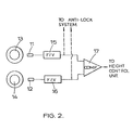
- Figure 2 is a block circuit diagram of the cornering sensor shown in Figure 1.
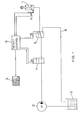
- For simplicity only a single suspension unit 1 and its associated control system is shown in Figure 1, but in a practical installation the body will be supported from each wheel of the vehicle, or at least from each wheel of one axle, by means of a similar suspension unit.
- The suspension units may be of the ram type in which each unit is effective to adjust the mounting position of the associated suspension spring within the body. Alternatively each unit may comprise an integral gas spring and damper unit, as disclosed in British Patent Specification 857 799 for example.
- A high pressure hydraulic pump 2 is arranged to draw fluid from a reservoir 3 and pump it to the suspension unit 1 through first and second solenoid-operated valves 4 and 5. Both valves are operated in response to electrical signals from an electronic height control unit 6 which receives signals from an electrical
ride height sensor 7. Thesensor 7 is associated with the suspension unit 1 in such a way that it monitors the height between the sprung and unsprung parts of the vehicle in the vicinity of the suspension unit. - The pump 2 is under the control of the control unit 6 so that the pump only operates when fluid is required by the suspension unit 1. Alternatively, the pump could be provided with means to reduce the load on the pump when fluid is not required.
- At a certain ride height, the valves 4 and 5 are in the positions shown in the drawing, that is, the second valve 5 connects the suspension unit 1 to the first valve 4, but the first valve 4 is closed. Thus, fluid is trapped in the suspension unit so that the nominal ride height of the vehicle remains constant. In order to increase the nominal ride height, the first valve 4 is moved to its alternative position so that fluid can be pumped from the reservoir 3, via valves 4 and 5, into the lower chamber of the suspension unit, thus increasing its length. When the required nominal ride height has been reached, as detected by the
sensor 7, the first valve 4 is moved back to its closed position shown. In order to reduce the nominal ride height, the second valve 5 is moved to its alternative position in which the suspension unit 1 is connected to the reservoir through a return line 8, thus enabling fluid to be dumped from the suspension unit to reduce its length. When the required height relationship has been achieved the second valve 5 is returned to its initial position. - A
cornering sensor 9 is connected to the height control unit 6 so that, whilst the vehicle is cornering, both valves 4 and 5 can be maintained in the positions shown, irrespective of any signals from theheight sensor 7, thus preventing any adjustment of ride height in response to lateral forces produced whilst cornering. The cornering sensor is described in more detail below with reference to Figure 2. - The
cornering sensor 9 comprises a pair ofwheel speed sensors wheels respective wheel voltage converter converter comparator 17 which produces an inhibit signal when one voltage differs from the other by more than a predetermined amount, indicating that the wheels are rotating at different speeds. The inhibit signal is used to inhibit the height control unit 6 as described above. (In this case the "expected difference" between the two speeds is zero.) - A single cornering sensor may be used to inhibit adjustment of all the suspension units of a vehicle. Similarly, the pump 2 and reservoir 3 will usually be shared by all the suspension units for reasons of economy.
- The outputs of the frequency/
voltage converters - The cornering sensor described above employs a fairly simple circuit, but more sophisticated circuitry may of course be used.
- In one modification, the cornering sensor includes circuitry for deriving a continuous average wheel speed difference and the system is arranged so that height adjustment is inhibited only when the instantaneous wheel speed difference departs from the average value by more than a certain amount. In this case the "expected difference" referred to above is the average wheel speed difference over a period of time. This allows automatic compensation for any inherent difference between the rotational speeds of the monitored wheels.
- The circuit may also be modified to vary the amount by which the instantaneous wheel speed difference must depart from the expected difference to preduce inhibition, in accordance with the speed of the vehicle (which may be taken from one or both speed sensors).
- Digital techniques may be used to analyse the signals produced by the two
wheel speed sensors
Claims (8)
1. A suspension system for a vehicle, comprising at least two suspension units (1) installed on opposite sides of the vehicle and adapted to maintain a suitable height relationship between the sprung and unsprung parts of the vehicle despite changes in vehicle load, and means to prevent the suspension units from being adjusted during a cornering manoeuvre, characterised by respective sensors (11, 12) for sensing the speed of rotation of each of two wheels (13, 14) on opposite sides of the vehicle, and means (17) for comparing the sensed speeds of the two wheels and producing an inhibit command when the instantaneous difference between the sensed speeds departs by more than a certain amount from an expected difference, the arrangement being such that the inhibit command inhibits adjustment of the suspension units (1).
2. A suspension system according to Claim 1, in which the speed comparison means (17) operates to produce an inhibit command in the form of an electrical inhibit signal which is used to prevent the suspension units (1) from being adjusted by inhibiting an electrical height control circuit (6).
3. A suspension system according to Claim 2, in which each suspension unit (1) is associated with respective means (7) for sensing the height between the sprung and unsprung parts of the vehicle and producing electrical height' signals which vary in accordance therewith, the height signals being fed to the height control circuit (6) which is arranged to operate respective cut-off means (4, 5) that control flow of liquid to and from each respective suspension unit (1) in response to the respective height signals in order to maintain the height relationship between the sprung and unsprung parts of the vehicle.
4. A suspension system according to Claim 3, in which the cut-off means (4,5) comprise solenoid-operated valves.
5. A suspension system according to Claim 2, 3 or 4, which includes means to produce an electrical expected difference signal corresponding to the expected difference in sensed speed between the wheels by deriving an average value for any difference between the sensed speeds, the expected difference signal being fed to the comparison means (17).
6. A suspension system according to any of Claims 2 to 5, which includes means to vary the amount by which the instantaneous speed difference must depart from the expected difference to produce the inhibit signal, in accordance with the speed of the vehicle.
7. A suspension system according to any preceding claim, in which the speed sensors (11, 12) are connected to an anti-wheel-lock braking system.
8. A suspension system according to any preceding claim, in which the wheels of which the speeds of rotation are sensed share a common axle.
Applications Claiming Priority (2)
| Application Number | Priority Date | Filing Date | Title |
|---|---|---|---|
| GB8002697 | 1980-01-26 | ||
| GB8002697 | 1980-01-26 |
Publications (2)
| Publication Number | Publication Date |
|---|---|
| EP0033204A2 true EP0033204A2 (en) | 1981-08-05 |
| EP0033204A3 EP0033204A3 (en) | 1982-03-10 |
Family
ID=10510918
Family Applications (1)
| Application Number | Title | Priority Date | Filing Date |
|---|---|---|---|
| EP81300168A Withdrawn EP0033204A3 (en) | 1980-01-26 | 1981-01-15 | Suspension systems for vehicles |
Country Status (4)
| Country | Link |
|---|---|
| US (1) | US4361346A (en) |
| EP (1) | EP0033204A3 (en) |
| JP (1) | JPS56154306A (en) |
| GB (1) | GB2068309A (en) |
Cited By (8)
| Publication number | Priority date | Publication date | Assignee | Title |
|---|---|---|---|---|
| EP0174772A2 (en) * | 1984-08-28 | 1986-03-19 | Mitsubishi Jidosha Kogyo Kabushiki Kaisha | Vehicle height control system |
| FR2590525A1 (en) * | 1985-11-22 | 1987-05-29 | Renault Vehicules Ind | Device for improving the power-transmitting adhesion of a tandem axle to a single drive bogie |
| EP0249207A2 (en) * | 1986-06-12 | 1987-12-16 | HYDAC Technology GmbH | Level-adjusting device for motor vehicles |
| EP0296756A2 (en) * | 1987-06-26 | 1988-12-28 | Ford Motor Company Limited | Vehicular controller with differential wheel speed input |
| EP0310094A2 (en) * | 1987-10-02 | 1989-04-05 | Nissan Motor Co., Ltd. | Integrated roll rigidity and differential slip control system |
| WO1989009703A1 (en) * | 1988-04-14 | 1989-10-19 | Robert Bosch Gmbh | Height regulating system for a vehicle with air suspension |
| WO1991008120A1 (en) * | 1989-11-28 | 1991-06-13 | Alfred Teves Gmbh | Combined control system for motor vehicles |
| EP0803423A2 (en) * | 1996-04-26 | 1997-10-29 | Toyota Jidosha Kabushiki Kaisha | Control system of automative vehicle |
Families Citing this family (20)
| Publication number | Priority date | Publication date | Assignee | Title |
|---|---|---|---|---|
| GB2101266B (en) * | 1981-07-09 | 1985-08-21 | Lucas Industries Ltd | Self-pumping struts for vehicle suspension systems |
| US4616163A (en) * | 1982-08-31 | 1986-10-07 | Mazda Motor Corporation | Position control system for wheeled vehicle |
| EP0115202B1 (en) * | 1982-12-27 | 1988-03-02 | Nippondenso Co., Ltd. | Shock absorber control system |
| JPS59186713A (en) * | 1983-03-18 | 1984-10-23 | Mazda Motor Corp | Suspension for automobile |
| JPS59179708U (en) * | 1983-05-20 | 1984-12-01 | 三菱自動車工業株式会社 | vehicle height control device |
| JPS6069711U (en) * | 1983-10-20 | 1985-05-17 | トキコ株式会社 | Damping force adjustable hydraulic shock absorber |
| JPS60113710A (en) * | 1983-11-24 | 1985-06-20 | Mazda Motor Corp | Cornering sensor for car |
| NL8402348A (en) * | 1983-12-22 | 1985-07-16 | Multinorm Bv | VEHICLE, IN PARTICULAR AGRICULTURAL MACHINE, WITH AT LEAST TWO SPRING WHEELS HANGED FROM THE FRAME. |
| US4568096A (en) * | 1984-04-19 | 1986-02-04 | General Motors Corporation | Automatic vehicle level control |
| US4540188A (en) * | 1984-04-19 | 1985-09-10 | General Motors Corporation | Automatic vehicle level control |
| IT1179048B (en) * | 1984-08-14 | 1987-09-16 | Marelli Autronica | LINEAR MOVEMENT TRANSDUCER IN ELECTRIC SIGNALS PARTICULARLY FOR AUTOMATIC LEVELING DEVICES FOR SUSPENSIONS OF A VEHICLE |
| US4641856A (en) * | 1985-07-24 | 1987-02-10 | Ford Motor Company | Motor vehicle anti-roll stabilizer system |
| US4621833A (en) * | 1985-12-16 | 1986-11-11 | Ford Motor Company | Control system for multistable suspension unit |
| US4905783A (en) * | 1987-06-26 | 1990-03-06 | Ford Motor Company | Vehicular controller with differential wheel speed input |
| JPH02182521A (en) * | 1989-01-10 | 1990-07-17 | Nissan Motor Co Ltd | Suspension control device |
| JPH0794202B2 (en) * | 1989-02-28 | 1995-10-11 | トヨタ自動車株式会社 | Fluid pressure active suspension |
| US6189897B1 (en) * | 1999-09-07 | 2001-02-20 | Cathy D. Santa Cruz | Steering actuated shock system for vehicles |
| US7641181B2 (en) * | 2003-01-24 | 2010-01-05 | Liquid Spring Technologies, Inc. | Distributed power suspension system |
| US8191904B2 (en) * | 2009-10-02 | 2012-06-05 | Barksdale, Inc. | Hybrid leveling system |
| US10479159B2 (en) | 2016-04-04 | 2019-11-19 | Barksdale, Inc. | Ride height leveling with selectable configurations: system and method |
Citations (2)
| Publication number | Priority date | Publication date | Assignee | Title |
|---|---|---|---|---|
| US2844384A (en) * | 1956-06-18 | 1958-07-22 | Gen Motors Corp | Control apparatus for fluid suspension system |
| FR2052146A5 (en) * | 1969-07-22 | 1971-04-09 | Messier Fa |
Family Cites Families (5)
| Publication number | Priority date | Publication date | Assignee | Title |
|---|---|---|---|---|
| US3910594A (en) * | 1971-05-18 | 1975-10-07 | Hoesch Ag | Control arrangement for a suspension system using a pressure medium |
| JPS5210571B2 (en) * | 1973-03-12 | 1977-03-25 | ||
| JPS506017A (en) * | 1973-05-21 | 1975-01-22 | ||
| JPS5143521A (en) * | 1974-10-14 | 1976-04-14 | Nissan Motor | Jidoshano kagensokujishataishiseiseigyosochi |
| DE2716476C2 (en) * | 1977-04-14 | 1985-07-11 | Robert Bosch Gmbh, 7000 Stuttgart | Level control device for motor vehicles |
-
1981
- 1981-01-15 EP EP81300168A patent/EP0033204A3/en not_active Withdrawn
- 1981-01-16 GB GB8101418A patent/GB2068309A/en not_active Withdrawn
- 1981-01-26 JP JP1009381A patent/JPS56154306A/en active Pending
- 1981-01-26 US US06/228,586 patent/US4361346A/en not_active Expired - Fee Related
Patent Citations (2)
| Publication number | Priority date | Publication date | Assignee | Title |
|---|---|---|---|---|
| US2844384A (en) * | 1956-06-18 | 1958-07-22 | Gen Motors Corp | Control apparatus for fluid suspension system |
| FR2052146A5 (en) * | 1969-07-22 | 1971-04-09 | Messier Fa |
Non-Patent Citations (2)
| Title |
|---|
| ATZ (AUTOMOBILTECHNISCHE ZEITSCHRIFT) Vol. 81, No. 11, November 1979 Stuttgart G. HEYER "Zum Entwicklunggsstand hydropneumatischer Niveauregelanlagen im Personenenwagen" page 559 to 566 * page 565, paragraph 5.2. * * |
| DESIGN ENGINEERING, Vol. 44, No. 5, May 1979, London "FLUID POWER: its place in car design" pages 59 to 65 * page 63, left-hand column, last paragraph to page 65, left-hand column, first paragraph * * |
Cited By (15)
| Publication number | Priority date | Publication date | Assignee | Title |
|---|---|---|---|---|
| US4803630A (en) * | 1984-08-28 | 1989-02-07 | Mitsubishi Denki Kabushiki Kaisha | Vehicle height control system |
| EP0174772A3 (en) * | 1984-08-28 | 1986-06-04 | Mitsubishi Jidosha Kogyo Kabushiki Kaisha | Vehicle height control system |
| EP0174772A2 (en) * | 1984-08-28 | 1986-03-19 | Mitsubishi Jidosha Kogyo Kabushiki Kaisha | Vehicle height control system |
| FR2590525A1 (en) * | 1985-11-22 | 1987-05-29 | Renault Vehicules Ind | Device for improving the power-transmitting adhesion of a tandem axle to a single drive bogie |
| EP0249207A2 (en) * | 1986-06-12 | 1987-12-16 | HYDAC Technology GmbH | Level-adjusting device for motor vehicles |
| EP0249207A3 (en) * | 1986-06-12 | 1988-11-02 | Gesellschaft Fur Hydraulik-Zubehor Mbh | Level-adjusting device for motor vehicles |
| EP0296756A2 (en) * | 1987-06-26 | 1988-12-28 | Ford Motor Company Limited | Vehicular controller with differential wheel speed input |
| EP0296756A3 (en) * | 1987-06-26 | 1990-05-16 | Ford Motor Company Limited | Vehicular controller with differential wheel speed input |
| EP0310094A2 (en) * | 1987-10-02 | 1989-04-05 | Nissan Motor Co., Ltd. | Integrated roll rigidity and differential slip control system |
| EP0310094A3 (en) * | 1987-10-02 | 1989-12-27 | Nissan Motor Co., Ltd. | Integrated roll rigidity and differential slip control system |
| US4921060A (en) * | 1987-10-02 | 1990-05-01 | Nissan Motor Co., Ltd. | Integrated roll rigidity and differential slip control system |
| WO1989009703A1 (en) * | 1988-04-14 | 1989-10-19 | Robert Bosch Gmbh | Height regulating system for a vehicle with air suspension |
| WO1991008120A1 (en) * | 1989-11-28 | 1991-06-13 | Alfred Teves Gmbh | Combined control system for motor vehicles |
| EP0803423A2 (en) * | 1996-04-26 | 1997-10-29 | Toyota Jidosha Kabushiki Kaisha | Control system of automative vehicle |
| EP0803423A3 (en) * | 1996-04-26 | 1998-12-23 | Toyota Jidosha Kabushiki Kaisha | Control system of automative vehicle |
Also Published As
| Publication number | Publication date |
|---|---|
| EP0033204A3 (en) | 1982-03-10 |
| US4361346A (en) | 1982-11-30 |
| GB2068309A (en) | 1981-08-12 |
| JPS56154306A (en) | 1981-11-28 |
Similar Documents
| Publication | Publication Date | Title |
|---|---|---|
| US4361346A (en) | Suspension systems for vehicles | |
| EP0492782B1 (en) | Automotive apparatus and method for dynamically determining the centripetal force of a vehicle | |
| US7063334B2 (en) | Vehicle stability system using active tilting mechanism | |
| EP0285153B1 (en) | Actively controlled automotive suspension system with acceleration and angular velocity dependent anti-pitching and/or anti-rolling feature | |
| EP0193744B1 (en) | Vehicle active suspension system incorporating acceleration detecting means | |
| EP0249246B1 (en) | Actively controlled automotive suspension system with adjustable rolling stability | |
| KR920004520B1 (en) | System for control of vehicle suspension | |
| US5430647A (en) | Method and apparatus for maintaining vehicular ride height | |
| US4903983A (en) | Actively controlled automotive suspension system with improved cornering characteristics | |
| US6384719B1 (en) | Process to prevent the overturning of a vehicle | |
| CA1308462C (en) | Automotive system for dynamically determining road adhesion | |
| US20060076741A1 (en) | Vehicle stability system: using active tilting mechanism as a counter measure to natural tilt | |
| EP0306004B1 (en) | Electronic controlled fluid suspension system | |
| EP0345817B1 (en) | Anti-rolling controlling system for automotive active suspension system with road friction dependent variable control characteristics | |
| EP0249209A2 (en) | Actively controlled automotive suspension system with improved damping characteristics | |
| US20060267296A1 (en) | Electronic control of vehicle air suspension | |
| US6688612B1 (en) | Vehicle suspensions | |
| US5342079A (en) | Control apparatus for vehicle suspension mechanism | |
| US5013067A (en) | Method and apparatus for controlling vehicle height | |
| EP0364965A2 (en) | Active suspension system for an automotive vehicle with slip angle dependent control for enhanced steering characteristics | |
| EP1104357B1 (en) | Vehicle suspensions | |
| EP1219475A1 (en) | Apparatus for controlling semi-active suspension system | |
| GB2106053A (en) | Vehicle suspension system | |
| GB2106054A (en) | Vehicle suspension system | |
| Sommer | Electronic air suspension with continuous damping control |
Legal Events
| Date | Code | Title | Description |
|---|---|---|---|
| PUAI | Public reference made under article 153(3) epc to a published international application that has entered the european phase |
Free format text: ORIGINAL CODE: 0009012 |
|
| AK | Designated contracting states |
Designated state(s): DE FR IT NL |
|
| 17P | Request for examination filed |
Effective date: 19811019 |
|
| PUAL | Search report despatched |
Free format text: ORIGINAL CODE: 0009013 |
|
| AK | Designated contracting states |
Designated state(s): DE FR IT NL |
|
| RAP1 | Party data changed (applicant data changed or rights of an application transferred) |
Owner name: LUCAS INDUSTRIES PLC |
|
| STAA | Information on the status of an ep patent application or granted ep patent |
Free format text: STATUS: THE APPLICATION IS DEEMED TO BE WITHDRAWN |
|
| 18D | Application deemed to be withdrawn |
Effective date: 19831206 |
|
| RIN1 | Information on inventor provided before grant (corrected) |
Inventor name: HARRIS, ALAN LESLIE |