EP0034516A1 - Hyperthermal treating device with an electrical field at a radio frequency - Google Patents
Hyperthermal treating device with an electrical field at a radio frequency Download PDFInfo
- Publication number
- EP0034516A1 EP0034516A1 EP81400138A EP81400138A EP0034516A1 EP 0034516 A1 EP0034516 A1 EP 0034516A1 EP 81400138 A EP81400138 A EP 81400138A EP 81400138 A EP81400138 A EP 81400138A EP 0034516 A1 EP0034516 A1 EP 0034516A1
- Authority
- EP
- European Patent Office
- Prior art keywords
- applicators
- flexible
- power
- patient
- conductive
- Prior art date
- Legal status (The legal status is an assumption and is not a legal conclusion. Google has not performed a legal analysis and makes no representation as to the accuracy of the status listed.)
- Ceased
Links
Images

Classifications
-
- A—HUMAN NECESSITIES
- A61—MEDICAL OR VETERINARY SCIENCE; HYGIENE
- A61N—ELECTROTHERAPY; MAGNETOTHERAPY; RADIATION THERAPY; ULTRASOUND THERAPY
- A61N1/00—Electrotherapy; Circuits therefor
- A61N1/02—Details
- A61N1/04—Electrodes
- A61N1/06—Electrodes for high-frequency therapy
-
- A—HUMAN NECESSITIES
- A61—MEDICAL OR VETERINARY SCIENCE; HYGIENE
- A61N—ELECTROTHERAPY; MAGNETOTHERAPY; RADIATION THERAPY; ULTRASOUND THERAPY
- A61N1/00—Electrotherapy; Circuits therefor
- A61N1/40—Applying electric fields by inductive or capacitive coupling ; Applying radio-frequency signals
- A61N1/403—Applying electric fields by inductive or capacitive coupling ; Applying radio-frequency signals for thermotherapy, e.g. hyperthermia
Abstract
L'invention a pour objet un dispositif de traitement thérapeutique par hyperthermie comprenant und générateur de puissance (2) à fréquence radio, au moins deux applicateurs (7, 8) de cette puissance au corps du patient et un ensemble de mesures des températures en plusieurs points de la zone traitée. Dans le dispositif de l'invention, les applicateurs (7,8) sont réalisés dans des matériaux souples et déformables absorbant l'humidité et la face desdits applicateurs en contact avec la peau du patient est conductrice de l'électricité, reliée électriquement aux sorties de puissance (4) dudit générateur (2) et en bon contact électrique avec la peau du patient.The subject of the invention is a device for therapeutic treatment by hyperthermia comprising a power generator (2) at radio frequency, at least two applicators (7, 8) of this power to the patient's body and a set of temperature measurements in several points of the treated area. In the device of the invention, the applicators (7,8) are made of flexible and deformable materials absorbing moisture and the face of said applicators in contact with the patient's skin is electrically conductive, electrically connected to the outlets power (4) of said generator (2) and in good electrical contact with the patient's skin.
Description
Le dispositif objet de la présente invention fait partie du matériel à utilisation thérapeutique.The device which is the subject of the present invention is part of the material for therapeutic use.
La présente invention a pour objet un dispositif de traitement médical de certaines maladies humaines, tel que les cancers.The present invention relates to a device for medical treatment of certain human diseases, such as cancers.
Plus particulièrement, il s'agit d'un dispositif de traitement local ou loco-régional des cancers, en particulier des cancers profonds localisés, traitement réalisé par une surchauffe de la masse tumorale, obtenue sans affecter les tissus sains environnants.More particularly, it is a device for local or loco-regional treatment of cancers, in particular localized deep cancers, treatment carried out by overheating of the tumor mass, obtained without affecting the surrounding healthy tissue.
Ce traitement hyperthermique est obtenu, de façon connue, par l'action d'un générateur de puissance à fréquence radio, par exemple à 13,56 MHz, laquelle puissance est appliquée au moyen d'applicateurs ou électrodes à la zone à traiter du corps du patient, tandis que la température de ladite zone est contrôlée. Cette zone comprend la masse tumorale dont on cherche à élever la température au maximum, pour obtenir la nécrose de ladite masse, et les tissus sains environnants dont la température ne doit pas dépasser 43°C.This hyperthermic treatment is obtained, in a known manner, by the action of a power generator at radio frequency, for example at 13.56 MHz, which power is applied by means of applicators or electrodes to the area to be treated of the body. of the patient, while the temperature of said area is controlled. This zone includes the tumor mass, the temperature of which is sought to be raised as much as possible, in order to obtain the necrosis of said mass, and the surrounding healthy tissue, the temperature of which must not exceed 43 ° C.
Les différentes températures obtenues en différents points de la zone traitées sont le résultat de trois paramètres ; la puissance électrique appliquée, la nature des tissus et l'irrigation sanguine desdits tissus. L'action de ces trois paramètres permet d'atteindre un équilibre dynamique régi par des lois simples :
- - les points les plus chauffés sont aussi les plus refroidis si l'irrigation par le sang est suffisante,
- - les tissus sains sont bien chauffés et leur température est régulée, au-dessous de la température létale, par le débit sanguin,
- - les os, et les tissus adipeux reçoivent peu de puissance, mais cependant ils risquent d'Être surchauffés car ils sont mal irrigués dans leur masse,
- - les tumeurs cancéreuses reçoivent beaucoup de puissance car elles sont bien hydratées, et, étant mal irriguées elles sont rapidement surchauffées, les points les plus chauds étant situés au centre des tumeurs.
- - the most heated points are also the most cooled if the blood supply is sufficient,
- - healthy tissues are well heated and their temperature is regulated, below the lethal temperature, by blood flow,
- - the bones, and the adipose tissues receive little power, but nevertheless they are likely to be overheated because they are poorly irrigated in their mass,
- - cancerous tumors receive a lot of power because they are well hydrated, and, being poorly irrigated they are quickly overheated, the hottest points being located in the center of the tumors.
Des dispositifs pour la mise en oeuvre d'un tel traitement par hyperthermie sont déjà connus, en particulier, par l'article "Tumor Eradication in the Rabbit by Radiofrequen- cy Heating" publie par J.A. Dickson S.A. Shab, D. Waggott and W.B. Whalley dans la revue Cancer Reeearch vol. 37 july 1977 p..2162-2169. Toutefois le dispositif décrit dans cet article n'est pas adapté pour les traitements humains, en particulier parce qu'il utilise pour appliquer la tension électrique de traitement au coprs du patient des applicateurs rigides qui risquent de meurtrir le patient, s'ils sont appliqués avec une forte pression, ou de provoquer des brûlures, s'ils ne sont pas parfaitement appliqués sur la peau du patient.Devices for the implementation of such a hyperthermia treatment are already known, in particular, by the article "Tumor Eradication in the Rabbit by Radiofrequence cy Heating" published by JA Dickson SA Shab, D. Waggott and WB Whalley in the journal Cancer Reeearch vol. 37 July 1977 p..2162-2169. However, the device described in this article is not suitable for human treatments, in particular because it uses to apply the electrical treatment voltage to the patient's body, rigid applicators which risk bruising the patient, if they are applied. with strong pressure, or cause burns, if they are not perfectly applied to the patient's skin.
Fait également partie de l'art antérieur, un dispositif de traitement hyperthermique connu sous la marque déposée "Magnétrode". Ce dispositif fabriqué et distribué par HYPERTHERMIA Division of Henry Electronics, Inc utilise de préférence le champ magnétique créé par un solénoïde ou un tore entourant la zone à traiter ou placé au voisinage de la surface à traiter.Also part of the prior art, a hyperthermic treatment device known under the trademark "Magnetrode". This device manufactured and distributed by HYPERTHERMIA Division of Henry Electronics, Inc. preferably uses the magnetic field created by a solenoid or a torus surrounding the area to be treated or placed in the vicinity of the surface to be treated.
Tous ces dispositifs connus, de même que le dispositif selon l'invention, utilisent un générateur de radiofréquences à 13,56 MHz, toutefois le dispositif selon l'invention se distingue des dispositifs connus essentiellement par la nature de ses applicateurs, par le système particulier de mesure des températures dans la zone soumise au traitement et par la façon particulière dont est réalisé l'accord du générateur de puissance en fonction de l'impédance de charge effectivement mise en oeuvre.All these known devices, as well as the device according to the invention, use a 13.56 MHz radio frequency generator, however the device according to the invention differs from the devices known essentially by the nature of its applicators, by the particular system. for measuring temperatures in the area subjected to treatment and by the particular way in which the tuning of the power generator is carried out of the load impedance actually implemented.
Pour cela, le dispositif selon l'invention, qui se compose d'un générateur de puissance à fréquence radio, d'au moins deux applicateurs de cette puissance au corps du patient, d'un ensemble de mesures de températures en plusieurs points de la zone traitée, est caractérisé en ce que les applicateurs sont réalisés avec des matériaux souples et déformables, qu'ils absorbent l'humidité, qu'ils sont conducteurs électriques, reliés électriquement aux sorties de puissance dudit générateur et en bon contact électrique avec la peau du patient.For this, the device according to the invention, which consists of a radio frequency power generator, at least two applicators of this power to the patient's body, a set of temperature measurements at several points of the treated area, is characterized in that the applicators are made with flexible and deformable materials, that they absorb moisture, that they are electrical conductors, electrically connected to the power outputs of said generator and in good electrical contact with the skin of the patient.
A titre d'exemple non limitatif, lesdits applicateurs se composent Essentiellement d'un tissu conducteur électrique souple dont l'une des faces, ou surface efficace, imprégnée d'un gel conducteur électrique, est en contact direct avec la peau du patient dont l'autre face est en contact avec la première face d'un tricot métallique conducteur sur l'autre face duquel, d'une part sont soudés individuellement, et selon une répartition a peu près uniforme, chaque brin d'un conducteur multibrins souple gainé d'un plastique isolant dans sa partie non en contact avec ledit tricot, et , d'autre part, est appliquée une plaque de mousse élastique de densité moyenne recouverte elle-même d'une couche protectrice souple sur laquelle sont appliquées, en partie, une ou plusieurs bandes élastiques adhésives dont les autres parties adhèrent à la peau du patient.By way of nonlimiting example, said applicators essentially consist of a flexible electrically conductive fabric of which one of the faces, or effective surface, impregnated with an electrically conductive gel, is in direct contact with the skin of the patient whose the other face is in contact with the first face of a metallic conductive knit on the other face of which, on the one hand are individually welded, and in an approximately uniform distribution, each strand of a flexible multi-strand conductor sheathed 'an insulating plastic in its part not in contact with said knitted fabric, and, on the other hand, is applied a plate of elastic foam of medium density covered itself with a flexible protective layer on which are applied, in part, a or several elastic adhesive bands, the other parts of which adhere to the patient's skin.
Selon une variante de réalisation de la présente invention, ladite plaque de mousse élastique peut Être remplacée par un ballonnet gonflable. Dans ce cas ledit ballonnet gon- flable qui assure la pression nécessaire à l'application du tissu conducteur souple sur la peau du patient, est lui-même entouré de compresses absorbantes destinées à absorber l'humidité.According to an alternative embodiment of the present invention, said elastic foam plate can be replaced by an inflatable balloon. In this case said inflatable balloon which provides the pressure necessary for the application of the flexible conductive tissue on the patient's skin, is itself surrounded by absorbent pads intended to absorb moisture.
Toujours selon la présente invention lesdits applicateurs ont une surface efficace, qui est celle du tissu conducteur souple, adaptée à la zone à traiter, le tricot métallique conducteur souple de surface plus réduite est centré sur ledit tissu conducteur souple et la plaque de mousse, de surface au moins identique au tissu conducteur souple, recouvre l'ensemble du tissu conducteur et du tricot métallique conducteur.Still according to the present invention, said applicators have an effective surface, which is that of the flexible conductive fabric, adapted to the area to be treated, the flexible metallic conductive knit with a smaller surface area is centered on said flexible conductive fabric and the foam plate, surface at least identical to the flexible conductive fabric, covers all of the conductive fabric and the conductive metallic knit.
Le dispositif de traitement thérapeutique par hyperthermie selon l'invention qui comporte, entre autres choses, un ensemble de mesures de températures en plusieurs points de la zone traitée comprenant essentiellement n thermocouples placés chacun à l'intérieur d'une aiguille hypodermique est également caractérisé en ce que sur chacun des deux fils de chaque thermocouple est inséré un filtre passe-bas ou coupe bande le plus près possible de la sortie dudit thermocouple du corps du patient, que la sortie de chacun de ces filtres est reliée à l'entrée d'un dispositif de commutation et de comparaison des températures et en ce la sortie de ce dispositif de comparaison et de commutation est reliée à travers un filtre passe-bas à l'entrée d'un enregistreur essentiellement à vibreur et amplificateur alternatif.The device for therapeutic treatment by hyperthermia according to the invention which comprises, among other things, a set of temperature measurements at several points of the treated area essentially comprising n thermocouples each placed inside a hypodermic needle is also characterized in that on each of the two wires of each thermocouple is inserted a low-pass filter or band cutter as close as possible to the outlet of said thermocouple from the patient's body, that the outlet of each of these filters is connected to the inlet of a device for switching and comparing temperatures and in this the output of this device for comparing and switching is connected through a low-pass filter to the input of a recorder essentially with vibrator and alternating amplifier.
Toujours selon la présente invention, le dispositif de commutation et de comparaison des températures comprend essentiellement un commutateur et une plaquette de 2 (n+1) points de raccordements isothermes, chaque point de raccordement étant relié, d'une part, respectivement à l'un des 2 fils des n thermocouples ou à l'un des 2 fils d'un thermocouple de référence et, d'autre part, pour,les 2;n + 1 premiers points de raccordement aux bornes d'entrée du commutateur rotatif et pour le point de raccordement 2 n + 2 directement à la deuxième borne de sortie du dispositif de commutation et de comparaison dont la première borne de sortie est reliée à la borne de sortie du commutateur.Still according to the present invention, the device for switching and comparing temperatures essentially comprises a switch and a plate of 2 (n + 1) isothermal connection points, each connection point being connected, on the one hand, respectively to the one of the 2 wires of the n thermocouples or one of the 2 wires of a reference thermocouple and, on the other hand, for the 2; n + 1 first connection points at the input terminals of the rotary switch and for the connection point 2 n + 2 directly to the second output terminal of the switching and comparison device, the first output terminal of which is connected to the switch output terminal.
Toujours selon l'invention, ledit thermocouple de réfé- rende est un thermocouple de même nature que les thermocouples de mesure et il est placé en permanence dans un bain thermostatique composé d'un mélange d'eau distillée et de glace pure pilée dont la température est contrôlée par un ou plusieurs thermomètres de précision.Still according to the invention, said reference thermocouple is a thermocouple of the same nature as the measurement thermocouples and it is permanently placed in a thermostatic bath composed of a mixture of distilled water and pure crushed ice whose temperature is controlled by one or more precision thermometers.
Le dispositif selon l'invention peut être encore caractérisé en ce qu'il comporte à proximité immédiate des applicateurs, un circuit d'accord permettant d'adapter la puissance directe émise par ledit générateur en fonction de la disposition des applicateurs de puissance de façon à obtenir une puissance réfléchie pratiquement nulle.The device according to the invention can be further characterized in that it includes, in the immediate vicinity of the applicators, a tuning circuit making it possible to adapt the direct power emitted by said generator according to the arrangement of the power applicators so as to obtain practically zero reflected power.
Toujours selon l'invention, ledit dispositif comporte au moins deux applicateurs dont l'un est relié à un potentiel alternatif et l'autre à un potentiel nul, ou les deux à un potentiel alternatif.Still according to the invention, said device comprises at least two applicators, one of which is connected to an alternating potential and the other to a zero potential, or both to an alternating potential.
Dans une variante du dispositif selon l'invention comportant trois applicateurs, l'un est relié à un potentiel alternatif et les deux autres à un potentiel nul, ou vice-versa.In a variant of the device according to the invention comprising three applicators, one is connected to an alternating potential and the other two to a zero potential, or vice versa.
Dans une autre variante du dispositif selon l'invention, les applicateurs reliés à un potentiel alternatif comporteront avantageusement une zone centrale conductrice reliée audit potentiel alternatif, une zone isolante entourant ladite zone centrale et une zone externe conductrice reliée ou non à un potentiel et entourant ladite zone isolante.In another variant of the device according to the invention, the applicators connected to an alternating potential will advantageously include a central conductive zone connected to said alternating potential, an insulating zone surrounding said central zone and an external conductive zone connected or not to a potential and surrounding said insulating zone.
Selon une autre variante de la présente invention le générateur de puissance comporte p tubes de puissance alimentant p sorties déphasées de 2 π reliées à, au moins, 2 p applicateurs de puissance. p Selon cette dernière variante, lesdits 2 p applicateurs seront avantageusement placés sur le corps du patient de telle sorte que les p champs électriques ainsi créés contiennent tous la zone à traiter.According to another variant of the present invention, the power generator comprises p power tubes supplying p phase-shifted outputs of 2 π connected to, at least, 2 p power applicators. p According to this last variant, said 2 p applicators will advantageously be placed on the patient's body so that the p electric fields thus created all contain the area to be treated.
Dans tous les cas de réalisation de la présente invention il est prévu que la tension distribuée sur les applicateurs ne comporte pas de composante continue et ce, grâce à une double sécurité. A titre d'exemple, deux condensateurs l'un de 100 pF et l'autre de 220 pF sont mis en série sur le circuit de sortie du générateur de puissance.In all the embodiments of the present invention, it is provided that the voltage distributed over the applicators does not include a continuous component, and this, thanks to double security. For example, two capacitors, one of 100 pF and the other of 220 pF, are connected in series on the output circuit of the power generator.
Le principal avantage du dispositif thérapeutique selon l'invention réside dans la nature souple de ses applicateurs par ailleurs parfaitement conducteurs électriques ce qui permet un contact électrique direct avec la peau du patient et évite ainsi tout risque de brûlure dudit patient.The main advantage of the therapeutic device according to the invention lies in the flexible nature of its applicators, which are also perfectly electrically conductive, which allows direct electrical contact with the patient's skin and thus avoids any risk of burns to said patient.
Un autre avantage du dispositif thérapeutique selon l'invention réside dans la possibilité de choisir le nombre, la forme et les dimensions des applicateurs en fonction de chaque cas à traiter.Another advantage of the therapeutic device according to the invention lies in the possibility of choosing the number, the shape and the dimensions of the applicators as a function of each case to be treated.
Un autre avantage du dispositif thérapeutique selon l'invention réside dans la grande précision du dispositif de mesure des températures en différents points de la zone traitée et ceci en cours de traitement, le dit dispositif de mesure des températures étant rendu selon l'invention insensible au champ des ondes radiofréquences émises par le générateur de puissance et par tout le circuit électrique qui lui est connecté.Another advantage of the therapeutic device according to the invention lies in the high precision of the device for measuring temperatures at different points in the treated area and this during treatment, said device for measuring temperatures being made according to the invention insensitive to field of radiofrequency waves emitted by the power generator and by the entire electrical circuit connected to it.
Un autre avantage du dispositif thérapeutique selon l'invention réside dans la possibilité d'accord réglable de l'impédance de charge du générateur de puissance ; de cet accord réglable résulte une meilleure utilisation de la puissance émise et une réduction du champ parasite créé. D'autres caractéristiques et d'autres avantages du dispositif thérapeutique selon l'invention apparaitront au cours de la description qui suit pour la compréhension de laquelle on se reportera aux figures données en annexe.
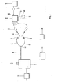
- - La figure 1 est une vue d'ensemble schématisée du dispositif thérapeutique selon l'invention.
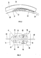
- - La figure 2 représente la vue en coupe d'un des applicateurs selon l'invention.
- - La figure 3 représente un exemple de réalisation du filtre placé sur chaque fil de thermocouple près du corps du patient.
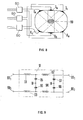
- - La figure 4 représente schématiquement le dispositif de commutation et de comparaison des températures.
- - La figure 5 représente le schéma électrique du dispositif d'accord.
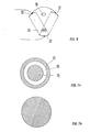
- - La figure 6 représente un exemple de positionnement de trois applicateurs.
- - La figure 7-a et la figure 7-b représentent un exemple de forme de deux applicateurs.
- - La figure 8 représente un exemple d'utilisation d'un dispositif selon l'invention utilisant un générateur à trois sorties déphasées.
- - La figure 9 représente le schéma électrique du filtre utilisé à l'entrée de l'enregistreur de température.
- - Figure 1 is a schematic overview of the therapeutic device according to the invention.
- - Figure 2 shows the sectional view of one of the applicators according to the invention.
- - Figure 3 shows an embodiment of the filter placed on each thermocouple wire near the patient's body.
- - Figure 4 shows schematically the switching device and temperature comparison.
- - Figure 5 shows the electrical diagram of the tuning device.
- - Figure 6 shows an example of positioning three applicators.
- - The figure 7-a and the figure 7-b represent an example of form of two applicators.
- - Figure 8 shows an example of the use of a device according to the invention using a generator with three phase-shifted outputs.
- - Figure 9 shows the electrical diagram of the filter used at the input of the temperature recorder.
L'ensemble du dispositif selon l'invention représenté sur la figure 1 comporte esssentiellement un régulateur de tension 1, un générateur de puissance 2 et son tableau de commande 3, une ligne de sortie de puissance 4 qui se termine en 5 et 6 par les deux fils d'alimentation des applicateurs souples 7 et 8.The entire device according to the invention shown in FIG. 1 essentially comprises a
Fait également partie du dispositif selon l'invention la chaîne de mesure des températures qui se compose essentiellement de n thermocouples, tel que 10, et de n filtres passe-bas ou coupe-bande tel que 11, tous reliés à un commutateur de thermocouples 12 comportant n + 1 paires de bornes d'entrée dont la (n + 1)ième paire est reliée à un thermocouple 14 dit de référence plongé dans un bain de référence 15. La paire de borne de sortie 16 dudit commutateur de thermocouple 12 est reliée à l'entrée d'un filtre passe-bas 17 dont la sortie est reliée à l'entrée d'un dispositif enregistreur 18.Also part of the device according to the invention is the temperature measurement chain which essentially consists of n thermocouples, such as 10, and n low-pass or notch filters such as 11, all connected to a
Ne font pas réellement partie du dispositif selon l'invention, mais sont nécessaires à sa bonne mise en oeuvre un bain thermostatique 20 et une charge étalon 21, par exemple de 50 Ω. Avant la mise en oeuvre du dispositif thérapeutique selon l'invention, le bain thermostatique 20 sert à étalonner les thermocouples tels que 10, et la charge étalon 21 sert à prérégler le générateur de puissance 2 et à vérifier son bon fonctionnement.Do not really form part of the device according to the invention, but are necessary for its proper implementation a
La figure 2 représente une vue en coupe transversale des applicateurs selon l'invention. Sur cette figure sont représentés, en 30, un tissu souple conducteur, de fils textiles absorbants et de fils métalliques très bons conducteurs, en 31, un tricot métallique conducteur sur lequel sont soudés individuellement, tel qu'en 32, les différents brins d'un conducteur souple 33 isolé, dans sa partie extérieure à l'applicateur proprement dit, par un revêtement plastique 34.Figure 2 shows a cross-sectional view of the applicators according to the invention. In this figure are shown, at 30, a flexible conductive fabric, absorbent textile yarns and very good conductive metallic threads, at 31, a conductive metallic knitted fabric on which are individually welded, such as at 32, the different strands of a
L'ensemble ainsi formé est recouvert par une plaque de mousse élastique moyenne densité 35, elle-même recouverte d'un revêtement souple 36, posé sur la face supérieure de ladite plaque 35.The assembly thus formed is covered by a plate of elastic
Ce revêtement 36 lisse à sa partie supérieure permet la fixation aisée dudit applicateur sur le corps du patient au moyen de bandes élastiques adhésives médicales du type "Albuplast", adhérant par ailleurs à la peau du patient.This
A titre d'exemple non limitatif, le tissu conducteur souple est un tissu utilisé habituellement pour la confection des vêtements des escrimeurs de compétition. Ce tissu est alors découpé à la forme exacte que l'on désire pour l'applicateur. Sa surface efficace est ensuite enduite d'un gel conducteur du type de celui utilisé lors de l'établissement d'électrocardiogrammes et appliqué fermement à l'endroit prévu. Ensuite est posé sur ce tissu conducteur souple, une, deux ou trois épaisseurs de tricot métallique sur les mailles duquel sont soudés individuellement et selon une répartition à peu près uniforme les brins du fil d'alimentation. Toujours à titre d'exemple, ledit fil est du câble THT 15 KV du type câble non antiparasité utilisé autrefois pour l'alimentation des bougies des automobiles.By way of nonlimiting example, the flexible conductive fabric is a fabric usually used for the clothing of competitive fencers. This fabric is then cut to the exact shape that is desired for the applicator. Its effective surface is then coated with a conductive gel of the type used in the establishment of EKGs and applied firmly to the intended location. Then is placed on this flexible conductive fabric, one, two or three layers of metallic knitted fabric on the meshes of which are individually welded and in a roughly uniform distribution the strands of the supply wire. Still by way of example, said wire is
En se reportant à la figure 1, les thermocouples, tel que 10, sont du type chromel - alumel. On trouve dans le commerce des fils très fins chromel - alumel qui sont déjà placés dans une gaine en acier inoxydable remplie avec de la poudre de magnésie ; il suffit alors de faire avec soin la soudure dudit thermocouple et de glisser celui-ci dans un cathéter ou aiguille hypodermique dont le diamètre extérieur est de l'ordre de 0,6 à 1 mm, de telle sorte que ladite soudure de thermocouple soit légèrement sortie dudit cathéter. Une radiographie des thermocouples permet de contrôler le bon positionnement de l'ensemble de façon à Être sùr que le thermocouple mesure la température à l'extrémité de la sonde et non la température à l'intérieur de l'aiguille hypodermique.Referring to Figure 1, thermocouples, such as 10, are of the chromel - alumel type. There are commercially available very fine chromel - alumel wires which are already placed in a stainless steel sheath filled with magnesia powder; it is then sufficient to carefully solder said thermocouple and to slide it into a hypodermic catheter or needle whose outside diameter is of the order of 0.6 to 1 mm, so that said thermocouple weld is slightly exit from said catheter. An X-ray of the thermocouples makes it possible to check the correct positioning of the assembly so as to be sure that the thermocouple measures the temperature at the end of the probe and not the temperature inside the hypodermic needle.
Immédiatement à la sortie de l'aiguille hypodermique les fils chromel - alumel sont interrompus par un filtre, tel que 11, dont un exemple de réalisation détaillée est représenté par la figure 3.Immediately at the outlet of the hypodermic needle, the chromel - alumel wires are interrupted by a filter, such as 11, a detailed embodiment of which is shown in FIG. 3.
On voit sur cette figure 3 que les deux fils du thermocouple 40 arrivent respectivement sur les plots 41 et 42. Chacun de ces plots comporte un connecteur d'arrivée 43 et un connecteur de départ 44 qui sont isothermes : pour cela ils sont montés sur une plaquette d'oxyde de béryllium qui est un bon conducteur thermique tout en étant un isolant électrique. Entre ces deux connecteurs est inséré le filtre proprement dit qui est ici, à titre d'exemple, un circuit bouchon composé d'uneself 45, d'un condensateur fixe 46 et d'un condensateur variable 47, mis en parallèle. A titre d'exemple, la self 45 est une self bobinée en argent d'une valeur de 2 µH, le condensateur 46 est un condensateur céramique de 68 pF et le condensateur 47 est un condensateur ajustable de 1 à 30 pF ; toutes les connections entre les connecteurs d'arrivée 43 et les connecteurs de départ 44 sont en fils d'argent et à la sortie du connecteur de départ 44 on utilise de nouveau des fils chromel - alumel 48.It can be seen in this FIG. 3 that the two wires of the thermocouple 40 arrive respectively on the
La figure 4 représente le commutateur 12 permettant, d'une part, de sélectionner le thermocouple 10 dont l'on désire enregistrer les variations de température et, d'autre part, de relier ledit thermocouple au thermocouple de référence 14.FIG. 4 represents the
Ce commutateur 12 comporte essentiellement une plaque isotherme 50 sur laquelle sont fixées n + 1 paires, 511 et 521 à 51n+1 et 52n+1, de plots de raccordement. A titre d'exemple, la pliaque isotherme est en cuivre et les plots de raccordement sont en céramique. Lesdits plots de raccordement reçoivent à l'une de leurs extrémités les extrémités des 2 n fils chromel - alumel des n thermocouples de mesure de température tel que 10 et les deux fils du thermocouple de référence 14. Les sorties des plots de raccordement 511 à 51n inclus sont reliées respectivement aux différents plots d'entrée 531 à 53n d'un premier commutateur 55 jumelé avec un second commutateur 56 dont les plots d'entrée 54 1 à 54n sont respectivement reliés aux sorties des plots de raccordement 52l à 52n. La borne de sortie 58 du commutateur 56 est reliée à la borne de sortie du plot de raccordement 51n+1, tandis que la borne de sortie du plot de raccordement 52n+1 est reliée à la borne de sortie 162 du dispositif 12, la borne de sortie 161 dudit dispositif 12 étant reliée à la borne de sortie 57 du premier commutateur 55.This
Le thermocouple de référence 14 plonge dans un bain 15 d'eau distillée et de glace pure pilée thermostaté à 0°C et dont la température est contrôlée au moyen de thermomètres étalons 13.The
La figure 5 représente le schéma électrique du dispositif permettant d'accorder la puissance émise par le générateur selon l'impédance de la charge qui est incluse entre les applicateurs. Ce dispositif d'accord 60 est placé entre 1-e générateur et les applicateurs, le plus près possible du patient de manière à ce que la distance dudit dispositif aux applicateurs soit la plus courte possible. A titre d'exemple non limitatif sur la figure 5, deux capacités 61 et 62 réglables de 3D à 300 pF et une self 63 ajustable de 0 à 1 pH sont utilisées pour la réalisation de ce filtre, les deux capacités sont montées en parallèle entre le conducteur central et le conducteur extérieur du câble coaxial 4 venant du générateur de puissance, et la self est montée en série avec le conducteur central. Les deux bornes de sortie 64 et 65 de ce dispositif d'accord 60 sont destinées à être reliées aux bornes d'accès 66 et 67 des conducteurs très courts 5 et 6 alimentant les deux applicateurs 7 et 8. Selon l'indépance de la charge 9, le réglage des condensateurs 61 et 62 et l'ajustage de la self 63 sont effectués de façon à utiliser la puissance maximum disponible ; pour cela, la puissance directe et la puissance réfléchie sont mesurées avec précision et le réglage est effectué de telle façon que la puissance réfléchie soit toujours inférieure à 5% de la puissance directe. Grâce a ce dispositif d'accord 60, toutes sortes de configurations d'applicateurs peuvent être mises en oeuvre ; différentes formes, surfaces, distances, positions sur le corps et positions relatives desdits applicateurs que peuvent nécessiter les traitements et l'ana- des patients, peuvent alors être utilisées.FIG. 5 represents the electrical diagram of the device making it possible to tune the power emitted by the generator according to the impedance of the load which is included between the applicators. This
Ainsi selon l'invention, les électrodes souples peuvent être de forme variée et également en nombre variable. Ainsi sur la figure 5, deux applicateurs 7 et B sont placés en vis-à-vis, l'un 7 est porté à un potentiel alternatif et l'autre 8 est à la masse. Sur la figure 6, trois applicateurs sont utilisés, les deux applicateurs 70 et 71 étant à la masse et l'applicateur 72 étant à un potentiel alternatif. On obtient ainsi une bonne chauffe d'une tumeur sise par exemple en 73 alors qu'une zone fragile, par exemple osseuse sise en 74, n'est pas soumise au traitement hyperthermique.Thus according to the invention, the flexible electrodes can be of varied shape and also in variable number. Thus in FIG. 5, two
De bons résultats ont été également obtenus en utilisant des applicateurs circulaires, dont l'un, représenté sur la figure 7-a présente une zone centrale 75 conductrice portée à un potentiel alternatif une zone 76 isolante et une zone 77 conductrice non reliée à un potentiel, laquelle sert en quelque sorte d'anneau de garde, et dont l'autre, représenté sur la figure 7-b, est entièrement conducteur et relié à la masse.Good results have also been obtained using circular applicators, one of which, shown in FIG. 7-a, has a central
Toujours selon l'invention, il est également possible d'utiliser un générateur de puissance possèdant p tubes de puissance alimentant p sorties déphasées les unes par rapport aux autres de ![]()
![]()
![]()
![]()
Toujours selon l'invention, en se reportent à la figure 1, on voit qu'un filtre 17 est placé à l'entrée de l'enregistreur de température 18. A titre d'exemple non limitatif, la figure 9 représente le schéma électrique d'un filtre 17 dont l'utilisation permet une mesure et un enregistrement corrects de la température sans interrompre le fonctionnement du générateur de puissance. Les deux bornes d'entrée 901 et 902 dudit filtre 17 sont reliées respectivement aux bornes de sorties 161 et 162 du dispositif 12. de commutation de thermocouples. Toujours à titre d'exemple les selfs 91, 92, 93 et 94 ont une valeur de 47 µH et les condensateurs 95, 96, 97 et 98 sont des condensateurs céramiques de 56 nF. Les bornes de sortie 991 et 992 dudit filtre 17 sont reliées aux bornes d'entrée de l'enregistreur 18.Still according to the invention, with reference to FIG. 1, it can be seen that a
Ledit appareillage selon l'invention est destiné au traitement par hyperthermie des cancers localisés. Cet appareillage peut également être utilisé pour le traitement d'autres affections, par exemple pour les infections génito-urinaires résistantes aux antibiotiques.Said apparatus according to the invention is intended for the treatment of localized cancers by hyperthermia. This device can also be used for the treatment of other ailments, for example for antibiotic-resistant genitourinary infections.
Claims (11)
Applications Claiming Priority (2)
| Application Number | Priority Date | Filing Date | Title |
|---|---|---|---|
| FR8002752 | 1980-02-08 | ||
| FR8002752A FR2475399A1 (en) | 1980-02-08 | 1980-02-08 | DEVICE FOR HYPERTHERMIC TREATMENT BY RADIO FREQUENCY FIELD |
Publications (1)
| Publication Number | Publication Date |
|---|---|
| EP0034516A1 true EP0034516A1 (en) | 1981-08-26 |
Family
ID=9238347
Family Applications (1)
| Application Number | Title | Priority Date | Filing Date |
|---|---|---|---|
| EP81400138A Ceased EP0034516A1 (en) | 1980-02-08 | 1981-01-29 | Hyperthermal treating device with an electrical field at a radio frequency |
Country Status (3)
| Country | Link |
|---|---|
| US (1) | US4350168A (en) |
| EP (1) | EP0034516A1 (en) |
| FR (1) | FR2475399A1 (en) |
Cited By (3)
| Publication number | Priority date | Publication date | Assignee | Title |
|---|---|---|---|---|
| EP0251745A1 (en) * | 1986-06-27 | 1988-01-07 | Kureha Kagaku Kogyo Kabushiki Kaisha | A dielectric-heating electrode device for hyperthermia |
| EP0538510A1 (en) * | 1991-10-23 | 1993-04-28 | Symtonic S.A. | Apparatus for low energy emission therapy |
| US5441528A (en) * | 1992-09-25 | 1995-08-15 | Symtonic, S.A. | Method and system for applying low energy emission therapy |
Families Citing this family (14)
| Publication number | Priority date | Publication date | Assignee | Title |
|---|---|---|---|---|
| JPS5944240A (en) * | 1982-09-08 | 1984-03-12 | インター・ノバ株式会社 | Sensor for measuring temperature of living body |
| AT386339B (en) * | 1983-10-10 | 1988-08-10 | Heinz Stolze | SWITCHING WITH A VIBRATION CIRCUIT |
| US4674481A (en) * | 1983-10-31 | 1987-06-23 | Board Of Regents, The University Of Texas System | RF electromagnetic field generation apparatus for regionally-focused hyperthermia |
| FR2582947B1 (en) * | 1985-06-07 | 1988-05-13 | Cgr Mev | HYPERTHERMIA TREATMENT DEVICE |
| FR2591116B1 (en) * | 1985-12-10 | 1990-08-03 | Cgr Mev | HYPERTHERMIA TREATMENT APPARATUS. |
| US4960109A (en) * | 1988-06-21 | 1990-10-02 | Massachusetts Institute Of Technology | Multi-purpose temperature sensing probe for hyperthermia therapy |
| US5300099A (en) * | 1992-03-06 | 1994-04-05 | Urologix, Inc. | Gamma matched, helical dipole microwave antenna |
| US5492122A (en) * | 1994-04-15 | 1996-02-20 | Northrop Grumman Corporation | Magnetic resonance guided hyperthermia |
| US5971935A (en) * | 1998-05-01 | 1999-10-26 | Baxter International Inc. | Methods and apparatus for reducing noise in systems using thermistor catheters to measure biological functions |
| US6123675A (en) * | 1998-10-06 | 2000-09-26 | Trex Medical Corporation | Temperature gradient sensing probe for monitoring hyperthermic medical treatments |
| US6939346B2 (en) | 1999-04-21 | 2005-09-06 | Oratec Interventions, Inc. | Method and apparatus for controlling a temperature-controlled probe |
| US7226447B2 (en) | 2004-06-23 | 2007-06-05 | Smith & Nephew, Inc. | Electrosurgical generator |
| US7655003B2 (en) | 2005-06-22 | 2010-02-02 | Smith & Nephew, Inc. | Electrosurgical power control |
| EP2082777A1 (en) * | 2008-01-27 | 2009-07-29 | Oncotherm Kft. | Flexible and porous large-area electrode for heating |
Citations (1)
| Publication number | Priority date | Publication date | Assignee | Title |
|---|---|---|---|---|
| FR438188A (en) * | 1911-08-29 | 1912-05-09 | Siemens Ag | coagulation electrode consisting of a main electrode and an auxiliary electrode by means of which the temperature can be measured at the point of application |
Family Cites Families (18)
| Publication number | Priority date | Publication date | Assignee | Title |
|---|---|---|---|---|
| FR371553A (en) * | 1906-11-16 | 1907-03-11 | Charles Chardin | electrode for medical applications of currents |
| US1853814A (en) * | 1931-03-04 | 1932-04-12 | John A Huth | Diathermy electrode |
| US1989282A (en) * | 1933-08-19 | 1935-01-29 | Gen Electric X Ray Corp | Electrode |
| DE662033C (en) * | 1935-12-11 | 1938-07-02 | Siemens & Halske Akt Ges | Arrangement for determining the electrical properties of human skin or other bodies with relatively low electrical conductivity |
| US2198073A (en) * | 1936-09-28 | 1940-04-23 | Harold S Bayless | Short wave therapy unit |
| FR858734A (en) * | 1939-05-02 | 1940-12-02 | Emyradio | Improvements to electro-medical devices |
| FR915335A (en) * | 1945-05-11 | 1946-11-04 | Electrode pad for treatment by electric corona | |
| DE1109280B (en) * | 1958-09-04 | 1961-06-22 | Nemec Hans | Electromedical apparatus for stimulus therapy |
| US3895639A (en) * | 1971-09-07 | 1975-07-22 | Rodler Ing Hans | Apparatus for producing an interference signal at a selected location |
| US3817252A (en) * | 1972-05-08 | 1974-06-18 | Medtronic Inc | Electrode for transcutaneous stimulation |
| US4016886A (en) * | 1974-11-26 | 1977-04-12 | The United States Of America As Represented By The United States Energy Research And Development Administration | Method for localizing heating in tumor tissue |
| US4121592A (en) * | 1975-08-04 | 1978-10-24 | Critical Systems, Inc. | Apparatus for heating tissue |
| US4095602A (en) * | 1976-09-27 | 1978-06-20 | Leveen Harry H | Multi-portal radiofrequency generator |
| FR2421628A1 (en) * | 1977-04-08 | 1979-11-02 | Cgr Mev | LOCALIZED HEATING DEVICE USING VERY HIGH FREQUENCY ELECTROMAGNETIC WAVES, FOR MEDICAL APPLICATIONS |
| FR2414812A1 (en) * | 1978-01-11 | 1979-08-10 | Dolley Roger | Accidental burns protector for HF incision creating generator - has support table metallic plate ensuring max. skin contact to reduce HF current density |
| US4237898A (en) * | 1978-03-27 | 1980-12-09 | Critical Systems, Inc. | Apparatus for heating tissue and employing protection against transients |
| US4196737A (en) * | 1978-04-21 | 1980-04-08 | C. R. Bard, Inc. | Transcutaneous electrode construction |
| US4253469A (en) * | 1979-04-20 | 1981-03-03 | The Narda Microwave Corporation | Implantable temperature probe |
-
1980
- 1980-02-08 FR FR8002752A patent/FR2475399A1/en active Granted
- 1980-06-23 US US06/162,245 patent/US4350168A/en not_active Expired - Lifetime
-
1981
- 1981-01-29 EP EP81400138A patent/EP0034516A1/en not_active Ceased
Patent Citations (1)
| Publication number | Priority date | Publication date | Assignee | Title |
|---|---|---|---|---|
| FR438188A (en) * | 1911-08-29 | 1912-05-09 | Siemens Ag | coagulation electrode consisting of a main electrode and an auxiliary electrode by means of which the temperature can be measured at the point of application |
Cited By (5)
| Publication number | Priority date | Publication date | Assignee | Title |
|---|---|---|---|---|
| EP0251745A1 (en) * | 1986-06-27 | 1988-01-07 | Kureha Kagaku Kogyo Kabushiki Kaisha | A dielectric-heating electrode device for hyperthermia |
| EP0538510A1 (en) * | 1991-10-23 | 1993-04-28 | Symtonic S.A. | Apparatus for low energy emission therapy |
| US5441528A (en) * | 1992-09-25 | 1995-08-15 | Symtonic, S.A. | Method and system for applying low energy emission therapy |
| US5501704A (en) * | 1992-09-25 | 1996-03-26 | Symtonic, S.A. | Method for applying low energy emission therapy |
| US5634939A (en) * | 1992-09-25 | 1997-06-03 | Symtonic, S.A. | Program storage device usable with a system for applying low energy emission therapy |
Also Published As
| Publication number | Publication date |
|---|---|
| US4350168A (en) | 1982-09-21 |
| FR2475399A1 (en) | 1981-08-14 |
| FR2475399B1 (en) | 1983-02-11 |
Similar Documents
| Publication | Publication Date | Title |
|---|---|---|
| EP0034516A1 (en) | Hyperthermal treating device with an electrical field at a radio frequency | |
| EP0205384B1 (en) | Hyperthermia treatment device | |
| US4712559A (en) | Local current capacitive field applicator for interstitial array | |
| CA1115781A (en) | Apparatus for localized heating of a living tissue, using electromagnetic waves of very high frequency, for medical applications | |
| US4776334A (en) | Catheter for treatment of tumors | |
| US4669475A (en) | Apparatus and method for hyperthermia treatment | |
| US4186729A (en) | Deep heating electrode | |
| US4945912A (en) | Catheter with radiofrequency heating applicator | |
| JPS6232947B2 (en) | ||
| US8239040B2 (en) | Electrode catheter for intervention purposes | |
| US6706040B2 (en) | Invasive therapeutic probe | |
| US8666513B2 (en) | Implantable lead with shielding | |
| JP2002532186A (en) | Electrode arrangement for surgical instruments for thermoelectric coagulation in tissue | |
| EP0783903A1 (en) | Probe, particularly urethral probe, heating tissues by means of microwaves and radiometric temperature measuring | |
| FR2864439A1 (en) | Tumor treating device for use by surgeon, has generator applying voltage to each of active electrodes in manner independent from other electrodes and having sinusoidal voltage generation unit adjusting amplitude and phase of voltage | |
| EP0648515A1 (en) | Antenna for microwave heating of tissue and catheter with one or more antennas | |
| US1620929A (en) | Heat-therapy method and means | |
| EP0232638A1 (en) | Apparatus for treatment by hyperthermy | |
| US20190059971A1 (en) | Tumor ablation system | |
| JP6862101B2 (en) | Catheter with coaxial thermocouple | |
| US7734354B1 (en) | Stimulation lead, stimulation system, and method for limiting MRI induced current in a stimulation lead | |
| de Sieyes et al. | Some aspects of optimization of an invasive microwave antenna for local hyperthermia treatment of cancer | |
| JP2020501639A (en) | Implantable electrical multipole coupling structure | |
| US4325361A (en) | Deep heating electrode | |
| FR2617723A1 (en) | Method and apparatus for treating pathological conditions by stimulation of acupuncture points |
Legal Events
| Date | Code | Title | Description |
|---|---|---|---|
| PUAI | Public reference made under article 153(3) epc to a published international application that has entered the european phase |
Free format text: ORIGINAL CODE: 0009012 |
|
| AK | Designated contracting states |
Designated state(s): AT BE CH DE GB IT LU NL SE |
|
| 17P | Request for examination filed |
Effective date: 19810924 |
|
| STAA | Information on the status of an ep patent application or granted ep patent |
Free format text: STATUS: THE APPLICATION HAS BEEN REFUSED |
|
| 18R | Application refused |
Effective date: 19850618 |
|
| RIN1 | Information on inventor provided before grant (corrected) |
Inventor name: RAULT, PHILIPPE MAURICE Inventor name: CHABLE, YVES ANTONIN Inventor name: LACROIX, SERGE |