EP0039574A2 - Chair control - Google Patents
Chair control Download PDFInfo
- Publication number
- EP0039574A2 EP0039574A2 EP81301890A EP81301890A EP0039574A2 EP 0039574 A2 EP0039574 A2 EP 0039574A2 EP 81301890 A EP81301890 A EP 81301890A EP 81301890 A EP81301890 A EP 81301890A EP 0039574 A2 EP0039574 A2 EP 0039574A2
- Authority
- EP
- European Patent Office
- Prior art keywords
- chair
- support means
- stationary
- back support
- control
- Prior art date
- Legal status (The legal status is an assumption and is not a legal conclusion. Google has not performed a legal analysis and makes no representation as to the accuracy of the status listed.)
- Granted
Links
Images


Classifications
-
- A—HUMAN NECESSITIES
- A47—FURNITURE; DOMESTIC ARTICLES OR APPLIANCES; COFFEE MILLS; SPICE MILLS; SUCTION CLEANERS IN GENERAL
- A47C—CHAIRS; SOFAS; BEDS
- A47C1/00—Chairs adapted for special purposes
- A47C1/02—Reclining or easy chairs
- A47C1/031—Reclining or easy chairs having coupled concurrently adjustable supporting parts
- A47C1/032—Reclining or easy chairs having coupled concurrently adjustable supporting parts the parts being movably-coupled seat and back-rest
- A47C1/03255—Reclining or easy chairs having coupled concurrently adjustable supporting parts the parts being movably-coupled seat and back-rest with a central column, e.g. rocking office chairs
-
- A—HUMAN NECESSITIES
- A47—FURNITURE; DOMESTIC ARTICLES OR APPLIANCES; COFFEE MILLS; SPICE MILLS; SUCTION CLEANERS IN GENERAL
- A47C—CHAIRS; SOFAS; BEDS
- A47C1/00—Chairs adapted for special purposes
- A47C1/02—Reclining or easy chairs
- A47C1/031—Reclining or easy chairs having coupled concurrently adjustable supporting parts
- A47C1/032—Reclining or easy chairs having coupled concurrently adjustable supporting parts the parts being movably-coupled seat and back-rest
- A47C1/03261—Reclining or easy chairs having coupled concurrently adjustable supporting parts the parts being movably-coupled seat and back-rest characterised by elastic means
- A47C1/03266—Reclining or easy chairs having coupled concurrently adjustable supporting parts the parts being movably-coupled seat and back-rest characterised by elastic means with adjustable elasticity
-
- A—HUMAN NECESSITIES
- A47—FURNITURE; DOMESTIC ARTICLES OR APPLIANCES; COFFEE MILLS; SPICE MILLS; SUCTION CLEANERS IN GENERAL
- A47C—CHAIRS; SOFAS; BEDS
- A47C1/00—Chairs adapted for special purposes
- A47C1/02—Reclining or easy chairs
- A47C1/031—Reclining or easy chairs having coupled concurrently adjustable supporting parts
- A47C1/032—Reclining or easy chairs having coupled concurrently adjustable supporting parts the parts being movably-coupled seat and back-rest
- A47C1/03261—Reclining or easy chairs having coupled concurrently adjustable supporting parts the parts being movably-coupled seat and back-rest characterised by elastic means
- A47C1/03272—Reclining or easy chairs having coupled concurrently adjustable supporting parts the parts being movably-coupled seat and back-rest characterised by elastic means with coil springs
- A47C1/03274—Reclining or easy chairs having coupled concurrently adjustable supporting parts the parts being movably-coupled seat and back-rest characterised by elastic means with coil springs of torsion type
-
- A—HUMAN NECESSITIES
- A47—FURNITURE; DOMESTIC ARTICLES OR APPLIANCES; COFFEE MILLS; SPICE MILLS; SUCTION CLEANERS IN GENERAL
- A47C—CHAIRS; SOFAS; BEDS
- A47C1/00—Chairs adapted for special purposes
- A47C1/02—Reclining or easy chairs
- A47C1/031—Reclining or easy chairs having coupled concurrently adjustable supporting parts
- A47C1/032—Reclining or easy chairs having coupled concurrently adjustable supporting parts the parts being movably-coupled seat and back-rest
- A47C1/03294—Reclining or easy chairs having coupled concurrently adjustable supporting parts the parts being movably-coupled seat and back-rest slidingly movable in the base frame, e.g. by rollers
Definitions
- the present invention relates to synchrotilt chair controls.
- synchrotilt controls the chair back and the chair seat both tilt, and generally tilt together, but they tilt at different rates.
- the control is attached to the chair seat only such that the chair and back tilt at the same rate and in the other the control is attached to the back only such that the back tilts, but the seat does not.
- Synchrotilt chair controls typically have a stationary member with a resilient biasing means mounted in the stationary member.
- a chair back support means is usually pivotally mounted on the stationary member and is operably interconnected with the resilient biasing means.
- a chair seat support means is mounted on the stationary member and is operably connected to the chair back support means for rearward tilting with the chair back support means, but at a different rate with respect to it.
- the chair seat support and the chair back support portions of the control must move relative to one another. Yet, they must be interconnected to one another so that the relative movements of the chair seat and back can be coordinated.
- a synchrotilt chair control has a stationary control housing, resilient biasing means mounted in the stationary control housing, chair back support means pivotally mounted on the stationary control housing and operably interconnected with said resilient biasing means, and chair seat support means mounted on the stationary control housing and operably connected to the chair back support means for rearward tilting with the chair back support means, but at a different rate with respect thereto, against the biasing action of the resilient biasing means in response to a person leaning back in a chair to which the control is mounted, and is characterised in that the rearward portion of the chair seat support means is pivotally connected directly to the chair back support means, the stationary housing includes track means located towards the front thereof, and the seat support means is slidably mounted in the track means at the forward portion of the seat support means.
- the heavily loaded toggle arrangement or slide at the rear juncture of the chair seat support and chair back support is eliminated. Instead, the rear portion of the seat support and back support are directly pivotally connected and the chair seat support member is slidably mounted in the track at the front of the control mechanism.
- the chair control 1 comprises a stationary control housing 10 which houses a bias means 30 ( Figures 1 and 4).
- the degree of pre-tension on the bias means 30 is controlled by a tension bolt assembly 40.
- Chair back support arms 60 are secured to the ends of an arbor 31 forming-part of the bias means 30 and pivot with respect to the stationary control housing 10.
- a chair seat support stretcher assembly 70 is pivotally mounted at its rear directly to the back support arms 60.
- the front of the seat support assembly 70 is slidably mounted within tracks 20 on the front of the stationary control housing 10. This slidable mount could be direct, but as shown in the preferred embodiment is through a seated adjustment assembly 80.
- the stationary control housing 10 is a stamped metal dish having a bottom wall 11, side walls 12, a front wall 13 and rear wall 14 ( Figures 2 and 3).
- a lip 15 extends around the upper periphery (see Figure 2).
- a spindle mounting plate 16 is welded to the inside of the housing 10 and includes an aperture 171 therein to also receive the upper end of the spindle assembly 2 ( Figures 1 and 2).
- brackets Projecting forwardly from the-front wall 13 are a pair of brackets forming the tracks 20.
- the brackets are formed of metal by bending them so as to define a top wall 21, a bottom wall 22 and a front wall 23. These basically define the tracks in which the seat support assembly 70 is slidably mounted.
- Extending downwardly from the bottom wall 22 is a front brace 24 and extending from the front brace 24 is a bottom brace 25.
- the rear portion of top wall 21, the front brace 24 and the bottom brace 25 are welded to the stationary control housing 10 to hold the track brackets in place.
- the bias means 30 comprises a torsional coil spring arrangement.
- the arbor 31 which is generally circular in cross section extends through holes 17 in the side walls 12 of the stationary control housing 10 (compare to Figures 1 and 2).
- the arbor 31 is actually hidden in Figure 1 since it is covered by a plastic sleeve 34.
- the ends of the arbor 31 are rotatably carried in end bearings 35 which are located within the side wall holes 17.
- Coiled around the arbor 31 and sleeve 34 are a pair of coil springs 32.
- the front ends 32a of the coil springs 32 are captured under a retainer nut 59 forming part of the tension bolt assembly 40, being held between the side walls of notches in the retainer nut.
- the rear ends 32b of the springs 32 are captured under the chair back support arms 60.
- the tension bolt assembly 40 comprises a bolt 40a having a hollow shank normally housing a lever 47.
- the chair back support arms 60 are formed of metal and are channel shaped having a top wall 63, a side wall 64 and a bottom wall 65 ( Figure 2). There are two such chair back mounting arms 60, one located on either side of the stationary housing 10 ( Figure 1).
- the generally channel-shape cross section allows one to slip a chair back support frame or arm into the channels.
- the arbor mounting holes 61 in the side wall 64 of one of the chair back support arms 60 are visible through the hole 17 in the side of the stationary housing 10 in Figure 2.
- the holes are two semi-circles 61 spaced by a bridge 62.
- the ends of the arbor 30 are slotted so that they fit into the semi-circles 61. In this way, the chair back support arms 60 are fixed against rotation with respect to the arbor 30 and as one tilts back in the chair, the chair back support arms 60 pivot and the arbor 30 rotates within its plastic end bearings 35.
- each support arm 60 On the top wall 63 of each support arm 60, and located toward the front thereof are a pair of downwardly projecting dimples or protrusions 69 ( Figure 2). The rear end 32b of each coil spring 30 is captured between dimples 69. The other protrusions shown projecting up from the top wall 63 are merely reinforcing ribs.
- each chair back support arm 60 Located about midway along the length of each chair back support arm 60 is a hole 66 which is adapted to receive a rear axle 68 and a bearing 68a. It is on the rear axle 68 that the rear of the chair seat support assembly 70 is pivotally carried.
- the chair seat support assembly 70 comprises a pair of spaced stretchers 70a joined at the front by a front piece 74 ( Figures 1, 2, 5 and 6).
- Each side stretcher 70a is formed of steel to define a top ledge 71 and a side wall 72.
- Located in one side stretcher 70a is a push rod hole 77 through which the push rod 105 of a pneumatic cylinder adjustment assembly 100 extends.
- each side wall 72 of each stretcher 70a Located towards the rear of each side wall 72 of each stretcher 70a is a rear axle receiving hole 79 ( Figure 6) which receives the end of the rear axle 68 carried in a suitable plastic bearing 79a of "T" shaped longitudinal cross section ( Figure 1). Retainer clips 79b then hold the rear axle 68 in position.
- the front piece 74 which is welded to the side stretchers 70a is generally "J" shaped having a bottom wall 74a, a front wall 74b and a top lip 74c.
- the bottom wall 74a includes a pair of spaced slots 75 for cooperating with components of the seat adjustment assembly 80.
- a large generally rectangular opening 73 is provided towards the front of each side wall 72 of each stretcher 70a. ( Figures 4 and 6). These facilitate sliding of an axle 89 in the tracks 20 without interference and also facilitate cooperation with the seat adjustment assembly 80. Additional holes 73a in the side walls 72 of the stretchers 70a similarly facilitate mounting of the seat adjustment assembly 80 to the stretcher assembly 70. The details of this cooperation are set forth more fully hereinbelow.
- the chair support stretcher assembly 70 could be slidably mounted directly to the front tracks 20 without incorporating the seat adjustment assembly 80 in any way.
- the seat adjustment assembly 80 comprises first of all a pivot bracket 81 which is pivotally mounted between the side stretchers 70a of the stretcher assembly 70 via pivot nut, bolt and washer assemblies 82 through holes 73a ( Figures 1, 2, 7 and 8).
- the pivot bracket 81 comprises a pair of spaced, short legs 81a joined by a cylindrical bottom wall 81b. Cylindrical wall 81b defines a portion of the wall of a right circular cylinder having its axis of revolution on the pivot axis between bracket 81 and seat support assembly 70.
- each slot 83 is generally spirally or helically oriented in the cylindrical bottom wall 81b.
- the helical slots 83 line up above the slots 75, with bottom wall 81b possibly but not necessarily contacting the bottom wall 74a of the front piece 74 of the seat support assembly 70.
- the slots 83 are slanted relative to the slots 75 such that they overlap only at selected points at any given time.
- an adjustment slide 90 ( Figures 2, 4, 13 and 14) which comprises a flat bottom plate 91 having a gripper flange 92 projecting downwardly from the bottom thereof. Protruding upwardly from the bottom plate 91 are a pair of spaced bolts 93.
- the bottom plate 91 including the gripper 92 is moulded of plastic and the bolts 93 are square cross section shoulder bolts which are moulded in place in the plastic.
- a raised locating shoulder 96 around each bolt 93 is also integrally moulded of the plastic material with the plate 91 and the gripper 92.
- the bolts 93 project upwardly through the slots 75 and 83, with each locating shoulder 96 fitting snugly within one of the slots 75 in the bottom wall 74a of the front piece 74 of the seat support assembly 70.
- the square cross sectioned shank 95 of each bolt 93 extends upwardly through a slot 88 in one of the inserts 86.
- the inserts 86 are made of-a self lubricating plastic such as a glass reinforced nylon in order to minimize friction in the seat adjustment assembly.
- each insert 86 is cylindrical in cross section so that it seats snugly against the cylindrical cross sectional configuration of the bottom wall 81b of pivot bracket 81.
- the slot 88 in each pivot bracket insert 86 is helical so that it matches with the slots 83.
- each slot 88 is framed by a peripheral, downwardly projecting lip 87 which extends into one of the slots 83. The helical configuration of the lip 87 can be appreciated by reference to the three cross sections shown in Figures 10, 11 and 12.
- the generally rectangular shanks 95 of the shoulder bolts 93 are cocked at a slight angle with respect to the longitudinal axis of the slide 90. This is accomplished by embedding the shoulder bolts 93 at a cocked angle that can be seen from the outline of the heads 94 of the bolts which are embedded in the plastic of bottom plate 91. These' cocked, generally rectangular shanks or shoulders 95 then fit readily into the slots 88 and slide readily along the length thereof.
- a washer 97 of generally solid semi-cylindrical lateral cross section fits over the threaded portion 95a of each bolt 93 and the cylindrical wall portion of each washer 97 seats down in the cylindrical nest defined by one of the pivot bracket inserts 86.
- Flanged nuts 98 are then threaded down on to the threaded ends 95a of the bolts 93.
- the components are dimensioned or adjusted such that the washer 97 rests.on top of the shoulder or shank 95 without tightening the pivot bracket inserts 86 and pivot bracket 81 too tight against the bottom wall 74a of the seat stretcher front piece 74.
- This change in elevation is to change the effective angle or elevation of the front of a chair seat mounted on the chair control 1.
- Located at the left end, as viewed in Figures 2, 4 and 8, of the pivot bracket 81 is an axle receiving hole 84.
- the front slide axle 89 extends through the axle receiving holes 84 in the opposite pivot bracket legs 81a. The ends of the axle 89 are carried in bearings 89a.
- the axle 89 passes through the lateral openings in the track brackets 20 at the front of the stationary control housing 10 whereby the pivot bracket 81 is pivotally mounted to the stationary housing 10.
- the axle 89 is carried in a plastic bushing 99 of generally rectangular cross section ( Figures 1 and 2).
- Retainer clips or rings 99a ( Figure 1) hold the plastic bushing 99 and the axle 89 in position within the track bracket 20.
- the bushings 99 are preferably formed of a self lubricating plastic material such as a plastic of the acetal type, for example that available from Dupont under the Trade Mark “DELRIN” or that from Celenese under the Trade Mark “CELCON”. This enables the bushings 99 to slide along the length of the track brackets 20.
- the sliding interconnection between the stationary housing 10 and the pivot axle 89 allows the pivot axle 89 to shift as the pivot bracket 81 is rotated.
Abstract
Description
- The present invention relates to synchrotilt chair controls. In synchrotilt controls, the chair back and the chair seat both tilt, and generally tilt together, but they tilt at different rates. The back tilts at a faster rate so that as one tilts back, one is less likely to have one's feet lifted off of the floor by the rising front edge of the chair seat. In contrast, in one of thw other two common types of chair-control the control is attached to the chair seat only such that the chair and back tilt at the same rate and in the other the control is attached to the back only such that the back tilts, but the seat does not.
- Synchrotilt chair controls typically have a stationary member with a resilient biasing means mounted in the stationary member. A chair back support means is usually pivotally mounted on the stationary member and is operably interconnected with the resilient biasing means. A chair seat support means is mounted on the stationary member and is operably connected to the chair back support means for rearward tilting with the chair back support means, but at a different rate with respect to it.
- In order to provide for the differential rate of tilting between the chair seat and back, the chair seat support and the chair back support portions of the control must move relative to one another. Yet, they must be interconnected to one another so that the relative movements of the chair seat and back can be coordinated.
- One way that this has been achieved is to provide a toggle linkage between the rear of the seat support and the rear of the back support.
- In an alternative arrangement a sliding connection is provided between the rear of the seat support and the rear of the back support member.
- There are two important drawbacks to these prior art arrangements. Perhaps most importantly, the moving toggle linkage or slide between the rear of the seat support member and the rear of the back support member are subjected to tremendous loading forces and accordingly,tend to wear out and otherwise operate inefficiently. The tremendous forces imposed on the rear of a chair control, either a seat supporting member or a back upright supporting member or both, are perhaps not totally appreciated by those skilled in the art. Hence, the prior art devices described above have not enjoyed any significant success.
- One prior attempt to overcome this difficulty through the use of two separate torsion members in an attempt to distribute the loading forces is shown in United States patent 3,545,810. Even so, the loads imposed at the rear of the seat support member and back upright support member are very high. Further, such mechanisms tend to be extremely cumbersome and complicated, as do the prior art mechanisms described above.
- Another problem encountered with the arrangements described above is that a user may get the feeling as he leans back that the chair back and seat are separating from one another due to the slight shift between the seat support member and the back support member at the rear thereof. United States
patent 3 240 528 describes an attempt to eliminate this uneasy feeling by pivotally joining the rear of the seat support to the chair back support and providing for sliding movement at the point at which the back support members are pivotally joined to the stationary chair control housing. Unfortunately, this also is a heavily loaded point and, accordingly, there may be a tendency for the sliding bearings to stick or wear out. - According to the present invention, a synchrotilt chair control has a stationary control housing, resilient biasing means mounted in the stationary control housing, chair back support means pivotally mounted on the stationary control housing and operably interconnected with said resilient biasing means, and chair seat support means mounted on the stationary control housing and operably connected to the chair back support means for rearward tilting with the chair back support means, but at a different rate with respect thereto, against the biasing action of the resilient biasing means in response to a person leaning back in a chair to which the control is mounted, and is characterised in that the rearward portion of the chair seat support means is pivotally connected directly to the chair back support means, the stationary housing includes track means located towards the front thereof, and the seat support means is slidably mounted in the track means at the forward portion of the seat support means.
- In the present invention, the heavily loaded toggle arrangement or slide at the rear juncture of the chair seat support and chair back support is eliminated. Instead, the rear portion of the seat support and back support are directly pivotally connected and the chair seat support member is slidably mounted in the track at the front of the control mechanism.
- This arrangement obviates the difficulties described above in that as a user leans rearwardly in a chair, he loads the rear of the chair very heavily but tends to decrease or minimize the loads at the front of the chair. Consequently, wear, tear and sticking of moving parts are minimized.
- Further, because the rear portion of the seat support and back support are pivotally connected directly together and do not shift with respect to one another, there is less feeling that the chair seat and back are separating as the user leans back in the chair.
- The invention may be carried into practice in various ways but one chair control embodying the invention will now be described by way of example with reference to the accompanying drawings, in which:
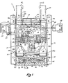
- Figure 1 is a plan view of the chair control;
- Figure 2 is a fragmentary cross-sectional view taken generally along planes II-II of Figure 1, showing only the right side seat support stretcher and back support arm (as viewed in Figure 1) and omitting the bias means 30, the
tension bolt assembly 40, the pneumaticcylinder adjustment assembly upright lock assembly - Figure 3 is the same view as Figure 2, but with the chair control in the position which it assumes when a person leans back in a chair to which the chair control is attached;
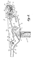
- Figure 4 is a side elevational view of the chair control with some of the internal components being shown in hidden lines;
- Figure 5 is a top plan view of the chair
seat supporting assembly 70; - Figure 6 is a side elevational view thereof;
- Figure 7 is a top plan view of the seat
adjustment pivot bracket 81; - Figure 8 is a cross-sectional view thereof taken along plane VIII-VIII of Figure 7;
- Figure 9 is a top plan view of the pivot bracket insert 86;
- Figure 10 is a cross-sectional view thereof taken along plane X-X of Figure 9;
- Figure 11 is a cross-sectional view thereof taken along plane XI-XI of Figure 9;
- Figure 12 is a cross-sectional view thereof taken along plane XII-XII of Figure 9;
- Figure 13 is a top plan view of the seat adjustment slide 90; and
- Figure 14 is a side elevational view thereof.
- The chair control 1 comprises a
stationary control housing 10 which houses a bias means 30 (Figures 1 and 4). The degree of pre-tension on the bias means 30 is controlled by atension bolt assembly 40. Chair back supportarms 60 are secured to the ends of anarbor 31 forming-part of the bias means 30 and pivot with respect to thestationary control housing 10. A chair seatsupport stretcher assembly 70 is pivotally mounted at its rear directly to theback support arms 60. The front of theseat support assembly 70 is slidably mounted withintracks 20 on the front of thestationary control housing 10. This slidable mount could be direct, but as shown in the preferred embodiment is through a seatedadjustment assembly 80. - The
stationary control housing 10 is a stamped metal dish having a bottom wall 11,side walls 12, afront wall 13 and rear wall 14 (Figures 2 and 3). Alip 15 extends around the upper periphery (see Figure 2). There is an aperture in the bottom wall 11 through which the upper end of aspindle assembly 2 extends. Aspindle mounting plate 16 is welded to the inside of thehousing 10 and includes anaperture 171 therein to also receive the upper end of the spindle assembly 2 (Figures 1 and 2). - Projecting forwardly from the-
front wall 13 are a pair of brackets forming thetracks 20. The brackets are formed of metal by bending them so as to define atop wall 21, abottom wall 22 and afront wall 23. These basically define the tracks in which theseat support assembly 70 is slidably mounted. Extending downwardly from thebottom wall 22 is afront brace 24 and extending from thefront brace 24 is abottom brace 25. The rear portion oftop wall 21, thefront brace 24 and thebottom brace 25 are welded to thestationary control housing 10 to hold the track brackets in place. - The bias means 30 comprises a torsional coil spring arrangement. The
arbor 31 which is generally circular in cross section extends through holes 17 in theside walls 12 of the stationary control housing 10 (compare to Figures 1 and 2). Thearbor 31 is actually hidden in Figure 1 since it is covered by aplastic sleeve 34. The ends of thearbor 31 are rotatably carried inend bearings 35 which are located within the side wall holes 17. Coiled around thearbor 31 andsleeve 34 are a pair ofcoil springs 32. The front ends 32a of thecoil springs 32 are captured under a retainer nut 59 forming part of thetension bolt assembly 40, being held between the side walls of notches in the retainer nut. The rear ends 32b of thesprings 32 are captured under the chair back supportarms 60. Tension adjustment is achieved by tightening or loosening the tension bolt of theassembly 40 in the retainer nut 59. As can be seen from Figure 4, thetension bolt assembly 40 comprises a bolt 40a having a hollow shank normally housing alever 47. One can grasp a gripping cap 51, retract thelever 47, pivot it to one side into a slot 43a and rotate it to move the bolt 40a up or down in the retainer 59. - The chair back
support arms 60 are formed of metal and are channel shaped having atop wall 63, aside wall 64 and a bottom wall 65 (Figure 2). There are two such chair back mountingarms 60, one located on either side of the stationary housing 10 (Figure 1). The generally channel-shape cross section allows one to slip a chair back support frame or arm into the channels. - The arbor mounting holes 61 in the
side wall 64 of one of the chair backsupport arms 60 are visible through the hole 17 in the side of thestationary housing 10 in Figure 2. The holes are two semi-circles 61 spaced by abridge 62. The ends of thearbor 30 are slotted so that they fit into the semi-circles 61. In this way, the chair backsupport arms 60 are fixed against rotation with respect to thearbor 30 and as one tilts back in the chair, the chair backsupport arms 60 pivot and thearbor 30 rotates within itsplastic end bearings 35. - On the
top wall 63 of eachsupport arm 60, and located toward the front thereof are a pair of downwardly projecting dimples or protrusions 69 (Figure 2). The rear end 32b of eachcoil spring 30 is captured betweendimples 69. The other protrusions shown projecting up from thetop wall 63 are merely reinforcing ribs. - Located about midway along the length of each chair back
support arm 60 is ahole 66 which is adapted to receive arear axle 68 and abearing 68a. It is on therear axle 68 that the rear of the chairseat support assembly 70 is pivotally carried. - The chair
seat support assembly 70 comprises a pair of spaced stretchers 70a joined at the front by a front piece 74 (Figures 1, 2, 5 and 6). Each side stretcher 70a is formed of steel to define a top ledge 71 and aside wall 72. There are mountingholes 76 in top ledges 71 to facilitate mounting the chair control 1 to the bottom of a chair seat. Located in one side stretcher 70a is apush rod hole 77 through which the push rod 105 of a pneumaticcylinder adjustment assembly 100 extends. There is an aperture 78a in the same side stretcher and asimilar aperture 78 in the other side stretcher 70a through which a chair controllock actuator rod 150 extends. - Located towards the rear of each
side wall 72 of each stretcher 70a is a rear axle receiving hole 79 (Figure 6) which receives the end of therear axle 68 carried in a suitable plastic bearing 79a of "T" shaped longitudinal cross section (Figure 1). Retainer clips 79b then hold therear axle 68 in position. - The
front piece 74 which is welded to the side stretchers 70a is generally "J" shaped having a bottom wall 74a, a front wall 74b and atop lip 74c. The bottom wall 74a includes a pair of spacedslots 75 for cooperating with components of theseat adjustment assembly 80. - A large generally
rectangular opening 73 is provided towards the front of eachside wall 72 of each stretcher 70a. (Figures 4 and 6). These facilitate sliding of anaxle 89 in thetracks 20 without interference and also facilitate cooperation with theseat adjustment assembly 80. Additional holes 73a in theside walls 72 of the stretchers 70a similarly facilitate mounting of theseat adjustment assembly 80 to thestretcher assembly 70. The details of this cooperation are set forth more fully hereinbelow. - At this point, it should be noted that the chair
support stretcher assembly 70 could be slidably mounted directly to thefront tracks 20 without incorporating theseat adjustment assembly 80 in any way. - The
seat adjustment assembly 80 comprises first of all apivot bracket 81 which is pivotally mounted between the side stretchers 70a of thestretcher assembly 70 via pivot nut, bolt andwasher assemblies 82 through holes 73a (Figures 1, 2, 7 and 8). Thepivot bracket 81 comprises a pair of spaced, short legs 81a joined by a cylindrical bottom wall 81b. Cylindrical wall 81b defines a portion of the wall of a right circular cylinder having its axis of revolution on the pivot axis betweenbracket 81 andseat support assembly 70. Towards the front of each side wall 81a there is a hole 82a through which the bolt of nut, bolt andwasher assembly 82 passes (Figure 8). - Referring to Figure 7, it will be seen that there are a pair of spaced
slots 83 in the bottom wall 81b of thepivot bracket 81. Eachslot 83 is generally spirally or helically oriented in the cylindrical bottom wall 81b. When thepivot bracket 81 is pivotally secured in position in the seatsupport stretcher assembly 70, thehelical slots 83 line up above theslots 75, with bottom wall 81b possibly but not necessarily contacting the bottom wall 74a of thefront piece 74 of theseat support assembly 70. However, theslots 83 are slanted relative to theslots 75 such that they overlap only at selected points at any given time. - The particular points at which the
slots 83 line up with theslots 75 is determined by an adjustment slide 90 (Figures 2, 4, 13 and 14) which comprises aflat bottom plate 91 having agripper flange 92 projecting downwardly from the bottom thereof. Protruding upwardly from thebottom plate 91 are a pair of spacedbolts 93. Thebottom plate 91 including thegripper 92 is moulded of plastic and thebolts 93 are square cross section shoulder bolts which are moulded in place in the plastic. A raised locatingshoulder 96 around eachbolt 93 is also integrally moulded of the plastic material with theplate 91 and thegripper 92. - In assembly, the
bolts 93 project upwardly through theslots shoulder 96 fitting snugly within one of theslots 75 in the bottom wall 74a of thefront piece 74 of theseat support assembly 70. Between theassembly 70 and thepivot bracket 81 there is a pair of moulded pivot bracket inserts 86 (Figures 9 to 12 as well as Figures 1, 2 and 4). The square cross sectionedshank 95 of eachbolt 93 extends upwardly through aslot 88 in one of theinserts 86. Theinserts 86 are made of-a self lubricating plastic such as a glass reinforced nylon in order to minimize friction in the seat adjustment assembly. It will be noted that each insert 86 is cylindrical in cross section so that it seats snugly against the cylindrical cross sectional configuration of the bottom wall 81b ofpivot bracket 81. Theslot 88 in eachpivot bracket insert 86 is helical so that it matches with theslots 83. It will be further noted that eachslot 88 is framed by a peripheral, downwardly projectinglip 87 which extends into one of theslots 83. The helical configuration of thelip 87 can be appreciated by reference to the three cross sections shown in Figures 10, 11 and 12. - It can be seen from Figure 13 that, because of the difference between the generally
rectilinear slots 75 in the seatsupport front piece 74 and thehelical slot 88 in each pivot bracket inserts 86, theplastic locating shoulders 96 at the base of each upwardly projectingbolt 93 are generally rectangular in configuration and are oriented parallel to the longitudinal axis of the seat adjustment slide 90. Thus, these locatingshoulders 96 sit nicely in theslots 75 and slide readily from one end thereof to the other. - However, the generally
rectangular shanks 95 of theshoulder bolts 93 are cocked at a slight angle with respect to the longitudinal axis of the slide 90. This is accomplished by embedding theshoulder bolts 93 at a cocked angle that can be seen from the outline of theheads 94 of the bolts which are embedded in the plastic ofbottom plate 91. These' cocked, generally rectangular shanks orshoulders 95 then fit readily into theslots 88 and slide readily along the length thereof. - Projecting upwardly from the cocked
shoulders 95 of thebolts 93 are threaded upper ends 95a. Referring to Figures 1, 2 and 4, it will be understood that awasher 97 of generally solid semi-cylindrical lateral cross section fits over the threaded portion 95a of eachbolt 93 and the cylindrical wall portion of eachwasher 97 seats down in the cylindrical nest defined by one of the pivot bracket inserts 86.Flanged nuts 98 are then threaded down on to the threaded ends 95a of thebolts 93. The components are dimensioned or adjusted such that thewasher 97 rests.on top of the shoulder orshank 95 without tightening the pivot bracket inserts 86 andpivot bracket 81 too tight against the bottom wall 74a of the seatstretcher front piece 74. This allows one to slide the seat adjustment slide 90 to the left or to the right relative to the front of the chair control 1, thereby changing that portion of theslots slots 75 of the seatstretcher front piece 74. In effect, this causes thepivot bracket 81 to rotate about its pivotal mounting via the nut, washer andbolt assemblies 82 to theseat stretcher assembly 70. Such rotation shifts the elevation of the left end of each leg 81a of thepivot bracket 81 with respect to the side stretchers 70a of theseat stretcher assembly 70. - The purpose of this change in elevation is to change the effective angle or elevation of the front of a chair seat mounted on the chair control 1. Located at the left end, as viewed in Figures 2, 4 and 8, of the
pivot bracket 81 is anaxle receiving hole 84. Thefront slide axle 89 extends through theaxle receiving holes 84 in the opposite pivot bracket legs 81a. The ends of theaxle 89 are carried in bearings 89a. - The
axle 89 passes through the lateral openings in thetrack brackets 20 at the front of thestationary control housing 10 whereby thepivot bracket 81 is pivotally mounted to thestationary housing 10. Within the confines of eachtrack bracket 20, theaxle 89 is carried in aplastic bushing 99 of generally rectangular cross section (Figures 1 and 2). Retainer clips or rings 99a (Figure 1) hold theplastic bushing 99 and theaxle 89 in position within thetrack bracket 20. With the ends of pivot bracket legs 81a thus assembled to the front of thestationary control housing 10, the pivoting of thepivot bracket 81 by changing the position of the slide 90 thereby changes the elevation of the front of theseat support assembly 70 with respect to the front of thestationary control housing 10. This then facilitates adjustment of the seat angle by the user of the chair to which the chair control 1 is mounted. - The
bushings 99 are preferably formed of a self lubricating plastic material such as a plastic of the acetal type, for example that available from Dupont under the Trade Mark "DELRIN" or that from Celenese under the Trade Mark "CELCON". This enables thebushings 99 to slide along the length of thetrack brackets 20. - Such sliding action takes place when the user of a chair to which the chair control 1 is mounted leans back in the chair. In leaning back, he causes the chair back support arms 60.to pivot about their pivot point with respect to the
stationary housing 10. Similarly, the chairseat support assembly 70 tilts rearwardly since it is pivotally connected directly to theback support arms 60 at therear axle 68. At the same time, thefront axle 89 and thebushings 99 slide rearwardly within thetrack brackets 20. Theenlarged openings 73 in the side stretchers 70a allow clearance for the ends of theaxle 89 to move up and down and slide. A comparison of chair control 1 in its untilted and tilted back positions respectively can be seen by comparing Figures 2 and 3. - Also, the sliding interconnection between the
stationary housing 10 and thepivot axle 89 allows thepivot axle 89 to shift as thepivot bracket 81 is rotated. At some-point, there has to be means allowing at least one connection between thehousing 10 to shift vis-a-vis theseat support 70 when thesupport bracket 81 is rotated. - With the various assemblies, sub assemblies and components thus described, the operation of the chair control 1 can be more fully appreciated. As a person leans back in a chair to which chair control 1 is assembled, the chair back
support arms 60 begin to pivot about their pivotal mounting (on arbor 31) to thestationary housing 10. At the same time the rear of the seatsupport stretcher assembly 70 begins to shift downwardly relative to its front since the chair seatsupport stretcher assembly 70 is pivotally joined to theback support arms 60 by therear axle 68. The front of theseat support assembly 70 pivots about thefront axle 89 which, along with itsbushings 99, slides rearwardly in thetracks 20. Figures 2 and 3 illustrate the chair control 1 in its untilted and fully tilted conditions respectively, - The. various pivot points are located such that the chair back tilts rearwardly at a rate which is approximately twice as fast as the rate of tilt for the- seat. Because the
seat support 70 is pivotally connected directly to theback support arms 60 rather than through some sort of toggle linkage or slide, there is less sensation of the seat and back separating as one tilts rearwardly. Further, wear and tear are minimized since the only movement between theseat support 70 and backsupport 60 is a pivotal movement about suitable bearings. The loads imposed on the slidingbushings 99 are relatively minimal compared to the loads imposed on therear axle 68. That is because as one tips rearwardly in the chair, one tends to shift one's weight to the rear of the chair and off the front of the chair seat. As a result, there is little likelihood of thebushings 99 getting jammed in thetracks 20 or of wearing out before they have enjoyed a suitable life span.
Claims (6)
Applications Claiming Priority (5)
| Application Number | Priority Date | Filing Date | Title |
|---|---|---|---|
| US06/145,624 US4375301A (en) | 1980-05-01 | 1980-05-01 | Chair seat adjustment assembly |
| US06/145,622 US4438898A (en) | 1980-05-01 | 1980-05-01 | Chain control locking assembly |
| US06/145,439 US4314728A (en) | 1980-05-01 | 1980-05-01 | Chair control |
| US06/145,854 US4390206A (en) | 1980-05-01 | 1980-05-01 | Synchrotilt chair control |
| US145439 | 1993-10-29 |
Publications (3)
| Publication Number | Publication Date |
|---|---|
| EP0039574A2 true EP0039574A2 (en) | 1981-11-11 |
| EP0039574A3 EP0039574A3 (en) | 1982-06-23 |
| EP0039574B1 EP0039574B1 (en) | 1985-11-06 |
Family
ID=42246360
Family Applications (2)
| Application Number | Title | Priority Date | Filing Date |
|---|---|---|---|
| EP19810301890 Expired EP0039574B1 (en) | 1980-05-01 | 1981-04-29 | Chair control |
| EP19810301892 Expired EP0039576B1 (en) | 1980-05-01 | 1981-04-29 | Chair seat adjustment assembly |
Family Applications After (1)
| Application Number | Title | Priority Date | Filing Date |
|---|---|---|---|
| EP19810301892 Expired EP0039576B1 (en) | 1980-05-01 | 1981-04-29 | Chair seat adjustment assembly |
Country Status (5)
| Country | Link |
|---|---|
| US (4) | US4314728A (en) |
| EP (2) | EP0039574B1 (en) |
| CA (4) | CA1162832A (en) |
| DE (2) | DE3172578D1 (en) |
| ES (2) | ES501794A0 (en) |
Cited By (1)
| Publication number | Priority date | Publication date | Assignee | Title |
|---|---|---|---|---|
| DE4100641A1 (en) * | 1991-01-11 | 1992-07-16 | Kloeber Gmbh & Co | Office chair with synchronised reclining adjustment - has two shank springs mounted on support tube at front |
Families Citing this family (65)
| Publication number | Priority date | Publication date | Assignee | Title |
|---|---|---|---|---|
| DE8133573U1 (en) * | 1981-11-17 | 1983-05-05 | Fritz Bauer + Söhne oHG, 8503 Altdorf | LOCKABLE LOCKING DEVICE FOR SEAT PARTS OF SEAT FURNITURE |
| US4494795A (en) * | 1982-05-06 | 1985-01-22 | Steelcase Inc. | Variable back adjuster for chairs |
| JPS59207112A (en) * | 1983-05-10 | 1984-11-24 | メ−コ−工業株式会社 | Chair |
| DE3335463A1 (en) * | 1983-09-30 | 1985-04-11 | Fritz Bauer + Söhne oHG, 8503 Altdorf | CARRYING DEVICE FOR SEAT FURNITURE WITH ADJUSTABLE BACKREST SUPPORT AND ADJUSTABLE SEAT |
| DE8401000U1 (en) * | 1984-01-14 | 1984-04-05 | Mauser Waldeck AG, 3544 Waldeck | SWIVEL CHAIR |
| DE3521488A1 (en) * | 1985-06-14 | 1986-12-18 | August Fröscher GmbH & Co KG, 7141 Steinheim | WORK CHAIR |
| IT1202168B (en) * | 1985-07-18 | 1989-02-02 | Coop Operai Mobilieri | ANATOMICAL ARMCHAIR |
| SE461312B (en) * | 1986-02-19 | 1990-02-05 | Swing Matic Ab | SWING MECHANISM WITH ARRANGEMENT |
| US5567012A (en) * | 1986-04-10 | 1996-10-22 | Steelcase, Inc. | Chair control |
| US4776633A (en) * | 1986-04-10 | 1988-10-11 | Steelcase Inc. | Integrated chair and control |
| IT206947Z2 (en) * | 1986-06-12 | 1987-10-26 | Pro Cord Srl | CHAIR WITH ARTICULATED BACKREST |
| US4718726A (en) * | 1987-07-07 | 1988-01-12 | Estkowski Michael H | Chair seat tilt control |
| US4889384A (en) * | 1988-07-10 | 1989-12-26 | Leggett & Platt, Incorporated | Knee-action chair control |
| US4948198A (en) * | 1988-10-14 | 1990-08-14 | Leggett & Platt, Incorporated | Knee-tilt chair control |
| US4979778A (en) * | 1989-01-17 | 1990-12-25 | Brayton International, Inc. | Synchrotilt chair |
| US5106157A (en) * | 1989-03-01 | 1992-04-21 | Herman Miller, Inc. | Chair height and tilt adjustment mechanisms |
| US4892354A (en) * | 1989-06-30 | 1990-01-09 | Shepherd Products U.S., Inc. | Chair seat tilt control |
| US5029940A (en) * | 1990-01-16 | 1991-07-09 | Westinghouse Electric Corporation | Chair tilt and chair height control apparatus |
| US5257767A (en) | 1990-06-13 | 1993-11-02 | Waterloo Furniture Components, Ltd. | Adjustable support mechanism for a keyboard platform |
| US5318346A (en) * | 1991-05-30 | 1994-06-07 | Steelcase Inc. | Chair with zero front rise control |
| US5318345A (en) * | 1991-06-07 | 1994-06-07 | Hon Industries, Inc. | Tilt back chair and control |
| US5203853A (en) * | 1991-09-18 | 1993-04-20 | Herman Miller, Inc. | Locking chair tilt mechanism with torsion bar |
| US5328242A (en) * | 1992-03-18 | 1994-07-12 | Steelcase Inc. | Chair with back lock |
| US5282670A (en) * | 1992-04-20 | 1994-02-01 | Steelcase Inc. | Cable actuated variable stop mechanism |
| CA2136967C (en) * | 1992-06-15 | 2001-04-03 | William E. Stumpf | Office chair |
| CH690019A5 (en) * | 1992-07-16 | 2000-03-31 | Giroflex Entwicklungs Ag | Supporting frame for a chair, in particular for an adjustable in height and tilt office chair. |
| US5356200A (en) * | 1992-10-23 | 1994-10-18 | Doerner Products Ltd. | Unitary brake for a chair tilt mechanism |
| US5630643A (en) * | 1993-06-01 | 1997-05-20 | Steelcase Inc | Upholstered chair with two-piece shell |
| US5427434A (en) * | 1993-07-30 | 1995-06-27 | Leggett & Platt, Incorporated | Chair tilt and height adjustment mechanism |
| US5577807A (en) * | 1994-06-09 | 1996-11-26 | Steelcase Inc. | Adjustable chair actuator |
| EP0763991A4 (en) * | 1994-06-10 | 2000-10-04 | Haworth Inc | Ergonomic chair |
| US5782536A (en) * | 1995-02-17 | 1998-07-21 | Steelcase Inc. | Modular chair construction and method of assembly |
| US5765914A (en) * | 1995-06-07 | 1998-06-16 | Herman Miller, Inc. | Chair with a tilt control mechanism |
| US5810439A (en) * | 1996-05-09 | 1998-09-22 | Haworth, Inc. | Forward-rearward tilt control for chair |
| US5755214A (en) * | 1996-11-12 | 1998-05-26 | Ming-Jeong Lin | Ventilator hood for a cooker |
| US5909924A (en) * | 1997-04-30 | 1999-06-08 | Haworth, Inc. | Tilt control for chair |
| US6086153A (en) * | 1997-10-24 | 2000-07-11 | Steelcase Inc. | Chair with reclineable back and adjustable energy mechanism |
| US6250715B1 (en) | 1998-01-21 | 2001-06-26 | Herman Miller, Inc. | Chair |
| AU783829B2 (en) | 2000-09-28 | 2005-12-08 | Formway Furniture Limited | A reclinable chair |
| USD445580S1 (en) | 2000-09-28 | 2001-07-31 | Formway Furniture Limited | Chair |
| USD463144S1 (en) | 2000-09-28 | 2002-09-24 | Formway Furniture Limited | Chair |
| AUPR054400A0 (en) | 2000-09-29 | 2000-10-26 | Formway Furniture Limited | A castor |
| US6585320B2 (en) | 2001-06-15 | 2003-07-01 | Virco Mgmt. Corporation | Tilt control mechanism for a tilt back chair |
| US6644741B2 (en) | 2001-09-20 | 2003-11-11 | Haworth, Inc. | Chair |
| US7625046B2 (en) * | 2002-03-29 | 2009-12-01 | Garrex Llc | Task chair |
| US20050046258A1 (en) * | 2003-07-09 | 2005-03-03 | Sanchez Gary L. | Task chair |
| US7040703B2 (en) * | 2002-03-29 | 2006-05-09 | Garrex Llc | Health chair a dynamically balanced task chair |
| US7396082B2 (en) | 2002-03-29 | 2008-07-08 | Garrex Llc | Task chair |
| NZ518944A (en) | 2002-05-14 | 2004-09-24 | Formway Furniture Ltd | Height adjustable arm for chair with outer stem releasably lockable to inner stem by engagement of recesses |
| US6880886B2 (en) * | 2002-09-12 | 2005-04-19 | Steelcase Development Corporation | Combined tension and back stop function for seating unit |
| US6793284B1 (en) * | 2003-03-19 | 2004-09-21 | L & P Property Management Company | Steel spring with dwell for chairs |
| US6945602B2 (en) * | 2003-12-18 | 2005-09-20 | Haworth, Inc. | Tilt control mechanism for chair |
| US7237841B2 (en) * | 2004-06-10 | 2007-07-03 | Steelcase Development Corporation | Back construction with flexible lumbar |
| US7458637B2 (en) * | 2004-06-10 | 2008-12-02 | Steelcase Inc. | Back construction with flexible lumbar |
| CN101137307B (en) * | 2005-03-01 | 2013-05-29 | 霍沃思公司 | Tension adjustment mechanism for a chair |
| CN102151027B (en) | 2007-01-29 | 2016-03-16 | 赫尔曼米勒有限公司 | Seat structure and using method thereof |
| ITMI20070718A1 (en) * | 2007-04-06 | 2008-10-07 | L & P Property Management Co | ADJUSTMENT DEVICE FOR ADJUSTABLE AND SIMILAR CHAIRS. |
| ITMI20070719A1 (en) * | 2007-04-06 | 2008-10-07 | L & P Property Management Co | TILTING DEVICE FOR A RECLINING SEAT. |
| US8876209B2 (en) | 2008-05-26 | 2014-11-04 | Steelcase Inc. | Conforming back for a seating unit |
| EP2347676B1 (en) * | 2010-01-22 | 2012-08-22 | Stoll Giroflex AG | Support structure for a back part and/or the seat of a sitting device and sitting device with such a support structure |
| TW201216901A (en) * | 2010-10-28 | 2012-05-01 | Chia Chi Ya Entpr Co Ltd | with position-limiting function between fixed frame and pivotal frame to avoid an excessive rotation of the backrest and the injury of hands |
| US11229294B2 (en) * | 2012-09-20 | 2022-01-25 | Steelcase Inc. | Chair assembly with upholstery covering |
| USD696545S1 (en) | 2013-07-30 | 2013-12-31 | Steelcase, Inc. | Rear surface of a chair back |
| US11589678B2 (en) | 2019-01-17 | 2023-02-28 | Hni Technologies Inc. | Chairs including flexible frames |
| SE544527C2 (en) * | 2019-01-18 | 2022-07-05 | Flokk Ab | A tilt locking device for a chair seat |
Citations (1)
| Publication number | Priority date | Publication date | Assignee | Title |
|---|---|---|---|---|
| US2961035A (en) * | 1954-05-26 | 1960-11-22 | Lorenz Anton | Article of repose for supporting the body of a person |
Family Cites Families (23)
| Publication number | Priority date | Publication date | Assignee | Title |
|---|---|---|---|---|
| US178720A (en) * | 1876-06-13 | Improvement in recliwng-chairs | ||
| US1415252A (en) * | 1918-07-31 | 1922-05-09 | John V Mcmanis | Treatment stool |
| US1674846A (en) * | 1925-09-19 | 1928-06-26 | Carl F Streit | Chair |
| US2321385A (en) * | 1941-06-16 | 1943-06-08 | Sikes Company | Tilting chair |
| US2572444A (en) * | 1946-06-21 | 1951-10-23 | Carden Albert | Tool handle |
| US2471024A (en) * | 1946-10-04 | 1949-05-24 | Roy A Cramer | Chair with tilting back and automatically shiftable seat |
| US2627299A (en) * | 1947-12-03 | 1953-02-03 | Edward M Martin | Adjustable bus seat |
| US2638150A (en) * | 1951-02-07 | 1953-05-12 | Checker Cab Mfg Corp | Adjustable seat structure |
| GB815779A (en) * | 1957-03-21 | 1959-07-01 | Finn Lie | Tilting mechanism for seat furniture |
| US2956619A (en) * | 1958-10-03 | 1960-10-18 | Cramer Posture Chair Company I | Tilt back chair |
| US3072436A (en) * | 1960-04-14 | 1963-01-08 | Moore Edwin Rosco | Tilting devices for chair seats and chair backs |
| BE669160A (en) * | 1964-09-03 | 1965-12-31 | ||
| US3480249A (en) * | 1967-12-11 | 1969-11-25 | Finn Lie | Tilting chair construction |
| US3627252A (en) * | 1969-12-22 | 1971-12-14 | Yoshiomi Yamaguchi | Tilting chair |
| GB1343305A (en) * | 1971-04-01 | 1974-01-10 | Werner P G | Adjustable resiliently hinged device for chairs and the like |
| US3758157A (en) * | 1971-09-20 | 1973-09-11 | Steelcase Inc | Chair |
| US3881772A (en) * | 1973-10-03 | 1975-05-06 | Stewart Warner Corp | Chair control mechanism |
| DE2623024A1 (en) * | 1976-05-22 | 1977-12-08 | Wilkhahn Wilkening & Hahne | SEATING FURNITURE, IN PARTICULAR CHAIR WITH SEAT PART |
| US4099775A (en) * | 1976-10-07 | 1978-07-11 | Hoover Ball And Bearing Company | Chair control with tilt lock |
| DE2801168C2 (en) * | 1978-01-12 | 1986-09-25 | Keiper Recaro GmbH & Co, 7312 Kirchheim | Adjusting device, in particular for a headrest of a vehicle seat |
| US4154477A (en) * | 1978-03-20 | 1979-05-15 | Milsco Manufacturing Company | Vehicle seat having backrest height adjustment means |
| US4155593A (en) * | 1978-03-20 | 1979-05-22 | Milsco Manufacturing Company | Vehicle seat having seat rake adjustment means |
| US4214726A (en) * | 1978-11-06 | 1980-07-29 | Steelcase, Inc. | Chair control |
-
1980
- 1980-05-01 US US06/145,439 patent/US4314728A/en not_active Expired - Lifetime
- 1980-05-01 US US06/145,624 patent/US4375301A/en not_active Expired - Lifetime
- 1980-05-01 US US06/145,622 patent/US4438898A/en not_active Expired - Lifetime
- 1980-05-01 US US06/145,854 patent/US4390206A/en not_active Expired - Lifetime
-
1981
- 1981-04-21 CA CA000375846A patent/CA1162832A/en not_active Expired
- 1981-04-21 CA CA000375862A patent/CA1162833A/en not_active Expired
- 1981-04-21 CA CA000375774A patent/CA1156922A/en not_active Expired
- 1981-04-24 CA CA000376139A patent/CA1157366A/en not_active Expired
- 1981-04-29 DE DE8181301892T patent/DE3172578D1/en not_active Expired
- 1981-04-29 EP EP19810301890 patent/EP0039574B1/en not_active Expired
- 1981-04-29 DE DE8181301890T patent/DE3172808D1/en not_active Expired
- 1981-04-29 EP EP19810301892 patent/EP0039576B1/en not_active Expired
- 1981-04-30 ES ES501794A patent/ES501794A0/en active Granted
- 1981-04-30 ES ES501793A patent/ES501793A0/en active Granted
Patent Citations (1)
| Publication number | Priority date | Publication date | Assignee | Title |
|---|---|---|---|---|
| US2961035A (en) * | 1954-05-26 | 1960-11-22 | Lorenz Anton | Article of repose for supporting the body of a person |
Cited By (1)
| Publication number | Priority date | Publication date | Assignee | Title |
|---|---|---|---|---|
| DE4100641A1 (en) * | 1991-01-11 | 1992-07-16 | Kloeber Gmbh & Co | Office chair with synchronised reclining adjustment - has two shank springs mounted on support tube at front |
Also Published As
| Publication number | Publication date |
|---|---|
| CA1156922A (en) | 1983-11-15 |
| ES8207420A1 (en) | 1982-09-16 |
| ES8205548A1 (en) | 1982-06-16 |
| EP0039574B1 (en) | 1985-11-06 |
| CA1157366A (en) | 1983-11-22 |
| EP0039576A3 (en) | 1982-06-16 |
| CA1162832A (en) | 1984-02-28 |
| DE3172808D1 (en) | 1985-12-12 |
| US4375301A (en) | 1983-03-01 |
| EP0039574A3 (en) | 1982-06-23 |
| EP0039576B1 (en) | 1985-10-09 |
| ES501794A0 (en) | 1982-09-16 |
| US4390206A (en) | 1983-06-28 |
| EP0039576A2 (en) | 1981-11-11 |
| CA1162833A (en) | 1984-02-28 |
| DE3172578D1 (en) | 1985-11-14 |
| ES501793A0 (en) | 1982-06-16 |
| US4438898A (en) | 1984-03-27 |
| US4314728A (en) | 1982-02-09 |
Similar Documents
| Publication | Publication Date | Title |
|---|---|---|
| EP0039574A2 (en) | Chair control | |
| US4373692A (en) | Chair control with height adjustment actuator | |
| US6793284B1 (en) | Steel spring with dwell for chairs | |
| US4521053A (en) | Chair | |
| US5909924A (en) | Tilt control for chair | |
| US5464274A (en) | Chair seat tilt adjustment and locking mechanism | |
| US6827401B2 (en) | Leaf spring rocker mechanism for a reclining chair | |
| US6109694A (en) | Chair with four-bar linkage for self-adjusting back tension | |
| CA1315662C (en) | Synchrotilt chair | |
| US5547252A (en) | Office chair | |
| US4752101A (en) | Tilt control arrangement for office furniture chair | |
| KR920700571A (en) | Ergonomic chair | |
| JPH03109009A (en) | Supporting device for chair capable of inclination | |
| US4938532A (en) | Seating apparatus | |
| EP0987970A1 (en) | Chairback with side torsional movement | |
| US4858993A (en) | Work chair comprising a swivelling seat shell | |
| US20030178876A1 (en) | Multi-task mid-pivot chair control mechanism | |
| US5388889A (en) | Torque control mechanism for chairs | |
| JP4727805B2 (en) | Control lever structure in a chair | |
| EP0131553A2 (en) | Chair | |
| NO169086B (en) | FLOORING AND WALL COATING, AND PROCEDURE FOR PREPARING DISS | |
| JP4754679B2 (en) | Tilt range adjustment device for backrest in chair | |
| JPH052122Y2 (en) | ||
| JP4818506B2 (en) | Tilt device for backrest in chair | |
| EP1097660B1 (en) | A sliding blocking device for varying and regulating the position of chair structures and/or their parts |
Legal Events
| Date | Code | Title | Description |
|---|---|---|---|
| PUAI | Public reference made under article 153(3) epc to a published international application that has entered the european phase |
Free format text: ORIGINAL CODE: 0009012 |
|
| AK | Designated contracting states |
Designated state(s): DE FR GB |
|
| PUAL | Search report despatched |
Free format text: ORIGINAL CODE: 0009013 |
|
| AK | Designated contracting states |
Designated state(s): DE FR GB |
|
| 17P | Request for examination filed |
Effective date: 19821124 |
|
| GRAA | (expected) grant |
Free format text: ORIGINAL CODE: 0009210 |
|
| AK | Designated contracting states |
Designated state(s): DE FR GB |
|
| REF | Corresponds to: |
Ref document number: 3172808 Country of ref document: DE Date of ref document: 19851212 |
|
| ET | Fr: translation filed | ||
| PLBE | No opposition filed within time limit |
Free format text: ORIGINAL CODE: 0009261 |
|
| STAA | Information on the status of an ep patent application or granted ep patent |
Free format text: STATUS: NO OPPOSITION FILED WITHIN TIME LIMIT |
|
| 26N | No opposition filed | ||
| PGFP | Annual fee paid to national office [announced via postgrant information from national office to epo] |
Ref country code: GB Payment date: 19930319 Year of fee payment: 13 |
|
| PGFP | Annual fee paid to national office [announced via postgrant information from national office to epo] |
Ref country code: FR Payment date: 19930412 Year of fee payment: 13 |
|
| PGFP | Annual fee paid to national office [announced via postgrant information from national office to epo] |
Ref country code: DE Payment date: 19930428 Year of fee payment: 13 |
|
| PG25 | Lapsed in a contracting state [announced via postgrant information from national office to epo] |
Ref country code: GB Effective date: 19940429 |
|
| PG25 | Lapsed in a contracting state [announced via postgrant information from national office to epo] |
Ref country code: FR Effective date: 19941229 |
|
| PG25 | Lapsed in a contracting state [announced via postgrant information from national office to epo] |
Ref country code: DE Effective date: 19950103 |
|
| GBPC | Gb: european patent ceased through non-payment of renewal fee |
Effective date: 19940429 |
|
| REG | Reference to a national code |
Ref country code: FR Ref legal event code: ST |