EP0039694B1 - Fahrzeug mit kehrmaschine, insbesondere zum einholen von staubförmigen material und deren verwendung - Google Patents
Fahrzeug mit kehrmaschine, insbesondere zum einholen von staubförmigen material und deren verwendung Download PDFInfo
- Publication number
- EP0039694B1 EP0039694B1 EP80902049A EP80902049A EP0039694B1 EP 0039694 B1 EP0039694 B1 EP 0039694B1 EP 80902049 A EP80902049 A EP 80902049A EP 80902049 A EP80902049 A EP 80902049A EP 0039694 B1 EP0039694 B1 EP 0039694B1
- Authority
- EP
- European Patent Office
- Prior art keywords
- separator
- conduit
- piece
- suction
- air
- Prior art date
- Legal status (The legal status is an assumption and is not a legal conclusion. Google has not performed a legal analysis and makes no representation as to the accuracy of the status listed.)
- Expired
Links
Images


Classifications
-
- A—HUMAN NECESSITIES
- A47—FURNITURE; DOMESTIC ARTICLES OR APPLIANCES; COFFEE MILLS; SPICE MILLS; SUCTION CLEANERS IN GENERAL
- A47L—DOMESTIC WASHING OR CLEANING; SUCTION CLEANERS IN GENERAL
- A47L11/00—Machines for cleaning floors, carpets, furniture, walls, or wall coverings
- A47L11/40—Parts or details of machines not provided for in groups A47L11/02 - A47L11/38, or not restricted to one of these groups, e.g. handles, arrangements of switches, skirts, buffers, levers
-
- A—HUMAN NECESSITIES
- A47—FURNITURE; DOMESTIC ARTICLES OR APPLIANCES; COFFEE MILLS; SPICE MILLS; SUCTION CLEANERS IN GENERAL
- A47L—DOMESTIC WASHING OR CLEANING; SUCTION CLEANERS IN GENERAL
- A47L11/00—Machines for cleaning floors, carpets, furniture, walls, or wall coverings
- A47L11/24—Floor-sweeping machines, motor-driven
-
- A—HUMAN NECESSITIES
- A47—FURNITURE; DOMESTIC ARTICLES OR APPLIANCES; COFFEE MILLS; SPICE MILLS; SUCTION CLEANERS IN GENERAL
- A47L—DOMESTIC WASHING OR CLEANING; SUCTION CLEANERS IN GENERAL
- A47L9/00—Details or accessories of suction cleaners, e.g. mechanical means for controlling the suction or for effecting pulsating action; Storing devices specially adapted to suction cleaners or parts thereof; Carrying-vehicles specially adapted for suction cleaners
- A47L9/02—Nozzles
- A47L9/08—Nozzles with means adapted for blowing
-
- E—FIXED CONSTRUCTIONS
- E01—CONSTRUCTION OF ROADS, RAILWAYS, OR BRIDGES
- E01H—STREET CLEANING; CLEANING OF PERMANENT WAYS; CLEANING BEACHES; DISPERSING OR PREVENTING FOG IN GENERAL CLEANING STREET OR RAILWAY FURNITURE OR TUNNEL WALLS
- E01H1/00—Removing undesirable matter from roads or like surfaces, with or without moistening of the surface
- E01H1/08—Pneumatically dislodging or taking-up undesirable matter or small objects; Drying by heat only or by streams of gas; Cleaning by projecting abrasive particles
- E01H1/0827—Dislodging by suction; Mechanical dislodging-cleaning apparatus with independent or dependent exhaust, e.g. dislodging-sweeping machines with independent suction nozzles ; Mechanical loosening devices working under vacuum
- E01H1/0836—Apparatus dislodging all of the dirt by suction ; Suction nozzles
- E01H1/0845—Apparatus dislodging all of the dirt by suction ; Suction nozzles with mechanical loosening or feeding instruments for the dirt to be sucked- up, e.g. brushes, scrapers
Definitions
- the present invention relates to a vehicle with a sweeper, in particular for collecting dusty material.
- a cleaning device which is particularly suitable for cleaning streets and runways at airports.
- This device has a sensor with two sensor nozzles, the mutual position of which is rigid.
- the coarse fractions taken up are discharged into a cuboid chamber, in which, as the deposited material rises, the air passing through has increasing speeds and therefore not only does the air resistance in the chamber increase, but in particular the degree of separation deteriorates. This condition cannot be improved even by downstream screens and extraction of a partial air flow with recirculation into the chamber.
- Several, extremely complex, horizontally arranged, parallel centrifugal separators can not take advantage of the weight of the particles for the final separation of air and particles.
- a suction device for dust, chips, rubbish and other waste has a sensor in the form of a laterally rounded cuboid chamber, from the center of which a slot-shaped suction nozzle with a line leads to a first centrifugal separator.
- a slot blow nozzle opens out of the lid into the chamber.
- a blower between the blowing nozzles and the cyclone, whereby from the nozzle line - i.e. from the pressure line from the blower - a branch line with a fine separator and control valve branches off.
- this suction device is very simple, but it is hardly sufficient in terms of its effectiveness for fine dust; because there is only one nozzle in the sensor.
- the air distribution in the recirculating air and exhaust air is too immobile, since the recirculating air is only indirect and not inevitable - e.g. by means of another fan - is changeable.
- This suction device is therefore unsuitable because it is not effective enough to solve the problem at hand (FR-PS 1 057 157)
- the object of the present invention is to provide a sweeper, in particular for collecting metal dusts, which is simple in construction, has low pressure losses in the transport air due to good line routing, can be easily adapted to the specific dusts and can be accommodated as an assembly in the most confined space.
- this task can be carried out with the vehicle according to the invention with a sweeper.
- Fig. 1 shows the circuit diagram of a system 1 for receiving aluminum dust, with the pneumatic and the separation system.
- a main blower 3 is provided with a pressure port 4, which is divided into a main duct 6 and a secondary duct 7.
- the conveying air is divided by means of a flap 8 which can be pivoted about the axis 5 and which can be adjusted manually via a linkage or by means of a servomotor.
- the main channel 6 opens into a main mouthpiece 9 and supplies a side ring nozzle 10 - there may also be several nozzles extending over at least part of the circumference - with compressed air which blows the dust present against the center of the main mouthpiece 9.
- a main pipe 12 with a suction nozzle 13 (arranged in the middle or off-center) sucks off the air laden with aluminum dust.
- a secondary nozzle 15 is provided with a funnel 16 and a suction channel 19, which is designed to be movable, for example as a tube.
- the suction duct 17 and the main suction pipe 12 merge into a common duct 19, an adjustment flap 20 being arranged in the union in order to make the air quantities correspondingly adjustable.
- the community channel 19 continues in a cyclone inlet piece 22. In this there is a rotating, for example motor-driven, separation paddle wheel 23.
- the coarse particles are emptied through the channel 27, while the fine particles which are separated out in the multiclon are collected in the collecting bunker 26 and discharged from there.
- the three cyclones are in a collecting bunker 28.
- the central suction pipes 30, 31 and 32 of the cyclones 24, 25 and 26 open into a cyclone discharge piece 34 which merges into a blower suction line 35 which leads into the suction port of the blower 3.
- the secondary duct 7 leads to a bag filter 38 with a chamber 39 and an outlet 40.
- filter bags 41 are known to be hung next to one another and, if appropriate, one behind the other.
- the resulting fine powder is discharged at the outlet 40, while the exhaust air leads through an exhaust air duct 43 into an exhaust air blower 45, which blows the air, which has been practically cleaned of aluminum dust, into the atmosphere.
- the bag filter 38 no further details are disclosed about the bag filter 38, such as, for example, the automatic cleaning by shaking the filter bags, their replacement, the use of the corresponding tissue, etc. - since these are part of the prior art.
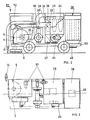
- FIG. 5 shows a four-wheel vehicle 50 with a driver's cab 52 and a bridge 53 on which the blower 3, the main mouthpiece 9 and the secondary nozzle 15 can be seen.
- the collecting bunker 28 with the cyclones is shown schematically, as well as the bag filter 38 with the filter bags inside, the entire four-wheel vehicle 50 with the driver's cab 52 and the bridge 53.
- a drive group 55 which can also be seen in FIGS. 2-4, drawn with auxiliary units 57.
- the secondary nozzle 15 is due to the movable suction channel 17 - e.g. in the form of a tube - arranged to be displaceable, the normal working position in FIG. 5 with a solid line, for sweeping niches with dashed lines and the cleaning position of raised heels, e.g. Oven borders are drawn with dash-dotted lines.
- a sweeper built on this principle according to FIGS. 1-5 is capable of picking up the finest aluminum dust, separating it and thus trapping it without blowing it out into the atmosphere at another point.
- Fine dust In addition to aluminum dust, other fine dusts such as Cement and the like. Fine dust can be obtained.
Description
- Die vorliegende Erfindung betrifft ein Fahrzeug mit Kehrmaschine, insbesondere zum Einholen von staubförmigem Material.
- Es ist ein Reinigungsgerät bekannt geworden, welches sich insbesondere zum Reinigen von Strassen und Landebahnen von Flughäfen eignet. Dieses Gerät hat einen Aufnehmer mit zwei Aufnehmerdüsen, deren gegenseitige Lage starr ist. Die aufgenommenen Grobanteile gelangen zur Ausscheidung in einer quaderförmigen Kammer, in welcher mit steigendem abgelagertem Material die durchstreichende Luft wachsende Geschwindigkeiten aufweist und daher nicht nur der Luftwiderstand in der Kammer wächst, sondern insbesondere der Abscheidungsgrad schlechter wird. Dieser Zustand kann auch durch nachgeschaltete Siebe und Abzug eines Teilluftstromes mit Rückführung in die Kammer nicht verbessert werden. Mehrere, im Aufbau äusserst komplizierte, horizontal angeordnete, parallel geschaltete Fliehkraftabscheider können sich das Eigengewicht der Teilchen zum endgültigen Trennen von Luft und Teilchen nicht zu Nutze machen. Das ungezügelte führungslose Ausströmen der Abluftströme aus den Zyklonen in und durch eine längliche Kammer und die durch keine Wände in ein Sauggebläse zweimal brüsk um je 90° umgelenkte Abluft tragen zur Verringerung der Strömungsverluste und der Leistungsverminderung des Antriebs wenig bei. Dieses Reinigungsgerät ist wegen seines komplizierten Aufbaus in jeder Beziehung unwirtschaftlich (DE-OS 1 924 054).
- Eine weitere Ausführungsart eines Sauggerätes für Staub, Späne, Kehricht und andere Abfälle, weist einen Aufnehmer in Form einer seitlich abgerundeten quaderförmigen Kammer auf, aus deren Deckelmitte eine schlitzförmige Saugdüse mit Leitung zu einem ersten Fliehkraftabscheider führt.
- Vorn und hinten in der Kammer mündet je eine Schlitz-Blasdüse aus dem Deckel in die Kammer. Zwischen Blasdüsen und Zyklon befindet sich ein Gebläse, wobei von der Düsenleitung - d.h. von der Druckleitung vom Gebläse - eine Zweigleitung mit einem Feinabscheider und Regelventil abzweigt.
- Dieses Sauggerät ist zwar im Aufbau sehr einfach, jedoch bezüglich Wirkung für Feinstäube kaum genügend; denn im Aufnehmer befindet sich nur eine einzige Düse. Auch ist die Luftaufteilung in Umluft und Abluft zu unbeweglich, da die Umluft nur indirekt und nicht zwangsläufig - z.B. mittels eines weiteren Gebläses - veränderbar ist. Daher ist dieses Sauggerät, als zu wenig wirkungsvoll für die Lösung der vorliegenden Aufgabe, unzweckmässig (FR-PS 1 057 157)
- Die Aufgabe der vorliegenden Erfindung liegt in der Schaffung einer Kehrmaschine, insbesondere zum Einholen von Metallstäuben, welche einfach im Aufbau ist, durch gute Leitungsführung geringe Druckverluste der Transportluft aufweist, einfach den spezifischen Stäuben anpassbar und als Baugruppe auf engstem Platz unterbringbar ist.
- Diese Aufgabe kann aber mit dem erfindungsgemässen Fahrzeug mit Kehrmaschine durchgeführt werden.
- Dieses ist gekennzeichnet durch das Zusammenwirken und das Anordnen folgender Teile:
- - eine in vorderster Front bezüglich eines Hauptmundstückes beweglich angeordnete Nebendüse mit Saugkanal,
- - das Hauptmundstück mit mindestens einer von aussen gegen die Mitte des Mundstückes blasenden Düse und mit einem innen gelegenen Absaugrohr welches Hauptmundstück unter dem Führerstand liegt.
- - einen Gemeinschaftskanal, in welchen die beiden Saugrohre münden und welcher Kanal als Strömungsberuhigungseinlauf direkt zu einem Grobabscheider führt, dem einerseits direkt ein Mehrfach-Zyklonabscheider und anderseits ein Abfuhrkanal für das abgeschiedene Grobmaterial nachgeschaltet sind,
- - ein die Zyklonabluft führender, an die Saugseite eines über und im unmittelbaren Bereich des Hauptmundstückes liegenden mit Antriebsgruppe angetriebenen Gebläses angeschlossener Kanal,
- - Ein Trennstück an der Gebläsedruckseite zum Aufteilen des Gesamtaustrittsquerschnittes der geförderten Luft, um durch den einen Querschnittsanteil Blasdüsen im Hauptmundstück und durch den anderen Querschnittsanteil die restliche Luft einem weiteren Feinstpulver-Abscheider zuzuleiten,
- - ein am Ausgang des weiteren Abscheiders angeordnetes Abluftgebläse.
- Ein Ausführungsbeispiel des Erfindungsgegenstandes wird anschliessend anhand einer Zeichnung erläutert.
- Es zeigen:
- Fig. 1 ein Schaltschema einer Kehrmaschine zur Aufnahme von Aluminiumstaub,
- Fig. 2 eine schematische Darstellung einer Kehrmaschine in Seitenansicht,
- Fig. 3 die Kehrmaschine nach Fig. 2 in Aufsicht,
- Fig. 4 eine Vorderansicht der Kehrmaschine nach Fig. 2,
- Fig. 5 eine perspektivische Darstellung des Modells einer Kehrmaschine, analog den Fig. 2-4, mit drei Lagen der Nebendüse (mit ausgezogenen, gestrichelten und strichpunktierten Linien).
- Fig. 1 zeigt das Schaltschema einer Anlage 1 für das Aufnehmen von Alustaub, mit dem pneumatischen und dem Abscheidungssystem. Im pneumatischen System ist ein Hauptgebläse 3 mit einem Druckstutzen 4 vorgesehen, der sich in einen Hauptkanal 6 und einen Nebenkanal 7 teilt. Die Aufteilung der Förderluft erfolgt mittels einer um die Achse 5 schwenkbaren Klappe 8, die von Hand über ein Gestänge oder mittels eines Stellmotors verstellt werden kann. Der Hauptkanal 6 mündet in ein Hauptmundstück 9 und versorgt eine Seitenringdüse 10 - es können auch mehrere, sich über mindestens einen Teil des Umfanges erstreckende Düsen sein - mit Druckluft, die den vorhandenen Staub gegen das Zentrum des Hauptmundstückes 9 bläst. Dort saugt ein Hauptrohr 12 mit einer Saugdüse 13 (mittig oder aussermittig angeordnet) die mit Alustaub beladene Luft ab. Neben dem Hauptmundstück 9 ist eine Nebendüse 15 mit einem Trichter 16 und einem Saugkanal 19 vorgesehen, der beweglich, z.B. als Schlauchrohr, ausgebildet ist. Der Saugkanal 17 und das Hauptsaugrohr 12 vereinigen sich in einen Gemeinschaftskanal 19, wobei im Zusammenschluss eine Einstellklappe 20 angeordnet ist, um die Luftmengen entsprechend abstimmbar zu gestalten. Der Gemeinschaftskanal 19 setzt sich in einem Zyklon-Einlaufstück 22 fort. In diesem befindet sich ein sich drehendes, z.B. motorgetriebenes Trennschaufelrad 23. Dieses bremst die groben Teile wie Papier, Gesichtsmaskenteile o. dgl. ab, während die Transportluft durch die Lochblechschaufeln 21 mit dem Alustaub wenig behindert, auf drei Zyklone 24, 25 und 26 verteilt wird. Die Grobteile gelangen durch den Kanal 27 zur Entleerung, während die Feinteile, die im Multiklon ausgeschieden werden, im Sammelbunker 26 gesammelt und von dort abgeführt werden. Die drei Zyklone stecken in einem Sammelbunker 28. Die zentralen Absaugrohre 30, 31 und 32 der Zyklone 24, 25 und 26 münden in ein Zyklon-Abzugsstück 34, das in eine Gebläse-Saugleitung 35 übergeht, die in den Saugstutzen des Gebläses 3 führt. Über die Wirkungsweise dieses Multiklons werden hier keine Einzelheiten beschrieben, wie die Aufteilung der Luft, die spiralförmige Zuführung in die Zyklone, die Tiefe der Tauchrohre, als Abzugsrohr bezeichnet, u. dgl., da diese grundsätzlich zum Stande der Technik gehören.
- Der Nebenkanal 7 führt zu einem Schlauchfilter 38 mit einer Kammer 39 und einem Austritt 40. In der Kammer 39 sind bekannterweise Filtersäcke 41 nebeneinander, und gegebenenfalls hintereinander, aufgehängt. Das anfallende Feinpulver wird am Austritt 40 entladen, während die Abluft durch einen Abluftkanal 43 in ein Abluftgebläse 45 führt, das die praktisch von Aluminiumstaub gereinigte Luft in die Atmosphäre ausbläst. Auch über das Schlauchfilter 38 werden keine näheren Einzelheiten bekanntgegeben, wie beispielsweise das automatische Reinigen durch Schütteln der Filtersäcke, deren Auswechseln, die Verwendung der entsprechenden Gewebe usw. - da diese zum Stande der Technik gehören -. In Fig. 5 ist ein Vierradfahrzeug 50 mit einem Führerstand 52 und einer Brücke 53 ersichtlich, auf welchem das Gebläse 3, das Hauptmundstück 9 sowie die Nebendüse 15 ersichtlich sind. Ferner ist der Sammelbunker 28 mit den Zyklonen schematisch dargestellt sowie der Schlauchfilter 38 mit den innengelegenen Filtersäcken, das ganze Vierradfahrzeug 50 mit dem Führerstand 52 und der Brücke 53. Ferner ist eine Antriebsgruppe 55, die auch in den Fig. 2-4 ersichtlich ist, mit Hilfsaggregaten 57 gezeichnet. Die Nebendüse 15 ist aufgrund des beweglich ausgeführten Saugkanals 17 - z.B. in Schlauchform - ortsverschiebbar angeordnet, wobei die normale Arbeitsstellung in Fig. 5 mit ausgezogenem Strich, für das Kehren von Nischen mit gestrichelten Linien und die Reinigungslage von erhöhten Absätzen, z.B. Ofenumrandungen, mit strichpunktierten Linien eingezeichnet sind.
- Eine auf diesem Prinzip gemäss den Fig. 1-5 aufgebaute Kehrmaschine ist in der Lage, feinsten Aluminiumstaub aufzunehmen, ihn auszuscheiden und damit einzufangen, ohne ihn an anderer Stelle wiederum in die Atmosphäre auszublasen.
- Es können aber ausser Aluminiumstaub auch andere Feinstäube, wie z.B. Zement und dgl. Feinstäube, eingeholt werden.
Claims (4)
Priority Applications (1)
| Application Number | Priority Date | Filing Date | Title |
|---|---|---|---|
| AT80902049T ATE8733T1 (de) | 1979-11-16 | 1980-11-13 | Fahrzeug mit kehrmaschine, insbesondere zum einholen von staubfoermigen material und deren verwendung. |
Applications Claiming Priority (2)
| Application Number | Priority Date | Filing Date | Title |
|---|---|---|---|
| CH1024379 | 1979-11-16 | ||
| CH10243/79 | 1979-11-16 |
Publications (2)
| Publication Number | Publication Date |
|---|---|
| EP0039694A1 EP0039694A1 (de) | 1981-11-18 |
| EP0039694B1 true EP0039694B1 (de) | 1984-08-01 |
Family
ID=4361031
Family Applications (1)
| Application Number | Title | Priority Date | Filing Date |
|---|---|---|---|
| EP80902049A Expired EP0039694B1 (de) | 1979-11-16 | 1980-11-13 | Fahrzeug mit kehrmaschine, insbesondere zum einholen von staubförmigen material und deren verwendung |
Country Status (7)
| Country | Link |
|---|---|
| US (1) | US4457043A (de) |
| EP (1) | EP0039694B1 (de) |
| JP (1) | JPS56501553A (de) |
| CA (1) | CA1141509A (de) |
| DE (1) | DE3068814D1 (de) |
| NO (1) | NO812148L (de) |
| WO (1) | WO1981001362A1 (de) |
Families Citing this family (58)
| Publication number | Priority date | Publication date | Assignee | Title |
|---|---|---|---|---|
| DE3318756C2 (de) * | 1983-05-24 | 1994-12-08 | Schneider Walter Gmbh Co Kg | Fahrbare Einrichtung zum Aufnehmen von Abfällen, insbesondere aus Schotterbetten einer Gleisanlage |
| SE8400726L (sv) * | 1984-02-10 | 1985-08-11 | Stefan Jacek Moszkowski | Anordning av virveltyp |
| US4561145A (en) * | 1984-02-16 | 1985-12-31 | Latham Winchester E | Continuous sweep for road planing and milling machines |
| US4574420A (en) * | 1984-02-24 | 1986-03-11 | Nfe International, Ltd. | Versatile particle collector apparatus |
| US4628566A (en) * | 1984-07-20 | 1986-12-16 | John C. Bertelsen | Filtering system for paper handling machines |
| DE3632787C1 (de) * | 1986-09-26 | 1988-01-07 | Schmidt Alfred Ing Gmbh | Vorrichtung zum Aufnehmen von Hundekot |
| CN1012831B (zh) * | 1987-04-23 | 1991-06-12 | 雷伯里地区企业沙恩公司 | 用于清扫带坚硬表面的地面的清扫车 |
| WO1990001288A1 (en) * | 1988-08-04 | 1990-02-22 | Keith Charles Harris | Suction cleaning systems |
| DE3929388A1 (de) * | 1989-09-05 | 1991-03-07 | Mohr Hermann Masch | Saugvorrichtung mit saugkasten und sammelgut-behaelter |
| US5146868A (en) * | 1990-10-23 | 1992-09-15 | Kirk Cecil K | Self contained recirculating powdering a vacuuming assembly |
| US5145297A (en) * | 1990-11-07 | 1992-09-08 | Northrop Corporation | System and method for particulate matter removal |
| FR2685022B1 (fr) * | 1991-12-13 | 1994-03-25 | Neu Process International Sa | Nettoyage des voies, en particulier pour les reseaux metropolitains . |
| US5303448A (en) * | 1992-07-08 | 1994-04-19 | Tennant Company | Hopper and filter chamber for direct forward throw sweeper |
| DE9212047U1 (de) * | 1992-09-04 | 1992-11-12 | Fahrzeugbau-Umwelttechnik Gmbh, O-1199 Berlin, De | |
| GB2270463A (en) * | 1992-09-10 | 1994-03-16 | New Air Technical Services Lim | Suction apparatus for cleaning or other purposes |
| DE9420900U1 (de) * | 1994-02-18 | 1995-06-22 | Wiedenmann Gmbh | Sammelvorrichtung für Kehrgut o.dgl. |
| US5485653A (en) * | 1994-04-25 | 1996-01-23 | Windsor Industries, Inc. | Floor cleaning apparatus |
| US5802665A (en) * | 1994-04-25 | 1998-09-08 | Widsor Industries, Inc. | Floor cleaning apparatus with two brooms |
| GB2296026B8 (en) * | 1994-12-13 | 1999-07-06 | Haller Umweltsysteme Gmbh & Co | Sweeping machine with dust extraction |
| DE19539350A1 (de) * | 1995-10-23 | 1997-04-24 | Kaercher Gmbh & Co Alfred | Kehrfahrzeug |
| SG70574A1 (en) | 1996-06-20 | 2000-02-22 | Chua Boon Pen | Fluid extraction apparatus |
| US6070291A (en) * | 1998-01-09 | 2000-06-06 | Royal Appliance Mfg. Co. | Upright vacuum cleaner with cyclonic air flow |
| US6003196A (en) * | 1998-01-09 | 1999-12-21 | Royal Appliance Mfg. Co. | Upright vacuum cleaner with cyclonic airflow |
| EP1052924B1 (de) * | 1998-01-09 | 2010-03-24 | Royal Appliance Manufacturing Co. | Stielstaubsauger mit zyklonartiger luftströmung |
| US6735817B2 (en) | 1998-01-09 | 2004-05-18 | Royal Appliance Mfg. Co. | Upright vacuum cleaner with cyclonic air flow |
| GB2360310B (en) * | 1999-08-16 | 2003-09-24 | Tymco International Ltd | Dustless regenerative air sweeper |
| US6161250A (en) * | 1999-08-16 | 2000-12-19 | Tymco, Inc. | Dustless regenerative air sweeper |
| US6484350B2 (en) | 1999-12-08 | 2002-11-26 | Shell Electric Mfg. (Holdings) Co. Ltd. | Bagless canister vacuum cleaner |
| US6269518B1 (en) | 1999-12-08 | 2001-08-07 | Shell Electric Mfg. (Holdings) Co. Ltd. | Bagless vacuum cleaner |
| US6735814B2 (en) | 2000-10-05 | 2004-05-18 | Mister Services, Inc. | Apparatus for cleaning hard-to-reach areas |
| US6742219B2 (en) * | 2001-10-29 | 2004-06-01 | Tennant Company | Air sweeping apparatus |
| US6733086B1 (en) | 2002-03-15 | 2004-05-11 | Ri Properties, Inc. | Vacuum system for milling machine |
| US6951045B2 (en) | 2002-08-20 | 2005-10-04 | Royal Appliance Mfg. Co. | Vacuum cleaner having hose detachable at nozzle |
| KR100504890B1 (ko) * | 2003-04-25 | 2005-07-29 | 엘지전자 주식회사 | 업라이트 청소기의 취약부흡입장치 |
| US20120096671A1 (en) | 2010-10-26 | 2012-04-26 | Karcher North America, Inc. | Floor cleaning apparatus employing a combined sweeper and vaccum assembly |
| US7533435B2 (en) | 2003-05-14 | 2009-05-19 | Karcher North America, Inc. | Floor treatment apparatus |
| US7191485B1 (en) | 2004-04-05 | 2007-03-20 | Harper Industries, Inc. | Lawn waste sweeper with recirculating airstream |
| WO2006133499A1 (en) * | 2005-06-17 | 2006-12-21 | Arbortech Industries Ltd | An arrangement for lifting particulate material or liquid from a surface |
| EP1772563B1 (de) * | 2005-10-07 | 2012-04-11 | Dulevo International s.p.a. | Vorrichtung zum Absaugen von Abfall und kontaminierenden Substanzen vom Boden |
| CA2648736C (en) * | 2006-05-15 | 2012-11-13 | Federal Signal Corporation | Dust separation system for use with mobile equipment |
| KR100778790B1 (ko) * | 2007-03-15 | 2007-11-23 | 이일영 | 진공식 표면연마 머신 |
| EP2262954B1 (de) * | 2008-02-29 | 2018-09-05 | Tennant Company | Trichteranordnung mit filtermodul für oberflächenreinigungsmaschine |
| US8365346B2 (en) * | 2008-12-15 | 2013-02-05 | Ecotech Service Co., Llc | Multi-purpose vacuum unit |
| US20100263162A1 (en) * | 2009-04-15 | 2010-10-21 | Song Alan A | Vacuum cleaning system |
| US8966693B2 (en) | 2009-08-05 | 2015-03-03 | Karcher N. America, Inc. | Method and apparatus for extended use of cleaning fluid in a floor cleaning machine |
| JP5140143B2 (ja) * | 2010-11-24 | 2013-02-06 | 三笠産業株式会社 | コンクリートカッター用集塵装置 |
| USD654234S1 (en) | 2010-12-08 | 2012-02-14 | Karcher North America, Inc. | Vacuum bag |
| US9687890B2 (en) | 2011-06-14 | 2017-06-27 | Independence Enterprises, Inc | Fluid collection system and related methods |
| DE102011082311A1 (de) * | 2011-09-07 | 2013-03-07 | Wiedenmann Gmbh | Reinigungsvorrichtung zum Reinigen von künstlichen mit Bodenbelagspartikeln versehenen Bodenflächen, insbesondere von Kunstrasen |
| DE102013204404A1 (de) * | 2013-03-13 | 2014-09-18 | Hako Gmbh | Bodenreinigungsmaschine mit Handsaugschlauch |
| CN103758065B (zh) * | 2014-02-26 | 2015-11-25 | 徐工集团工程机械股份有限公司 | 具有吹风可控的吹吸组合式多功能吸尘装置 |
| CN108035287B (zh) * | 2017-12-18 | 2020-11-17 | 湖南纽恩驰新能源车辆有限公司 | 一种垃圾车风路系统及垃圾车 |
| DE102018104116B3 (de) | 2018-02-23 | 2019-08-08 | Aebi Schmidt Deutschland Gmbh | Kehrmaschine |
| USD907868S1 (en) | 2019-01-24 | 2021-01-12 | Karcher North America, Inc. | Floor cleaner |
| US11246272B2 (en) | 2019-02-05 | 2022-02-15 | Harper Industries, Inc. | Turf sweeper with mechanical loading and recirculating air stream |
| CN111042034B (zh) * | 2019-12-25 | 2021-08-03 | 福建龙马环卫装备股份有限公司 | 清扫车作业状态自动控制系统及自动控制方法 |
| CN112998582A (zh) * | 2021-02-22 | 2021-06-22 | 福州外语外贸学院 | 一种建筑施工用粉尘清理装置 |
| DE102021106553A1 (de) * | 2021-03-17 | 2022-09-22 | Faun Viatec Gmbh | Luftreinigungssystem |
Family Cites Families (8)
| Publication number | Priority date | Publication date | Assignee | Title |
|---|---|---|---|---|
| US978216A (en) * | 1906-02-14 | 1910-12-13 | Robert A Rutherfurd | Street-cleaning machine. |
| US1459968A (en) * | 1921-03-21 | 1923-06-26 | Ohio Municipal Equipment Compa | Vacuum cleaner |
| BE510373A (de) * | 1951-04-10 | |||
| NL202137A (de) * | 1954-12-10 | |||
| US2932845A (en) * | 1957-04-03 | 1960-04-19 | Asbrink & Co Ab | Mobile pneumatic cleaning device |
| DE1924054A1 (de) * | 1968-05-15 | 1969-11-27 | Dirckson Daniel William | Reinigungsgeraet,insbesondere zur Reinigung einer Strasse oder der Landebahn eines Flughafens |
| CH474628A (de) * | 1968-05-22 | 1969-06-30 | Rapid Masch Fahrzeuge Ag | Absaugkopf zur Kehrichtabsaugung mittels Luftumwälzung |
| US4044422A (en) * | 1976-01-08 | 1977-08-30 | Fmc Corporation | Sweeper pickup hood with air lock |
-
1980
- 1980-11-13 DE DE8080902049T patent/DE3068814D1/de not_active Expired
- 1980-11-13 WO PCT/CH1980/000137 patent/WO1981001362A1/de active IP Right Grant
- 1980-11-13 US US06/285,185 patent/US4457043A/en not_active Expired - Lifetime
- 1980-11-13 JP JP50255580A patent/JPS56501553A/ja active Pending
- 1980-11-13 EP EP80902049A patent/EP0039694B1/de not_active Expired
- 1980-11-14 CA CA000364646A patent/CA1141509A/en not_active Expired
-
1981
- 1981-06-23 NO NO812148A patent/NO812148L/no unknown
Also Published As
| Publication number | Publication date |
|---|---|
| US4457043A (en) | 1984-07-03 |
| EP0039694A1 (de) | 1981-11-18 |
| WO1981001362A1 (en) | 1981-05-28 |
| NO812148L (no) | 1981-06-23 |
| JPS56501553A (de) | 1981-10-29 |
| CA1141509A (en) | 1983-02-22 |
| DE3068814D1 (en) | 1984-09-06 |
Similar Documents
| Publication | Publication Date | Title |
|---|---|---|
| EP0039694B1 (de) | Fahrzeug mit kehrmaschine, insbesondere zum einholen von staubförmigen material und deren verwendung | |
| DE3003308C1 (de) | Vorrichtung zur Abtrennung schwererer Koerner eines Schuettguts von leichteren Koernern und Staub | |
| DE2805017A1 (de) | Vorrichtung zum trennen bzw. ausscheiden von bestandteilen eines gutes der tabakverarbeitenden industrie aus luft | |
| DE10037780B4 (de) | Kehreinrichtung | |
| DE2821027A1 (de) | Kehrmaschine | |
| EP0331903B1 (de) | Vorrichtung zum Aufbereiten von Proben aus einem Schüttgutstrom | |
| DE4330233C2 (de) | Kehrmaschine | |
| DE3933405C2 (de) | ||
| EP0350628B2 (de) | Verfahren und Vorrichtung zur Rückgewinnung von überschüssigem Pulver aus Pulverbeschichtungskabinen | |
| DE925392C (de) | Mehrkammer-Staubfilteranlage | |
| DE1924054A1 (de) | Reinigungsgeraet,insbesondere zur Reinigung einer Strasse oder der Landebahn eines Flughafens | |
| EP0023339A1 (de) | Selbstaufnehmendes Strassenkehrfahrzeug | |
| DE102004038474B3 (de) | Fahrbare Aufnahmeeinrichtung mit einer Saugturbine | |
| DE2521801C2 (de) | Mehrstufiger Fliehkraftabscheider | |
| EP0059781A2 (de) | Vorrichtung zum pneumatischen oder hydraulischen Heben und Fördern von Fördergut | |
| DE3318313A1 (de) | Verfahren zum trocknen pulverfoermiger materialien sowie vorrichtung zur ausfuehrung des verfahrens | |
| DE2062834C3 (de) | Verfahren zum Entstauben eines Textilmaschinensaales | |
| DE1708659C2 (de) | Kehrmaschine | |
| CH364803A (de) | Selbstaufnehmende Kehrmaschine für Startbahnen, Strassen, Wege oder dergleichen mit Unterdruckförderung | |
| DE511602C (de) | Vorrichtung zum Trennen der Teile von Gemengen, insbesondere von Saatgut | |
| DE878149C (de) | Verfahren zum Entstauben von zerkleinerten Stoffen und Foerderrinne zur Ausfuehrung des Verfahrens | |
| DE2117088A1 (en) | Dust filtering system | |
| DE2034366A1 (de) | Verfahren zum fortlaufenden Abscheiden von hinsichtlich Große, Form und Gewicht unterschiedlichem Kehricht und Abscheider fur Kehrsaug bzw Straßenreinigungsmaschinen zur Durchfuhrung des Verfahrens | |
| DE202023107124U1 (de) | Pneumatische Futterbereitstellungsanlage | |
| DE558402C (de) | Vorrichtung zum Absaugen und Befoerdern der Spreu, des Kaffs usw. sowie des Kurzstrohs bei Dreschmaschinen |
Legal Events
| Date | Code | Title | Description |
|---|---|---|---|
| PUAI | Public reference made under article 153(3) epc to a published international application that has entered the european phase |
Free format text: ORIGINAL CODE: 0009012 |
|
| 17P | Request for examination filed |
Effective date: 19810708 |
|
| AK | Designated contracting states |
Designated state(s): AT CH DE FR GB NL SE |
|
| GRAA | (expected) grant |
Free format text: ORIGINAL CODE: 0009210 |
|
| AK | Designated contracting states |
Designated state(s): AT CH DE FR GB LI NL SE |
|
| REF | Corresponds to: |
Ref document number: 8733 Country of ref document: AT Date of ref document: 19840815 Kind code of ref document: T |
|
| REF | Corresponds to: |
Ref document number: 3068814 Country of ref document: DE Date of ref document: 19840906 |
|
| PGFP | Annual fee paid to national office [announced via postgrant information from national office to epo] |
Ref country code: FR Payment date: 19840928 Year of fee payment: 5 |
|
| PGFP | Annual fee paid to national office [announced via postgrant information from national office to epo] |
Ref country code: DE Payment date: 19841116 Year of fee payment: 5 |
|
| PGFP | Annual fee paid to national office [announced via postgrant information from national office to epo] |
Ref country code: NL Payment date: 19841129 Year of fee payment: 5 Ref country code: AT Payment date: 19841129 Year of fee payment: 5 |
|
| ET | Fr: translation filed | ||
| PGFP | Annual fee paid to national office [announced via postgrant information from national office to epo] |
Ref country code: SE Payment date: 19841231 Year of fee payment: 5 |
|
| PLBE | No opposition filed within time limit |
Free format text: ORIGINAL CODE: 0009261 |
|
| STAA | Information on the status of an ep patent application or granted ep patent |
Free format text: STATUS: NO OPPOSITION FILED WITHIN TIME LIMIT |
|
| 26N | No opposition filed | ||
| PG25 | Lapsed in a contracting state [announced via postgrant information from national office to epo] |
Ref country code: AT Effective date: 19851113 |
|
| PG25 | Lapsed in a contracting state [announced via postgrant information from national office to epo] |
Ref country code: SE Effective date: 19851114 |
|
| PG25 | Lapsed in a contracting state [announced via postgrant information from national office to epo] |
Ref country code: LI Effective date: 19851130 Ref country code: CH Effective date: 19851130 |
|
| PG25 | Lapsed in a contracting state [announced via postgrant information from national office to epo] |
Ref country code: NL Effective date: 19860601 |
|
| GBPC | Gb: european patent ceased through non-payment of renewal fee | ||
| NLV4 | Nl: lapsed or anulled due to non-payment of the annual fee | ||
| PG25 | Lapsed in a contracting state [announced via postgrant information from national office to epo] |
Ref country code: FR Free format text: LAPSE BECAUSE OF NON-PAYMENT OF DUE FEES Effective date: 19860731 |
|
| REG | Reference to a national code |
Ref country code: CH Ref legal event code: PL |
|
| PG25 | Lapsed in a contracting state [announced via postgrant information from national office to epo] |
Ref country code: DE Effective date: 19860801 |
|
| REG | Reference to a national code |
Ref country code: FR Ref legal event code: ST |
|
| PG25 | Lapsed in a contracting state [announced via postgrant information from national office to epo] |
Ref country code: GB Effective date: 19881118 |
|
| EUG | Se: european patent has lapsed |
Ref document number: 80902049.8 Effective date: 19860811 |