EP0040831A2 - Labelling machine - Google Patents
Labelling machine Download PDFInfo
- Publication number
- EP0040831A2 EP0040831A2 EP81103929A EP81103929A EP0040831A2 EP 0040831 A2 EP0040831 A2 EP 0040831A2 EP 81103929 A EP81103929 A EP 81103929A EP 81103929 A EP81103929 A EP 81103929A EP 0040831 A2 EP0040831 A2 EP 0040831A2
- Authority
- EP
- European Patent Office
- Prior art keywords
- conveyor belt
- labels
- labeling device
- labeling
- packaging
- Prior art date
- Legal status (The legal status is an assumption and is not a legal conclusion. Google has not performed a legal analysis and makes no representation as to the accuracy of the status listed.)
- Granted
Links
Images
Classifications
-
- B—PERFORMING OPERATIONS; TRANSPORTING
- B65—CONVEYING; PACKING; STORING; HANDLING THIN OR FILAMENTARY MATERIAL
- B65C—LABELLING OR TAGGING MACHINES, APPARATUS, OR PROCESSES
- B65C9/00—Details of labelling machines or apparatus
- B65C9/40—Controls; Safety devices
- B65C9/42—Label feed control
-
- B—PERFORMING OPERATIONS; TRANSPORTING
- B65—CONVEYING; PACKING; STORING; HANDLING THIN OR FILAMENTARY MATERIAL
- B65C—LABELLING OR TAGGING MACHINES, APPARATUS, OR PROCESSES
- B65C1/00—Labelling flat essentially-rigid surfaces
- B65C1/02—Affixing labels to one flat surface of articles, e.g. of packages, of flat bands
- B65C1/021—Affixing labels to one flat surface of articles, e.g. of packages, of flat bands the label being applied by movement of the labelling head towards the article
-
- B—PERFORMING OPERATIONS; TRANSPORTING
- B65—CONVEYING; PACKING; STORING; HANDLING THIN OR FILAMENTARY MATERIAL
- B65C—LABELLING OR TAGGING MACHINES, APPARATUS, OR PROCESSES
- B65C9/00—Details of labelling machines or apparatus
- B65C9/08—Label feeding
- B65C9/18—Label feeding from strips, e.g. from rolls
- B65C9/1865—Label feeding from strips, e.g. from rolls the labels adhering on a backing strip
- B65C9/1876—Label feeding from strips, e.g. from rolls the labels adhering on a backing strip and being transferred by suction means
- B65C9/188—Label feeding from strips, e.g. from rolls the labels adhering on a backing strip and being transferred by suction means the suction means being a vacuum drum
-
- Y—GENERAL TAGGING OF NEW TECHNOLOGICAL DEVELOPMENTS; GENERAL TAGGING OF CROSS-SECTIONAL TECHNOLOGIES SPANNING OVER SEVERAL SECTIONS OF THE IPC; TECHNICAL SUBJECTS COVERED BY FORMER USPC CROSS-REFERENCE ART COLLECTIONS [XRACs] AND DIGESTS
- Y10—TECHNICAL SUBJECTS COVERED BY FORMER USPC
- Y10T—TECHNICAL SUBJECTS COVERED BY FORMER US CLASSIFICATION
- Y10T156/00—Adhesive bonding and miscellaneous chemical manufacture
- Y10T156/17—Surface bonding means and/or assemblymeans with work feeding or handling means
- Y10T156/1702—For plural parts or plural areas of single part
- Y10T156/1705—Lamina transferred to base from adhered flexible web or sheet type carrier
- Y10T156/1707—Discrete spaced laminae on adhered carrier
- Y10T156/171—Means serially presenting discrete base articles or separate portions of a single article
-
- Y—GENERAL TAGGING OF NEW TECHNOLOGICAL DEVELOPMENTS; GENERAL TAGGING OF CROSS-SECTIONAL TECHNOLOGIES SPANNING OVER SEVERAL SECTIONS OF THE IPC; TECHNICAL SUBJECTS COVERED BY FORMER USPC CROSS-REFERENCE ART COLLECTIONS [XRACs] AND DIGESTS
- Y10—TECHNICAL SUBJECTS COVERED BY FORMER USPC
- Y10T—TECHNICAL SUBJECTS COVERED BY FORMER US CLASSIFICATION
- Y10T156/00—Adhesive bonding and miscellaneous chemical manufacture
- Y10T156/19—Delaminating means
- Y10T156/1906—Delaminating means responsive to feed or shape at delamination
Definitions
- the invention relates to a labeling device for transferring self-adhesive labels from a carrier tape to products or their packaging, with a conveyor belt running transversely over the conveying path of the products or the packaging, at one end of which a pulling edge for deflecting the carrier tape and transferring the sidewall of the conveying path Labels are arranged on the conveyor belt.
- Labeling devices of this type are used to transfer self-adhesive labels to a continuously supplied row of products or a continuously supplied packaging web material.
- the labels are fed on a carrier belt to the side of the conveyor belt of the products or the packaging, there they are removed from the carrier belt via an acute-angled pull-off edge and transferred to a conveyor belt running across the conveyor belt from which they are removed and pressed onto the products.
- the point in time at which the labels are released at the pull-off edge and thus the transfer to the conveyor belt can be determined. If, as is the case in many cases, several products are fed simultaneously on the conveyor track and accordingly several labels have to be transferred to the conveyor belt at intervals, the position and the spacing of the labels on the conveyor belt are controlled via a Program taking into account the distances of the products and the speed of the conveyor belt, by means of which the movement of the carrier belt and thus the dispensing of the labels can be controlled.
- the preparation of such a program requires a number of complicated computing processes and, moreover, presupposes an exact observance of all movement speeds.
- Position corrections of the labels in relation to the products or their packaging are therefore only possible during operation to the extent that the delivery time for all labels can be postponed or postponed or the spacing of all labels can be changed evenly. Further changes in position require the use of a completely new program.
- the invention is therefore based on the object of designing a labeling device of the generic type in such a way that an adjustment of the labeling position transversely to the conveyor track is possible in place and in a simple manner.
- a labeling device of the type mentioned at the outset by an encoder which can be moved transversely across the conveyor path and in synchronism with the conveyor belt, and at least one sensor which is arranged laterally to the movement path of the encoder and which is adjustable transversely to the conveyor path, for scanning the encoder which is the drive of the label carrier tape controlling signal when passing the encoder.
- the sensor or sensors are preferably a plurality of, for example, set k to specific points of the desired Eti ettier position on the longitudinal center line of the labels.
- the encoder passes the sensors one after the other from the side of the conveyor track opposite the label feed, so that the sensors successively deliver a signal for advancing the drive of the label carrier belt and a label is transferred to the conveyor belt.
- the labels are pressed onto the products. It is always ensured that the labels are each in the positions of the sensors that can be set to the desired labeling position.
- the positions of the labels on the conveyor belt always correspond very precisely to the positions of the sensors.
- the sensors can be adjusted, for example, on a rail running across the conveyor track.
- the sensors can be light barriers, for example, but also other scanning switches of any known type.
- the sensor for example a sensor finger that can be detected by light barriers, can be mounted, for example, on an endless belt or chain that can be driven in opposite directions and synchronously with the conveyor belt.
- the conveyor belt can, for example, be a perforated belt that runs over a suction box.
- Such promoters are known per se. They offer the advantage here that the labels can be held on the non-adhesive side after they have been pulled off their carrier tape and can be sucked in and then can be pressed directly onto the products with the external, adhesive side.
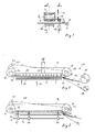
- FIG. 1 shows, in a highly simplified representation, a material web 10 of a packaging material, which in the example shown is continuously moved in accordance with the arrow 12 and, for example, is welded onto and separated from packaging containers in a subsequent station (not shown).
- a conveyor belt 14 with a suitable woven or otherwise perforated structure runs across the width of the material web 10 and is guided and driven by deflection rollers 16 and 18 (FIG. 2).
- the conveyor belt 14 runs in the area of the material web 10 via a suction box 20 which is at least partially open towards the conveyor belt 14 in a manner not shown and otherwise via a pipeline 22 with an Un not shown terdruckario is connected.
- suction conveyors are known per se and are therefore not to be explained in more detail.
- FIG. 2 there is a feed device 24 for labels on the side of the material web 10.
- the self-adhesive labels 26 are located on a carrier tape 28 which is pulled off a supply roll 30.
- the carrier tape 28 is pulled around an acute-angled pull-off edge 32 on the lateral edge of the material web 10 and thereby releases labels onto the conveyor belt 14 in such a way that the non-adhesive sides lie on the conveyor belt and the labels are held in place by the suction box 20.
- the empty carrier tape 28 then runs onto a carrier tape roll 34 which, for example, can contain a controllable drive for the carrier tape, not shown.
- the labels 26 are successively transferred onto the conveyor belt 14 at suitable intervals.
- the conveyor belt 14 is stopped, and the material web 10 is pressed by means of a pressure plate 36 in the direction of arrow 38 against the exposed adhesive side of the labels, so that these immediately open adhere to the material web 10. Possibly. the vacuum in the suction box can be temporarily reduced in the same cycle.
- An essential feature of the invention is concerned with the precise and simple adjustment of the position of the labels in the direction transverse to the material web 10.
- a rail 40 runs across the material web 10, on which a number of sensors, in the illustrated example light barriers 42, 44, 46, are arranged to be longitudinally adjustable.
- the light barriers serve to detect a sensor 48, for example a finger passing through the light barriers, which executes a movement across the material web 10 which is synchronously opposed to one another with respect to the movement of the conveyor belt 14.
- a sensor 48 for example a finger passing through the light barriers, which executes a movement across the material web 10 which is synchronously opposed to one another with respect to the movement of the conveyor belt 14.
- the transmitter 48 is essentially in the position shown in FIG. 2, opposite the feed device 24. With the continuous movement of the lower run of the conveyor belt 14 from right to left in FIG. 3, the transmitter 48 moves increasingly from left to right.
- the transmitter passes the individual light barriers 42, 44, 46, each of which sends a pulse. release the drive of the feed device 24, through which the carrier belt 28 is advanced in such a way that a label 26 is transferred onto the conveyor belt 14.
- the positions of the labels 26 on the filled conveyor belt 14 correspond exactly to the positions of the light barriers 42, 44, 46 in this way.
- the light barriers can be located, for example, in the longitudinal center line of the labels, as shown in FIG. 3.
- an adjusting device (not shown) is preferably provided in the synchronous coupling between the conveyor belt 14 and the transmitter 48.
- the encoder 48 can be connected to a linear drive, not shown. A particularly simple, opposite synchronization results, however, if the encoder 48 is fastened on an endless belt or chain 50 which rotates around gear wheels 52, 54, 56 and is synchronized with the drive of the conveyor belt 14, for example via a reversing gear wheel.
- FIG. 4 and 5 illustrate in simplified form an application example for the labeling device.
- the conveyor belt 14 with the labels 26 runs across a conveyor belt 58 on which there are cans 60, 62, 64.
- the rows of cans 60, 62, 64 fed in the longitudinal direction have different distances.
- the dispensing position of the labels can therefore be adapted to the entry position of the cans below the labeling device without difficulty and on the spot.
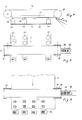
- FIG. 6 shows an application example which essentially corresponds to a top view of FIGS. 2 and 3.
- Labels 26 are applied to a continuously fed material web 10 in the manner described.
- Lids 66 are then formed from the material web 10 and are welded, for example, to plastic shells (not shown).
- a particular advantage of the invention is that the position of the individual labels and their spacing for each row of labels are determined by the transmitter and the sensors directly on the basis of the path covered by the transmitter. Since the conveyor belt and the encoder travel the same way, the positions of the sensors that scan the encoder and the labels on the conveyor belt, which are attached in accordance with the pulses of the sensors, match very precisely. This correspondence is independent of the conveying speed of the products or the packaging material and the running speed of the conveyor belt. In contrast, it is with a program Storage of the delivery time of the labels as time information is essential that the speed of the conveyor belt is exactly maintained.
- the encoder can also be attached to the return run of the conveyor belt 14, which executes an opposite synchronous movement to the run of the conveyor belt receiving the labels.
- the arrangement of encoder and sensor for controlling the label drive is of course interchangeable.
Abstract
Description
Die Erfindung betrifft eine Etikettiervorrichtung zur Überführung von selbstklebenden Etiketten von einem Trägerband auf Produkte bzw. deren Verpackung, mit einem quer über die Förderbahn der Produkte oder der Verpackung verlaufenden Transportband, an dessen einem Ende seitlich der Förderbahn eine Abziehkante zur Umlenkung des Trägerbandes und Übertragung der Etiketten auf das Transportband angeordnet ist.The invention relates to a labeling device for transferring self-adhesive labels from a carrier tape to products or their packaging, with a conveyor belt running transversely over the conveying path of the products or the packaging, at one end of which a pulling edge for deflecting the carrier tape and transferring the sidewall of the conveying path Labels are arranged on the conveyor belt.
Derartige Etikettiervorrichtungen dienen dazu, selbstklebende Etiketten auf eine kontinuierlich zugeführte Reihe von Produkten oder ein kontinuierlich zugeführtes Verpakkungs-Bahnmaterial zu übertragen. Die Etiketten werden auf einem Trägerband seitlich der Förderbahn der Produkte oder der Verpackung zugeführt, dort über eine spitzwinklige Abziehkante von der Trägerbahn abgezogen und auf ein quer über die Förderbahn der Produkte verlaufendes Transportband übertragen, von dem sie abgenommen und auf die Produkte aufgedrückt werden.Labeling devices of this type are used to transfer self-adhesive labels to a continuously supplied row of products or a continuously supplied packaging web material. The labels are fed on a carrier belt to the side of the conveyor belt of the products or the packaging, there they are removed from the carrier belt via an acute-angled pull-off edge and transferred to a conveyor belt running across the conveyor belt from which they are removed and pressed onto the products.
Durch geeignete Steuerung des Antriebs des Etiketten-Trägerbandes kann der Zeitpunkt der Abgabe der Etiketten an der Abziehkante und damit der Überführung auf das Transportband bestimmt werden. Sofern, wie es in vielen Fällen der Fall ist, auf der Förderbahn nebeneinander mehrere Produkte gleichzeitig zugeführt werden und dementsprechend mehrere Etiketten in Abständen nacheinander auf das Transportband übertragen werden müssen, erfolgt die Steuerung der Position und der Abstände der Etiketten auf dem Transportband über ein die Abstände der Produkte und die Geschwindigkeit des Transportbandes berücksichtigendes Programm, durch das die Bewegung des Trägerbandes und damit die Abgabe der Etiketten gesteuert werden kann. Die Aufstellung eines derartigen Programms erfordert eine Reihe von komplizierten Rechenvorgängen und setzt im übrigen eine genaue Einhaltung sämtlicher Bewegungsgeschwindigkeiten voraus. Positions-Korrekturen der Etiketten in bezug auf die Produkte oder deren Verpackung sind daher im laufenden Betrieb allenfalls insoweit möglich, als der Abgabezeitpunkt für alle Etiketten vor- oder zurückgestellt oder der Abstand aller Etiketten gleichmäßig geändert werden kann. Weitergehende Postionsänderungen erfordern die Verwendung eines vollständig neuen Programms.By suitably controlling the drive of the label carrier belt, the point in time at which the labels are released at the pull-off edge and thus the transfer to the conveyor belt can be determined. If, as is the case in many cases, several products are fed simultaneously on the conveyor track and accordingly several labels have to be transferred to the conveyor belt at intervals, the position and the spacing of the labels on the conveyor belt are controlled via a Program taking into account the distances of the products and the speed of the conveyor belt, by means of which the movement of the carrier belt and thus the dispensing of the labels can be controlled. The preparation of such a program requires a number of complicated computing processes and, moreover, presupposes an exact observance of all movement speeds. Position corrections of the labels in relation to the products or their packaging are therefore only possible during operation to the extent that the delivery time for all labels can be postponed or postponed or the spacing of all labels can be changed evenly. Further changes in position require the use of a completely new program.
In der Praxis ist es jedoch vielfach erforderlich oder zumindest wünschenswert, Feinkorrekturen für die Position der Etiketten in jeder der nebeneinander zugeführten Produkt-Reihen vornehmen zu können, etwa, weil die Produkte in unterschiedlichen Abständen oder unterschiedlicher Orientierung zugeführt werden, eine Etikettierung in unterschiedlichen Positionen der Produkte vorgesehen ist oder dergleichen.In practice, however, it is often necessary or at least desirable to be able to make fine corrections for the position of the labels in each of the product rows fed next to one another, for example because the products are fed in at different intervals or with different orientations, labeling in different positions of the Products is provided or the like.
Der Erfindung liegt daher die Aufgabe zugrunde, eine Etikettiervorrichtung des Gattungsbegriffs derart auszubilden, daß eine Einstellung der Etikettier-Position quer zur Förderbahn an Ort und Stelle und in einfacher Weise möglich ist.The invention is therefore based on the object of designing a labeling device of the generic type in such a way that an adjustment of the labeling position transversely to the conveyor track is possible in place and in a simple manner.
Diese Aufgabe wird erfindungsgemäß bei einer Etikettiervorrichtung der eingangs genannten Art gelöst durch einen quer über die Förderbahn gegenläufig-synchron zu dem Transportband beweglichen Geber und wenigstens einen seitlich der Bewegungsbahn des Gebers angeordneten, quer zur Förderbahn verstellbaren Sensor zur Abtastung des Gebers, der ein den Antrieb des Etiketten-Trägerbandes steuerndes Signal beim Passieren des Gebers abgibt.This object is achieved according to the invention in a labeling device of the type mentioned at the outset by an encoder which can be moved transversely across the conveyor path and in synchronism with the conveyor belt, and at least one sensor which is arranged laterally to the movement path of the encoder and which is adjustable transversely to the conveyor path, for scanning the encoder which is the drive of the label carrier tape controlling signal when passing the encoder.
Der Sensor oder vorzugsweise mehrere Sensoren werden auf bestimmte Punkte der gewünschten Etikettier-Position, beispielsweise auf die Längsmittellinie der Etiketten eingestellt. Während der Bewegung des Transportbandes passiert der Geber, von der der Etikettenzufuhr gegenüberliegenden Seite der Förderbahn her, nacheinander die Sensoren, so daß die Sensoren nacheinander ein Signal zum Vorrücken des Antriebs des Etiketten-Trägerbandes liefern und jeweils ein Etikett auf das Transportband übertragen wird. Nachdem das Transportband beispielsweise mit drei aufeinander folgenden Etiketten besetzt worden ist, werden die Etiketten auf die Produkte aufgedrückt. Es ist dabei stets gewährleistet, daß sich die Etiketten jeweils in den Positionen der Sensoren befinden, die auf die gewünschte Etikettierposition eingestellt werden können. Da es keinerlei Schwierigkeiten bereitet, die Bewegung des Gebers gegenläufig mit der Bewegung des Transportbandes zu synchronisieren, entsprechen,.die Positionen der Etiketten auf dem Transportband stets sehr genau den Positionen der Sensoren. Zur Korrektur dieser Positionen können die Sensoren beispielsweise auf einer quer über die Förderbahn verlaufenden Schiene verstellt werden.The sensor or sensors are preferably a plurality of, for example, set k to specific points of the desired Eti ettier position on the longitudinal center line of the labels. During the movement of the conveyor belt, the encoder passes the sensors one after the other from the side of the conveyor track opposite the label feed, so that the sensors successively deliver a signal for advancing the drive of the label carrier belt and a label is transferred to the conveyor belt. After the conveyor belt has been filled with three consecutive labels, for example, the labels are pressed onto the products. It is always ensured that the labels are each in the positions of the sensors that can be set to the desired labeling position. Since there is no difficulty in synchronizing the movement of the encoder in opposite directions with the movement of the conveyor belt, the positions of the labels on the conveyor belt always correspond very precisely to the positions of the sensors. To correct these positions, the sensors can be adjusted, for example, on a rail running across the conveyor track.
Die Sensoren können beispielsweise Lichtschranken, jedoch auch anderweitige Abtastschalter beliebiger und bekannter Art sein.The sensors can be light barriers, for example, but also other scanning switches of any known type.
Der Geber, beispielsweise ein von Lichtschranken erfaßbarer Geberfinger, kann beispielsweise auf einem endlosen Band oder einer endlosen Kette montiert sein, die gegenläufig-synchron zu dem Transportband antreibbar ist.The sensor, for example a sensor finger that can be detected by light barriers, can be mounted, for example, on an endless belt or chain that can be driven in opposite directions and synchronously with the conveyor belt.
Das Transportband kann beispielsweise ein perforiertes Band sein, das über einen Saugkasten läuft. Derartige Förderer sind an sich bekannt. Sie bieten hier den Vorteil, daß die Etiketten nach dem Abziehen von ihrem Trägerband auf der nicht-klebenden Seite festgehalten und angesaugt werden können und sodann mit der außen liegenden, klebenden Seite unmittelbar auf die Produkte aufgedrückt werden können.The conveyor belt can, for example, be a perforated belt that runs over a suction box. Such promoters are known per se. They offer the advantage here that the labels can be held on the non-adhesive side after they have been pulled off their carrier tape and can be sucked in and then can be pressed directly onto the products with the external, adhesive side.
Weitere Einzelheiten der Erfindung ergeben sich aus den Unteransprüchen.Further details of the invention emerge from the subclaims.
Im Folgenden werden bevorzugte Ausführungsbeispiele der Erfindung anhand der beigefügten Zeichnung näher erläutert.Preferred embodiments of the Er invention explained in more detail with reference to the accompanying drawing.
- Fig. 1 ist eine schematische Seiten-Teilansicht einer erfindungsgemäßen Etikettiervorrichtung;Fig. 1 is a schematic partial side view of a labeling device according to the invention;
- Fig. 2 ist eine schematische Schnittdarstellung entsprechend der Linie 2-2 in Fig. 1;Fig. 2 is a schematic sectional view taken along the line 2-2 in Fig. 1;
- Fig. 3 ist eine ähnliche Darstellung entsprechend der Linie 3-3 in Fig. 1;Fig. 3 is a similar representation along line 3-3 in Fig. 1;
- Fig. 4 veranschaulicht eine erste Verwendungsmöglichkeit für die Etikettiervorrichtung;4 illustrates a first possible use for the labeling device;
- Fig. 5 ist eine schematische Draufsicht zu Fig. 4;Fig. 5 is a schematic top view of Fig. 4;
- Fig. 6 zeigt eine zweite Einsatzmöglichkeit in schematischer Draufsicht.Fig. 6 shows a second application in a schematic plan view.
In Fig. 1 ist in stark vereinfachter Darstellung zunächst eine Materialbahn 10 eines Verpackungsmaterials gezeigt, die im dargestellten Beispiel entsprechend dem Pfeil 12 kontinuierlich bewegt und beispielsweise in einer nicht gezeigten, anschließenden Station auf Verpackungsbehälter aufgeschweißt und abgetrennt wird. Quer über die Breite der Materialbahn 10 verläuft ein Transportband 14 mit einer geeigneten gewebten oder in anderer Weise perforierten Struktur, das durch Umlenkrollen 16 und 18 (Fig. 2) geführt und angetrieben wird. Wie aus Fig. 2 hervorgeht, verläuft das Transportband 14 im Bereich der Materialbahn 10 über einen Saugkasten 20, der in nicht gezeigter Weise zum Transportband 14 hin zumindest teilweise offen und im übrigen über eine Rohrleitung 22 mit einer nicht gezeigten Unterdruckquelle verbunden ist. Derartige Saugförderer sind für sich bekannt und sollen daher nicht näher erläutert werden.1 shows, in a highly simplified representation, a
Wie aus Fig. 2 hervorgeht, befindet sich seitlich der Materialbahn 10 eine Zufuhreinrichtung 24 für Etiketten. Die selbstklebenden Etiketten 26 befinden sich auf einem Trägerband 28, das von einer Vorratsrolle 30 abgezogen wird. Das Trägerband 28 wird um eine spitzwinklige Abziehkante 32 am seitlichen Rand der Materialbahn 10 herumgezogen und gibt dabei Etiketten derart an das Transportband 14 ab, daß die nicht-klebenden Seiten auf dem Transportband liegen und die Etiketten durch den Saugkasten 20 festgehalten werden. Das leere Trägerband 28 läuft sodann auf eine Trägerbandrolle 34 auf, die beispielsweise einen nicht gezeigten, steuerbaren Antrieb für das Trägerband enthalten kann.As can be seen from FIG. 2, there is a
Wie später näher erläutert werden soll, werden die Etiketten 26 nacheinander in geeigneten Abständen auf das Transportband 14 überführt. Wenn die Etiketten die gewünschte seitliche Verteilung quer über der Materialbahn 10 erreicht haben, wird das Transportband 14 angehalten, und die Materialbahn 10 wird mit Hilfe einer Andrückplatte 36 in Richtung des Pfeiles 38 gegen die freiliegende klebende Seite der Etiketten gedrückt, so daß diese unmittelbar auf der Materialbahn 10 anhaften. Ggf. kann der Unterdruck in dem Saugkasten im gleichen Takt vorübergehend abgebaut werden.As will be explained in more detail later, the
Ein wesentliches Merkmal der Erfindung befaßt sich mit der genauen und einfachen Einstellung der Position der Etiketten in Richtung quer zu der Materialbahn 10. In diesem Zusammenhang wird insbesondere auf Fig. 3 in Verbindung mit Fig. 1 bezug genommen. In dem in Fig. 3 gezeigten Beispiel verläuft quer über die Materialbahn 10 eine Schiene 40, auf der eine Anzahl von Sensoren, im dargestellten Beispiel Lichtschranken 42,44,46 längsverstellbar angeordnet sind.An essential feature of the invention is concerned with the precise and simple adjustment of the position of the labels in the direction transverse to the
Die Lichtschranken dienen zum Erfassen eines Gebers 48, etwa eines die Lichtschranken passierenden Fingers, der eine Bewegung quer über die Materialbahn 10 ausführt, die genau gegenläufig-synchron in bezug auf die Bewegung des Transportbandes 14 ist. Beim Beginn der Übertragung der Etiketten für eine Reihe von nebeneinanderliegenden Produkten auf das Transportband befindet sich der Geber 48 im wesentlichen in der in Fig. 2 gezeigten, der Zufuhreinrichtung 24 gegenüberliegenden Position. Mit der fortlaufenden Bewegung des unteren Trums des Transportbandes 14 von rechts nach links in Fig. 3 bewegt sich der Geber 48 zunehmend von links nach rechts. Der Geber passiert dabei die einzelnen Lichtschranken 42,44,46, die jeweils einen Impuls an. den Antrieb der Zufuhreinrichtung 24 abgeben, durch den das Trägerband 28 derart vorgerückt wird, daß ein Etikett 26 auf das Transportband 14 überführt wird.The light barriers serve to detect a
Es ist erkennbar, daß die Positionen der Etiketten 26 auf dem aufgefüllten Transportband 14 auf diese Weise genau den Positionen der Lichtschranken 42,44,46 entsprechen. Durch geeignete Zuordnung der Geber-Position in bezug auf den Zeitpunkt der Übertragung der Etiketten auf das Transportband 14 können die Lichtschranken beispielsweise in der Längsmittellinie der Etiketten liegen, wie es in Fig. 3 gezeigt ist. Zur genauen Koordinierung der Lichtschranken mit einer gewünschten Position der Etiketten ist vorzugsweise in der Synchron-Koppelung zwischen dem Transportband 14 und dem Geber 48 eine nicht gezeigte Verstelleinrichtung vorgesehen.It can be seen that the positions of the
Der Geber 48 kann mit einem nicht gezeigten Linear-Antrieb verbunden sein. Eine besonders einfache, gegenläufige Synchronisation ergibt sich jedoch, wenn der Geber 48 auf einem endlosen Band oder einer endlosen Kette 50 befestigt ist, die um Zahnräder 52,54,56 umläuft und mit dem Antrieb des Transportbandes 14, beispielsweise über ein Umkehrzahnrad synchronisiert ist.The
Fig. 4 und 5 veranschaulichen in vereinfachter Form ein Anwendungsbeispiel für die Etikettiervorrichtung. Das Transportband 14 mit den Etiketten 26 verläuft quer über ein Förderband 58, auf dem sich Dosen 60,62,64 befinden. Im dargestellten Beispiel weisen die in Längsrichtung zugeführten Reihen der Dosen 60,62,64 unterschiedliche Abstände auf. Die Abgabeposition der Etiketten kann daher ohne Schwierigkeiten und an Ort und Stelle an die Einlaufposition der Dosen unterhalb der Etikettiervorrichtung angepaßt werden.4 and 5 illustrate in simplified form an application example for the labeling device. The
Fig. 6 zeigt ein Anwendungsbeispiel, das im wesentlichen einer Draufsicht der Figuren 2 und 3 entspricht. Auf eine kontinuierlich zugeführte Materialbahn 10 werden Etiketten 26 in der beschriebenen Weise aufgebracht. Aus der Materialbahn 10 werden anschließend Deckel 66 gebildet, die beispielsweise auf nicht gezeigte Schalen aus Kunststoff aufgeschweißt werden.FIG. 6 shows an application example which essentially corresponds to a top view of FIGS. 2 and 3.
Es liegt auf der Hand, daß insbesondere im Hinblick auf den Geber und dessen gegenläufigen Antrieb sowie in bezug auf die Abtastung des Gebers Abwandlungen gegenüber der beschriebenen Ausführungsform durch Verwendung anderer üblicher Antriebs- und Abtastmechanismen möglich sind.It is obvious that, in particular with regard to the encoder and its counter-rotating drive and with respect to the scanning of the encoder, modifications to the described embodiment are possible by using other conventional drive and scanning mechanisms.
Ein besonderer Vorteil der Erfindung liegt darin, daß durch den Geber und die Sensoren für jede Etiketten-Reihe die Position der einzelnen Etiketten und deren Abstände unmittelbar anhand des Weges ermittelt werden, den der Geber zurücklegt. Da das Transportband und der Geber den gleichen Weg zurücklegen, stimmen die Positionen der Sensoren, die den Geber abtasten, und der Etiketten auf dem Transportband, die entsprechend den Impulsen der Sensoren angebracht werden, sehr genau überein. Diese Übereinstimmung ist unabhängig von der Fördergeschwindigkeit der Produkte oder des Verpackungsmaterials und der Laufgeschwindigkeit des Transportbandes. Demgegenüber ist es bei einer Programmspeicherung des Abgabezeitpunkts der Etiketten als Zeitinformation unerläßlich, daß die Geschwindigkeit des Transportbandes genau eingehalten wird.A particular advantage of the invention is that the position of the individual labels and their spacing for each row of labels are determined by the transmitter and the sensors directly on the basis of the path covered by the transmitter. Since the conveyor belt and the encoder travel the same way, the positions of the sensors that scan the encoder and the labels on the conveyor belt, which are attached in accordance with the pulses of the sensors, match very precisely. This correspondence is independent of the conveying speed of the products or the packaging material and the running speed of the conveyor belt. In contrast, it is with a program Storage of the delivery time of the labels as time information is essential that the speed of the conveyor belt is exactly maintained.
Der Geber kann ggf. auch auf dem Rücklauftrum des Transportbandes 14 angebracht sein, das eine gegenläufig-synchrone Bewegung zu dem die Etiketten aufnehmenden Trum des Transportbandes ausführt. Die Anordnung von Geber und Sensor für die Steuerung des Etiketten-Antriebes ist selbstverständlich austauschbar.If necessary, the encoder can also be attached to the return run of the
Claims (8)
Priority Applications (1)
| Application Number | Priority Date | Filing Date | Title |
|---|---|---|---|
| AT81103929T ATE12475T1 (en) | 1980-05-22 | 1981-05-21 | LABELING DEVICE. |
Applications Claiming Priority (2)
| Application Number | Priority Date | Filing Date | Title |
|---|---|---|---|
| DE3019506 | 1980-05-22 | ||
| DE3019506A DE3019506C2 (en) | 1980-05-22 | 1980-05-22 | Labeling device |
Publications (3)
| Publication Number | Publication Date |
|---|---|
| EP0040831A2 true EP0040831A2 (en) | 1981-12-02 |
| EP0040831A3 EP0040831A3 (en) | 1982-10-27 |
| EP0040831B1 EP0040831B1 (en) | 1985-04-03 |
Family
ID=6103023
Family Applications (1)
| Application Number | Title | Priority Date | Filing Date |
|---|---|---|---|
| EP81103929A Expired EP0040831B1 (en) | 1980-05-22 | 1981-05-21 | Labelling machine |
Country Status (5)
| Country | Link |
|---|---|
| US (1) | US4324608A (en) |
| EP (1) | EP0040831B1 (en) |
| AT (1) | ATE12475T1 (en) |
| CA (1) | CA1140900A (en) |
| DE (2) | DE3019506C2 (en) |
Cited By (4)
| Publication number | Priority date | Publication date | Assignee | Title |
|---|---|---|---|---|
| WO1987001675A1 (en) * | 1985-09-17 | 1987-03-26 | Heino Ilsemann | Labelling device |
| WO2008046526A1 (en) * | 2006-10-05 | 2008-04-24 | Cfs Germany Gmbh | Packaging machine with a labelling device |
| US7661246B2 (en) | 2005-04-15 | 2010-02-16 | Cfs Germany Gmbh | Packaging machine for producing packaging comprising a transponder |
| EP2412654A4 (en) * | 2009-03-27 | 2015-12-23 | Fuji Seal Int Inc | Film supplying apparatus |
Families Citing this family (24)
| Publication number | Priority date | Publication date | Assignee | Title |
|---|---|---|---|---|
| US4842660A (en) * | 1986-03-28 | 1989-06-27 | New Jersey Machine, Inc. | Continuous motion pressure sensitive labeling system and method |
| US5021116A (en) * | 1988-07-18 | 1991-06-04 | Aexcel Corporation | Labeling machine |
| CA2002285C (en) * | 1988-11-07 | 2002-01-08 | Thomas L. Brandt | Container label and system for applying same |
| JP2571151B2 (en) * | 1990-11-22 | 1997-01-16 | 富士写真フイルム株式会社 | Terminal stop tape supply device |
| US5256239A (en) * | 1991-05-03 | 1993-10-26 | New Jersey Machine Inc. | Continously moving web pressure-sensitive labeler |
| US5281296A (en) * | 1991-07-30 | 1994-01-25 | Markem Corporation | Label applicator |
| US5470420A (en) * | 1992-07-31 | 1995-11-28 | Eastman Kodak Company | Apparatus for label application using Bernoulli Effect |
| US5888343A (en) * | 1995-09-05 | 1999-03-30 | Fingerhut Corporation | Labeling apparatus and method |
| US5876555A (en) * | 1996-10-31 | 1999-03-02 | Gunther International, Ltd. | Apparatus and method for applying a label to a package |
| US6143105A (en) * | 1998-04-27 | 2000-11-07 | Moore U.S.A., Inc. | Semi-automatic mailpiece printer/label applicator |
| US6543505B1 (en) * | 2000-04-21 | 2003-04-08 | Koch Equipment, Llc | Empty package detector for labeling apparatus |
| DE10037864A1 (en) * | 2000-08-01 | 2002-03-07 | Kraemer & Grebe Kg | Absetzkasten |
| US6729375B2 (en) * | 2001-06-19 | 2004-05-04 | Joe & Samia Management Inc. | Labelling apparatus and method |
| ATE422468T1 (en) * | 2005-04-04 | 2009-02-15 | Elmoprint Aps Maskinfabrik | DEVICE FOR DISPENSING LABELS |
| US7318877B2 (en) * | 2005-11-23 | 2008-01-15 | Koch Equipment Llc | High speed labeling device and method |
| DE102007033628B3 (en) * | 2007-07-17 | 2008-11-13 | Mr Etikettiertechnik Gmbh & Co. Kg | Method and device for multi-lane application of labels |
| JP2011195197A (en) * | 2010-02-26 | 2011-10-06 | Takara Pac Ltd | High speed label transfer and sticking device |
| DE102010019855A1 (en) * | 2010-05-07 | 2011-11-10 | Itec-Ingenieurbüro für Hygiene Und Lebensmitteltechnik GmbH | Method for labeling stackable reusable transport and storage container utilized for transportation and storage of e.g. meat, involves securing sheet at discrete points of film by heat sealing at wall of container, so that sheet is removable |
| DE102011112328C5 (en) | 2011-09-02 | 2017-09-21 | Multivac Marking & Inspection Gmbh & Co. Kg | Method for operating a labeling device of a thermoforming packaging machine |
| DE102012212180A1 (en) * | 2012-07-12 | 2014-01-16 | Bizerba Gmbh & Co. Kg | applicator |
| CN103662232A (en) * | 2012-08-31 | 2014-03-26 | 鸿富锦精密工业(深圳)有限公司 | Stripping machine |
| DE102016112789A1 (en) | 2016-07-12 | 2018-01-18 | Krones Ag | Method and device for labeling first packaging |
| CN109353628A (en) * | 2018-12-11 | 2019-02-19 | 常熟利星光电科技有限公司 | A kind of double labels synchronization device for labeling of power supply line |
| DE102020205800A1 (en) | 2020-05-08 | 2021-11-11 | Multivac Marking & Inspection Gmbh & Co. Kg | LABELING DEVICE AND METHOD FOR DELIVERING LABELS |
Citations (4)
| Publication number | Priority date | Publication date | Assignee | Title |
|---|---|---|---|---|
| FR2343653A1 (en) * | 1976-03-08 | 1977-10-07 | Label Aire Inc | LABEL APPLICATOR AGENCY IN MATRIX |
| FR2360416A1 (en) * | 1976-08-06 | 1978-03-03 | Ipsden Investments Ltd | Automatic labelling system - comprises labels secured to both sides of flexible supporting strip by pressure sensitive adhesive |
| DE2647556A1 (en) * | 1976-10-21 | 1978-04-27 | Mr Selbstklebe Technik Etikett | Adhesive labels handling equipment - places labels in number of rows and has label carrier with press-on device positioned across labelled objects |
| US4210484A (en) * | 1978-08-03 | 1980-07-01 | Label-Aire Inc. | Label spreader applicator |
Family Cites Families (1)
| Publication number | Priority date | Publication date | Assignee | Title |
|---|---|---|---|---|
| US4024011A (en) * | 1976-06-24 | 1977-05-17 | Compac Corporation | Label applicator with repetitive sequential firing order and method |
-
1980
- 1980-05-22 DE DE3019506A patent/DE3019506C2/en not_active Expired
-
1981
- 1981-05-21 AT AT81103929T patent/ATE12475T1/en active
- 1981-05-21 DE DE8181103929T patent/DE3169648D1/en not_active Expired
- 1981-05-21 EP EP81103929A patent/EP0040831B1/en not_active Expired
- 1981-05-22 CA CA000378102A patent/CA1140900A/en not_active Expired
- 1981-05-22 US US06/266,234 patent/US4324608A/en not_active Expired - Fee Related
Patent Citations (4)
| Publication number | Priority date | Publication date | Assignee | Title |
|---|---|---|---|---|
| FR2343653A1 (en) * | 1976-03-08 | 1977-10-07 | Label Aire Inc | LABEL APPLICATOR AGENCY IN MATRIX |
| FR2360416A1 (en) * | 1976-08-06 | 1978-03-03 | Ipsden Investments Ltd | Automatic labelling system - comprises labels secured to both sides of flexible supporting strip by pressure sensitive adhesive |
| DE2647556A1 (en) * | 1976-10-21 | 1978-04-27 | Mr Selbstklebe Technik Etikett | Adhesive labels handling equipment - places labels in number of rows and has label carrier with press-on device positioned across labelled objects |
| US4210484A (en) * | 1978-08-03 | 1980-07-01 | Label-Aire Inc. | Label spreader applicator |
Cited By (5)
| Publication number | Priority date | Publication date | Assignee | Title |
|---|---|---|---|---|
| WO1987001675A1 (en) * | 1985-09-17 | 1987-03-26 | Heino Ilsemann | Labelling device |
| EP0218925A1 (en) * | 1985-09-17 | 1987-04-22 | Heino Ilsemann | Labelling machine |
| US7661246B2 (en) | 2005-04-15 | 2010-02-16 | Cfs Germany Gmbh | Packaging machine for producing packaging comprising a transponder |
| WO2008046526A1 (en) * | 2006-10-05 | 2008-04-24 | Cfs Germany Gmbh | Packaging machine with a labelling device |
| EP2412654A4 (en) * | 2009-03-27 | 2015-12-23 | Fuji Seal Int Inc | Film supplying apparatus |
Also Published As
| Publication number | Publication date |
|---|---|
| DE3019506C2 (en) | 1983-12-22 |
| ATE12475T1 (en) | 1985-04-15 |
| EP0040831A3 (en) | 1982-10-27 |
| DE3019506A1 (en) | 1981-11-26 |
| US4324608A (en) | 1982-04-13 |
| CA1140900A (en) | 1983-02-08 |
| DE3169648D1 (en) | 1985-05-09 |
| EP0040831B1 (en) | 1985-04-03 |
Similar Documents
| Publication | Publication Date | Title |
|---|---|---|
| EP0040831B1 (en) | Labelling machine | |
| EP1751005B1 (en) | Method and device for packaging flat articles | |
| CH643788A5 (en) | DEVICE FOR LABELING OBJECTS. | |
| DE3241636C2 (en) | ||
| WO1983004013A2 (en) | Device for cutting sets of continuous forms or the like | |
| DE102008007890B4 (en) | Cross web labeling process and labeller | |
| EP2167389B1 (en) | Method and device for applying labels in multiple tracks | |
| EP0842856A1 (en) | Method and device for making banderoles and applying them to (cigarette) packages | |
| DE10228243B4 (en) | Cross-track labeling method and apparatus | |
| DE2802446A1 (en) | DEVICE FOR ALIGNING A NUMBER OF MOVING OBJECTS WITH EACH OTHER | |
| EP0360108A1 (en) | Process and apparatus for delivering labels | |
| DE3800664A1 (en) | METHOD AND DEVICE FOR PRODUCING A FOLDING BOXES HAVING A COLLAR, IN PARTICULAR FOR CIGARETTES | |
| EP0833791A1 (en) | Feed device for a packaging machine | |
| DE4013116A1 (en) | Stacking process for flat cardboard blanks - produces gap in overlapping flow for undisturbed removal of stack | |
| EP0574750A1 (en) | Method and device for transforming a multiple row container stream in a single row of containers | |
| DE2217032C3 (en) | Device for applying blanks made from a continuous web to objects | |
| EP1332970B1 (en) | Method and device for cutting tubular labels from a flat tubular label web | |
| EP0584337B1 (en) | Labelling system | |
| EP1216817A2 (en) | Machine for producing packaging bags | |
| EP0014858B1 (en) | Method and device for attaching tear strips or the like to a web of wrapping material | |
| DE1202118B (en) | Device for intermittent conveying of webs or web parts made of paper, cardboard or the like coming out of a punch. | |
| EP0384221B1 (en) | Device for applying reinforcement patches provided with glue to a web provided with transverse perforations | |
| EP0806390B1 (en) | Device for replacing a first web by a second web | |
| DE69919477T2 (en) | Method and machine for packaging a group of articles | |
| DE2227135C3 (en) | Device for group-wise separation of a predetermined number of flat objects which overlap in a scale-like manner |
Legal Events
| Date | Code | Title | Description |
|---|---|---|---|
| PUAI | Public reference made under article 153(3) epc to a published international application that has entered the european phase |
Free format text: ORIGINAL CODE: 0009012 |
|
| AK | Designated contracting states |
Designated state(s): AT BE CH DE FR GB IT LU NL SE |
|
| PUAL | Search report despatched |
Free format text: ORIGINAL CODE: 0009013 |
|
| AK | Designated contracting states |
Designated state(s): AT BE CH DE FR GB IT LU NL SE |
|
| 17P | Request for examination filed |
Effective date: 19830426 |
|
| GRAA | (expected) grant |
Free format text: ORIGINAL CODE: 0009210 |
|
| AK | Designated contracting states |
Designated state(s): AT BE CH DE FR GB IT LI LU NL SE |
|
| PG25 | Lapsed in a contracting state [announced via postgrant information from national office to epo] |
Ref country code: NL Effective date: 19850403 Ref country code: IT Free format text: LAPSE BECAUSE OF FAILURE TO SUBMIT A TRANSLATION OF THE DESCRIPTION OR TO PAY THE FEE WITHIN THE PRESCRIBED TIME-LIMIT;WARNING: LAPSES OF ITALIAN PATENTS WITH EFFECTIVE DATE BEFORE 2007 MAY HAVE OCCURRED AT ANY TIME BEFORE 2007. THE CORRECT EFFECTIVE DATE MAY BE DIFFERENT FROM THE ONE RECORDED. Effective date: 19850403 |
|
| REF | Corresponds to: |
Ref document number: 12475 Country of ref document: AT Date of ref document: 19850415 Kind code of ref document: T |
|
| REF | Corresponds to: |
Ref document number: 3169648 Country of ref document: DE Date of ref document: 19850509 |
|
| PG25 | Lapsed in a contracting state [announced via postgrant information from national office to epo] |
Ref country code: AT Effective date: 19850521 |
|
| PG25 | Lapsed in a contracting state [announced via postgrant information from national office to epo] |
Ref country code: SE Effective date: 19850522 |
|
| PG25 | Lapsed in a contracting state [announced via postgrant information from national office to epo] |
Ref country code: LU Free format text: LAPSE BECAUSE OF NON-PAYMENT OF DUE FEES Effective date: 19850531 |
|
| ET | Fr: translation filed | ||
| NLV1 | Nl: lapsed or annulled due to failure to fulfill the requirements of art. 29p and 29m of the patents act | ||
| PLBE | No opposition filed within time limit |
Free format text: ORIGINAL CODE: 0009261 |
|
| STAA | Information on the status of an ep patent application or granted ep patent |
Free format text: STATUS: NO OPPOSITION FILED WITHIN TIME LIMIT |
|
| 26N | No opposition filed | ||
| PGFP | Annual fee paid to national office [announced via postgrant information from national office to epo] |
Ref country code: GB Payment date: 19900430 Year of fee payment: 10 |
|
| PGFP | Annual fee paid to national office [announced via postgrant information from national office to epo] |
Ref country code: BE Payment date: 19900516 Year of fee payment: 10 |
|
| PGFP | Annual fee paid to national office [announced via postgrant information from national office to epo] |
Ref country code: CH Payment date: 19900530 Year of fee payment: 10 |
|
| PG25 | Lapsed in a contracting state [announced via postgrant information from national office to epo] |
Ref country code: GB Effective date: 19910521 |
|
| PG25 | Lapsed in a contracting state [announced via postgrant information from national office to epo] |
Ref country code: LI Effective date: 19910531 Ref country code: CH Effective date: 19910531 Ref country code: BE Effective date: 19910531 |
|
| BERE | Be: lapsed |
Owner name: KLINGER MAX H. Effective date: 19910531 |
|
| GBPC | Gb: european patent ceased through non-payment of renewal fee | ||
| REG | Reference to a national code |
Ref country code: CH Ref legal event code: PL |
|
| EUG | Se: european patent has lapsed |
Ref document number: 81103929.6 Effective date: 19860728 |
|
| PGFP | Annual fee paid to national office [announced via postgrant information from national office to epo] |
Ref country code: FR Payment date: 19950516 Year of fee payment: 15 |
|
| PGFP | Annual fee paid to national office [announced via postgrant information from national office to epo] |
Ref country code: DE Payment date: 19950531 Year of fee payment: 15 |
|
| PG25 | Lapsed in a contracting state [announced via postgrant information from national office to epo] |
Ref country code: FR Effective date: 19970131 |
|
| PG25 | Lapsed in a contracting state [announced via postgrant information from national office to epo] |
Ref country code: DE Effective date: 19970201 |
|
| REG | Reference to a national code |
Ref country code: FR Ref legal event code: ST |