EP0046404A1 - Apparatus for the dynamic in-circuit testing of electronic digital circuit elements - Google Patents
Apparatus for the dynamic in-circuit testing of electronic digital circuit elements Download PDFInfo
- Publication number
- EP0046404A1 EP0046404A1 EP81303755A EP81303755A EP0046404A1 EP 0046404 A1 EP0046404 A1 EP 0046404A1 EP 81303755 A EP81303755 A EP 81303755A EP 81303755 A EP81303755 A EP 81303755A EP 0046404 A1 EP0046404 A1 EP 0046404A1
- Authority
- EP
- European Patent Office
- Prior art keywords
- test
- signals
- terminal
- signal
- terminals
- Prior art date
- Legal status (The legal status is an assumption and is not a legal conclusion. Google has not performed a legal analysis and makes no representation as to the accuracy of the status listed.)
- Granted
Links
Images


Classifications
-
- G—PHYSICS
- G01—MEASURING; TESTING
- G01R—MEASURING ELECTRIC VARIABLES; MEASURING MAGNETIC VARIABLES
- G01R31/00—Arrangements for testing electric properties; Arrangements for locating electric faults; Arrangements for electrical testing characterised by what is being tested not provided for elsewhere
- G01R31/28—Testing of electronic circuits, e.g. by signal tracer
- G01R31/317—Testing of digital circuits
- G01R31/3181—Functional testing
- G01R31/319—Tester hardware, i.e. output processing circuits
- G01R31/31903—Tester hardware, i.e. output processing circuits tester configuration
- G01R31/31915—In-circuit Testers
Landscapes
- Engineering & Computer Science (AREA)
- General Engineering & Computer Science (AREA)
- Physics & Mathematics (AREA)
- General Physics & Mathematics (AREA)
- Tests Of Electronic Circuits (AREA)
- Test And Diagnosis Of Digital Computers (AREA)
- Semiconductor Integrated Circuits (AREA)
- Logic Circuits (AREA)
Abstract
Description
- This invention is concerned with apparatus for the dynamic in-circuit testing of electronic digital circuit elements.
- The continuing development of electronic digital circuit elements, and electronic circuits including such elements, of greater diversity and complexity is accompanied by corresponding increases in the difficulty and expense of testing them quickly and adequately, either during assembly of the circuit or subsequently after the circuit has been in use for some time. Such testing is important commercially, since the sale of equipment with too high an incidence of faults will result in loss of reputation for quality, while if the testing is unduly difficult and time-consuming, requiring expensive skilled manpower for its implementation, then the resultant increase in the servicing cost may be unacceptable.
- Traditional forms of test gear such as oscilloscopes and logic analyzers require a high degree of skill in the test operator. In the application of another technique known as signature analysis a known bit stream is passed through the digital circuit and the resultant "signature" produced by that bit-stream examined for response at different points in the circuit. In a further technique a microprocessor or the like under test is replaced with an emulating microprocessor which controls the circuit in its place; such a system can only indicate that a malfunction exists in the devices on the bus but not the location of the malfunction. Simple replacement of an entire faulty circuit board is also employed, but is expensive in inventory, and subsequently the faulty board must be examined for repair.
- It is of course known to test a circuit element by direct comparison with a pre-tested sample of the same element, since this reduces the amount of information required to determine whether or not the tested element is satisfactory. However, such testing has been difficult and time-consuming with known arrangements. A typical circuit board will carry a wide variety of different elements to be tested, all of which usually are operative with different parameters that must be pre-set before the particular element can be tested. If a number of similar boards are to be tested, the same element on all the boards can be examined one after the other while the test equipment is set for that element, but this then involves moving from board to board between each test.
- It is therefore an object of the invention to provide a new apparatus for the dynamic in-circuit testing of electronic digital circuit elements.
- It is a more specific object to provide such apparatus with which an element is tested rapidly by direct comparison with the same element provided by the testing apparatus.
- Test apparatus which is a particular preferred embodiment of the invention will now be described, by way of example, with reference to the accompanying Schematic drawings, wherein:
- FIGURE 1 is a generalised block diagram of the preferred embodiment,
- FIGURE 2 is a more detailed schematic diagram of the external interface block of the perferred embodiment,
- FIGURE 3 is a more detailed schematic diagram of the internal interface block,
- FIGURE 4 is a more detailed schematic diagram of the library block,
- FIGURE 5 is a more detailed schematic diagram of the comparison and fault detection block,
- FIGURE 6 is a timing diagram to illustrate the timing system used in the comparison and fault detection block, and
- FIGURE 7 is a logic diagram to show the operation of the control block in controlling the operation of the other blocks of the preferred embodiment.
- FIGURE 8 is a detailed logic circuit for implementing the logic diagram of Figure 7,
- FIGURE 9 is a detail from the external interface block of Figure 2 and also illustrates an alternative embodiment for obtaining offset of the input logic signals,
- FIGURE 10 is a detail from the internal interface block of Figure 3 to show a specific structure for control blocks therein, and
- FIGURE 11 is a detail from the library block of Figure 4 to show the generation of a toggle signal from a toggle logic block thereof.
- The test apparatus illustrated is intended for the testing of elements made under current industry manufacturing standards wherein each element has the form of a rectangular block of either 7.5 mm or 15 mm width, provided along its two longer parallel sides with two respective rows of uniformly- spaced metal terminal pins. Currently such elements have from 14 to 40 pins, each of which depending upon the internal architecture may be a signal input terminal, a signal output terminal, or be bi-directional. For testing purposes with this embodiment an element is temporarily connected to the test apparatus by use of a known type of spring-jawed clip, the opposed jaws of which carry respective sets of electric contacts each arranged to engage a respective pin when the clip is clamped on the element. A multi-wire cable carries signals from the jaw contacts and thus to and from the respective pins.
- In addition to the clip the apparatus provides five other leads as follows:
- 1) A ground lead for connection to the ground of the board on which the device is mounted,
- . 2). A lead (EX CLK) to connect to the external clock or its equivalent on the test board,
- 3) A lead (INT CLK) to provide an internal clock from the apparatus to the test board if such is a clock needed, or if the test clock is too fast for the apparatus,
- 4) A lead (INT CLK) providing the complement of 3), and
- 5)An external lead for giving a reset signal to restart a programmable device or board operation when required.
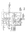
- Turning now to Figure 1, the jaw contacts of such a
clip 10 are connected via acable 12 to corresponding contacts of an external interface (E.I.)block 14, which is in turn connected to an internal interface (I.I.)block 16. Signals from the I.I. block may pass directly to a comparison and fault detector (C.F.D.)block 18, or may go to alibrary block 20, as will be described below. Signals also pass from thelibrary block 20 to the C.F.D.block 18 and signals indicating the "status" of each of the pins of an element under test are passed from the C.F.D.block 18 to adisplay block 22, which in this embodiment gives a visual display. It will be understood that for example in an embodiment employed in an automatic test facility such a visual display may not be necessary and may be omitted or replaced by some other unit as required by the purchaser for indicating that the tested element has passed or failed the test and/or taking some action depending upon pass or failure of the test. - Certain control functions to be described below, particularly those required during a test, are performed by a
control block 24, which has direct access to the I.I.block 16 and C.F.D.block 18, while other functions required in preparation for and following a test are performed by amicrocomputer 26, which has direct access to all of the blocks with the exception of thedisplay block 22.Microcomputer 26 also has access to auser interface block 28 including a keyboard and alphanumeric display by which a human operator can insert necessary information into the apparatus and also receive information, prompts and commands therefrom. As withdisplay block 22, the configuration of theuser interface block 28 will also depend upon whether a human operator is required, or whether the test apparatus is being run by a machine. The function of each of the above-described blocks and their inter-relation with one another will be described below. - The operation of apparatus of the invention depends upon the presence in the
library block 20 of a device or element that is a duplicate of the device to be tested, or that can be made to operate as if it were a duplicate of the tested device. Such duplication of the tested device may be for example by adjustment of the voltage levels and/or timing of the input/ output signals involved. This may be contrasted with test apparatus of the kind employing a microcomputer in which the microcomputer software or firmware is written so that the microcomputer will simulate the device under test, requiring complete and detailed information as to the operation of the device as well as the signals involved in its operation. - The library block consists of at least one board, usually a plurality of boards, each of which has connected to the busbars thereof a plurality of devices that are to be tested, all wired'to the busbars to permit individual access to each element and also to the pins of each element as required. Each such board can consist, for example, of a group of dissimilar elements all from the same manufacturer, or a group of similar elements, one from each of the available manufacturers, or a group of devices all of the same technology e.g. TTL; MOS; CMOS; DTL; ECL, etc. Again, each library board can be as identical as possible in content and layout to a circuit board that is to be tested, and this is particularly valuable in ensuring that heating conditions, time delays, intercouplings, leakages, etc. will be as nearly as possible the same.
- Each library board also includes a read only memory means connected to appropriate busbars of the board and containing necessary information for each element on the board, such as its index number for operator identification, the identification of the board on which it is mounted, the library board bus coordinates that must be enabled and accessed to power the element and access its terminals, the status of each of the terminals of the element (i.e. whether it is an input, output or bidirectional terminal), the voltage bias levels required for operation, the speed of operation and the corresponding time delays that may be required for its signals to be compared with those of the test device, and the time required for a complete test of its operation. For economy in manufacture this memory preferably is a single central unit for the whole board, but of a type that can be re-programmed when required if any of the devices on the board is replaced by a different device.
- Let it first be assumed that a human operator is to test a single element on a board having a clock signal that is directly usable by the test apparatus and of a kind that does not require a reset signal for its operation. Before commencing the test the operator will interrogate the test apparatus via the
user interface 28 to determine whether or not the same or an equivalent device is in the library block. Each device to be tested and the reference device are identified to the operator by the above-mentioned identification number stored in the respective library board memory. The operator supplies this number to themicrocomputer 26 via anumerical keypad 30 in theuser interface 28 and then presses the search (SRCH)key 32, causing the microcomputer to search the library memories and display on analpanumeric display unit 34 in theuser interface 28 whether or not the device is in the library, and if so the library board on which it is located. If the search does not find a device with this identification the computer will provide thedisplay unit 34 with an appropriate display such as "not available". - Once assured that the device can be tested the operator now connects EX CLK lead 35 to the board on which the device is mounted to receive the clock signal, connects
ground lead 36 to the board ground, putsclip 10 on to the device and presses enter key 37 to enter the device identification data as shown on thedisplay 34. The microcomputer now interrogates the respective library memory unit for the pertinent information on the selected device and also powers the selected device, so that it is in the same condition of operation as the external test device. At the same time the data about the selected device is employed by the microcomputer to set the E.I.block 14 to provide the required bias voltages; to set the I.I.block 16 so that it will properly route the signals it receives, as will be described below, and to set thecontrol block 24 so that the latter will initiate and control a testing cycle for the selected device. This data about the selected device will be stored in suitable registers which may be provided in the microcomputer block or in the respective block to which the data has been transferred. If the register is in the respective block then once the data has been transferred to it the microcomputer can disable itself from further access to that register until there is a need to replace the data for a new test device. Having performed these functions the microcomputer enters on thedisplay 34 an indication that a test is possible and then, except for various accessory functions described below, disables itself from taking any further part in the test per se. - The test element is in active condition in its circuit, which must be powered up for the test to be possible, so that the element is receiving the input signals and power supply or supplies that are available to it from its own board; the element will also be delivering output signals to the respective output terminals which, if the element is functioning properly, are appropriate for the input signals and power that it is receiving. As described above the signal at a particular terminal pin of the test element will be supplied via
clip 10 to the external interface, where its level will be changed if necessary as previously set by the microcomputer. If it is an input signal it is routed automatically by the I.I.block 16 to the C.F.D. block and also to the corresponding terminal pin of the library reference device and becomes an input to that device. If it is an output signal it is routed automatically by the I.I.block 16 to the C.F.D.block 18 and is prevented from access to the library reference element. If the signal is changing from input to output then in input mode it will be routed as above for an input signal while in output mode it will be routed as above for an output signal under control of a "toggle" signal supplied to the I.I.block 16. - Upon the operator pressing the
test key 38 thecontrol block 24 will now operate the I.I.block 16, thelibrary block 20, and the C.F.D.block 18 to scan synchronously and simultaneously the pins of the external device and the same pins of the library device. The input signal on any input pin of the test device will be routed by the I.I.block 16 to the library reference device, while the output signal on any output pin of the test device will be routed directly to the C.F.D.block 18 to be compared with the signal from the same pin of the library reference device. It is usually preferred for a complete test to scan over a relatively large number of cycles since, in general, each such cycle takes only a small fraction of a second and the total time for an exhaustive test is very small as compared with the tine required to move theclip 10 from one element to another. In the case when one or more of the pins are bi-directional a plurality of scans will be required until the device has been tested in all possible states, the I.I.block 16 routing the signal as required in dependence upon whether it is an input or an output. - The C.F.D.
block 18 comprises a bank of combinatorial logic elements, forty in this particular embodiment since forty pin devices are to be tested, each of which compares the signal from the respective pin of the test device with that from the corresponding pin of the library reference device and feeds any output to a respective one of fortyindicator devices 40 in thedisplay block 22. Thus, if any one of the combination logic elements is fed two different digital signals the respective indicator will be actuated to show a fault condition on that pin, whereupon the operator will know not only that the device is faulty, but the pin or pins at which the fault or faults is occurring. An audible signal may also be employed to alert the operator that a fault is present. The clip can then be moved to another similar device and thetest button 38 again pressed to obtain a test of the new device, and so on. At any time the status of the pins and whether or not a fault is present can be read by the microcomputer and this information supplied to theinterface 28 or some other external apparatus. - It was assumed above that the device under test employed the clock signal from its own board, but frequently this is not the case, and a clock signal or complementary clock signal can be supplied from the microcomputer via the E.I.
block 14 throughrespective leads lead 44. The direction of the clock signal to be supplied from the test apparatus is selectable, depending upon whether triggering occurs on the rising or falling edge of the clock pulse. The information as to what clock signal is required will be in the library memory, but needs to be fed to the microprocessor as an instruction. The operator therefore presses aclock key 46, whereupon the microprocessor will display the clock requirement for the device and a menu for operation of thenumeric pad 30 to obtain the necessary signal; for example the menu will instruct the operator to press "1" for the microprocessor internal clock to supply the device with a clock signal of one polarity; press "2" for an internal clock signal with opposite polarity; and press "3" if an external clock signal is already provided. - It may be found that the external clock signal is too fast to be usable or for convenience in testing, in which case the internal clock will be selected by the operator. Upon insertion by the operator of the length of test required the microcomputer will calculate the number of test cycles required for this test duration and will terminate the test cycle upon expiry of this time. The microcomputer includes a frequency counter unit which is actuated by operation of a frequency key (FREQ) 48, whereupon the
display 34 will display the actual frequency and polarity of the clock that is in use. - Upon the operator pressing a
time key 50 the microcomputer will show in thedisplay 34 the duration of the test to be made and a menu to change the time if this is not satisfactory.- The required test duration is selected by keying the number of milliseconds via thenumerical pad 30 and then pressing theenter key 36. This feature is used, for example, if the fault is known to be intermittent, or if a longer test time than usual is required, e.g. for a soaking test. - The circuits and logic arrangement of the various blocks will now be described in greater detail, other features of the apparatus also being described where this is appropriate.
- This constitutes a buffer of high input impedance between the test apparatus and the device being tested, so as not to unduly affect the operation of the test device, and also acts as a level translator to enable the test apparatus to deal with families of devices other than those used in the apparatus blocks. Thus, this particular preferred embodiment employs signal levels and logic thresholds characteristic of TTL logic devices and in the absence of the
interface block 14 it could only conveniently test devices employing such levels and thresholds, since other types requiring different logic thresholds might not give signals that could be handled or even detected by the test apparatus. Part of the information stored in the library memory on each library board and supplied by the microcomputer to the external interface block is the bias level offset required to translate the digital signals received and transmitted by the E.I. block to the standard levels for TTL logic devices of a maximum of 0.8 volts for "0" and a minimum of 2.4 volts for "1". The operator presses a'bias key 52 to be told the offset that has been given to the E.I. block by the microcomputer for the test device together with a menu for change if this should prove to be necessary. If necessary the number of millivolts of change required is set by thekey pad 30 and entered by pressing theenter key 36. - Referring now to Figure 2, which shows in greater detail the circuit of the external interface block, the forty leads in the
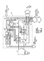
cable 12 and thesingle clock lead 35 feed their signals to respective highinput impedance amplifiers 54, while the corresponding forty one separate output leads 56 feed their signals to respective offsetmodules 58, each of which will accept the digital signal received onlead 56 and feed the corresponding TTL logic signal out on itsoutput lead 60 to the I.I.block 16. An internal power unit (not shown) provides each offset module on input leads 62 and 64 respectively with the voltages appropriate to produce a TTL logic "1" or "0" on theoutput lead 60. The offset data from the microcomputer is also fed via alead 66 to ashift register 68, which controls the output of a digital/ analog converter anddriver 70 to produce a ground reference voltage for the signals from the offset modules. This analog ground signal is fed to aground detector 72 which is also connected to theexternal ground lead 36. Upon detection of current flow between the two grounds the detector transmits a signal vialead 76 to the microcomputer that a ground reference is available and the test may proceed, and otherwise not. - Referring now to Figure 3, which shows in greater detail the circuit of the I.I. or routing
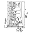
block 16, each output lead 60 from E.I. block 14-constitutes an input lead to a respective set of three controlled switch devices 80 (designated C1, C2 and C3 respectively) which set is controlled by arespective control block 82. The input to eachcontrol block 82 is from two separate 40-bit registers 84 and 86, called respectively the Y and Z register, which are supplied with the required information as to the status of the respective device pin from the library memory via themicrocomputer 26. The bit signals received by each control block 82 from the Z and Y registers is used in combination with a toggle signal received from the library block vialead 88 to issue the necessary control signals to the switches C1, C2 and C3. The two bit YZ input specifies whether the signal is an input or an output or a toggle, and the incoming toggle signal will in the latter case make the final determination between input and output as required. Thus, if the incoming signal is an input then the two switches C2 and C3 are closed while the switch Cl is open and the signal is fed vialeads block 18 and vialead 94 to thelibrary block 20. If the incoming signal is an output then the two switches C2 and C3 are open and the switch C1 is closed, whereupon the signal from the E.I.block 14 cannot access the library device, but can access the C.F.D.block 18 vialead 92, while the corresponding output signal from the library device can return to the I.I. block vialead 94 and access the C.F.D. block via thelead 90. - A special situation arises when the device to be tested is of a kind, such as a shift register, which must be synchronised with the library device. In such case each
control device 82 is issued a "synchronous mode" signal vialead 96; in this mode with an input signal the switches C1 and C3 are now open while switch C2 is closed so that the signal can only input the C.F.D.block 18 vialeads 90 and 92 and is blocked from the library device vialead 94, while with an output signal the switch C1 is closed and both switches C2 and C3 are open so that access to the library device from the E.I. block 'is again prevented while the library device can feed to the C.F.D.block 18 vialeads control block 24 then issues a restart signal to the cycle control to indicate this failure and put the apparatus in standby mode; at the same time the microcomputer block will provide an instruction "failure to synchronise" on thedisplay 34, since the most likely reason is of course a faulty device. - Figure 4 is a more detailed circuit drawing of a part of one library board in the library block although, as will be understood, a typical embodiment of the invention will usually comprise a number of different boards. As described above each board 98 includes a read only
memory 100 connected byleads lead 106 to acontrol logic device 108 that will in turn close aswitch 110 permitting power to be supplied to the board. At the same time the computer block issues a "select device" signal onlead 112 to aregister 114 that in turn will cause closing of arespective switch 116 that will permit the powering up of the selected library device. 118 corresponding to the test device. Each library device is connected via aboard bus 119 to alibrary block bus 120 and by theleads 94 to the I.I.block 16. If the selected device is of a type in which one or more of the pins is bidirectional then the board also carries a respectivetoggle logic block 121 arranged for that device and which is selected by closing of therespective switch 116, this block feeding the toggle signal as described above on leads 88 to the I.I.block 16. - Since the test apparatus itself employs TTL logic levels such devices in the library are immediately compatible with the test apparatus circuits and can be connected directly to the
board bus 119 and thence to thelibrary bus 120. Devices such asdevice 122, corresponding to test devices that require offset voltages to be provided by the E.I.block 14, cannot be directly connected in this manner because of this inherent incompatability; instead they are connected to a sub-bus 123 that is connected to theboard bus 119 viadriver 124 providing to the sub-bus 123 the voltages required for proper operation of the device, this driver being enabled by the board select signal. - Turning now to Figures 5 and 6 the C.F.D. block receives signals from the
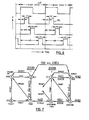
library block 20 vialeads 90, and from the I.I.block 16 vialeads 92; these signals are fed to respective high speed memory elements (latches) 126 and 128, also labelled L1 and L21 and thence to a respectivecombinatorial logic element 130. The output from eachelement 130 is fed to a respective high speed memory element (latch) 132, also labelled L3. - If the digital signals received by an
element 130 do not correspond it detects the lack of correspondence as a fault and activates adriver 134 that lights therespective lamp 40 in thedisplay block 22. The outputs of all of theelements 130 are fed to acombination detector device 136 that feeds a "fault detected" signal onlead 138 to the microcomputer, so that it will give an indication of a fault detection. The device feeds a corresponding signal onlead 139 to the C.F.D. block, so as to "stop" the test immediately with the fault or faults indicated, since otherwise the test might move on to a situation where there is no fault and the fault indication would be lost. At the same time all the outputs are fed to amultiplex detector register 140 that can be interrogated by the micro computer via leads 142 to determine which of the device pins have been detected as faulty and provide a read-out either on thedisplay 34 or some equivalent unit, e.g. a printer. - Owing to the high speed at which the apparatus operates it is necessary to control the operation of the
latches - A
high speed clock 144 feeds aripple counter 146 which produces the necessary large number of uniform pulses. Inform- ation as to the time delays tdl, td2 and td3 required for the particular device are supplied by the microcomputer block to aregister 148 after this information has been extracted by it from the R.O.M. 100 in the respective library board. Thecounter 146 and register 148 feed acomparator 150 which in turn feeds the selected pulses to acontrol.logic module 152 that is also fed with the appropriate clock signal to synchronise its operation with the test device. Referring to Figure 6 a pulse is fed after time delay td1 from the start of the respective clock cycle to open latches L1 and the signals from the I.I.block 16 are sampled during the period P1. Latches L2 are opened for another period P2 that occurs after time delay td2 to sample the signals from thelibrary block 20, while latches L3 are opened for a last period P3,that occurs after time delay td3 to sample the outputs of thecombinatorial logic devices 130. All three pulses occur within one clock cycle and there is no overlap between them, so that the actual speed of operation of the tested device and the propagation times through the apparatus are immaterial as long as this condition can be fulfilled. In a particular preferred embodiment operating at 5 Mhz the length of one clock cycle will be 200 nanoseconds and each pulse will typically have a duration of 20 nanoseconds. - Reference is now made to Figures 7 and 8 which are respectively a logic diagram to show the manner in which the control block is employed to control the other blocks of the apparatus and to issue control signals to those other blocks as required, and a specific circuit for that purpose. The circuit is of pulsed asynchronous logic configuration employing TTL Schottky NAND logic gates of the 74S-family e.g. 74S00; 74510; 74S20 and 74S30. Other families and other logic systems can of course be employed, as will be fully apparent to those skilled in the art.
- Upon powering-up of the apparatus it is required to be in standby node represented by
state 1. If the apparatus is not already in this state then the required prompt is not provided by the microcomputer and accordingly it is driven to the state by the operator pressing areset key 166, whereupon the microcomputer will issue the necessary instruction signal to the logic. If the operator now presses thetest key 38 the microcomputer will issue its test signal that will cause the logic to move asynchronously tostate 2, also called system restart I. In this second state the input/outputs to the library block are enabled and those to the C.F.D. block are disabled; also an external reset signal is applied to the test device if it is of the type that requires such a signal. - For devices not requiring an external reset signal, such as simple logic gates, the logic can move directly to
Test state 7 in which all inputs/outputs are enabled together with the C.F.D.block 18, provided the following conditions are met: - a) a test has previously been initiated (TEST)
- b) the external system clock is at logic zero (
SYSCLK ), and - c) the device has been determined previously by examination of the library block memory to be of the type not requiring an external reset (
SYN) . - Assuming that the logic is now in
state 7, if now a fault is detected, the logic moves tostate 8 in which all the inputs/ outputs are disabled to stop or "freeze" the apparatus in the fault condition, while all accumulated information from the cycle with regard to the fault is held, so that it can be examined and displayed by the slower-operating-microcomputer. A return tostandby state 1 is only obtained by issue of the reset signal, for example by the operator. If no fault is detected then upon expiry of the test period the logic issues a reset signal to return directly fromstate 7 tostate 1. - If synchronisation is required at
state 2 then the necessary information comes from the library block as described above and with the presence of only conditions a) and b) above the logic is now moved tostate 4, where the necessary check is made for synchronisation. As described above the lack of "synchronisation" is detected as a "fault", but the logic is not armed to drive the apparatus into "fault state" as in the asynchronousloop containing state 8. Upon detection of this "fault" the logic drives immediately asynchronously tostate 3, which is also calledsystem restart 2. In thisstate 3, as was described above, all inputs into the library block are disabled, but all outputs are enabled and compared, so that the library device is "inactive". As soon as synchronisation is obtained there is no "fault" detected and with the system clock at logic zero the logic returns tostate 4; this loop can of course repeat and also states 5 and 6 are employed to confirm that synchronism has been achieved, to take account for example of "glitches" on the clock lines giving false clock indications.States station 3 and the cycle repeated. If there is no "fault" indication atstate 6 and the system clock is at the required higher level then the logic passes immediately tostate 7 and the test takes place. To avoid "lock-out" of the logic in any of the states provision is made for the application of a reset signal at each station that will-drive the logic tostandby state 1 for the sequence to be repeated. - Figure 8 illustrates one form of logic circuit to implement the logic diagram of Figure 7. As indicated above, in practice there are many different ways in which the circuit can be arranged depending upon the logic chosen by the designer. This circuit uses 21
multi-input NAND modules 184 through to 224, 12inverters 226 through to 248 and 4 NORmodules 250 through to 256 connected as shown. Since all of the elements are interactive a step-by-step explanation of its function would be prolix and is unnecessary for those skilled in the art. The circuit consists essentially of three set/reset registers identified by the initials K, L and M. Register K consists ofmodules modules modules -

- Thus it will be seen that to move from
state 1 tostate 2 the registers K and L remain unchanged (0) while register M is set (1). Again to move fromstate 3 tostate 4 registers K and L remain respectively in their unchanged (0) form and set (1) states while register M must be reset from (1) to (0). - The setting and resetting of the registers also requires the following relations to be present, among the various signals, the period between symbols indicating "or":-
-

- As will be apparent to those skilled in the art from the description of the apparatus the performance required for the microcomputer block is well within the capability of many currently available units. The particular preferred embodiment described employs an Intel 8085 based central processor unit together with four No. 2733 EPROMS each of four kilobytes capacity; four No. 2114 static RAMS each of half kilobytes capacity; and three No. 8155 static RAMS each of 1.5 kilobytes capacity and 16 I/O ports to provide a total of 48 I/O ports.
- It will be seen that all of the different blocks of the apparatus can be constructed using hardware only, since their individual functions are fixed, and the only software and/or. firmware needed is in the microcomputer, which can be a readily available unit. Moreover the speed of operation of the various blocks, and therefore of the complete apparatus,is independent of the speed of operation of the microcomputer, which typically is much slower than is possible with a hardware-only block. For example, as described above a preferred minimum speed of operation of the hardware of the preferred embodiment during a test is at 50 Megaherz; the operating speed of a suitable microcomputer is about 4 Megaherz, but each instruction of the microcomputer requires at least several machine cycles for its execution, so that its actual operating speed is only a fraction of the speed of which the test apparatus is capable. This slower speed of the computer block is immaterial since the testing by the hardware portion of the apparatus is independent of the computer. The resultant apparatus can therefore readily be provided as a "turn- key" unit not requiring any software programming by the user.
- A particularly advantageous characteristic of the apparatus of the invention is that it is not necessary to know the internal construction or mode of operation of the test device for it to be tested successfully, as long as information is available as to the status of its pins during operation.
- The apparatus can therefore be used to test a proprietory or military device for which the manufacturer is unwilling or unable to provide information as to its operation, and used to test a batch of devices whose operation is unknown as long as one can be sure that a correctly functioning device can be selected to serve as the library device.
- Because of the possibilities described above of testing external devices making use of an internal library device that is equivalent but of a different family, the library device having one identification may also be identified as .corresponding to a number of different configurations, usually referred to as packages. This information is stored in the respective library R.O.M. 100 and will be displayed by the microcomputer block on the
display 34 upon interrogation of the memory, which will show that the device in the library is of "package" type. A package (PKG)key 154 is then pressed, whereupon the microcomputer will present a menu for selection via the numeric pad of the different packages that are available. Such selection actuates the microcomputer block to provide the offsets and time delays required to make the internal device equivalent to the external device, and to set the test period that will result in a satisfactory test. - The use of microcomputer control of the hardware segments of the test apparatus also permits the storage of a test sequence, as is required for example for the examination of a circuit board carrying a number of different devices. This can be accomplished using a "scratchpad" random access memory (RAM) of the computer block, in which case the test sequence that is entered will be lost when the apparatus is powered down. Alternatively, if the apparatus is employed frequently or principally to test a particular board then that test sequence can be stored in the computer block by a programmable read only memory unit (PROM).
- If the operator wishes to test with a PROM stored test sequence it is only necessary to press a sequence (SEQ)
key 156 when a sequence identification will be produced by! the microcomputer ondisplay 34, or a menu will appear if more than one sequence is stored. In this sequence mode the operator places theclip 10 on the first test device and presses test key 38 whereupon,the device will be tested. Once the device passes or fails the test the clip is passed to the next device and the next and test keys are pressed again. It will be seen therefore that such a sequence can be conducted by a relatively unskilled operator using only an assembly diagram from which the necessary information has been pre-inserted into the PROM. - A temporary test sequence or program is inserted by operation of program (PROG)
key 158, when thedisplay 34 will advise that the apparatus is ready to accept the program and gives it a label. The identification for the first device is entered via the numeric'pad and, if present in the library, this is entered in the sequence in the microcomputer RAM. The operator then presses a "next"key 160 and enters the identification for the second device, this procedure being continued to the end of the sequence when anEnd key 162, used to indicate the end of any data insertion, is pressed. This sequence is now recalled by pressing sequence key 156 and proceeding as with a PROM recorded sequence. - The apparatus includes the usual clear entry key 164 that is used to clear the immediately preceding entry if it has been incorrectly entered. A
reset key 166 is also provided in case at any time the operator wishes to terminate the mode in which the apparatus is operating. A self test (STST)key 168 is also provided for the usual self-testing procedures that are available via the microcomputer. - Referring now to Figure 9 a preferred form of
amplifier 54 for the external interface block consists of a field effect transister (FET) 160 which receives the input from a respective pin of theclip 10, inverts it and feeds it to anNPN transister 162, the output of which feeds online 56 to the offsetmodules 58 or, in an alternative embodiment illustrated by this figure, directly on theoutput line 60 to the I.I.block 16. The signallevel changing modules 58 can for example consist of output devices that are switched on and off by the input signals thereto and produce corresponding output signals of the required TTL logic levels. Such an arrangement permits individual control of the signal levels from each pin but may not be necessary, when the simpler system of Figure 8 can be adopted. Thus, the offset data from themicroprocessor 26 takes the form of an eight bit string, and upon selection of the respective device to be tested, this is fed to ashift register 164, the output of which feeds a digital/analog converter 166, the output of which is fed to anamplifier 168. The amplifier output is fed to the ground of the board on which the device being tested is mounted and shifts the ground voltage of that board to a value such that the signals fed to all of theamplifiers 54 are within the required logic levels to be handled thereby. - Referring now to Figure 10, which illustrates a specific circuit for the control blocks 82 of Figure 3, each of the
switches 80 therein consists for example of an individually controllable tristate buffer such as the 74126 device sold by Texas Instruments. The Y and Z registers feed respective dual input NORgates 170 and 172, the toggle signal fromcontrol block 24 being fed togate 170 with the Y bit, while the output ofgate 170 is fed to gate 172 with the Z bit. Aninverter 174 is connected between the control terminals of switches Cl and C2. The setting for an input signal is a positive bit from the Z register so that the output of NOR gate 172 is low and C1 is disabled; the low signal is inverted byinverter 174 and C2 and C3 are enabled; the presence of a bit from Y is immaterial. The setting for a pure output signal is Z=0 and Y=l when NOR 172 has an output enabling C1 and disabling C2 and C3. With both Z=0 and Y=0 then the state of the switches Cl to C3 depends entirely upon the toggle signal supplied togate 170. System restart II for synchronisation is obtained by applying the signal viadiode 176 to disable switch C3 and thereby prevent the input signals from accessing the library block. - Referring now to Figure 11, any device to be tested of the type which any of the pins can be alternatively input or output requires a respective
toggle logic block 121 to generate the toggle signal that is to be supplied to theinternal interface block 16. The arrangement of one such block will now be described. By way of example only it is assumed that the device to be tested is logically simple, in which outputs are obtained on its output pins, such aspin 10, only when signals S1 and S2 on itscontrol pins output pin 10 is "tristate" i.e. of very high impedance, so that any signals applied thereto from other devices on the bus will be ignored. The "logic block" 121 for such an example reduces to a single NORgate 178 having its inputs connected to the pins S1 and S2 and its output fed to a controllabletristate buffer 180 which is powered when the respective device is powered and permits the toggle signal to be fed to the internal interface block. - The logic block therefore produces a toggle signal logic "1" when the two input signal S1 and S2 are zero, and at all other times will produce toggle signal logic zero to be fed to thegates 170 of Figure 10. - The high speed memory latches of the C.F.D.
block 18 are for example the D-Flip-Flops Type 74273 of Texas Instruments which upon receipt of a signal will hold that signal by remaining in the state to which it was changed by it. The comparator gates are exclusive OR modules type 7486 of Texas Instruments, while the forty element detectors are assembled using for each eight 5-input NOR modules each feeding the input of an 8 input NAND module.
Claims (33)
Priority Applications (1)
| Application Number | Priority Date | Filing Date | Title |
|---|---|---|---|
| AT81303755T ATE14939T1 (en) | 1980-08-18 | 1981-08-18 | APPARATUS FOR DYNAMIC IN-CIRCUIT KEYING OF ELECTRONIC DIGITAL CIRCUIT ELEMENTS. |
Applications Claiming Priority (2)
| Application Number | Priority Date | Filing Date | Title |
|---|---|---|---|
| CA000358461A CA1163721A (en) | 1980-08-18 | 1980-08-18 | Apparatus for the dynamic in-circuit testing of electronic digital circuit elements |
| CA358461 | 1980-08-18 |
Publications (2)
| Publication Number | Publication Date |
|---|---|
| EP0046404A1 true EP0046404A1 (en) | 1982-02-24 |
| EP0046404B1 EP0046404B1 (en) | 1985-08-14 |
Family
ID=4117670
Family Applications (1)
| Application Number | Title | Priority Date | Filing Date |
|---|---|---|---|
| EP81303755A Expired EP0046404B1 (en) | 1980-08-18 | 1981-08-18 | Apparatus for the dynamic in-circuit testing of electronic digital circuit elements |
Country Status (6)
| Country | Link |
|---|---|
| US (1) | US4484329A (en) |
| EP (1) | EP0046404B1 (en) |
| JP (1) | JPS5760269A (en) |
| AT (1) | ATE14939T1 (en) |
| CA (1) | CA1163721A (en) |
| DE (1) | DE3171811D1 (en) |
Cited By (1)
| Publication number | Priority date | Publication date | Assignee | Title |
|---|---|---|---|---|
| DE4430387A1 (en) * | 1993-08-30 | 1995-03-02 | Mitsubishi Electric Corp | Fault-detection system |
Families Citing this family (51)
| Publication number | Priority date | Publication date | Assignee | Title |
|---|---|---|---|---|
| DE3272860D1 (en) * | 1982-05-24 | 1986-10-02 | Ibm Deutschland | Logic analyzer |
| FR2532771B1 (en) * | 1982-09-08 | 1988-05-13 | Service Sa | METHOD AND DEVICE FOR STATICALLY TESTING ALL CONNECTIONS AND PERIPHERAL INTEGRATED CIRCUITS OF A MICROPROCESSOR |
| US5070448A (en) * | 1982-12-09 | 1991-12-03 | International Business Machines Coproration | Method for testing a microprogrammed input/output interface using steal techniques |
| US4628480A (en) * | 1983-10-07 | 1986-12-09 | United Technologies Automotive, Inc. | Arrangement for optimized utilization of I/O pins |
| US4642784A (en) * | 1984-04-26 | 1987-02-10 | Texas Instruments Incorporated | Integrated circuit manufacture |
| JPS60253885A (en) * | 1984-05-30 | 1985-12-14 | Advantest Corp | Circuit tester |
| US4696004A (en) * | 1984-05-28 | 1987-09-22 | Takeda Riken Kogyo Kabushikikaisha | Logic analyzer |
| US4641250A (en) * | 1984-06-11 | 1987-02-03 | The United States Of America As Represented By The Secretary Of The Air Force | Inspection workstation data entry method |
| US4773028A (en) * | 1984-10-01 | 1988-09-20 | Tektronix, Inc. | Method and apparatus for improved monitoring and detection of improper device operation |
| US4691316A (en) * | 1985-02-14 | 1987-09-01 | Support Technologies, Inc. | ROM emulator for diagnostic tester |
| US4744084A (en) * | 1986-02-27 | 1988-05-10 | Mentor Graphics Corporation | Hardware modeling system and method for simulating portions of electrical circuits |
| US4916641A (en) * | 1987-01-16 | 1990-04-10 | Acl Technologies, Inc. | Servovalve analyzer system |
| US4760329A (en) * | 1987-04-23 | 1988-07-26 | Grumman Aerospace Corporation | Programmable tester with bubble memory |
| US4862067A (en) * | 1987-06-24 | 1989-08-29 | Schlumberger Technologies, Inc. | Method and apparatus for in-circuit testing of electronic devices |
| US5426767A (en) * | 1987-08-03 | 1995-06-20 | Compaq Computer Corporation | Method for distinguishing between a 286-type central processing unit and a 386-type central processing unit |
| US6304987B1 (en) | 1995-06-07 | 2001-10-16 | Texas Instruments Incorporated | Integrated test circuit |
| SE461939B (en) * | 1988-09-12 | 1990-04-09 | Kjell Moum | INSTRUMENTS FOR CONTROL OF IC CIRCUITS |
| US5220280A (en) * | 1989-05-11 | 1993-06-15 | Vlsi Technology, Inc. | Method and an apparatus for testing the assembly of a plurality of electrical components on a substrate |
| JP3005250B2 (en) | 1989-06-30 | 2000-01-31 | テキサス インスツルメンツ インコーポレイテツド | Bus monitor integrated circuit |
| US5103169A (en) * | 1989-11-15 | 1992-04-07 | Texas Instruments Incorporated | Relayless interconnections in high performance signal paths |
| US5049814A (en) * | 1989-12-27 | 1991-09-17 | Lsi Logic Corporation | Testing of integrated circuits using clock bursts |
| US5166604A (en) * | 1990-11-13 | 1992-11-24 | Altera Corporation | Methods and apparatus for facilitating scan testing of asynchronous logic circuitry |
| US5255208A (en) * | 1991-08-08 | 1993-10-19 | Aeg Westinghouse Transportation Systems, Inc. | On-line processor based diagnostic system |
| US5323108A (en) * | 1992-01-23 | 1994-06-21 | Hewlett-Packard Company | Method for generating functional tests for printed circuit boards based on pattern matching of models |
| JP3181736B2 (en) * | 1992-12-25 | 2001-07-03 | 三菱電機株式会社 | IC function test apparatus and test method |
| US5333112A (en) * | 1993-03-25 | 1994-07-26 | Aai/Acl Technologies, Inc. | Automatic flow grind system and method |
| US5590136A (en) * | 1995-01-25 | 1996-12-31 | Hewlett-Packard Co | Method for creating an in-circuit test for an electronic device |
| US5539753A (en) * | 1995-08-10 | 1996-07-23 | International Business Machines Corporation | Method and apparatus for output deselecting of data during test |
| US6157210A (en) | 1997-10-16 | 2000-12-05 | Altera Corporation | Programmable logic device with circuitry for observing programmable logic circuit signals and for preloading programmable logic circuits |
| US6408413B1 (en) | 1998-02-18 | 2002-06-18 | Texas Instruments Incorporated | Hierarchical access of test access ports in embedded core integrated circuits |
| US6405335B1 (en) | 1998-02-25 | 2002-06-11 | Texas Instruments Incorporated | Position independent testing of circuits |
| US7058862B2 (en) | 2000-05-26 | 2006-06-06 | Texas Instruments Incorporated | Selecting different 1149.1 TAP domains from update-IR state |
| US6728915B2 (en) | 2000-01-10 | 2004-04-27 | Texas Instruments Incorporated | IC with shared scan cells selectively connected in scan path |
| US6769080B2 (en) | 2000-03-09 | 2004-07-27 | Texas Instruments Incorporated | Scan circuit low power adapter with counter |
| TW580578B (en) * | 2000-10-03 | 2004-03-21 | Concord Idea Corp | System and method for testing integrated circuit devices |
| EP1370883A1 (en) * | 2001-03-13 | 2003-12-17 | Koninklijke Philips Electronics N.V. | Integrated circuit testing device with improved reliability |
| TW555982B (en) * | 2002-01-03 | 2003-10-01 | Winbond Electronics Corp | EDC box compatible with various tester and EDC system |
| US7539912B2 (en) | 2005-12-15 | 2009-05-26 | King Tiger Technology, Inc. | Method and apparatus for testing a fully buffered memory module |
| JP4843451B2 (en) * | 2006-10-19 | 2011-12-21 | 富士通株式会社 | Data generation method, connection check system, and data generation program |
| US7620861B2 (en) * | 2007-05-31 | 2009-11-17 | Kingtiger Technology (Canada) Inc. | Method and apparatus for testing integrated circuits by employing test vector patterns that satisfy passband requirements imposed by communication channels |
| US7757144B2 (en) * | 2007-11-01 | 2010-07-13 | Kingtiger Technology (Canada) Inc. | System and method for testing integrated circuit modules comprising a plurality of integrated circuit devices |
| US7848899B2 (en) * | 2008-06-09 | 2010-12-07 | Kingtiger Technology (Canada) Inc. | Systems and methods for testing integrated circuit devices |
| US8356215B2 (en) * | 2010-01-19 | 2013-01-15 | Kingtiger Technology (Canada) Inc. | Testing apparatus and method for analyzing a memory module operating within an application system |
| US8918686B2 (en) | 2010-08-18 | 2014-12-23 | Kingtiger Technology (Canada) Inc. | Determining data valid windows in a system and method for testing an integrated circuit device |
| US9003256B2 (en) | 2011-09-06 | 2015-04-07 | Kingtiger Technology (Canada) Inc. | System and method for testing integrated circuits by determining the solid timing window |
| WO2013051204A1 (en) * | 2011-10-03 | 2013-04-11 | パナソニック株式会社 | Device for assisting in operation verification and method for assisting in operation verification |
| US8724408B2 (en) | 2011-11-29 | 2014-05-13 | Kingtiger Technology (Canada) Inc. | Systems and methods for testing and assembling memory modules |
| US9117552B2 (en) | 2012-08-28 | 2015-08-25 | Kingtiger Technology(Canada), Inc. | Systems and methods for testing memory |
| US8732630B1 (en) * | 2013-03-15 | 2014-05-20 | Cadence Design Systems, Inc. | Methods, systems, and articles of manufacture for implementing analog behavioral modeling and IP integration using systemverilog hardware description language |
| US8949753B1 (en) | 2013-03-15 | 2015-02-03 | Cadence Design Systems, Inc. | Methods, systems, and articles of manufacture for implementing analog behavioral modeling and IP integration using systemverilog hardware description language |
| US9501592B1 (en) | 2013-03-15 | 2016-11-22 | Cadence Design Systems, Inc. | Methods, systems, and articles of manufacture for implementing analog behavioral modeling and IP integration using systemverilog hardware description language |
Citations (3)
| Publication number | Priority date | Publication date | Assignee | Title |
|---|---|---|---|---|
| US3614608A (en) * | 1969-05-19 | 1971-10-19 | Ibm | Random number statistical logic test system |
| US4125763A (en) * | 1977-07-15 | 1978-11-14 | Fluke Trendar Corporation | Automatic tester for microprocessor board |
| US4168527A (en) * | 1978-02-17 | 1979-09-18 | Winkler Dean A | Analog and digital circuit tester |
Family Cites Families (12)
| Publication number | Priority date | Publication date | Assignee | Title |
|---|---|---|---|---|
| US3684960A (en) * | 1969-05-15 | 1972-08-15 | Ibm | Probe and guide assembly for testing printed circuit cards |
| US4055801A (en) * | 1970-08-18 | 1977-10-25 | Pike Harold L | Automatic electronic test equipment and method |
| US4001818A (en) * | 1975-10-22 | 1977-01-04 | Storage Technology Corporation | Digital circuit failure detector |
| US4039813A (en) * | 1976-04-07 | 1977-08-02 | Sperry Rand Corporation | Apparatus and method for diagnosing digital data devices |
| US4099119A (en) * | 1977-02-03 | 1978-07-04 | Honeywell Inc. | Probe apparatus for in place testing of electrical circuit boards |
| US4270178A (en) * | 1977-07-19 | 1981-05-26 | Beckman Instruments, Inc. | Measuring system incorporating self-testing probe circuit and method for checking signal levels at test points within the system |
| US4122995A (en) * | 1977-08-02 | 1978-10-31 | Burroughs Corporation | Asynchronous digital circuit testing system |
| US4230986A (en) * | 1978-12-18 | 1980-10-28 | Ncr Corporation | Apparatus for facilitating the servicing of printed circuit boards |
| JPS5585264A (en) * | 1978-12-23 | 1980-06-27 | Toshiba Corp | Function test evaluation device for integrated circuit |
| JPS5585265A (en) * | 1978-12-23 | 1980-06-27 | Toshiba Corp | Function test evaluation device for integrated circuit |
| US4271515A (en) * | 1979-03-23 | 1981-06-02 | John Fluke Mfg. Co., Inc. | Universal analog and digital tester |
| US4290015A (en) * | 1979-10-18 | 1981-09-15 | Fairchild Camera & Instrument Corp. | Electrical validator for a printed circuit board test fixture and a method of validation thereof |
-
1980
- 1980-08-18 CA CA000358461A patent/CA1163721A/en not_active Expired
-
1981
- 1981-08-10 US US06/291,727 patent/US4484329A/en not_active Expired - Fee Related
- 1981-08-18 EP EP81303755A patent/EP0046404B1/en not_active Expired
- 1981-08-18 DE DE8181303755T patent/DE3171811D1/en not_active Expired
- 1981-08-18 AT AT81303755T patent/ATE14939T1/en not_active IP Right Cessation
- 1981-08-18 JP JP56128272A patent/JPS5760269A/en active Pending
Patent Citations (3)
| Publication number | Priority date | Publication date | Assignee | Title |
|---|---|---|---|---|
| US3614608A (en) * | 1969-05-19 | 1971-10-19 | Ibm | Random number statistical logic test system |
| US4125763A (en) * | 1977-07-15 | 1978-11-14 | Fluke Trendar Corporation | Automatic tester for microprocessor board |
| US4168527A (en) * | 1978-02-17 | 1979-09-18 | Winkler Dean A | Analog and digital circuit tester |
Cited By (2)
| Publication number | Priority date | Publication date | Assignee | Title |
|---|---|---|---|---|
| DE4430387A1 (en) * | 1993-08-30 | 1995-03-02 | Mitsubishi Electric Corp | Fault-detection system |
| US5617429A (en) * | 1993-08-30 | 1997-04-01 | Mitsubishi Denki Kabushiki Kaisha | Failure detection system for detecting failure of functional blocks of integrated circuits |
Also Published As
| Publication number | Publication date |
|---|---|
| EP0046404B1 (en) | 1985-08-14 |
| CA1163721A (en) | 1984-03-13 |
| US4484329A (en) | 1984-11-20 |
| JPS5760269A (en) | 1982-04-12 |
| ATE14939T1 (en) | 1985-08-15 |
| DE3171811D1 (en) | 1985-09-19 |
Similar Documents
| Publication | Publication Date | Title |
|---|---|---|
| EP0046404B1 (en) | Apparatus for the dynamic in-circuit testing of electronic digital circuit elements | |
| US4860290A (en) | Logic circuit having individually testable logic modules | |
| US4125763A (en) | Automatic tester for microprocessor board | |
| KR890004450B1 (en) | Test vector indexing method & apparatus | |
| US4688222A (en) | Built-in parallel testing circuit for use in a processor | |
| EP0148759A2 (en) | Programmable digital signal testing system | |
| US6347387B1 (en) | Test circuits for testing inter-device FPGA links including a shift register configured from FPGA elements to form a shift block through said inter-device FPGA links | |
| US5809040A (en) | Testable circuit configuration having a plurality of identical circuit blocks | |
| KR970030813A (en) | Programmable Circuits for Testing and Operating the Programmable Gate Array | |
| KR920005233B1 (en) | Testing and maintenance apparatus for data processing systems | |
| JPH06249919A (en) | Interterminal-connection test method of semiconductor integrated circuit device | |
| EP0573816A2 (en) | Data output impedance control | |
| US20050216808A1 (en) | Method and circuit arrangement for testing electrical modules | |
| EP0310152A2 (en) | Test overlay circuit | |
| CA1197322A (en) | Apparatus for the dynamic in-circuit testing of electronic digital circuit elements | |
| EP0157028A1 (en) | Programmable tester | |
| US5339320A (en) | Architecture of circuitry for generating test mode signals | |
| JPS61155874A (en) | Method and device for detecting fault of large-scale integrated circuit | |
| CN112585486A (en) | Extended JTAG controller and method for resetting function by using extended JTAG controller | |
| US7146549B2 (en) | Scan-path flip-flop circuit for integrated circuit memory | |
| CN115469208A (en) | Chip scanning test circuit and chip | |
| CA1197323A (en) | Apparatus for the dynamic in-circuit testing of electronic digital circuit elements | |
| KR970011582B1 (en) | Large-scale integrated circuit device | |
| SU957278A1 (en) | On-line storage unit checking device | |
| JP2630933B2 (en) | IC internal logic test equipment |
Legal Events
| Date | Code | Title | Description |
|---|---|---|---|
| PUAI | Public reference made under article 153(3) epc to a published international application that has entered the european phase |
Free format text: ORIGINAL CODE: 0009012 |
|
| AK | Designated contracting states |
Designated state(s): AT BE CH DE FR GB IT LU NL SE |
|
| 17P | Request for examination filed |
Effective date: 19820806 |
|
| GRAA | (expected) grant |
Free format text: ORIGINAL CODE: 0009210 |
|
| AK | Designated contracting states |
Designated state(s): AT BE CH DE FR GB IT LI LU NL SE |
|
| PG25 | Lapsed in a contracting state [announced via postgrant information from national office to epo] |
Ref country code: NL Effective date: 19850814 Ref country code: LI Effective date: 19850814 Ref country code: IT Free format text: LAPSE BECAUSE OF FAILURE TO SUBMIT A TRANSLATION OF THE DESCRIPTION OR TO PAY THE FEE WITHIN THE PRESCRIBED TIME-LIMIT;WARNING: LAPSES OF ITALIAN PATENTS WITH EFFECTIVE DATE BEFORE 2007 MAY HAVE OCCURRED AT ANY TIME BEFORE 2007. THE CORRECT EFFECTIVE DATE MAY BE DIFFERENT FROM THE ONE RECORDED. Effective date: 19850814 Ref country code: CH Effective date: 19850814 Ref country code: BE Effective date: 19850814 Ref country code: AT Effective date: 19850814 |
|
| REF | Corresponds to: |
Ref document number: 14939 Country of ref document: AT Date of ref document: 19850815 Kind code of ref document: T |
|
| PG25 | Lapsed in a contracting state [announced via postgrant information from national office to epo] |
Ref country code: SE Effective date: 19850830 |
|
| PG25 | Lapsed in a contracting state [announced via postgrant information from national office to epo] |
Ref country code: LU Free format text: LAPSE BECAUSE OF NON-PAYMENT OF DUE FEES Effective date: 19850831 |
|
| REF | Corresponds to: |
Ref document number: 3171811 Country of ref document: DE Date of ref document: 19850919 |
|
| ET | Fr: translation filed | ||
| REG | Reference to a national code |
Ref country code: CH Ref legal event code: PL |
|
| NLV1 | Nl: lapsed or annulled due to failure to fulfill the requirements of art. 29p and 29m of the patents act | ||
| PLBE | No opposition filed within time limit |
Free format text: ORIGINAL CODE: 0009261 |
|
| STAA | Information on the status of an ep patent application or granted ep patent |
Free format text: STATUS: NO OPPOSITION FILED WITHIN TIME LIMIT |
|
| 26N | No opposition filed | ||
| GBPC | Gb: european patent ceased through non-payment of renewal fee | ||
| PG25 | Lapsed in a contracting state [announced via postgrant information from national office to epo] |
Ref country code: FR Free format text: LAPSE BECAUSE OF NON-PAYMENT OF DUE FEES Effective date: 19870430 |
|
| PG25 | Lapsed in a contracting state [announced via postgrant information from national office to epo] |
Ref country code: DE Effective date: 19870501 |
|
| REG | Reference to a national code |
Ref country code: FR Ref legal event code: ST |
|
| PG25 | Lapsed in a contracting state [announced via postgrant information from national office to epo] |
Ref country code: GB Effective date: 19881118 |