EP0048364A2 - Piezoelectric light deflecting apparatus - Google Patents
Piezoelectric light deflecting apparatus Download PDFInfo
- Publication number
- EP0048364A2 EP0048364A2 EP81106908A EP81106908A EP0048364A2 EP 0048364 A2 EP0048364 A2 EP 0048364A2 EP 81106908 A EP81106908 A EP 81106908A EP 81106908 A EP81106908 A EP 81106908A EP 0048364 A2 EP0048364 A2 EP 0048364A2
- Authority
- EP
- European Patent Office
- Prior art keywords
- strips
- mirror
- flexible
- piezoceramic
- voltage
- Prior art date
- Legal status (The legal status is an assumption and is not a legal conclusion. Google has not performed a legal analysis and makes no representation as to the accuracy of the status listed.)
- Granted
Links
Images
Classifications
-
- G—PHYSICS
- G02—OPTICS
- G02B—OPTICAL ELEMENTS, SYSTEMS OR APPARATUS
- G02B7/00—Mountings, adjusting means, or light-tight connections, for optical elements
- G02B7/18—Mountings, adjusting means, or light-tight connections, for optical elements for prisms; for mirrors
- G02B7/182—Mountings, adjusting means, or light-tight connections, for optical elements for prisms; for mirrors for mirrors
- G02B7/1821—Mountings, adjusting means, or light-tight connections, for optical elements for prisms; for mirrors for mirrors for rotating or oscillating mirrors
Definitions
- the invention relates to a piezoelectric light deflecting apparatus having a mirror which can be caused to execute a rotary oscillation by a piezoelectric device energized by an AC voltage.
- Piezoelectric light deflecting apparatuses are known (US-PS 35 44 202, US-PS 35 44 201, US-PS 35 08 814, DE-AS 19 22 423 and DE-AS 23 21 211).
- the known deflection systems are arranged to operate at resonance. Their practical use is however generally limited because they are very sensitive to vibration and shocks.
- the principal object underlying the present invention is thus to provide a piezoelectric light deflecting apparatus of the initially named kind by means of which a mirror of a predetermined size can be operated so that it follows the electrical voltage and executes a rotary oscillation within a specified range.
- the mechanical construction should additionally be substantially insensitive to vibrations and shocks.
- two piezoceramic flexible strips each clamped at one end are arranged in a plane with their ends remote from the ends at which they are clamped lying opposite and spaced apart from each other; that the flexible strips are energized by an AC voltage which differs significantly from the resonant frequency of the flexible strips and is preferably less than this resonant frequency so that they oscillate in counterphase and that the mirror is arranged parallel to the two flexible strips in the region of their free ends and is connected to the free ends of the flexible strips in each case via a respective resilient member.
- first and second piezoceramic strips each having a clamped end and a free end, said strips being substantially aligned in one plane with their free ends facing and spaced apart from each other, by AC voltage means having a frequency which differs significantly from a resonant frequency of said strips for energizing said strips to execute oscillations so that said free ends are periodically displaced in counterphase out of said plane and by respective resilient mounting means extending between said free ends and said mirror for mounting said mirror on strips.
- each resilient member consists of a short, flexible synthetic leg which is fastened to the free end of the associated flexible strip at right angles to the plane of the flexible strip and parallel to the free end faces thereof.
- Each synthetic leg is preferably connected to the free end face of the associated flexible strip.
- the suppression of natural osciallations is achieved, in accordance with the invention, by connecting both flexible strips to a circuit arrangement which consists of an amplifier part, a charge amplifier and an all-pass filter.
- a feedback electrode should be provided on at least one of the flexible strips.
- the deflection of the piezoceramic strip produces a change in the state of charge on the feedback electrode.
- This is amplified via a charge amplifier.
- the voltage at the output of the charge amplifier is a representation of the rotary oscillatory movement of the mirror and indeed displaced by a transit time T
- the function of the subsequent all-pass filter is to delay the feedback signal.
- the delayed feedback signal is added to the input voltage of the function generator which generates a l AC voltage.
- the total delay time should be half the duration of one period of the mechanical natural oscillation. This ensures that a natural oscillation generated for example by a step function is automatically quenched after the time T/2.
- the preferred embodiment of the invention operates using first and second piezoceramic strips it is also possible to use only a single piezoceramic strip and to replace the other piezoceramic strip with an effectively rigid mounting.
- piezoelectric light deflecting apparatus having a mirror which can be caused to execute a rotary oscillation by a piezoelectric device energized by an AC voltage
- the apparatus being characterized by an elongate piezoceramic strip having a clamped end and a free end, by resilient means connecting said free end to said mirror, by means spaced from said free end for mounting said mirror by for pivotal movement relative to fixed structure and AC voltage means having a frequency which differs significantly from the resonant frequency of the piezoceramic strip for energizing said piezoceramic strip to produce oscillating movement of said free end and thereby rotary oscillation of said mirror.
- first and second, piezoceramic flexible strips 11 and 12 are respectively clamped in two spaced apart blocks 20/that they lie in a plane with their free end faces facing one another and spaced apart by a small distance x.
- the blocks 20 are fastened to a frame or housing and can be regarded as fixed structure.
- the first and second flexible strips 11, 12 thus lie opposite one another in a common plane.
- the two flexible strips are of substantially rectangular shape with the oppositely disposed end faces 15 extending parallel to one another and spaced apart by the distance x.
- the earth connections 21 for the flexible strips 11, 12 project beyond the surfaces of the blocks 20 which face away from the free end faces 15.
- Short,flexible,synthetic legs 14 are fastened at right angles to the flexible strips 11 and 12 at the oppositely disposed end faces 15.
- the flexible synthetic legs 14 carry a mirror 13 which is arranged at a distance above the slot between the two flexible strips 11, 12.
- the upper ends of the synthetic limbs or webs 14 are fixedly connected with the lower side of the mirror 13 which is arranged symmetrically on the legs 14.
- the two flexible strips 11, 12 are excited to execute a counterphase oscillatory movement so that their free ends are periodically displaced in counterphase out of the common plane by means of an AC voltage U which is fed to electrodes 22 arranged on the upper and lower sides of the flexible strips 11, 12.
- the central layer is earthed via the central electrodes 21 which extend to the end faces 15 and which can be conveniently used to secure the synthetic legs 14.
- the electrodes 21 are extended and are embedded in l or secured by adhesive to,the synthetic legs 14.
- a feedback electrode 16 is arranged on and to one side of the flexible strip 11 and a feedback voltage U RU can be tapped off between the feedback electrode and the electrode 21.
- the voltage plot can be of saw-tooth-like form.
- the feedback voltage U RU which is tapped from the feedback electrode 16 will contain a mixture of frequencies which will include the mechanical natural frequency of the arrangement.
- the feedback voltage U RÜ is passerl through a charge amplifier 18 to which is connected an all-pass filter 19.
- the delayed feedback signal is added to the output voltage of the function generator.
- a deflection of the piezoceramic flexible strip 11 produces a change of the charge on the feedback electrode 16. This is amplified by the charge amplifier 18.
- the voltage at the output of the charge amplifier 18 is a representation of the rotary oscillation of the mirror 13 and indeed displaced by a transit time T.
- the function of the subsequent all-pass filter 19 is to delay the feedback signal.
- the delayed feedback signal is added to the input voltage of the function generator 23 in the summing stage 24.
- the total delay time should be approximately half as large as the period of the mechanical natural frequency of oscillation. This results in a natural oscillation, excited for example by a step function such as a shock, being automatically quenched after a time T/2 where T is the period of the natural oscillation.
- the mirror 13 can be oscillated by only a single piezoceramic strip 11.
- the second piezoceramic strip 12 can be thought of as a fixed beam or rigid mounting.
- the amplitude of the oscillation will in this case not be as large as if the rigid beam 12.were also a flexible piezoceramic strip.
- the distance x is of importance and must be properly chosen in each particular arrangement. From a practical standpoint a reduction in the dimension x would lead to an increase in the amplitude of the rotary oscillation executed by the mirror 13 assuming the deflection of the piezoceramic strips could be held constant. This is however not the case because a reduction in the distance x also increases the inertia of the arrangement which tends to reduce the amplitude of movement. Clearly a maximum amplitude of oscillation is achieved, for a given input, for a specific value of x which can be found in any particular case by calculation and/or experiment.
Landscapes
- Physics & Mathematics (AREA)
- General Physics & Mathematics (AREA)
- Optics & Photonics (AREA)
- Apparatuses For Generation Of Mechanical Vibrations (AREA)
- Mechanical Optical Scanning Systems (AREA)
Abstract
Description
- The invention relates to a piezoelectric light deflecting apparatus having a mirror which can be caused to execute a rotary oscillation by a piezoelectric device energized by an AC voltage.
- Piezoelectric light deflecting apparatuses are known (US-PS 35 44 202, US-PS 35 44 201, US-PS 35 08 814, DE-AS 19 22 423 and DE-AS 23 21 211). The known deflection systems are arranged to operate at resonance. Their practical use is however generally limited because they are very sensitive to vibration and shocks.
- The principal object underlying the present invention is thus to provide a piezoelectric light deflecting apparatus of the initially named kind by means of which a mirror of a predetermined size can be operated so that it follows the electrical voltage and executes a rotary oscillation within a specified range. The mechanical construction should additionally be substantially insensitive to vibrations and shocks.
- In order to accomplish this object it is envisaged, in accordance with the invention, that two piezoceramic flexible strips each clamped at one end are arranged in a plane with their ends remote from the ends at which they are clamped lying opposite and spaced apart from each other; that the flexible strips are energized by an AC voltage which differs significantly from the resonant frequency of the flexible strips and is preferably less than this resonant frequency so that they oscillate in counterphase and that the mirror is arranged parallel to the two flexible strips in the region of their free ends and is connected to the free ends of the flexible strips in each case via a respective resilient member.
- Thus the invention is characterized by first and second piezoceramic strips each having a clamped end and a free end, said strips being substantially aligned in one plane with their free ends facing and spaced apart from each other, by AC voltage means having a frequency which differs significantly from a resonant frequency of said strips for energizing said strips to execute oscillations so that said free ends are periodically displaced in counterphase out of said plane and by respective resilient mounting means extending between said free ends and said mirror for mounting said mirror on strips.
- The arrangements characterized above are insensitive to vibrations because modes of oscillation excited by vibrations should not in theory,and do not in practice,produce any significant rotary oscillatory movement of the mirror.
- The construction is preferably such that each resilient member consists of a short, flexible synthetic leg which is fastened to the free end of the associated flexible strip at right angles to the plane of the flexible strip and parallel to the free end faces thereof.
- Each synthetic leg is preferably connected to the free end face of the associated flexible strip.
- The suppression of natural osciallations is achieved, in accordance with the invention, by connecting both flexible strips to a circuit arrangement which consists of an amplifier part, a charge amplifier and an all-pass filter. A feedback electrode should be provided on at least one of the flexible strips.
- Thus, in accordance with the invention, no special movement transducer or pick-up needs to be provided to generate a feedback signal. The arrangement of an electrode which generates a feedback signal on a flexible piezoceramic strip is less complicated and expensive than a movement transducer and leads to a very reliable arrangement.
- The deflection of the piezoceramic strip produces a change in the state of charge on the feedback electrode. This is amplified via a charge amplifier. The voltage at the output of the charge amplifier is a representation of the rotary oscillatory movement of the mirror and indeed displaced by a transit time T The function of the subsequent all-pass filter is to delay the feedback signal. The delayed feedback signal is added to the input voltage of the function generator which generates alAC voltage. The total delay time should be half the duration of one period of the mechanical natural oscillation. This ensures that a natural oscillation generated for example by a step function is automatically quenched after the time T/2.
- As a result of the construction of the invention considerably shorter rise times are possible than with mechanical damping. The sensitivity of the arrangement of the invention to tolerances is sufficiently small for most practical applications.
- Although the preferred embodiment of the invention operates using first and second piezoceramic strips it is also possible to use only a single piezoceramic strip and to replace the other piezoceramic strip with an effectively rigid mounting.
- Thus, there is also provided, in accordance with the invention, piezoelectric light deflecting apparatus having a mirror which can be caused to execute a rotary oscillation by a piezoelectric device energized by an AC voltage the apparatus being characterized by an elongate piezoceramic strip having a clamped end and a free end, by resilient means connecting said free end to said mirror, by means spaced from said free end for mounting said mirror by for pivotal movement relative to fixed structure and AC voltage means having a frequency which differs significantly from the resonant frequency of the piezoceramic strip for energizing said piezoceramic strip to produce oscillating movement of said free end and thereby rotary oscillation of said mirror.
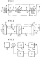
- The invention will now be described in further detail by way of example only and with reference to the accompanying drawings which show:
- Fig. 1 a schematic side view of a piezoelectric light deflecting apparatus in accordance with the invention,
- Fig. 2 a plan view of the subject of Fig. 1 and
- Fig. 3 a preferred circuit arrangement foroperating the light deflecting apparatus of Figs. 1 and 2.
- As seen in Figs. 1 and 2 two, first and second, piezoceramic
flexible strips blocks 20/that they lie in a plane with their free end faces facing one another and spaced apart by a small distance x. Theblocks 20 are fastened to a frame or housing and can be regarded as fixed structure. The first and secondflexible strips - As seen in Fig. 2 the two flexible strips are of substantially rectangular shape with the oppositely disposed
end faces 15 extending parallel to one another and spaced apart by the distance x. Theearth connections 21 for theflexible strips blocks 20 which face away from the free end faces 15. - It is important that the two
flexible strips blocks 20 and are polarized in opposite directions as is indicated by the oppositely directed arrows of Fig. 1. - Short,flexible,
synthetic legs 14 are fastened at right angles to theflexible strips end faces 15. The flexiblesynthetic legs 14 carry amirror 13 which is arranged at a distance above the slot between the twoflexible strips webs 14 are fixedly connected with the lower side of themirror 13 which is arranged symmetrically on thelegs 14. - The two
flexible strips electrodes 22 arranged on the upper and lower sides of theflexible strips central electrodes 21 which extend to theend faces 15 and which can be conveniently used to secure thesynthetic legs 14. - In this latter arrangement the
electrodes 21 are extended and are embedded inl or secured by adhesive to,thesynthetic legs 14. - A
feedback electrode 16 is arranged on and to one side of theflexible strip 11 and a feedback voltage URU can be tapped off between the feedback electrode and theelectrode 21. - As shown in Fig. 3 an electrical voltage, generated by a function generator 23/is applied via a
summing stage 24 and anamplifier part 17 between theelectrodes 22 of theflexible strips feedback electrode 16 will contain a mixture of frequencies which will include the mechanical natural frequency of the arrangement. The feedback voltage URÜ is passerl through acharge amplifier 18 to which is connected an all-pass filter 19. In thesumming stage 24 the delayed feedback signal is added to the output voltage of the function generator. - The manner of operation of the described apparatus is as follows:
- By applying the AC voltage U to the
flexible strips mirror 13 about an axis at right angles to the plane of Fig. 1. - A deflection of the piezoceramic
flexible strip 11 produces a change of the charge on thefeedback electrode 16. This is amplified by thecharge amplifier 18. The voltage at the output of thecharge amplifier 18 is a representation of the rotary oscillation of themirror 13 and indeed displaced by a transit time T. The function of the subsequent all-pass filter 19 is to delay the feedback signal. The delayed feedback signal is added to the input voltage of the function generator 23 in thesumming stage 24. The total delay time should be approximately half as large as the period of the mechanical natural frequency of oscillation. This results in a natural oscillation, excited for example by a step function such as a shock, being automatically quenched after a time T/2 where T is the period of the natural oscillation. - It will be appreciated by those skilled in the art that several variations can be made to the arrangement herein disclosed without departing from the scope of the present teaching. It is for example contemplated that the
mirror 13 can be oscillated by only a singlepiezoceramic strip 11. In this case the secondpiezoceramic strip 12 can be thought of as a fixed beam or rigid mounting. Clearly the amplitude of the oscillation will in this case not be as large as if the rigid beam 12.were also a flexible piezoceramic strip. - Finally it should be pointed out that the distance x is of importance and must be properly chosen in each particular arrangement. From a practical standpoint a reduction in the dimension x would lead to an increase in the amplitude of the rotary oscillation executed by the
mirror 13 assuming the deflection of the piezoceramic strips could be held constant. This is however not the case because a reduction in the distance x also increases the inertia of the arrangement which tends to reduce the amplitude of movement. Clearly a maximum amplitude of oscillation is achieved, for a given input, for a specific value of x which can be found in any particular case by calculation and/or experiment. - In one specific embodiment the following dimensions and materials were used to advantage:
- a) piezoceramic strips: material: "PxE5" material supplied by the Valvo company, size of each strip:
length 21 mm,width 19 mm, thickness 1 mm, separation of strips: x =1 mm; - b) mirror: rectangular glass mirror:
length 20 mm, width 10 mm, thickness 0.2 mm; - c) synthetic legs: 4 legs arranged two on each piezoceramic strip,length of each leg between top surface of the piezoceramic strips and the underside of the mirror 1.5 mm,width of each leg 2.5 mm thickness of each leg 0.1 mm;
- d) electrical and mechanical particulars: overall capacity of the two piezoceramic strips 55 nF, feedback capacity 4nF, Q factor of oscillation 60, natural resonant frequency 550 Hz, energising voltage: sawtooth waveform 50 Hz, resetting time ≤ 3 ms free of any noticeable resonant oscillation, proportionality factor 100 volt/° of mechanical deflection of one strip, total mechanical deflection + 3°.
Claims (10)
Applications Claiming Priority (2)
| Application Number | Priority Date | Filing Date | Title |
|---|---|---|---|
| DE3035315 | 1980-09-18 | ||
| DE3035315A DE3035315C2 (en) | 1980-09-18 | 1980-09-18 | Piezoelectric light deflection device |
Publications (3)
| Publication Number | Publication Date |
|---|---|
| EP0048364A2 true EP0048364A2 (en) | 1982-03-31 |
| EP0048364A3 EP0048364A3 (en) | 1982-06-16 |
| EP0048364B1 EP0048364B1 (en) | 1985-04-10 |
Family
ID=6112327
Family Applications (1)
| Application Number | Title | Priority Date | Filing Date |
|---|---|---|---|
| EP81106908A Expired EP0048364B1 (en) | 1980-09-18 | 1981-09-03 | Piezoelectric light deflecting apparatus |
Country Status (3)
| Country | Link |
|---|---|
| US (1) | US4436364A (en) |
| EP (1) | EP0048364B1 (en) |
| DE (1) | DE3035315C2 (en) |
Cited By (6)
| Publication number | Priority date | Publication date | Assignee | Title |
|---|---|---|---|---|
| EP0154865A1 (en) * | 1984-02-24 | 1985-09-18 | Firma Carl Zeiss | Position correcting device for a laser beam passing an articulated waveguide |
| EP0222202A2 (en) * | 1985-11-02 | 1987-05-20 | Firma Carl Zeiss | Electromagnetically controlled swing mirror |
| US4707596A (en) * | 1985-08-23 | 1987-11-17 | Carl-Zeiss-Stiftung | Articulated optical system having an arrangement for correcting the position of a laser beam |
| GB2241592A (en) * | 1990-02-13 | 1991-09-04 | William Henry Stevens | Scanning lasers for laser marking systems |
| WO2014048643A1 (en) * | 2012-09-27 | 2014-04-03 | Vermes Microdispensing GmbH | Dosing system, dosing method and production method |
| US10138916B2 (en) | 2012-09-27 | 2018-11-27 | Vermes Microdispensing GmbH | Dosing system, dosing method and production method |
Families Citing this family (19)
| Publication number | Priority date | Publication date | Assignee | Title |
|---|---|---|---|---|
| DE3213076A1 (en) * | 1982-04-07 | 1983-10-20 | Max Planck Gesellschaft zur Förderung der Wissenschaften e.V., 3400 Göttingen | SECONDARY MIRROR TILTING DEVICE FOR A MIRROR TELESCOPE |
| US4708420A (en) * | 1984-05-24 | 1987-11-24 | The Commonwealth Of Australia | Focal plane scanning device |
| AU571334B2 (en) * | 1984-05-24 | 1988-04-14 | Commonwealth Of Australia, The | Focal plane scanning device |
| US4691212A (en) * | 1985-11-14 | 1987-09-01 | Xerox Corporation | Piezoelectric optical beam deflector |
| US5514861A (en) * | 1988-05-11 | 1996-05-07 | Symbol Technologies, Inc. | Computer and/or scanner system mounted on a glove |
| US5410140A (en) * | 1988-05-11 | 1995-04-25 | Symbol Technologies, Inc. | Mirrorless ring mounted miniature optical scanner |
| US5170277A (en) * | 1988-05-11 | 1992-12-08 | Symbol Technologies, Inc. | Piezoelectric beam deflector |
| US5374817A (en) * | 1988-05-11 | 1994-12-20 | Symbol Technologies, Inc. | Pre-objective scanner with flexible optical support |
| US5245464A (en) * | 1988-08-12 | 1993-09-14 | Laser Scan Vision Aps | Deflecting instrument, controllable reflecting device herefor and use hereof |
| US5404001A (en) * | 1992-10-08 | 1995-04-04 | Bard; Simon | Fiber optic barcode reader |
| US5422469A (en) * | 1989-10-30 | 1995-06-06 | Symbol Technologies, Inc. | Fiber optic barcode readers using purely mechanical scanner oscillation |
| US5268784A (en) * | 1991-02-05 | 1993-12-07 | Canon Kabushiki Kaisha | Pivotable mirror device for tracking |
| FR2681407A1 (en) * | 1991-09-18 | 1993-03-19 | Angenieux P Ets | Beam lighting device |
| US5251056A (en) * | 1992-07-31 | 1993-10-05 | Eastman Kodak Company | High-speed light beam deflector |
| US5281812A (en) * | 1992-07-31 | 1994-01-25 | Eastman Kodak Company | Light beam scanning system including piezoelectric means for correction of cross scan error |
| US5903380A (en) * | 1997-05-01 | 1999-05-11 | Rockwell International Corp. | Micro-electromechanical (MEM) optical resonator and method |
| US20040003786A1 (en) * | 2002-06-18 | 2004-01-08 | Gatecliff George W. | Piezoelectric valve actuation |
| US6862122B1 (en) * | 2003-08-04 | 2005-03-01 | James Douglas Moore | High speed scanning or steering device |
| CN116448718B (en) * | 2023-04-19 | 2023-12-05 | 河北子曰机械设备有限公司 | Cavity ring-down tuning unit and cavity ring-down spectroscopy device |
Citations (5)
| Publication number | Priority date | Publication date | Assignee | Title |
|---|---|---|---|---|
| FR1054829A (en) * | 1951-01-26 | 1954-02-15 | Philips Nv | Device for converting electrical energy into mechanical vibratory energy |
| US3442570A (en) * | 1966-03-02 | 1969-05-06 | Hughes Aircraft Co | Piezoelectric laser beam deflector |
| DE2518347A1 (en) * | 1974-04-26 | 1975-11-06 | Secretary Industry Brit | DEVICE FOR GENERATING ANGLE VIBRATIONS |
| US3981566A (en) * | 1974-09-23 | 1976-09-21 | Eastman Kodak Company | Lever-action mountings for beam steerer mirrors |
| DE2950919A1 (en) * | 1978-12-14 | 1980-06-19 | Onera (Off Nat Aerospatiale) | IMPROVEMENTS TO VIBRATION DEVICES FOR THE TREATMENT OF AN OPTICAL BEAM |
Family Cites Families (1)
| Publication number | Priority date | Publication date | Assignee | Title |
|---|---|---|---|---|
| US3921045A (en) * | 1974-07-24 | 1975-11-18 | Bulova Watch Co Inc | Damped torsional rod oscillator |
-
1980
- 1980-09-18 DE DE3035315A patent/DE3035315C2/en not_active Expired
-
1981
- 1981-09-03 EP EP81106908A patent/EP0048364B1/en not_active Expired
- 1981-09-04 US US06/299,366 patent/US4436364A/en not_active Expired - Fee Related
Patent Citations (5)
| Publication number | Priority date | Publication date | Assignee | Title |
|---|---|---|---|---|
| FR1054829A (en) * | 1951-01-26 | 1954-02-15 | Philips Nv | Device for converting electrical energy into mechanical vibratory energy |
| US3442570A (en) * | 1966-03-02 | 1969-05-06 | Hughes Aircraft Co | Piezoelectric laser beam deflector |
| DE2518347A1 (en) * | 1974-04-26 | 1975-11-06 | Secretary Industry Brit | DEVICE FOR GENERATING ANGLE VIBRATIONS |
| US3981566A (en) * | 1974-09-23 | 1976-09-21 | Eastman Kodak Company | Lever-action mountings for beam steerer mirrors |
| DE2950919A1 (en) * | 1978-12-14 | 1980-06-19 | Onera (Off Nat Aerospatiale) | IMPROVEMENTS TO VIBRATION DEVICES FOR THE TREATMENT OF AN OPTICAL BEAM |
Non-Patent Citations (1)
| Title |
|---|
| APPLIED OPTICS, Vol. 18, No. 4, 1979, New York, J.K. LEE "Piezoelectric Bimorph Optical Beam Scanners: Analysis and Construction", pages 454 to 459 * |
Cited By (10)
| Publication number | Priority date | Publication date | Assignee | Title |
|---|---|---|---|---|
| EP0154865A1 (en) * | 1984-02-24 | 1985-09-18 | Firma Carl Zeiss | Position correcting device for a laser beam passing an articulated waveguide |
| US4707596A (en) * | 1985-08-23 | 1987-11-17 | Carl-Zeiss-Stiftung | Articulated optical system having an arrangement for correcting the position of a laser beam |
| EP0222202A2 (en) * | 1985-11-02 | 1987-05-20 | Firma Carl Zeiss | Electromagnetically controlled swing mirror |
| EP0222202A3 (en) * | 1985-11-02 | 1989-07-26 | Firma Carl Zeiss | Electromagnetically controlled swing mirror |
| GB2241592A (en) * | 1990-02-13 | 1991-09-04 | William Henry Stevens | Scanning lasers for laser marking systems |
| GB2241592B (en) * | 1990-02-13 | 1994-10-05 | William Henry Stevens | Improvements in or relating to laser marking arrangements |
| WO2014048643A1 (en) * | 2012-09-27 | 2014-04-03 | Vermes Microdispensing GmbH | Dosing system, dosing method and production method |
| CN104684656A (en) * | 2012-09-27 | 2015-06-03 | 微密斯点胶技术有限公司 | Dosing system, dosing method and production method |
| US9457935B2 (en) | 2012-09-27 | 2016-10-04 | Vermes Microdispensing GmbH | Dosing system, dosing method and production method |
| US10138916B2 (en) | 2012-09-27 | 2018-11-27 | Vermes Microdispensing GmbH | Dosing system, dosing method and production method |
Also Published As
| Publication number | Publication date |
|---|---|
| US4436364A (en) | 1984-03-13 |
| DE3035315A1 (en) | 1982-04-01 |
| EP0048364A3 (en) | 1982-06-16 |
| EP0048364B1 (en) | 1985-04-10 |
| DE3035315C2 (en) | 1984-07-12 |
Similar Documents
| Publication | Publication Date | Title |
|---|---|---|
| US4436364A (en) | Piezoelectric apparatus for producing rotary oscillation of a mirror | |
| US4489609A (en) | Gyroscopes | |
| US4780062A (en) | Piezoelectric fan | |
| US4321500A (en) | Longitudinal isolation system for flexurally vibrating force transducers | |
| DE69325101D1 (en) | STABILIZED, TACTICAL, ELECTROMAGNETIC SWINGARM (VIBRATOR) WITH RESON ANCHOR | |
| US4831370A (en) | Vibrating fiber optic display having a resonant ribbon driver | |
| GB1254037A (en) | Ultrasonic transducer employing suspended piezoelectric plate | |
| US2928052A (en) | Transducer power supply for oscillators | |
| US3666974A (en) | Torsional fork transducers | |
| EP0369572A2 (en) | Sieving apparatus | |
| JPS6059900A (en) | Piezoelectric vibrator using buckling spring | |
| JPH07170768A (en) | Ultrasonic motor | |
| JPH06105571A (en) | Ultrasonic linear motor and manufacture thereof | |
| US3636810A (en) | Tuning forks and oscillators embodying the same | |
| GB2111209A (en) | Piezoelectric oscillatory gyroscopes | |
| GB2026284A (en) | Seismic transducer | |
| RU2030343C1 (en) | Oscillating conveyer | |
| US2735025A (en) | Piezoelectric device | |
| JPS59175777A (en) | Method for driving bimorph vibrator | |
| JPS5825214B2 (en) | Powder level detection device | |
| JPH0541823Y2 (en) | ||
| SU1551430A1 (en) | Vibration device | |
| US3742387A (en) | Multi frequency mass spring oscillators | |
| SU1622024A1 (en) | Piezoelectric transducer | |
| JPH03212175A (en) | Linear ultrasonic wave motor |
Legal Events
| Date | Code | Title | Description |
|---|---|---|---|
| PUAI | Public reference made under article 153(3) epc to a published international application that has entered the european phase |
Free format text: ORIGINAL CODE: 0009012 |
|
| 17P | Request for examination filed |
Effective date: 19810903 |
|
| AK | Designated contracting states |
Designated state(s): FR GB IT |
|
| PUAL | Search report despatched |
Free format text: ORIGINAL CODE: 0009013 |
|
| AK | Designated contracting states |
Designated state(s): FR GB IT |
|
| ITF | It: translation for a ep patent filed |
Owner name: BARZANO' E ZANARDO MILANO S.P.A. |
|
| GRAA | (expected) grant |
Free format text: ORIGINAL CODE: 0009210 |
|
| AK | Designated contracting states |
Designated state(s): FR GB IT |
|
| ET | Fr: translation filed | ||
| PLBE | No opposition filed within time limit |
Free format text: ORIGINAL CODE: 0009261 |
|
| STAA | Information on the status of an ep patent application or granted ep patent |
Free format text: STATUS: NO OPPOSITION FILED WITHIN TIME LIMIT |
|
| 26N | No opposition filed | ||
| PG25 | Lapsed in a contracting state [announced via postgrant information from national office to epo] |
Ref country code: GB Effective date: 19890903 |
|
| GBPC | Gb: european patent ceased through non-payment of renewal fee | ||
| PG25 | Lapsed in a contracting state [announced via postgrant information from national office to epo] |
Ref country code: FR Effective date: 19900531 |
|
| REG | Reference to a national code |
Ref country code: FR Ref legal event code: ST |