EP0050085A1 - Electric handle switch for motor-cycles and the like - Google Patents
Electric handle switch for motor-cycles and the like Download PDFInfo
- Publication number
- EP0050085A1 EP0050085A1 EP81420143A EP81420143A EP0050085A1 EP 0050085 A1 EP0050085 A1 EP 0050085A1 EP 81420143 A EP81420143 A EP 81420143A EP 81420143 A EP81420143 A EP 81420143A EP 0050085 A1 EP0050085 A1 EP 0050085A1
- Authority
- EP
- European Patent Office
- Prior art keywords
- carriage
- longitudinal
- housing
- transverse
- tracks
- Prior art date
- Legal status (The legal status is an assumption and is not a legal conclusion. Google has not performed a legal analysis and makes no representation as to the accuracy of the status listed.)
- Withdrawn
Links
Images

Classifications
-
- B—PERFORMING OPERATIONS; TRANSPORTING
- B62—LAND VEHICLES FOR TRAVELLING OTHERWISE THAN ON RAILS
- B62K—CYCLES; CYCLE FRAMES; CYCLE STEERING DEVICES; RIDER-OPERATED TERMINAL CONTROLS SPECIALLY ADAPTED FOR CYCLES; CYCLE AXLE SUSPENSIONS; CYCLE SIDE-CARS, FORECARS, OR THE LIKE
- B62K11/00—Motorcycles, engine-assisted cycles or motor scooters with one or two wheels
- B62K11/14—Handlebar constructions, or arrangements of controls thereon, specially adapted thereto
-
- B—PERFORMING OPERATIONS; TRANSPORTING
- B62—LAND VEHICLES FOR TRAVELLING OTHERWISE THAN ON RAILS
- B62J—CYCLE SADDLES OR SEATS; AUXILIARY DEVICES OR ACCESSORIES SPECIALLY ADAPTED TO CYCLES AND NOT OTHERWISE PROVIDED FOR, e.g. ARTICLE CARRIERS OR CYCLE PROTECTORS
- B62J6/00—Arrangement of optical signalling or lighting devices on cycles; Mounting or supporting thereof; Circuits therefor
- B62J6/16—Arrangement of switches
-
- H—ELECTRICITY
- H01—ELECTRIC ELEMENTS
- H01H—ELECTRIC SWITCHES; RELAYS; SELECTORS; EMERGENCY PROTECTIVE DEVICES
- H01H25/00—Switches with compound movement of handle or other operating part
- H01H25/06—Operating part movable both angularly and rectilinearly, the rectilinear movement being along the axis of angular movement
-
- H—ELECTRICITY
- H01—ELECTRIC ELEMENTS
- H01H—ELECTRIC SWITCHES; RELAYS; SELECTORS; EMERGENCY PROTECTIVE DEVICES
- H01H9/00—Details of switching devices, not covered by groups H01H1/00 - H01H7/00
- H01H9/02—Bases, casings, or covers
- H01H9/06—Casing of switch constituted by a handle serving a purpose other than the actuation of the switch, e.g. by the handle of a vacuum cleaner
- H01H2009/068—Casing of switch constituted by a handle serving a purpose other than the actuation of the switch, e.g. by the handle of a vacuum cleaner with switches mounted on a handlebar, e.g. for motorcycles, fork lift trucks, etc.
Definitions
- the present invention relates to an electric handle switch placed on the handlebars of motorized two-wheeled vehicles, such as mopeds and motorcycles, and usually associated with the left handlebar handle.
- the conventional electric controls grouped together on the handlebars of a vehicle of this type are, on the one hand, the lighting control with two levels of illumination, dipped beam headlights and, on the other hand, the control direction indicator lights. In addition to these functions, there is usually the horn control.
- buttons are controlled from separate buttons, sometimes distant from each other on the handlebars, which increases the total size of the electrical controls and makes manual actuation difficult, in particular with gloves.
- US Patent 4,191,866 describes a three-function switch comprising a housing in which two carriages, rocking around orthogonal axes, are able, under the action of a control button crossing the face of the housing and also ensuring the control of the horn, to move the switching brushes, to bring them on one or the other of the fixed studs that respectively comprise the housing and one of the carriages, to control the lighting and direction change indicators.
- These pads are formed at the end of metal bars which, like the brushes and contact pads of the horn, are connected to the various control and supply circuits by flexible wires.
- the object of the present invention is to remedy these various drawbacks by providing a device allowing the integration in a single housing of all the electrical controls necessary for the vehicle's service functions by using inexpensive and reliable means.
- This device is of the type composed of a housing which can be attached to the handlebars of the vehicle and a control button which can be moved through an opening in the housing to control specific functions by means of intermediate carriages carrying contact means capable of cooperating, according to their position, indexed or not, with electrical contact means distributed in the housing.
- the intermediate carriages of the sliding type in perpendicular and, respectively, transverse and longitudinal directions, each comprise at least one junction slider capable of cooperating with fixed conductive tracks which, having the exclusive functions of supply and distribution, are flush with the face opposite the corresponding cursor and form part of bars embedded in fixed elements of the handle and leading to areas of junction with conductors, the tracks for the transverse carriage being longitudinal, continuous, spaced transversely and in the plane of the internal face of the housing which is in frictional contact with this carriage, while the tracks for the longitudinal carriage are transverse, spaced longitudinally and in the plane of a face in contact with the cursor , face which is carried out on an integral collar of the housing.
- the carriages are stripped of all electrical connections. They therefore operate very reliably over time and only offer low friction resistances to their handling by the single control button.
- mode of connection associated with the use of carriages having perpendicular sliding movements makes it possible to increase the number of tracks and the number of functions controlled by a carriage without increasing the overall size of the switch and without altering the possibility of combinations of positions of the two carts.
- the longitudinal carriage is integral with two lateral sliders and has a central groove cooperating with a longitudinal rib which, projecting from the internal collar of the handle, separates two friction faces each provided with suitable tracks to cooperate with the aforesaid sliders, tan - say that the transverse carriage is provided with a groove to ensure its association with the longitudinal slide and guiding in translation, between the latter and the housing, cooperating with a transverse rib of the longitudinal carriage .
- This arrangement ensures the connection and guiding of the carriages by simple and space-saving means making it possible to increase the number of tracks if necessary.
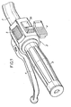
- FIG. 1 shows the left end of a handlebar 1 of a moped provided with a handle proper 2 and with a block 3 on which the brake lever 4 is pivotally mounted.
- Block 3 supports the electrical switch making more particularly the object of the invention, the control of the horn with its push button 5, and the decompression lever 6.
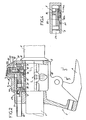
- the block 3 is composed of an outer casing formed by two adjoining half-shells 7 and 8. It further comprises an internal collar 9 linked to the half-shell 8 by screws 10 visible in FIGS. 2 and 5. The tightening these screws 10 ensures that the block 3 is held on the handlebar tube 1 which passes right through it.
- a bundle of electrical wires 11 surrounded by a sheath 12 leads to the block 3 and penetrates into junction zones, respectively rear 29 and lateral 30 formed between the half-shell 7 and the collar 9.
- the collar 9 has a central longitudinal rib 13 projecting and bordered by two friction faces 9a and 9b. This rib cooperates with a groove 14a of a longitudinal carriage 14 for guiding in translation of the latter a ball 15, disposed in a housing of the carriage 14 and pushed by a spring 16, ensures the indexing of this carriage in a central position by engaging in a cavity formed in the collar 9.
- the longitudinal carriage 14 serves as a support and guide for a transverse carriage 17 movable along a path in a slight arc of circle entre.ce longitudinal carriage 14 and the half-shell 7.
- the longitudinal carriage 14 has a transverse rib 14b , visible in FIG. 2, cooperating with a groove 17a of the transverse carriage 17.
- the transverse carriage 17 is integral with a head 21 which passes through the half-shell 7 through an opening 22 to receive an external control button 23 to which it is linked by a pin 24.
- This control button is bulky so that it can be actuated even with gloves and to completely close the opening 22, whatever its position, and thus ensure the tightness of the shoemaker.
- the combination of the movements of the two carriages makes it possible to obtain a number of positions equal to the product of the number of positions of each of the carriages.
- the two carriages each having three positions, it is therefore possible to obtain nine positions.
- the longitudinal displacement of the control button 23 and of the carriage 14 via that 17, is used for the control of the direction change indicator lights.
- the carriage 14 is integral with two sliders 25, of electrical junction, cooperating with fixed conductive tracks, respectively, of supply 26a and distribution 26b. These tracks are flush with each of the faces 9a and 9b of the collar 9 in contact with the sliders 25. These tracks constitute one of the ends of conductive bars 31 embedded in the collar 9 and connected by their other end to the corresponding electrical wires 11 ending in, as shown in FIG. 5, in the lateral junction zone 30.
- the tracks 26a and 26b are transverse and longitudinally spaced, those. 26a being wider than those 26b for supplying the latter in the two extreme positions of the longitudinal carriage 14. In this way, when the button 23 is in the central position, indexed by the ball 15, the direction change indicators are not supplied, while when in one or other of its extreme positions, the cursor provides the electrical junction between the supply track 26a and the corresponding distribution track 26b.
- the carriage 14 has a second cursor and associated tracks to ensure a differentiated control of the direction change indicators, respectively front and rear.
- the transverse movement of the button 23 and the transverse carriage 17 is used to control the lighting and select its power.
- the carriage 17 carries a junction cursor 27, visible in FIG. 2 and especially in FIG. 5, cooperating with conductive tracks fixed, supply 28a and distribution 28b respectively.
- These tracks which are flush with the internal face of the half-shell 7, are formed by one of the faces of bars 32 embedded in the shell and whose posterior ends are connected to the corresponding wires 11 in the rear junction zone 29 of the housing.
- the tracks 28a and 28b are longitudinal, continuous and spaced transversely, that 28a being wider than that 28b, so as to allow one or the other of these to be fed by the junction slider 27 for two of the positions of the latter.
- the tracks are arranged the relative to each other so that, to an extreme position of the button 23 and carriage 17,1'éclairage is not in operation, and that for the intermediate position and the other extreme position of this button i lighting is in operation and, respectively, in the low beam and high beam positions.
- continuous tracks 28a and 28b makes it possible to ensure the consistency of the functions determined by the transverse position of the carriage 17, whatever the variations in its longitudinal position, therefore whatever the position of the control of the change indicators of direction.
- the housing has, on its outer face, marks and symbols facilitating the identification of the functions performed in the various positions of the button 23.
- This device which has been described in the case of its application to the satisfaction of six functions, namely: absence of flashing, right flashing, left flashing, absence of lighting, lighting in low beam, lighting in high beam, these functions can be cumulated through nine positions, can also satisfy additional functions, such as: night light, call for high beam, switching on night or daytime accessories. To do this, simply add one or more tracks distribution in the path of one of the sliders, without this affecting the size of the box and the reliability of the switch.
Abstract
Description
La présente invention a pour objet un commutateur électrique de poignée placé sur le guidon de véhicules motorisés à deux roues,tels que cyclomoteurs et motocyclettes,et habituellement associé à la poignée gauche du guidon.The present invention relates to an electric handle switch placed on the handlebars of motorized two-wheeled vehicles, such as mopeds and motorcycles, and usually associated with the left handlebar handle.
Les commandes électriques classiques regroupées sur le guidon d'un véhicule de ce type sont,d'une part,la commande d'éclairage avec deux niveaux d'éclairement,feux de croisement -feux de route et,d'autre part,la commande des feux indicateurs des changements de direction. A ces fonctions s'ajoute généralement la commande de l'avertisseur sonore .The conventional electric controls grouped together on the handlebars of a vehicle of this type are, on the one hand, the lighting control with two levels of illumination, dipped beam headlights and, on the other hand, the control direction indicator lights. In addition to these functions, there is usually the horn control.
Le plus souvent,ces diverses fonctions électriques sont commandées à partir de boutons distincts parfois éloignés les uns des autres sur le guidon,ce qui augmente l'encombrement total des commandes électriques et rend difficile leur actionnement manuel,en particulier avec des gants.Most often, these various electrical functions are controlled from separate buttons, sometimes distant from each other on the handlebars, which increases the total size of the electrical controls and makes manual actuation difficult, in particular with gloves.
Pour remédier à cela,le brevet américain 4.191.866 décrit un interrupteur à trois fonctions comprenant un boîtier dans lequel deux chariots,basculant autour d'axes orthogonaux,sont en mesure,sous l'action d'un bouton de commande traversant la face du boîtier et assurant aussi la commande d'avertisseur sonore,de déplacer des balais de commutation,pour les amener sur l'un ou l'autre des plots fixes que comportent respectivement le boîtier et l'un des chariots,pour commander les fonctions éclairage et indicateurs de changement de direction.Ces plots sont formés à l'extrémité de barrettes métalliques qui,comme les balais et les plots de contact de l'avertisseur,sont raccordées aux divers circuits de commande et d'alimentation par des fils souples. Le recours à ces derniers pour relier les contacts des chariots basculants, apporte deux inconvénients:le premier provient du fait que,quelle que soit la souplesse des conducteurs,ces derniers,d'une part, exercent une résistance lors de la manipulation du bouton de commande et,d'autre part,peuvent se sectionner après de nombreuses manipulations; le second résulte de l'encombrement de ces moyens de jonction,encombrement qui limite le nombre de conducteurs de jonction pouvant être disposés dans le boitier,donc réduit le nombre de positions du bouton et le nombre de fonctions pouvant être commandées. Ainsi,par exemple,dans le dispositif de ce brevet américain,la mise en service des fonctions éclairage est réalisée par un interrupteur indépendant et hors du boîtier.To remedy this, US Patent 4,191,866 describes a three-function switch comprising a housing in which two carriages, rocking around orthogonal axes, are able, under the action of a control button crossing the face of the housing and also ensuring the control of the horn, to move the switching brushes, to bring them on one or the other of the fixed studs that respectively comprise the housing and one of the carriages, to control the lighting and direction change indicators. These pads are formed at the end of metal bars which, like the brushes and contact pads of the horn, are connected to the various control and supply circuits by flexible wires. The use of the latter to connect the contacts of the tilting carriages brings two drawbacks: the first arises from the fact that, whatever the flexibility of the conductors, the latter, on the one hand, exert resistance when handling the button command and, on the other hand, can be cut after many manipulations; the second results from the size of these junction means, space which limits the number of junction conductors that can be arranged in the housing, therefore reduces the number of button positions and the number of functions that can be controlled. Thus, for example, in the device of this American patent, the lighting functions are put into service by an independent switch and outside the housing.
La présente invention a pour but de remédier à ces divers inconvénients en fournissant un dispositif permettant l'intégration dans un même boîtier de toutes les commandes électriques nécessaires aux fonctions de service du véhicule en utilisant des moyens peu onéreux et fiables.The object of the present invention is to remedy these various drawbacks by providing a device allowing the integration in a single housing of all the electrical controls necessary for the vehicle's service functions by using inexpensive and reliable means.
Ce dispositif est du type composé d'un boîtier rapportable sur le guidon du véhicule et d'un bouton de commande déplaçable à travers une ouverture du boîtier pour commander des fonctions spécifiques au moyen de chariots intermédiaires portant des moyens de contact aptes à coopérer,selon leur position,indexée ou non,avec des moyens de contact électrique répartis dans le boîtier.This device is of the type composed of a housing which can be attached to the handlebars of the vehicle and a control button which can be moved through an opening in the housing to control specific functions by means of intermediate carriages carrying contact means capable of cooperating, according to their position, indexed or not, with electrical contact means distributed in the housing.
Selon l'invention,les chariots intermédiaires,de type coulissant suivant des directions perpendiculaires et, respectivement, transversal et longitudinal, comportent chacun au moins un curseur de jonction apte à coopérer avec des pistes conductrices fixes qui,ayant l'exclusivité des fonctions d'alimentation et de distribution, affleurent la face en vis-à-vis du curseur correspondant et font partie de barrettes noyées dans des éléments fixes de la poignée et aboutissant à des zones de jonction avec des conducteurs ,les pistes pour le chariot transversal étant longitudinales,continues,espacées transversalement et dans le plan de la face interne du boîtier qui est en contact de frottement avec ce chariot,tandis que les pistes pour le chariot longitudinal sont transversales,espacées longitudinalement et dans le plan d'une face de contact avec le curseur,face qui est réalisée sur un collier solidaire du boîtier.According to the invention, the intermediate carriages, of the sliding type in perpendicular and, respectively, transverse and longitudinal directions, each comprise at least one junction slider capable of cooperating with fixed conductive tracks which, having the exclusive functions of supply and distribution, are flush with the face opposite the corresponding cursor and form part of bars embedded in fixed elements of the handle and leading to areas of junction with conductors, the tracks for the transverse carriage being longitudinal, continuous, spaced transversely and in the plane of the internal face of the housing which is in frictional contact with this carriage, while the tracks for the longitudinal carriage are transverse, spaced longitudinally and in the plane of a face in contact with the cursor , face which is carried out on an integral collar of the housing.
Grâce au recours,d'une part,à des pistes conductrices fixes assurant à la fois,mais séparément,la fonction d'alimentation,c'est-à-dire d'amenée du courant et de distribution,c'est-à-dire d'alimentation d'une fonction et, d'autre part,à des curseurs n'assurant que la fonction de jonction,c'est-à-dire de mise en communication de l'une des pistes d'alimentation avec l'une des pistes de distribution,les chariots sont débarrassés de toutes connexions électriques.Ils ont donc un fonctionnement très fiable dans le temps et n'opposent que de faibles résistances de frottement à leurs manipulations par l'unique bouton de commande.Par ailleurs,ce mode de connexion ,associé à l'utilisation de chariots ayant des déplacements coulissants perpendiculaires permet d'augmenter le nombre de pistes et le nombre de fonctions commandées par un chariot sans augmenter l'encombrement général du commutateur et sans altérer la possibilité de combinaisons des positions des deux chariots.Thanks to the use, on the one hand, of fixed conductive tracks ensuring both, but separately, the power supply function, that is to say current supply and distribution, that is to say to say supplying a function and, on the other hand, to sliders ensuring only the junction function, that is to say of putting one of the supply tracks in communication with the one of the distribution tracks, the carriages are stripped of all electrical connections. They therefore operate very reliably over time and only offer low friction resistances to their handling by the single control button. mode of connection, associated with the use of carriages having perpendicular sliding movements makes it possible to increase the number of tracks and the number of functions controlled by a carriage without increasing the overall size of the switch and without altering the possibility of combinations of positions of the two carts.
Dans une forme d'exécution de l'invention,le chariot longitudinal est solidaire de deux curseurs latéraux et comporte une rainure centrale coopérant avec une nervure longitudinale qui,saillant du collier interne de la poignée,sépare deux faces de frottement munies chacune de pistes aptes à coopérer avec les curseurs précités,tan- dis que le chariot transversal est muni d'une rainure assurant sa liaison avec le chariot longitudinal et son guidage en translation, entre ce dernier et le boîtier,en coopérant avec une nervure transversale de ce chariot longitudinal.In one embodiment of the invention, the longitudinal carriage is integral with two lateral sliders and has a central groove cooperating with a longitudinal rib which, projecting from the internal collar of the handle, separates two friction faces each provided with suitable tracks to cooperate with the aforesaid sliders, tan - say that the transverse carriage is provided with a groove to ensure its association with the longitudinal slide and guiding in translation, between the latter and the housing, cooperating with a transverse rib of the longitudinal carriage .
Cet agencement assure la liaison et le guidage des chariots par des moyens simples et peu encombrants permettant d'augmenter le nombre de pistes si besoin est.This arrangement ensures the connection and guiding of the carriages by simple and space-saving means making it possible to increase the number of tracks if necessary.
De toute façon,l'invention sera mieux comprise à l'aide de la description qui suit,en référence au dessin schématique annexé représentant,à titre d'exemple non limitatif,une forme d'exécution de ce commutateur électrique de poignée dans le cas où son bouton de commande peut occuper neuf positions:
- Figure 1 est une vue générale ,en perspective,d'une poignée de cyclomoteur,équipée de commutateur selon l'invention,
- Figure 2 est une vue partielle,en coupe longitudinale, de la poignée de figure 1,montrant la structure interne de ce commutateur électrique,
- Figure 3 en est une vue en coupe transversale suivant 3-3 de fig.2;
- Figure 4 en est une coupe longitudinale partielle, suivant 4-4 de figure 3;
- Figure 5 en est une coupe transversale suivant 5-5 de figure 3.
- FIG. 1 is a general perspective view of a handle of a moped, fitted with a switch according to the invention,
- FIG. 2 is a partial view, in longitudinal section, of the handle of FIG. 1, showing the internal structure of this electrical switch,
- Figure 3 is a cross-sectional view along 3-3 of fig.2;
- Figure 4 is a partial longitudinal section along 4-4 of Figure 3;
- Figure 5 is a cross section along 5-5 of Figure 3.
La figure 1 montre l'extrémité gauche d'un guidon 1 de cyclomoteur munie d'une poignée proprement dite 2 et d'un bloc 3 sur lequel est monté pivotant le levier de frein 4. Le bloc 3 supporte le commutateur électrique faisant plus particulièrement l'objet de l'invention,la commande de l'avertisseur sonore avec son bouton-poussoir 5,et la manette de décompression 6.FIG. 1 shows the left end of a handlebar 1 of a moped provided with a handle proper 2 and with a block 3 on which the brake lever 4 is pivotally mounted. Block 3 supports the electrical switch making more particularly the object of the invention, the control of the horn with its
Le bloc 3 est composé d'un boîtier extérieur formé par deux demi-coquilles accolées 7 et 8. Il comprend,en outre, un collier interne 9 lié à la demi-coquille 8 par des vis 10 visibles aux figures 2 et 5. Le serrage de ces vis 10 assure la tenue du bloc 3 sur le tube du guidon 1 qui le traverse de part en part.Un faisceau de fils électriques 11 entourés d'une gaine 12 aboutit au bloc 3 et pénètre dans des zones de jonction,respectivement postérieure 29 et latérale 30 ménagées entre la demi-coquille 7 et le collier 9.The block 3 is composed of an outer casing formed by two adjoining half-
Le collier 9 comporte une nervure longitudinale centrale 13 formant saillie et bordée par deux faces de frottement 9a et 9b. Cette nervure coopère avec une rainure 14a d'un chariot longitudinal 14 pour assurer le guidage en translation de celui-cioUne bille 15,disposée dans un logement du chariot 14 et poussée par un ressort 16,assure l'indexation de ce chariot dans une position centrale en s'engageant dans une cavité ménagée dans le collier 9.The
Le chariot longitudinal 14 sert de support et de guide à un chariot transversal 17 déplaçable suivant une trajectoire en léger arc de cercle entre.ce chariot longitudinal 14 et la demi-coquille 7.A cet effet,le chariot longitudinal 14 comporte une nervure transversale 14b,visible figure 2,coopérant avec une rainure 17a du chariot transversal 17. Une bille 18,disposée dans un logement débouchant dans la rainure 17a du chariot 17 et poussée par un ressort, assure l'indexation de ce chariot transversal 17 dans trois positions en s'engageant dans l'une ou l'autre des cavités 20 ménagées dans le chariot longitudinal 14.The
Le chariot transversal 17 est solidaire d'une tête 21 qui traverse la demi-coquille 7 par une ouverture 22 pour recevoir un bouton de commande extérieur 23 auquel elle est liée par une goupille 24. Ce bouton de commande est volumineux pour pouvoir être actionné même avec des gants et pour obturer totalement l'ouverture 22,quelle que soit sa position,et assurer ainsi l'étanchéité du bottier.The transverse carriage 17 is integral with a head 21 which passes through the half-
La combinaison des déplacements des deux chariots permet d'obtenir un nombre de positions égal au produit du nombre de positions de chacun des chariots.Dans cette forme d'exécution,les deux chariots ayant chacun trois positions,il est donc possible d'obtenir neuf positions.The combination of the movements of the two carriages makes it possible to obtain a number of positions equal to the product of the number of positions of each of the carriages. In this embodiment, the two carriages each having three positions, it is therefore possible to obtain nine positions.
Dans cette forme d'exécution,le déplacement longitudinal du bouton de commande 23 et du chariot 14 par l'intermédiaire de celui 17,est utilisé pour la commande des feux indicateurs de changement de direction. A cet effet,Le chariot 14 est solidaire de deux curseurs 25,de jonction électrique,coopérant avec des pistes conductrices fixes, respectivement,d'alimentation 26a et de distribution 26b. Ces pistes affleurent chacune des faces 9a et 9b du collier 9 en contact avec les curseurs 25. Ces pistes constituent l'une des extrémités de barrettes conductrices 31 noyées dans le collier 9 et raccordées par leur autre extrémité aux fils électriques 11 correspondants aboutissant, comme montré à la figure 5,dans la zone de jonction latérale 30.Comme montré figure 4,les pistes 26a et 26b sont transversales et espacées longitudinalement,celles. 26a étant plus larges que celles 26b pour assurer l'alimentation de ces dernières dans les deux positions extrêmes du chariot longitudinal 14. De la sorte,lorsque le bouton 23 est en position centrale,indexée par la bille 15,les indicateurs de changement de direction ne sont pas alimentés, tandis que lorsqu'il est dans l'une ou l'autre de ses positions extrêmes,le curseur assure la jonction électrique entre la piste d'alimentation 26a et la piste de distribution correspondante 26b.In this embodiment, the longitudinal displacement of the
Il est à noter que,grâce à sa structure et,notamment à l'utilisation de pistes fixes dont la liaison avec la source de courant et les organes commandés est assurée par des barrettes noyées,il est possible d'augmenter ce nombre de pistes sans augmenter considérablement l'encombrement.Ainsi,dans la forme d'exécution représentée ,et alors même qu'un agent curseur 25 et des pistes correspondantes sont en général suffisants pour commander les indicateurs de changement de direction,le chariot 14 comporte un deuxième curseur et des pistes associées pour assurer une commande différenciée des indicateurs de changement de direction,respectivement avant et arrière.It should be noted that, thanks to its structure and, in particular to the use of fixed tracks whose connection with the current source and the controlled organs is ensured by embedded bars, it is possible to increase this number of tracks without considerably increase the overall dimensions. Thus, in the embodiment shown, and even when a
Le déplacement transversal du bouton 23 et du chariot transversal 17 est utilisé pour commander l'éclairage et sélectionner sa puissance.A cet effet,le chariot 17 porte un curseur de jonction 27,visible figure 2 et surtout figure 5,coopérant avec des pistes conductrices fixes,respectivement d'alimentation 28a et de distribution 28b.Ces pistes,qui affleurent la face interne de la demi-coquille 7,sont formées par l'une des faces de barrettes 32 noyées dans la coquille et dont les extrémités postérieures sont raccordées aux fils 11 correspondants dans la zone de jonction postérieure 29 du boîtier.Comme montré figure 5,les pistes 28a et 28b sont longitudinales, continues et espacées transversalement, celle 28a étant plus large que celle 28b ,de manière a permettre l'alimentation de l'une ou l'autre de ces dernières par le curseur de jonction 27 pour deux des positions de ce dernier.Dans cette forme d'exécution,les pistes sont disposées les unes par rapport aux autres de manière que,pour une position extrême du bouton 23 et du chariot 17,1'éclairage ne soit pas en fonction,et que pour la position intermédiaire et l'autre position extrême de ce boutonil'éclairage soit en fonction et,respectivement,dans les positions feux de croisement et feux de route.The transverse movement of the
L'utilisation de pistes 28a et 28b continues permet d'assurer la constance des fonctions déterminées par la position transversale du chariot 17,quelles que soient les variations de sa position longitudinale,donc quelle que soit la position de la commande des indicateurs de changement de direction.The use of continuous tracks 28a and 28b makes it possible to ensure the consistency of the functions determined by the transverse position of the carriage 17, whatever the variations in its longitudinal position, therefore whatever the position of the control of the change indicators of direction.
Bien entendu,le boîtier comporte,sur sa face extérieure,des repères et symboles facilitant l'identification des fonctions assurées dans les diverses positions du bouton 23.Of course, the housing has, on its outer face, marks and symbols facilitating the identification of the functions performed in the various positions of the
Ce dispositif,qui a été décrit dans le cas de son application à la satisfaction de six fonctions,à savoir: absence de clignotement,clignotement droit,clignotement gauche,absence d'éclairage,éclairage en feux de croisement,éclairage en feux de route,ces fonctions se cumulant à travers neuf positions,peut aussi satisfaire des fonctions supplémentaires,telles que:éclairage en veilleuse, appel en feux de route,mise en route d'accessoires nocturnes ou diurnes.Pour cela,il suffit de rajouter une ou plusieurs pistes de distribution dans la trajectoire de l'un des curseurs,sans que cela intervienne sur l'encombrement du boitier et sur la fiabilité du commutateur.This device, which has been described in the case of its application to the satisfaction of six functions, namely: absence of flashing, right flashing, left flashing, absence of lighting, lighting in low beam, lighting in high beam, these functions can be cumulated through nine positions, can also satisfy additional functions, such as: night light, call for high beam, switching on night or daytime accessories. To do this, simply add one or more tracks distribution in the path of one of the sliders, without this affecting the size of the box and the reliability of the switch.
En outre,toutes les liaisons électriques de ce commutateur sont assurées par déplacement avec frottement de curseurs,donc par des moyens assurant l'auto-nettoyage des contacts à chaque mouvement du bouton,évitant ainsi le charbonnage de ces contacts,comme cela se produit dans les dispositifs où les liaisons électriques sont assurées par simple pression de contact.Ce mode de liaison par balayage de contact permet donc d'obtenir la fiabilité de la commutation.In addition, all the electrical connections of this switch are ensured by sliding with friction of sliders, therefore by means ensuring the self-cleaning of the contacts with each movement of the button, thus avoiding the smearing of these contacts, as occurs in devices where the electrical connections are made by simple contact pressure. This mode of contact scan sweeping therefore makes switching reliability possible.
Enfin,le rassemblement sur une même poignée,des commandes de toutes les fonctions électriques du cyclomoteur, permet d'avoir recours à un unique faisceau électrique ,donc contribue à la réduction du coût de fabrication du véhicule et à l'amélioration de son esthétique.Finally, the gathering on the same handle, of the controls of all the electrical functions of the moped, makes it possible to have recourse to a single electrical harness, therefore contributes to the reduction of the manufacturing cost of the vehicle and to the improvement of its aesthetics.
Claims (3)
Applications Claiming Priority (2)
| Application Number | Priority Date | Filing Date | Title |
|---|---|---|---|
| FR8022197A FR2492156A1 (en) | 1980-10-14 | 1980-10-14 | ELECTRIC HANDLE SWITCH FOR MOPEDS, MOTORCYCLES AND THE LIKE |
| FR8022197 | 1980-10-14 |
Publications (1)
| Publication Number | Publication Date |
|---|---|
| EP0050085A1 true EP0050085A1 (en) | 1982-04-21 |
Family
ID=9246994
Family Applications (1)
| Application Number | Title | Priority Date | Filing Date |
|---|---|---|---|
| EP81420143A Withdrawn EP0050085A1 (en) | 1980-10-14 | 1981-10-08 | Electric handle switch for motor-cycles and the like |
Country Status (4)
| Country | Link |
|---|---|
| EP (1) | EP0050085A1 (en) |
| ES (1) | ES261178Y (en) |
| FR (1) | FR2492156A1 (en) |
| MA (1) | MA19302A1 (en) |
Cited By (8)
| Publication number | Priority date | Publication date | Assignee | Title |
|---|---|---|---|---|
| EP0412418A2 (en) * | 1989-08-11 | 1991-02-13 | Gebr. Happich GmbH | Stop request button |
| GB2254734A (en) * | 1991-03-22 | 1992-10-14 | Asahi Optical Co Ltd | Switch for a zoom lens camera |
| EP0805099A2 (en) * | 1996-05-03 | 1997-11-05 | Domino S.p.A. | Switch for controlling direction indicators for motorcycles |
| ES2123356A1 (en) * | 1993-12-28 | 1999-01-01 | Honda Motor Co Ltd | Switch device for vehicle |
| DE19836298A1 (en) * | 1998-08-11 | 2000-02-17 | Bayerische Motoren Werke Ag | Electrical switch combination |
| FR2812611A1 (en) * | 2000-08-07 | 2002-02-08 | Honda Motor Co Ltd | MOUNTING STRUCTURE OF A HANDLEBAR SWITCH |
| EP1232941A3 (en) * | 2001-02-15 | 2005-01-19 | Shimano Inc. | Bicycle control device |
| CN101148180B (en) * | 2006-09-21 | 2011-02-02 | 朝日电装株式会社 | Handle switch device |
Citations (4)
| Publication number | Priority date | Publication date | Assignee | Title |
|---|---|---|---|---|
| US2589025A (en) * | 1949-07-21 | 1952-03-11 | Curtis Dev & Mfg Co | Multiposition switch |
| US3030459A (en) * | 1959-07-30 | 1962-04-17 | Gen Motors Corp | Circuit controller |
| US4041258A (en) * | 1974-04-27 | 1977-08-09 | Niles Parts Company, Limited | Switch having universal type actuator and guide plate |
| US4191866A (en) * | 1976-07-14 | 1980-03-04 | Yamaha Hatsudoki Kabushiki Kaisha | Three-function switch for a motorcycle |
-
1980
- 1980-10-14 FR FR8022197A patent/FR2492156A1/en active Granted
-
1981
- 1981-10-08 EP EP81420143A patent/EP0050085A1/en not_active Withdrawn
- 1981-10-13 ES ES1981261178U patent/ES261178Y/en not_active Expired
- 1981-10-14 MA MA19503A patent/MA19302A1/en unknown
Patent Citations (4)
| Publication number | Priority date | Publication date | Assignee | Title |
|---|---|---|---|---|
| US2589025A (en) * | 1949-07-21 | 1952-03-11 | Curtis Dev & Mfg Co | Multiposition switch |
| US3030459A (en) * | 1959-07-30 | 1962-04-17 | Gen Motors Corp | Circuit controller |
| US4041258A (en) * | 1974-04-27 | 1977-08-09 | Niles Parts Company, Limited | Switch having universal type actuator and guide plate |
| US4191866A (en) * | 1976-07-14 | 1980-03-04 | Yamaha Hatsudoki Kabushiki Kaisha | Three-function switch for a motorcycle |
Cited By (14)
| Publication number | Priority date | Publication date | Assignee | Title |
|---|---|---|---|---|
| EP0412418A2 (en) * | 1989-08-11 | 1991-02-13 | Gebr. Happich GmbH | Stop request button |
| EP0412418A3 (en) * | 1989-08-11 | 1991-12-27 | Gebr. Happich Gmbh | Stop request button |
| GB2254734A (en) * | 1991-03-22 | 1992-10-14 | Asahi Optical Co Ltd | Switch for a zoom lens camera |
| GB2254734B (en) * | 1991-03-22 | 1995-05-31 | Asahi Optical Co Ltd | Operational switch for a zoom lens camera |
| US5428418A (en) * | 1991-03-22 | 1995-06-27 | Asahi Kogaku Kogyo Kabushiki Kaisha | Operation switch of zoom lens camera |
| ES2123356A1 (en) * | 1993-12-28 | 1999-01-01 | Honda Motor Co Ltd | Switch device for vehicle |
| EP0805099A3 (en) * | 1996-05-03 | 1998-10-21 | Domino S.p.A. | Switch for controlling direction indicators for motorcycles |
| EP0805099A2 (en) * | 1996-05-03 | 1997-11-05 | Domino S.p.A. | Switch for controlling direction indicators for motorcycles |
| DE19836298A1 (en) * | 1998-08-11 | 2000-02-17 | Bayerische Motoren Werke Ag | Electrical switch combination |
| US6111209A (en) * | 1998-08-11 | 2000-08-29 | Bayerische Motoren Werke Aktiengesellschaft | Electrical combination switch |
| FR2812611A1 (en) * | 2000-08-07 | 2002-02-08 | Honda Motor Co Ltd | MOUNTING STRUCTURE OF A HANDLEBAR SWITCH |
| US6631656B2 (en) * | 2000-08-07 | 2003-10-14 | Honda Giken Kogyo Kabushiki Kaisha | Handlebar switch mounting structure |
| EP1232941A3 (en) * | 2001-02-15 | 2005-01-19 | Shimano Inc. | Bicycle control device |
| CN101148180B (en) * | 2006-09-21 | 2011-02-02 | 朝日电装株式会社 | Handle switch device |
Also Published As
| Publication number | Publication date |
|---|---|
| ES261178Y (en) | 1982-12-01 |
| ES261178U (en) | 1982-05-01 |
| FR2492156B1 (en) | 1983-06-24 |
| FR2492156A1 (en) | 1982-04-16 |
| MA19302A1 (en) | 1982-07-01 |
Similar Documents
| Publication | Publication Date | Title |
|---|---|---|
| EP0358570B1 (en) | Actuating lever handle, particularly for a motor vehicle | |
| US9394031B2 (en) | Bar end electric shifter for bicycle | |
| EP0050085A1 (en) | Electric handle switch for motor-cycles and the like | |
| FR2581611A1 (en) | PERFECTION BRAKE SYSTEM FOR BICYCLES | |
| FR2687977A1 (en) | DEVICES FOR ALLOWING SPEED CHANGES ON BICYCLES. | |
| FR2870492A1 (en) | INTERNAL LIGHTING LAMP FOR VEHICLE | |
| EP0807033B1 (en) | Turn signal cancellation mechanism | |
| EP2104966A2 (en) | Electric connection device with light indicator | |
| FR2753934A1 (en) | ROTATION MECHANISM FOR A ROTARY VEHICLE SEAT | |
| FR2575434A1 (en) | Control device, especially for a cycle dérailleur | |
| EP0050086B1 (en) | Brake light switch for a motor-cycle | |
| FR2659790A1 (en) | CONTROL DEVICE FOR SLIDING ELEMENTS OF A VEHICLE WHICH CAN BE ACTUATED FROM THE OUTSIDE OF THE VEHICLE. | |
| EP0887234A1 (en) | Assembly for top of vehicle steering column and manufacturing procedure | |
| FR2809703A1 (en) | Electric control for bicycle derailleur has support bracket with ration change switches pre-assembled on mounting plate | |
| EP0989031B1 (en) | Upper steering column electronic assembly | |
| EP0887230B1 (en) | Steering column switching combination for automotive vehicle | |
| FR2707721A1 (en) | Gear lever for motor vehicle equipped with at least one electrical device | |
| EP0577500A1 (en) | Electrical switch combined for the head lights and at least a fog light of an automotive vehicle | |
| FR2507982A1 (en) | Electric rear view mirror position control switch for vehicle - has rotating arm which selects pair of contacts for each direction of mirror rotation | |
| EP1209029B1 (en) | Vehicle steering column switching unit | |
| FR2520926A3 (en) | Push contact headlight or ignition switch for vehicles - converts rotary action to axial movement with lateral component producing frictional contact and clean electrical contact | |
| EP1255064A2 (en) | Shifting device for an automatic vehicle transmission | |
| US6729750B2 (en) | Brake lever dimmer switch | |
| EP1726398B1 (en) | Uninterrupted electrical connection system between a rotating part and a fixed part of a machine tool | |
| FR2756783A1 (en) | DEVICE FOR IMPULSE CONTROL OF GEARBOX |
Legal Events
| Date | Code | Title | Description |
|---|---|---|---|
| PUAI | Public reference made under article 153(3) epc to a published international application that has entered the european phase |
Free format text: ORIGINAL CODE: 0009012 |
|
| AK | Designated contracting states |
Designated state(s): AT BE DE FR IT NL |
|
| STAA | Information on the status of an ep patent application or granted ep patent |
Free format text: STATUS: THE APPLICATION IS DEEMED TO BE WITHDRAWN |
|
| 18D | Application deemed to be withdrawn |
Effective date: 19830324 |
|
| RIN1 | Information on inventor provided before grant (corrected) |
Inventor name: LAUZIER, RENE |