EP0051702A1 - Improved solenoid - Google Patents
Improved solenoid Download PDFInfo
- Publication number
- EP0051702A1 EP0051702A1 EP80303981A EP80303981A EP0051702A1 EP 0051702 A1 EP0051702 A1 EP 0051702A1 EP 80303981 A EP80303981 A EP 80303981A EP 80303981 A EP80303981 A EP 80303981A EP 0051702 A1 EP0051702 A1 EP 0051702A1
- Authority
- EP
- European Patent Office
- Prior art keywords
- solenoid
- armature
- sleeve
- bore
- magnetic material
- Prior art date
- Legal status (The legal status is an assumption and is not a legal conclusion. Google has not performed a legal analysis and makes no representation as to the accuracy of the status listed.)
- Granted
Links
Images


Classifications
-
- H—ELECTRICITY
- H01—ELECTRIC ELEMENTS
- H01F—MAGNETS; INDUCTANCES; TRANSFORMERS; SELECTION OF MATERIALS FOR THEIR MAGNETIC PROPERTIES
- H01F7/00—Magnets
- H01F7/06—Electromagnets; Actuators including electromagnets
- H01F7/08—Electromagnets; Actuators including electromagnets with armatures
Definitions
- This invention relates generally to the field of solenoids and solenoid actuated valves. More specifically, it relates to a solenoid construction which has increased pulling capacity compared with prior art solenoid constructions.
- a solenoid typically comprises a helically wound coil of insulated wire capable of inducing a directionalized magnetic field when an electric current flows through the coil.
- the solenoid may be equipped with a movable plunger in the form of an iron rod or bar designed for axial movement with respect to the coil.
- the force or pull which may be exerted by the solenoid is a function of the current in the coil once the core has become saturated. Prior to saturation, force or pull is proportional to the square of the exciting current.
- the force or pull of a solenoid may be increased using an ironclad solenoid so as to provide an iron return path for the magnetic flux.
- the air gaps in the magnetic circuit decrease the force or pulling power of the solenoid increases.
- the conventional plunger type solenoid as the plunger or armature moves axially into the coil, the air gap in the magnetic circuit decreases and the force or pull of the solenoid increases.
- the solenoid and armature will have both a primary and a secondary air gap. These gaps will usually be found at opposite ends of the armature and will be of the same magnitude since the solenoid is ordinarily designed to provide essentially no air gap in the fully energized state, The useful travel of the armature is thus equal to approximately half of the total initial air gap.
- the armature may be mounted on a rod or bar which, in turn, is journalled for reciprocating movement within the solenoid coil as shown in U.S. patents 2,765,808 and 3,250,293. Such movement may be resisted by frictional forces caused by the side thrust of the armature or the plunger bar which is drawn against the inside surface of the solenoid coil by the magnetic field.
- a modification of the plunger type of armature is shown in U.S. patent 1,333,681 where a cup-shaped armature restrained to move only in an axial direction acts upon a rod passing through the solenoid coil.
- a further modification of the plunger type of armature appears in U.S. patent 3,325,139 wherein the armature has a tapered or conical shape and moves axially into a mating portion of the core piece.
- a sliding annular armature constrained to move in an axial direction is shown in U.S. patents 3,422,850 and 3,523,556,
- a pivotally-mounted, spring-loaded armature functioning as a valve disc is shown in U.S. patent 3,751,001, The armature or valve disc is restrained by the pivotal mounting to an oscillation or oscillatory motion about the pivot mounting.
- a solenoid comprising a solenoid coil disposed within a solenoid body, characterized by a sleeve of magnetic material with a bore at least partially therethrough and being disposed in said body at least in part within the inner confines of said coil, an armature of magnetic material freely disposed within an armature chamber formed adjacent one end of the sleeve and being normally spaced from an annular wall defining the chamber, and means providing magnetic circuit interconnection of said solenoid body, said sleeve and said armature for first moving said armature laterally into engagement with the chamber defining wall, if not initially in engagement therewith,and thereafter toward said sleeve.
- the prior reciprocable armature is replaced by a relatively unrestrained magnetically permeable, preferably generally flat armature member which may be in the form of a disc.
- the armature may be unitary or it may be split.
- the armature may moreover constitute a part of a valve or may directly or indirectly actuate a valve member. Where the armature member indirectly actuates a valve member, it may do so through a pin which is preferably made of non-magnetic material or material of relatively low permeability.
- the solenoid of the present invention may include an integral body and valve portion or it may cooperate with an external valve mechanism. Additionally, a portion of the magnetic circuit may be provided by the equipment with which the solenoid is used thereby decreasing both the size and the cost of the solenoid device.
- the solenoid valve body is indicated generally by the numeral 10 and comprises an upper solenoid portion 12 and a lower valve portion 14.
- the valve body 10 is symmetrical about its axis and is made from a magnetic material so as to be capable of functioning as part of . a magnetic circuit.
- the body 10 is formed with five concentric and communicating bores.
- the largest bore is the solenoid bore 16 which is adapted to receive the solenoid coil 18.
- a second and smaller sleeve bore 20 is positioned concentrically between the solenoid bore 16 and a ball valve bore 22.
- the fourth and still smaller spring bore 24 communicates between the ball valve bore 22 and a relief aperture 26.
- the valve portion 14 of the body 10 has threads 28 formed exteriorly thereon to facilitate the attachment of the solenoid valve to a machine (not shown) or other device with which the valve may be used. It will be understood that appropriate gaskets, washers or 0-ring seals (not shown) may also be employed,
- An annular groove 29 is formed on the outer surface of the valve portion 14 and a diametral passageway 30 communicates between the annular groove 29 and the ball valve bore 22.
- a second annular groove 32 is formed in the valve portion 14 of the solenoid body 10 and communicates through a second diametral passageway 34 with the sleeve bore 20.
- the annular groove 32 may, for example, communicate with a source of fluid, such as oil, under pressure while the annular groove 29 communicates with a device requiring a supply of pressurized fluid.
- a sleeve 36 made from a magnetic material is press fitted into the sleeve bore 20, or otherwise closely fitted to the sleeve bore 20, and extends upwardly to a point near the top of the solenoid body 10.
- the sleeve 36 is provided with an axial bore 38 which contains an enlarged region 40 at the the lower end thereof.
- An annular groove 42 is formed on the outside surface of the sleeve 36 so as to register with the diametral passageway 34 and a diametral passageway 44 communicates between the annular groove 42 and the enlarged region 40 of the axial bore 38.
- a ball valve 46 is located in the ball valve bore 22 and biased by a spring 48 against a seat 50 formed in the lower end of the sleeve 36 by the enlarged region 40 of the axial bore 38.
- the spring 48 is seated in the spring bore 24.
- the solenoid coil 18 may be sealed into.the solenoid portion 12 of the solenoid body 10 by appropriate potting material 52.
- One terminal 54 of the solenoid coil 18 may be connected electrically to the solenoid portion 12 of the solenoid body 10 which, in this event, would be appropriately grounded, while the other terminal 56 of the solenoid coil 18 carries a screw 58 to connect the solenoid coil 18 to an appropriate electrical circuit (not shown).
- external terminals for both ends of the solenoid coil may also be provided.
- An annular cap 60 made from a magnetic material is affixed to the solenoid portion 12 of the body 10, for example, by crimping a thin wall portion 62 of the body 10 over the rim of the cap 60.
- the thin wall portion 62 thus provides a magnetic circuit means to interconnect the annular cap 60 and the solenoid portion 12 of the body 10 which, in turn, is in magnetic connection with the sleeve 36.
- the upper portion of the cap 60 is preferably star shaped and is adapted to be engaged by a standard 12-point socket wrench to facilitate tightening of the solenoid body 10 into a threaded seat (not shown).
- the cap 60 may be designed to be engaged by other types of spanner wrenches or equivalent tightening means may be formed on the exterior surface of the solenoid portion 12 of the body 10.
- an insert 64 made from a non-magnetic material is fitted into the annular cap 60. While the insert 64 is illustrated in Figure 2 as having a large central orifice, it may be desirable to reduce the size of the orifice to inhibit the introduction of foreign material into the armature chamber or to eliminate the orifice if no venting is desired.
- a drive pin 66 preferably formed from a non-magnetic material, is mounted for reciprocating movement within the axial bore 38 of the sleeve 36 and is of such length as to contact the ball valve 46 at its lower end and an armature member 68 at its upper end.
- the drive pin 66 pushes the armature member 68 upwardly and closely adjacent to the lower surface of the insert 64. It will be understood that the drive pin 66 is not affixed to either the ball valve 46 or the armature member 68,
- the armature member 68 is made from a magnetic material and is slightly smaller than the inside dimension of the annular cap 60 which defines an armature chamber. As shown in Figures 1 and 2, the armature member 68 is, preferably, disc shaped and loosely located in the armature chamber of the annular cap 60. It will thus be apparent that the armature member 68 is freely moveable, i.e., relatively unrestrained, and may have components of motion with respect to the drive pin 66 which comprise translation or rotation or both. In order to accomplish this motion, the maximum dimension of the armature must be less than the inside dimension of the armature chamber, the precise amount of the lateral clearance not being critical.
- the magnetic circuit includes the solenoid portion 12 of the body 10, the thin wall portion 62 of the body 10, the sleeve 36, the armature member 68 and the annular cap 60.
- two air gaps are initially present, a lateral one between the armature member and the inside wall of the annular cap 60 and an axial gap between the armature and the upper end of the sleeve.
- the armature member 68 may fortuitously already be in contact with the internal peripheral wall of the cap 60. In either event, the practical effect is that the magnetic circuit effectively eliminates one of the air gaps leaving thereby only a single air gap -- the gap between the armature member 68 and the sleeve 36,
- Figure 3A represents the general condition of the armature member 68 when no current is flowing in the coil 18.
- the spring 48 will urge the ball valve 46 against its seat 50 and push the drive pin 66 upwardly. If pressurized hydraulic fluid is present above the ball valve 46 in the regions identified by the numerals 32, 34, 40, 42 and 44, (in Figure 2), fluid pressure will also act on the end of the drive pin 66 forcing it upwardly until the drive pin 66 holds the armature member 68 against the insert 64 as suggested by the arrow 70 in figure 3A.
- the gap 74 will be substantially closed as shown in Figure 3D as the drive pin 66 reaches the limit of its travel. At this point, the gap may be on the order of 0.010 inch.
- the initial sliding motion of the armature member occurs under substantially frictionless conditions and the initial pivoting action also requires very little force as this motion occurs while the clearance in the system is being taken up.
- the required operating forces are at a minimum so that the solenoid according to the present invention is a rapid acting device.
- the tolerance on the dimensions of the armature member and pin and the free travel of the armature member and pin are not critical and therefore the cost of the solenoid may be minimized.
- the high speed characteristic of the solenoid according to the present invention fits it for use in devices such as a comprsssion relief engine brake where fast and reliable solenoid operation is required.
- the sleeve member 36' need be modified by providing a bore 38' therein which is offset from the axis of the sleeve by the desired amount,
- the longer overhanging portion of the armature member 68 i.e., that part to the left of pin 66 as viewed in Figure 8 will be drawn towards the coil 18 first and the shorter portion of the armature member 68 is adjacent the pivot point A. Because the pin 66 is located closer to the pivot point A, the mechanical advantage of the armature and pin linkage is increased.
- this type of modification may further decrease the initial air gap and, consequently, decrease the time within which the solenoid begins to act.
- FIG. 5 and 6 illustrate a modification of the present invention to provide a combination of a solenoid and valve where the solenoid and valve is integral with the equipment with which it is employed.
- the machine body 80 formed from a magnetic material has formed therein a bore 82 to accommodate the solenoid valve assembly 84.
- a somewhat smaller concentric bore 86 is also formed in the machine body 80 to receive, preferably, a pad or disc of non-magnetic material 88.
- the remainder of the bore 86 functions as an armature chamber and receives the relatively unrestrained armature member 90.
- the non-magnetic pad or disc 88 may, alternatively be affixed to the armature member 90, if desired. While it is preferred to provide a disc of non-magnetic material 88, such a disc may be replaced by an air gap or may be omitted entirely.
- the armature member 90 is shown in solid lines in Figure 6 in its unenergized condition while the phantom lines indicate the fully energized position. As shown in Figure 6 the armature member 90 fits loosely or freely in the bore 86 so as to provide a small annular gap between the armature member 90 and the bore 86. It will be appreciated that the machine body 80 forms a portion of the magnetic circuit required for the action of the solenoid assembly 84. This requires that the machine body 80 be formed from a magnetic material.
- the machine body 80 is formed from a non-magnetic material, such as aluminum, for example, an insert made from a magnetic material, such as iron, could be placed in the machine body 80 in the region of the solenoid assembly to meet the requirements of the magnetic circuit.
- the solenoid assembly 84 comprises a cylindrical solenoid body portion 92 having a circumferential shoulder 94 to accommodate an 0-ring seal 96 which provides a seal between the solenoid body 92 and the bore 82.
- a sleeve 98 is press fitted or otherwise joined to the solenoid body 92.
- the sleeve 98 is provided with an axial bore 100, the upper end of which may be tapped to form a connection for a fluid line (not shown).
- a valve seat 102 may be formed on the opposite or inner end of the sleeve 98.
- a plate 104 is fitted on the solenoid body 92 in magnetic contact with the sleeve 98 and is fastened to the machine body 80 by a plurality of fasteners 106 so as to complete the magnetic circuit between the sleeve member 98 and the machine body 80 and function as a magnetic circuit means.
- a solenoid coil 108 is placed in the solenoid body 92 and sealed in place by appropriate potting material 110.
- One terminal 112 of the solenoid coil 108 extends upwardly through the potting material 110 while the other terminal 114 may be grounded to the plate 104.
- a passageway 116 in the machine body 80 communicates between the bore 82 and a portion of the machine (not shown) requiring an intermittent supply of fluid.
- the solenoid valve of the present-invention is normally open in the unenergized state and fluid entering the bore 100 may pass freely through the bore 100, the bore 82 and thence through the passage way 116.
- a magnetic field is created in the magnetic circuit comprising the sleeve 98, the plate 104, the machine body 80 and the armature 90.
- the magnetic circuit contains two air gaps: (Jl the annular gap between the armature member 90 and the bore 86 and (2) the gap between the armature member 90 and the seat 102 on the sleeve 98.
- the first gap is closed quickly as the armature member 90 slides on the pad 88 until it contacts the bore 86, for example, at point B. Thereafter, the armature member 90 pivots about the point B until the armature member strikes the valve seat 102. Finally, the armature member 90 will come to rest making surface contact with the valve seat 102 to close the bore 100 and prevent further flow of fluid through bore 100, It will be understood that at least the central portion of the upper surface of the armature member 90 and the bottom portion of the sleeve 98 comprising the valve seat 102 must be ground flat so as to provide a fluid-tight closure. If desired, the valve seat 102 may be formed separately from the sleeve 98 and pressed or otherwise attached to the sleeve 98.
- a light spring preferably formed from a non-magnetic material may be installed to urge the armature member 90 away from the valve seat 102. Such an arrangement may also be used if it is desired to operate the solenoid valve in an inverted position.
- FIG. 7 A further modification is shown in Figure 7 wherein the solenoid of the present invention is used to operate a plurality of valves.
- the figure 118 designates a machine body made from a magnetic material such as iron or steel having formed therein a bore 120 which accommodates the solenoid assembly 122.
- a passageway 124 communicates between a source of fluid (not shown) and the bore 120.
- Bores 126 and 128 are formed in the machine body 118 and also communicate with the bore 120.
- Bore 130 communicates between the bore 126 and a first part of the machine body 118 requiring an intermittent supply of fluid while bore 132 communicates between bore 128 and a second part of the machine body 118 requiring an intermittent supply of fluid.
- a ball valve 134 is positioned in the bore 126 and biased against a seat 136 by a light spring 138 seated in plug 140 threaded into the bore 126.
- the ball valve 134 is shown in its closed position in solid lines while its open position is indicated by phantom lines.
- a second ball valve 142 is positioned in the bore 128 and biased against a seat 144 by a light spring 146 seated in a plug 148 threaded into the bore 128. Again, the ball valve .142 is shown in its closed position by solid lines while the open position is indicated by phantom lines.
- a pin 150 is positioned in the bore 128 between the ball valve 142 and a pad 152 on the armature member 154 which is loosely or freely positioned within the bore 120, A second pad 156 may be formed on the armature member 154 to contact the ball valve 136.
- the pads 152 and 156 are, preferably, formed from a non-magnetic material.
- the armature member 154 is shown in its energized position by solid lines and in its unenergized position in phantom lines.
- the solenoid assembly 122 comprises a cylindrical body portion 158 having a circumferential shoulder 160 adapted to carry an 0-ring seal 162 which seals the solenoid body 158 is affixed to a plate 164 formed from a magnetic material which plate is fastened to the machine body 118 by a plurality of screws 166.
- a core or sleeve 168 formed from a magnetic material is press fitted or otherwise fastened to the body 158 and the plate 164 so as to provide good magnetic contact with the plate 164.
- An axial bore 170 is formed in the sleeve 168 to locate a relatively heavy compression spring 172.
- Compression spring 172 is designed with a higher spring rate than the sum of the spring rates of springs 138 and 146 so that in the unenergized condition of the solenoid the armature member 154 will normally be positioned as shown in the phantom lines and the ball valves 134 and 142 will be open,
- a solenoid coil 174 is located in the body 158 and sealed therein by appropriate potting material 176.
- One terminal 178 of the solenoid coil 174 may conveniently be grounded to the plate 164 while the other terminal 180 extends upwardly through the potting material 176.
- a magnetic field will be established in the magnetic circuit which comprises the machine body 118, the plate 164, the sleeve 168 and the armature 154.
- the armature member 154 will first slide laterally to close the annular gap between it and the inner peripheral edge of the bore 120.
- pads 152, 156 have been described, it will be understood that a thin layer of non-magnetic material may be placed on the lower surface of the armature member 154. If the armature member 154 is disc shaped, it may be desirable to combine the pads 152,,156 into a single annulus or circular pad.
- ball valve 142 is separated from the armature member 154 by the pin 150 while no similar pin is used in conjunction with ball valve 134. It will be understood that both valves may utilize either construction as may be desired. Moreover, more than two valves may be controlled by the solenoid assembly 122 provided that the spring rate of spring 172 exceeds the combined rate of the ball valve springs. Finally, while ball valves have been described and illustrated, other types of valves such as poppet valves, leaf valves or sliding or spool valves could be substituted for the ball valves.
- FIG. 7 The embodiment of the invention shown in Figure 7 is particularly desirable for use in the operation of a compression relief engine brake of the type disclosed in U.S. patent 3,220,392, for example, where both a solenoid and a control valve are required and a high-speed but compact and reliable system is desired.
Landscapes
- Physics & Mathematics (AREA)
- Electromagnetism (AREA)
- Engineering & Computer Science (AREA)
- Power Engineering (AREA)
- Magnetically Actuated Valves (AREA)
- Sheets, Magazines, And Separation Thereof (AREA)
- Valve Device For Special Equipments (AREA)
Abstract
Description
- This invention relates generally to the field of solenoids and solenoid actuated valves. More specifically, it relates to a solenoid construction which has increased pulling capacity compared with prior art solenoid constructions.
- Solenoids and solenoid actuated valves are well-known in the art. A solenoid typically comprises a helically wound coil of insulated wire capable of inducing a directionalized magnetic field when an electric current flows through the coil. The solenoid may be equipped with a movable plunger in the form of an iron rod or bar designed for axial movement with respect to the coil.
- The force or pull which may be exerted by the solenoid is a function of the current in the coil once the core has become saturated. Prior to saturation, force or pull is proportional to the square of the exciting current. In general, the force or pull of a solenoid may be increased using an ironclad solenoid so as to provide an iron return path for the magnetic flux. As a corollary, it is well-known that as the air gaps in the magnetic circuit decrease the force or pulling power of the solenoid increases. Thus, in the conventional plunger type solenoid, as the plunger or armature moves axially into the coil, the air gap in the magnetic circuit decreases and the force or pull of the solenoid increases.
- Typically, the solenoid and armature will have both a primary and a secondary air gap. These gaps will usually be found at opposite ends of the armature and will be of the same magnitude since the solenoid is ordinarily designed to provide essentially no air gap in the fully energized state, The useful travel of the armature is thus equal to approximately half of the total initial air gap.
- In place of the plunger type of armature referred to above, the armature may be mounted on a rod or bar which, in turn, is journalled for reciprocating movement within the solenoid coil as shown in U.S. patents 2,765,808 and 3,250,293. Such movement may be resisted by frictional forces caused by the side thrust of the armature or the plunger bar which is drawn against the inside surface of the solenoid coil by the magnetic field.
- A modification of the plunger type of armature is shown in U.S. patent 1,333,681 where a cup-shaped armature restrained to move only in an axial direction acts upon a rod passing through the solenoid coil. A further modification of the plunger type of armature appears in U.S. patent 3,325,139 wherein the armature has a tapered or conical shape and moves axially into a mating portion of the core piece. A sliding annular armature constrained to move in an axial direction is shown in U.S. patents 3,422,850 and 3,523,556, A pivotally-mounted, spring-loaded armature functioning as a valve disc is shown in U.S. patent 3,751,001, The armature or valve disc is restrained by the pivotal mounting to an oscillation or oscillatory motion about the pivot mounting.
- The principal problem with prior art solenoid structures above discussed is that the magnetic circuit thereof during operation of the solenoid contains two air gaps which adversely affects not only the pulling force of the solenoid but also its response time. Generally, and in accordance with our invention, we overcome this problem by eliminating one of the air gaps immediately on energizing the solenoid so that movement of the armature thereafter is through only one remaining air gap, the gap between the armature and a sleeve of the solenoid, as hereinafter described. More specifically, with the solenoid of our invention, there is an initial lateral sliding movement of the armature to effectively eliminate one of the air gaps followed by pivoting action which requires very little force. Our solenoid will accordingly have more pulling force and will operate more rapidly than the above described prior solenoids.
- With the foregoing in mind, we provide in accordance with the invention a solenoid comprising a solenoid coil disposed within a solenoid body, characterized by a sleeve of magnetic material with a bore at least partially therethrough and being disposed in said body at least in part within the inner confines of said coil, an armature of magnetic material freely disposed within an armature chamber formed adjacent one end of the sleeve and being normally spaced from an annular wall defining the chamber, and means providing magnetic circuit interconnection of said solenoid body, said sleeve and said armature for first moving said armature laterally into engagement with the chamber defining wall, if not initially in engagement therewith,and thereafter toward said sleeve.
- As will be apparent from the foregoing, the prior reciprocable armature is replaced by a relatively unrestrained magnetically permeable, preferably generally flat armature member which may be in the form of a disc. The armature may be unitary or it may be split. The armature may moreover constitute a part of a valve or may directly or indirectly actuate a valve member. Where the armature member indirectly actuates a valve member, it may do so through a pin which is preferably made of non-magnetic material or material of relatively low permeability. The solenoid of the present invention may include an integral body and valve portion or it may cooperate with an external valve mechanism. Additionally, a portion of the magnetic circuit may be provided by the equipment with which the solenoid is used thereby decreasing both the size and the cost of the solenoid device.
- Additional advantages of the novel combination according to the present invention will become apparent from the following detailed description of the invention and the accompanying drawings in which:
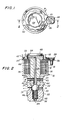
- Figure 1 is a top plan view of an improved solenoid valve according to the present invention;
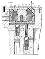
- Figure 2 is a cross-sectional view of the solenoid valve taken along line 2-2 of Figure 1;
- Figure 3A-3D are a series of fragmentary cross-sectional views showing the initial position, two intermediate positions, and the final position of the armature of the solenoid according to the present invention;
- Figure 4 is a graph showing the improved performance of the solenoid of the present invention in comparison with the prior art solenoid;
- Figure 5 is a top plan view of a modified form of a solenoid valve according to the present invention;
- Figure 6 is a cross-sectional view of the modified solenoid valve taken along lines 6-6 of Figure 5;
- Figure 7 is a cross-sectional view of a further modification of the solenoid valve according to the present invention;
- Figure 8 is a modification of the solenoid valve shown in Figure 2 wherein the actuating pin is offset from the axis of the solenoid; and
- Figure 9 is a further modification of the solenoid valve shown in Figure 2 wherein the armature member is divided.
- Referring first to Figures 1 and 2, the solenoid valve body is indicated generally by the
numeral 10 and comprises anupper solenoid portion 12 and alower valve portion 14. Thevalve body 10 is symmetrical about its axis and is made from a magnetic material so as to be capable of functioning as part of . a magnetic circuit. Preferably, thebody 10 is formed with five concentric and communicating bores. At the top, the largest bore is thesolenoid bore 16 which is adapted to receive thesolenoid coil 18. A second andsmaller sleeve bore 20 is positioned concentrically between thesolenoid bore 16 and a ball valve bore 22. The fourth and still smaller spring bore 24 communicates between the ball valve bore 22 and arelief aperture 26. - The
valve portion 14 of thebody 10 hasthreads 28 formed exteriorly thereon to facilitate the attachment of the solenoid valve to a machine (not shown) or other device with which the valve may be used. It will be understood that appropriate gaskets, washers or 0-ring seals (not shown) may also be employed, Anannular groove 29 is formed on the outer surface of thevalve portion 14 and adiametral passageway 30 communicates between theannular groove 29 and the ball valve bore 22. A secondannular groove 32 is formed in thevalve portion 14 of thesolenoid body 10 and communicates through a seconddiametral passageway 34 with thesleeve bore 20. Theannular groove 32 may, for example, communicate with a source of fluid, such as oil, under pressure while theannular groove 29 communicates with a device requiring a supply of pressurized fluid. - A
sleeve 36 made from a magnetic material is press fitted into thesleeve bore 20, or otherwise closely fitted to thesleeve bore 20, and extends upwardly to a point near the top of thesolenoid body 10. Thesleeve 36 is provided with anaxial bore 38 which contains an enlargedregion 40 at the the lower end thereof. Anannular groove 42 is formed on the outside surface of thesleeve 36 so as to register with thediametral passageway 34 and adiametral passageway 44 communicates between theannular groove 42 and the enlargedregion 40 of theaxial bore 38. - A
ball valve 46 is located in the ball valve bore 22 and biased by aspring 48 against aseat 50 formed in the lower end of thesleeve 36 by the enlargedregion 40 of theaxial bore 38. Thespring 48 is seated in thespring bore 24. - The
solenoid coil 18 may be sealed into.thesolenoid portion 12 of thesolenoid body 10 byappropriate potting material 52. Oneterminal 54 of thesolenoid coil 18 may be connected electrically to thesolenoid portion 12 of thesolenoid body 10 which, in this event, would be appropriately grounded, while theother terminal 56 of thesolenoid coil 18 carries ascrew 58 to connect thesolenoid coil 18 to an appropriate electrical circuit (not shown). Of course, external terminals for both ends of the solenoid coil may also be provided. - An
annular cap 60 made from a magnetic material is affixed to thesolenoid portion 12 of thebody 10, for example, by crimping athin wall portion 62 of thebody 10 over the rim of thecap 60. Thethin wall portion 62 thus provides a magnetic circuit means to interconnect theannular cap 60 and thesolenoid portion 12 of thebody 10 which, in turn, is in magnetic connection with thesleeve 36. The upper portion of thecap 60 is preferably star shaped and is adapted to be engaged by a standard 12-point socket wrench to facilitate tightening of thesolenoid body 10 into a threaded seat (not shown). Of course, thecap 60 may be designed to be engaged by other types of spanner wrenches or equivalent tightening means may be formed on the exterior surface of thesolenoid portion 12 of thebody 10. Preferably aninsert 64 made from a non-magnetic material is fitted into theannular cap 60. While theinsert 64 is illustrated in Figure 2 as having a large central orifice, it may be desirable to reduce the size of the orifice to inhibit the introduction of foreign material into the armature chamber or to eliminate the orifice if no venting is desired. Adrive pin 66, preferably formed from a non-magnetic material, is mounted for reciprocating movement within the axial bore 38 of thesleeve 36 and is of such length as to contact theball valve 46 at its lower end and anarmature member 68 at its upper end. When theball valve 46 is in contact with itsseat 50, thedrive pin 66 pushes thearmature member 68 upwardly and closely adjacent to the lower surface of theinsert 64. It will be understood that thedrive pin 66 is not affixed to either theball valve 46 or thearmature member 68, - The
armature member 68 is made from a magnetic material and is slightly smaller than the inside dimension of theannular cap 60 which defines an armature chamber. As shown in Figures 1 and 2, thearmature member 68 is, preferably, disc shaped and loosely located in the armature chamber of theannular cap 60. It will thus be apparent that thearmature member 68 is freely moveable, i.e., relatively unrestrained, and may have components of motion with respect to thedrive pin 66 which comprise translation or rotation or both. In order to accomplish this motion, the maximum dimension of the armature must be less than the inside dimension of the armature chamber, the precise amount of the lateral clearance not being critical. - Referring particularly to Figure 2, the magnetic circuit includes the
solenoid portion 12 of thebody 10, thethin wall portion 62 of thebody 10, thesleeve 36, thearmature member 68 and theannular cap 60. In this circuit, two air gaps are initially present, a lateral one between the armature member and the inside wall of theannular cap 60 and an axial gap between the armature and the upper end of the sleeve. Because there is relatively little resistance to lateral movement of the armature, immediately upon passage of a current through thecoil 18, the resulting magnetic field will exert a force on thearmature member 68 which will cause it to slide relative to thedrive pin 66 until contact is made between thearmature member 68 and a point on the internal wall of thecap 60, Of course, thearmature member 68 may fortuitously already be in contact with the internal peripheral wall of thecap 60. In either event, the practical effect is that the magnetic circuit effectively eliminates one of the air gaps leaving thereby only a single air gap -- the gap between thearmature member 68 and thesleeve 36, - Reference is now made to Figures 3A-3D which show, schematically, the movement of the
armature member 68 and drivepin 66 when electrical current is caused to flow in thecoil 18, Figure 3A represents the general condition of thearmature member 68 when no current is flowing in thecoil 18. Under this condition, thespring 48 will urge theball valve 46 against itsseat 50 and push thedrive pin 66 upwardly. If pressurized hydraulic fluid is present above theball valve 46 in the regions identified by thenumerals drive pin 66 forcing it upwardly until thedrive pin 66 holds thearmature member 68 against theinsert 64 as suggested by thearrow 70 in figure 3A. As soon as current begins to flow in thecoil 18, a magnetic field will be established which will exert a force on thelightweight armature member 68, Since the annular gap between thearmature member 68 and thecap 60 will, in general, not be uniform, the armature member will first move in the direction where the smallest gap exists since, at this point, the force across the gap is at a maximum. This initial motion is indicated by thearrow 72 in Figure 3B and the remaining air gap is indicated by thedimension 74 in Figure 3B, - As shown in Figure 3C, the force across the air gap between the
sleeve 36 and thearmature member 68 tends to cause the armature member to pivot about the point A so as to provide a lever action which will begin to force thedrive pin 66 to move in a downwardly direction, as indicated by the arrow 76, thedimension 78. Theair gap 74 between thearmature member 68 and the sleeve will become uneven with the force tending to pivot the armature member increasing. It will be appreciated that the lever action referred to above will increase the force on thepin 66 which tends to overcome the force ofspring 48 to open theball valve 46. - Ultimately, the
gap 74 will be substantially closed as shown in Figure 3D as thedrive pin 66 reaches the limit of its travel. At this point, the gap may be on the order of 0.010 inch. - It will be appreciated that the initial movement of the
armature member 68 which eliminates the gap between the armature member and thecap 60 occurs under almost frictionless conditions and therefore is accomplished very quickly. Thus, the actual amount or dimension of this first gap is of no great significance. The pivotal motion of the armature member begins immediately thereafter whenonly gap 74 remains. As the clearances in the mechanical system must first be taken up, the ensuing pivoted motion produces first an impact effect and then a lever action which produces a mechanical advantage in driving thepin 66 downwardly. The mechanical advantage is developed in part because the resultant force is further from the pivot point A than is the axis of thedrive pin 66. The location of the resultant force is dictated by the increased flux density associated with the narrower portion of theair gap 74, - The operation of the solenoid according to the present invention in comparison with typical prior solenoids is shown in Figure 4. In the tests represented by Figure 4, identical solenoid coils were utilized. The coil data is shown in Table 1 below:

- The curves of Figure 4 show the force developed by each solenoid as a function of the
air gap 74. As the solenoid coils used in the test were identical, the improved performance as measured, for example, by the vertical distances C, C' is necessarily due to the novel design of applicant's armature which enables the solenoid to function in a new and improved manner. - It has been noted above that the initial sliding motion of the armature member occurs under substantially frictionless conditions and the initial pivoting action also requires very little force as this motion occurs while the clearance in the system is being taken up. Thus, while the air gap is at its maximum, the required operating forces are at a minimum so that the solenoid according to the present invention is a rapid acting device. These characteristics are of particular significance. First, since the initial motion requires little force, the tolerance on the dimensions of the armature member and pin and the free travel of the armature member and pin are not critical and therefore the cost of the solenoid may be minimized. Second, the high speed characteristic of the solenoid according to the present invention fits it for use in devices such as a comprsssion relief engine brake where fast and reliable solenoid operation is required.
- It is to be understood that a number of variations are possible within the scope of the invention, Thus, while it is convenient to use an axially symmetric solenoid with a round armature in the form of a disc and an axial pin, it is possible to make the armature member or coil or both in an elliptical or rectangular shape, and the drive pin may be offset from the solenoid axis. Indeed, if it is desired to increase the solenoid force at the expense of reduced travel, the
pin 66 may be offset from the axis as shown in Figure 8, Parts common to Figures 2 and 8 are shown by the same designators while modified parts are indicated by a prime. In this instance, only the sleeve member 36' need be modified by providing a bore 38' therein which is offset from the axis of the sleeve by the desired amount, With this modification, the longer overhanging portion of thearmature member 68; i.e., that part to the left ofpin 66 as viewed in Figure 8, will be drawn towards thecoil 18 first and the shorter portion of thearmature member 68 is adjacent the pivot point A. Because thepin 66 is located closer to the pivot point A, the mechanical advantage of the armature and pin linkage is increased. - In addition to modifying the shape of the armature member and solenoid, it is possible to split the armature member, for example, along an axis of symmetry. This further modification is shown in Figure 9 where, as in Figure 8, parts common to Figures 2 and 9 are shown by the same designators while modified parts are indicated by a prime. In this modification, only the armature member 68' need be modified by dividing it, for example, along an axis of symmetry. In this form of the invention, the initial motion of the divided armature 68' will be towards the internal periphery of the
annular cap 60 so as to establish pivot points A' and A " . Thereafter, the divided armature 68' will act against the upper end of thepin 66 to drive it downwardly, - Depending on the geometry and tolerances in the system, this type of modification may further decrease the initial air gap and, consequently, decrease the time within which the solenoid begins to act.
- It will be understood that the improved, compact solenoid of the present invention can be further modified to operate various associated mechanisms, While it has been illustrated in conjunction with a ball valve in Figure 2, the solenoid may be used with other types of hydraulic or pneumatic devices or to operate electrical switching mechanisms or microswitches. Examples of such further modifications are shown in Figures 5 through 7.
- Reference is now made to Figures 5 and 6 which illustrate a modification of the present invention to provide a combination of a solenoid and valve where the solenoid and valve is integral with the equipment with which it is employed.
- The
machine body 80 formed from a magnetic material has formed therein abore 82 to accommodate thesolenoid valve assembly 84. A somewhat smallerconcentric bore 86 is also formed in themachine body 80 to receive, preferably, a pad or disc ofnon-magnetic material 88. The remainder of thebore 86 functions as an armature chamber and receives the relatively unrestrained armature member 90. It will be appreciated that the non-magnetic pad ordisc 88 may, alternatively be affixed to the armature member 90, if desired. While it is preferred to provide a disc ofnon-magnetic material 88, such a disc may be replaced by an air gap or may be omitted entirely. The armature member 90 is shown in solid lines in Figure 6 in its unenergized condition while the phantom lines indicate the fully energized position. As shown in Figure 6 the armature member 90 fits loosely or freely in thebore 86 so as to provide a small annular gap between the armature member 90 and thebore 86. It will be appreciated that themachine body 80 forms a portion of the magnetic circuit required for the action of thesolenoid assembly 84. This requires that themachine body 80 be formed from a magnetic material. It will be understood that if themachine body 80 is formed from a non-magnetic material, such as aluminum, for example, an insert made from a magnetic material, such as iron, could be placed in themachine body 80 in the region of the solenoid assembly to meet the requirements of the magnetic circuit. - The
solenoid assembly 84 comprises a cylindricalsolenoid body portion 92 having acircumferential shoulder 94 to accommodate an 0-ring seal 96 which provides a seal between thesolenoid body 92 and thebore 82. Asleeve 98 is press fitted or otherwise joined to thesolenoid body 92. Thesleeve 98 is provided with anaxial bore 100, the upper end of which may be tapped to form a connection for a fluid line (not shown). Avalve seat 102 may be formed on the opposite or inner end of thesleeve 98. Aplate 104 is fitted on thesolenoid body 92 in magnetic contact with thesleeve 98 and is fastened to themachine body 80 by a plurality offasteners 106 so as to complete the magnetic circuit between thesleeve member 98 and themachine body 80 and function as a magnetic circuit means. - A
solenoid coil 108 is placed in thesolenoid body 92 and sealed in place byappropriate potting material 110. Oneterminal 112 of thesolenoid coil 108 extends upwardly through thepotting material 110 while theother terminal 114 may be grounded to theplate 104. Apassageway 116 in themachine body 80 communicates between thebore 82 and a portion of the machine (not shown) requiring an intermittent supply of fluid. - As shown in Figures 5 and 6,the solenoid valve of the present-invention is normally open in the unenergized state and fluid entering the
bore 100 may pass freely through thebore 100, thebore 82 and thence through thepassage way 116. When electrical current is passed through the solenoid 108 a magnetic field is created in the magnetic circuit comprising thesleeve 98, theplate 104, themachine body 80 and the armature 90. Initially, as shown in Figure 6, the magnetic circuit contains two air gaps: (Jl the annular gap between the armature member 90 and thebore 86 and (2) the gap between the armature member 90 and theseat 102 on thesleeve 98. However, the first gap is closed quickly as the armature member 90 slides on thepad 88 until it contacts thebore 86, for example, at point B. Thereafter, the armature member 90 pivots about the point B until the armature member strikes thevalve seat 102. Finally, the armature member 90 will come to rest making surface contact with thevalve seat 102 to close thebore 100 and prevent further flow of fluid throughbore 100, It will be understood that at least the central portion of the upper surface of the armature member 90 and the bottom portion of thesleeve 98 comprising thevalve seat 102 must be ground flat so as to provide a fluid-tight closure. If desired, thevalve seat 102 may be formed separately from thesleeve 98 and pressed or otherwise attached to thesleeve 98. - Normally the pressure of the fluid within the
bore 100 and the weight of the armature member 90 will be sufficient to insure opening of the solenoid valve when the electrical current in the solenoid coil is turned off. However, a light spring, preferably formed from a non-magnetic material may be installed to urge the armature member 90 away from thevalve seat 102. Such an arrangement may also be used if it is desired to operate the solenoid valve in an inverted position. - A further modification is shown in Figure 7 wherein the solenoid of the present invention is used to operate a plurality of valves. In this modification, the figure 118 designates a machine body made from a magnetic material such as iron or steel having formed therein a
bore 120 which accommodates thesolenoid assembly 122. Apassageway 124 communicates between a source of fluid (not shown) and thebore 120.Bores machine body 118 and also communicate with thebore 120.Bore 130 communicates between thebore 126 and a first part of themachine body 118 requiring an intermittent supply of fluid whilebore 132 communicates betweenbore 128 and a second part of themachine body 118 requiring an intermittent supply of fluid. - A
ball valve 134 is positioned in thebore 126 and biased against aseat 136 by alight spring 138 seated inplug 140 threaded into thebore 126. Theball valve 134 is shown in its closed position in solid lines while its open position is indicated by phantom lines. - A
second ball valve 142 is positioned in thebore 128 and biased against aseat 144 by alight spring 146 seated in aplug 148 threaded into thebore 128. Again, the ball valve .142 is shown in its closed position by solid lines while the open position is indicated by phantom lines. Apin 150 is positioned in thebore 128 between theball valve 142 and apad 152 on thearmature member 154 which is loosely or freely positioned within thebore 120, Asecond pad 156 may be formed on thearmature member 154 to contact theball valve 136. Thepads armature member 154 is shown in its energized position by solid lines and in its unenergized position in phantom lines. - The
solenoid assembly 122 comprises acylindrical body portion 158 having acircumferential shoulder 160 adapted to carry an 0-ring seal 162 which seals thesolenoid body 158 is affixed to aplate 164 formed from a magnetic material which plate is fastened to themachine body 118 by a plurality ofscrews 166. A core orsleeve 168 formed from a magnetic material is press fitted or otherwise fastened to thebody 158 and theplate 164 so as to provide good magnetic contact with theplate 164. Anaxial bore 170 is formed in thesleeve 168 to locate a relatively heavy compression spring 172. Compression spring 172 is designed with a higher spring rate than the sum of the spring rates ofsprings armature member 154 will normally be positioned as shown in the phantom lines and theball valves - A
solenoid coil 174 is located in thebody 158 and sealed therein byappropriate potting material 176. Oneterminal 178 of thesolenoid coil 174 may conveniently be grounded to theplate 164 while theother terminal 180 extends upwardly through thepotting material 176. - In operation, upon passage of an electric current through the
solenoid coil 174, a magnetic field will be established in the magnetic circuit which comprises themachine body 118, theplate 164, thesleeve 168 and thearmature 154. Thearmature member 154 will first slide laterally to close the annular gap between it and the inner peripheral edge of thebore 120. Thereafter, thearmature member 154 will pivot about the point of contact as previously described and finally come to rest against the lower side of thesolenoid body 158, It will be understood that when thesolenoid 174 is energized thearmature 154 will be in the position shown by the solid lines in Figure 7 and bothball valves conduit 124 is sufficiently high to overcome the force of thesprings solenoid 174 is deenergized, high pressure fluid may flow from theconduits ball valves conduit 124 in a reverse direction until the pressure in the system is substantially equalized, - While
separate pads armature member 154. If thearmature member 154 is disc shaped, it may be desirable to combine thepads - In Figure 7,
ball valve 142 is separated from thearmature member 154 by thepin 150 while no similar pin is used in conjunction withball valve 134. It will be understood that both valves may utilize either construction as may be desired. Moreover, more than two valves may be controlled by thesolenoid assembly 122 provided that the spring rate of spring 172 exceeds the combined rate of the ball valve springs. Finally, while ball valves have been described and illustrated, other types of valves such as poppet valves, leaf valves or sliding or spool valves could be substituted for the ball valves. - The embodiment of the invention shown in Figure 7 is particularly desirable for use in the operation of a compression relief engine brake of the type disclosed in U.S. patent 3,220,392, for example, where both a solenoid and a control valve are required and a high-speed but compact and reliable system is desired.
- The terms and expressions which have been employed are used as terms of description and not of limitation and there is no intention in the use of such terms and expressions of excluding any equivalents of the features shown and described or portions thereof, but it is recognized that various modifications are possible within the scope of the invention claimed,
Claims (14)
Priority Applications (3)
| Application Number | Priority Date | Filing Date | Title |
|---|---|---|---|
| AT80303981T ATE13104T1 (en) | 1980-11-06 | 1980-11-06 | SOLENOID. |
| DE8080303981T DE3070590D1 (en) | 1980-11-06 | 1980-11-06 | Improved solenoid |
| EP80303981A EP0051702B1 (en) | 1980-11-06 | 1980-11-06 | Improved solenoid |
Applications Claiming Priority (1)
| Application Number | Priority Date | Filing Date | Title |
|---|---|---|---|
| EP80303981A EP0051702B1 (en) | 1980-11-06 | 1980-11-06 | Improved solenoid |
Publications (2)
| Publication Number | Publication Date |
|---|---|
| EP0051702A1 true EP0051702A1 (en) | 1982-05-19 |
| EP0051702B1 EP0051702B1 (en) | 1985-05-02 |
Family
ID=8187294
Family Applications (1)
| Application Number | Title | Priority Date | Filing Date |
|---|---|---|---|
| EP80303981A Expired EP0051702B1 (en) | 1980-11-06 | 1980-11-06 | Improved solenoid |
Country Status (3)
| Country | Link |
|---|---|
| EP (1) | EP0051702B1 (en) |
| AT (1) | ATE13104T1 (en) |
| DE (1) | DE3070590D1 (en) |
Cited By (1)
| Publication number | Priority date | Publication date | Assignee | Title |
|---|---|---|---|---|
| DE3912042A1 (en) * | 1988-04-12 | 1990-01-11 | Scholz Joachim | Electromagnet |
Citations (8)
| Publication number | Priority date | Publication date | Assignee | Title |
|---|---|---|---|---|
| GB564351A (en) * | 1941-08-21 | 1944-09-25 | Landis & Gyr Sa | Improved electro-magnetic apparatus with tilting armatures, more especially tilting relays |
| DE1173582B (en) * | 1963-04-18 | 1964-07-09 | Licentia Gmbh | Magnetic release system for switchgear |
| GB998096A (en) * | 1961-02-06 | 1965-07-14 | Robert Moser | A highly sensitive electromagnet and armature unit |
| US3327264A (en) * | 1965-04-23 | 1967-06-20 | Keith S Rodaway | Alternating current solenoid construction |
| DE1278609B (en) * | 1963-08-09 | 1968-09-26 | Teldix Luftfahrt Ausruestung | Electromagnet with armature mounted on rolling bodies |
| DE1464526A1 (en) * | 1963-11-09 | 1969-04-24 | Concordia Maschinen U Elek Zit | Electromagnetically operated valve |
| US3677826A (en) * | 1970-01-04 | 1972-07-18 | Rene Pointout | Three-way solenoid-operated valves |
| US3880476A (en) * | 1972-12-20 | 1975-04-29 | Itt | Electromagnetic valve |
-
1980
- 1980-11-06 DE DE8080303981T patent/DE3070590D1/en not_active Expired
- 1980-11-06 AT AT80303981T patent/ATE13104T1/en not_active IP Right Cessation
- 1980-11-06 EP EP80303981A patent/EP0051702B1/en not_active Expired
Patent Citations (8)
| Publication number | Priority date | Publication date | Assignee | Title |
|---|---|---|---|---|
| GB564351A (en) * | 1941-08-21 | 1944-09-25 | Landis & Gyr Sa | Improved electro-magnetic apparatus with tilting armatures, more especially tilting relays |
| GB998096A (en) * | 1961-02-06 | 1965-07-14 | Robert Moser | A highly sensitive electromagnet and armature unit |
| DE1173582B (en) * | 1963-04-18 | 1964-07-09 | Licentia Gmbh | Magnetic release system for switchgear |
| DE1278609B (en) * | 1963-08-09 | 1968-09-26 | Teldix Luftfahrt Ausruestung | Electromagnet with armature mounted on rolling bodies |
| DE1464526A1 (en) * | 1963-11-09 | 1969-04-24 | Concordia Maschinen U Elek Zit | Electromagnetically operated valve |
| US3327264A (en) * | 1965-04-23 | 1967-06-20 | Keith S Rodaway | Alternating current solenoid construction |
| US3677826A (en) * | 1970-01-04 | 1972-07-18 | Rene Pointout | Three-way solenoid-operated valves |
| US3880476A (en) * | 1972-12-20 | 1975-04-29 | Itt | Electromagnetic valve |
Cited By (1)
| Publication number | Priority date | Publication date | Assignee | Title |
|---|---|---|---|---|
| DE3912042A1 (en) * | 1988-04-12 | 1990-01-11 | Scholz Joachim | Electromagnet |
Also Published As
| Publication number | Publication date |
|---|---|
| EP0051702B1 (en) | 1985-05-02 |
| DE3070590D1 (en) | 1985-06-05 |
| ATE13104T1 (en) | 1985-05-15 |
Similar Documents
| Publication | Publication Date | Title |
|---|---|---|
| US4251051A (en) | Solenoid structure having a relatively unrestrained generally flat armature member | |
| US3707992A (en) | Electromagnetic valve assembly | |
| US3653630A (en) | Solenoid valve with plural springs | |
| US5513832A (en) | Variable force solenoid valve | |
| US6065495A (en) | Two-position, three-way solenoid-actuated valve | |
| US5205323A (en) | Valve and operator therefor | |
| US4524947A (en) | Proportional solenoid valve | |
| US4338966A (en) | Direct solenoid operated directional control valve | |
| US2968464A (en) | Pressure operated valve with magnetically actuated pilot | |
| JPH0559307B2 (en) | ||
| US5791630A (en) | Flow control valve | |
| US4174824A (en) | Pressure operated pilot control shut-off valve | |
| CA2194116A1 (en) | Proportional variable force solenoid control valve | |
| JP2622370B2 (en) | Flow direction control valve | |
| US6305664B1 (en) | Proportional variable bleed solenoid valve with single adjustment pressure calibration and including poppet valve seal ball | |
| CA2469563C (en) | Pilot operated pneumatic valve | |
| US6068237A (en) | Proportional variable bleed solenoid valve with single adjustment pressure calibration | |
| US5311162A (en) | Solenoid device | |
| EP0795706A1 (en) | Universal on/off solenoid valve assembly | |
| JP4312390B2 (en) | Proportional pressure regulating valve | |
| GB2124034A (en) | Solenoid valve | |
| US4293002A (en) | Electrically operated fluid control device | |
| US3656076A (en) | Time delay electromagnetic device | |
| EP0051702B1 (en) | Improved solenoid | |
| US4694270A (en) | Electromagnetic proportional actuator |
Legal Events
| Date | Code | Title | Description |
|---|---|---|---|
| PUAI | Public reference made under article 153(3) epc to a published international application that has entered the european phase |
Free format text: ORIGINAL CODE: 0009012 |
|
| AK | Designated contracting states |
Designated state(s): AT BE CH DE FR GB IT LU NL SE |
|
| 17P | Request for examination filed |
Effective date: 19820615 |
|
| ITF | It: translation for a ep patent filed |
Owner name: INTERPATENT ST.TECN. BREV. |
|
| GRAA | (expected) grant |
Free format text: ORIGINAL CODE: 0009210 |
|
| RAP1 | Party data changed (applicant data changed or rights of an application transferred) |
Owner name: THE JACOBS MANUFACTURING COMPANY |
|
| AK | Designated contracting states |
Designated state(s): AT BE CH DE FR GB IT LI LU NL SE |
|
| REF | Corresponds to: |
Ref document number: 13104 Country of ref document: AT Date of ref document: 19850515 Kind code of ref document: T |
|
| REF | Corresponds to: |
Ref document number: 3070590 Country of ref document: DE Date of ref document: 19850605 |
|
| ET | Fr: translation filed | ||
| PG25 | Lapsed in a contracting state [announced via postgrant information from national office to epo] |
Ref country code: LU Free format text: LAPSE BECAUSE OF NON-PAYMENT OF DUE FEES Effective date: 19851130 |
|
| PLBE | No opposition filed within time limit |
Free format text: ORIGINAL CODE: 0009261 |
|
| STAA | Information on the status of an ep patent application or granted ep patent |
Free format text: STATUS: NO OPPOSITION FILED WITHIN TIME LIMIT |
|
| 26N | No opposition filed | ||
| PGFP | Annual fee paid to national office [announced via postgrant information from national office to epo] |
Ref country code: AT Payment date: 19861024 Year of fee payment: 7 |
|
| PGFP | Annual fee paid to national office [announced via postgrant information from national office to epo] |
Ref country code: NL Payment date: 19871130 Year of fee payment: 8 |
|
| PG25 | Lapsed in a contracting state [announced via postgrant information from national office to epo] |
Ref country code: GB Effective date: 19881106 Ref country code: AT Effective date: 19881106 |
|
| PG25 | Lapsed in a contracting state [announced via postgrant information from national office to epo] |
Ref country code: SE Effective date: 19881107 |
|
| PG25 | Lapsed in a contracting state [announced via postgrant information from national office to epo] |
Ref country code: LI Effective date: 19881130 Ref country code: CH Effective date: 19881130 Ref country code: BE Effective date: 19881130 |
|
| BERE | Be: lapsed |
Owner name: THE JACOBS MANUFACTURING COMPANY Effective date: 19881130 |
|
| PG25 | Lapsed in a contracting state [announced via postgrant information from national office to epo] |
Ref country code: NL Effective date: 19890601 |
|
| NLV4 | Nl: lapsed or anulled due to non-payment of the annual fee | ||
| GBPC | Gb: european patent ceased through non-payment of renewal fee | ||
| PG25 | Lapsed in a contracting state [announced via postgrant information from national office to epo] |
Ref country code: FR Free format text: LAPSE BECAUSE OF NON-PAYMENT OF DUE FEES Effective date: 19890731 |
|
| REG | Reference to a national code |
Ref country code: CH Ref legal event code: PL |
|
| PG25 | Lapsed in a contracting state [announced via postgrant information from national office to epo] |
Ref country code: DE Effective date: 19890801 |
|
| REG | Reference to a national code |
Ref country code: FR Ref legal event code: ST |
|
| EUG | Se: european patent has lapsed |
Ref document number: 80303981.7 Effective date: 19890726 |