EP0052725A1 - Method of reducing the print element changes in a text processing system - Google Patents
Method of reducing the print element changes in a text processing system Download PDFInfo
- Publication number
- EP0052725A1 EP0052725A1 EP81107926A EP81107926A EP0052725A1 EP 0052725 A1 EP0052725 A1 EP 0052725A1 EP 81107926 A EP81107926 A EP 81107926A EP 81107926 A EP81107926 A EP 81107926A EP 0052725 A1 EP0052725 A1 EP 0052725A1
- Authority
- EP
- European Patent Office
- Prior art keywords
- character
- code
- print element
- printer
- logic sequence
- Prior art date
- Legal status (The legal status is an assumption and is not a legal conclusion. Google has not performed a legal analysis and makes no representation as to the accuracy of the status listed.)
- Granted
Links
Images


Classifications
-
- B—PERFORMING OPERATIONS; TRANSPORTING
- B41—PRINTING; LINING MACHINES; TYPEWRITERS; STAMPS
- B41J—TYPEWRITERS; SELECTIVE PRINTING MECHANISMS, i.e. MECHANISMS PRINTING OTHERWISE THAN FROM A FORME; CORRECTION OF TYPOGRAPHICAL ERRORS
- B41J25/00—Actions or mechanisms not otherwise provided for
- B41J25/24—Case-shift mechanisms; Fount-change arrangements
-
- G—PHYSICS
- G06—COMPUTING; CALCULATING OR COUNTING
- G06F—ELECTRIC DIGITAL DATA PROCESSING
- G06F40/00—Handling natural language data
- G06F40/10—Text processing
- G06F40/103—Formatting, i.e. changing of presentation of documents
- G06F40/109—Font handling; Temporal or kinetic typography
Definitions
- This invention generally relates to a method of reducing print element changes in a text processing system and more specifically, relates to expanding the usefulness of print elements in order to reduce print element change requirements and increase throughput.
- each of the characters and/or graphics included on a print element exist at a particular location on the element.
- the locations are the same on a wide variety .of elements.
- a lower case "a” will exist at the same location on many of the print elements available for a particular system.
- a change in keyboard coding presents no problem for this character as long as the character exists on the print element being used.
- US-A 4,205,922 addresses the problems of stored print element change requirements not corresponding to current printer requirements. That is, when text is stored sequentially, but printed out non-sequentially, a stored print element change requirement may not, in fact, require a change in elements.
- the disclosed system is structured to alert the operator only when changes are actually necessary.
- the above described art is relevant to varying degrees, but falls short of either anticipating or rendering the instant invention obvious. More specifically, the instant invention presents an advance over the prior art in that sequentially called for print element changes are actually required and signalled only when the print element in use does not contain the next character to be printed and the next character to be printed cannot be constructed from the characters existing on the print element in use.
- the characters making up the various keyboards available to the system are mapped in a minimum number of keyboard code maps. Existing in various of the maps are characters which are identically coded. In other instances, different coding represents different characters in different maps.
- the system will select an appropriate keyboard code map to distinguish coding during input keying. Both selections are stored in a buffer such that a keyboard code map identification code and a keyboard indentification code properly identify following text codes. Assuming that at a particular point in time, printing is from the buffer and the print element in use matches the last read keyboard identification code. Each character code read is reordered to determinate whether it falls within either an invariant, variant, or composite character category. Regardless, reading causes a printing of the corresponding character.
- the category can become important. If invariant, reordering causes a printing as before. If the character falls within a variant category and exists on the element, a translation operation is necessary. This is to correct for the code read not matching the disired character position on the element. If the character is not available on the element and the character is not a composite character, a change requirement is signalled. If the character falls within a composite category, and the characters required to construct the composite character are available, category determinations are made to determine whether printing will occur from reordering and/or a translation operation. Regardless, printing is caused to occur. If the character cannot be constructed due to the absence of a required character on the print element, a change requirement is signalled.
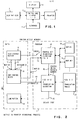
- Fig. 1 In this figure is shown a simplified block diagram illustration of a basic text processing system.
- the system includes a keyboard 1 having an alpha/ numeric section and an outboard section.
- the alpha/numeric section includes standard keys and bars for characters, numbers, symbols, spaces, carrier returns, case shifts, etc.
- the outboard section includes keys for cursor control, power on/off, etc.
- the particular arrangement and inclusion of keys in either section is irrelevant. Of importance is that there are sufficient keys available to 1) support use of a plurality of print elements, and 2) cause a system change upon the keying of a change in keyboard coding.
- Keyboard 1 is connected to a control and storage unit 2.
- control and storage unit 2 are a storage device including a text storage buffer, and a processor for controlling reading and writing of data out of, and into, the text storage buffer. Further details of the storage of unit 2 will be set forth later herein when reference is made to Fig. 2. Further details of the processor will be set forth in the following explanation of Fig. 3.
- the processor in Fig. 3 is denoted by reference 60.
- Processor 60 also controls the output of data to a printer 3, a CRT display 4, and a floppy disk reader/recorder 5. The actual control of printer 3, display 4, and reader/recorder 5 forms not part of this invention. Therefore, further discussion is not considered warranted.
- Processor 60 is under the control of programs read off of a floppy disk into the storage device of control and storage unit 2. As far as this invention is concerned, it is to be assumed that the programs have already been read, and stored in unit 2.
- Fig. 2 shows a random access memory divided into a data section 6 and a processor section 7.
- Data section 6 includes a text storage buffer 8, a unit control block 9, and a line buffer 10.
- a text storage buffer 8 includes a text storage buffer 8 and a unit control block 9, and a line buffer 10.
- a line buffer 10 For purposes of the following description, it is to be assumed that an operator has keyed and caused the storing of text and appropriate keyboard coding in text storage buffer 8. Also, it is to be assumed that all processor control programming has been stored in section 7, and that the processor will ultimately cause the characters stored in line buffer 10 to be printed. Characters stored in line buffer 10 are to be ultimately printed by printer 3 in Fig. 1 with a proper print element.
- processor 60 sequentially reads each character and other code from buffer 8 along line 21.
- a code was stored for a keyed keyboard identification and following keyed characters. Based on the keyed keyboard identification, a keyboard code map was chosen and an identifiaction code was stored therefore.
- outputs are applied along lines 12 and 11, respectively, to unit control block 9.
- processor 60 causes a reordering operation under the control of a program denoted by block 15. This reordering will be further described when reference is made to Fig. 4.
- Control block 9 can simply be a storage device which is sampled on a needed basis. Following a reordering operation a reorder number is applied along line 16 for any needed translation operation by processor 60 under the control of a program denoted by block 17.
- the translation will be further described when reference is made to Figs. 8-12.
- a translation operation is meant to include matching a character on a print element in use with the character stored in buffer 8. A number of situations and circumstances arise which require a translation operation. One is that the coding required to drive the printer in use differs from the coding in buffer 8. Another is that, under the same situation as the first, keyboard coding for the characters in buffer 8 does not match the print element in use.
- code maps such as 18, 19, etc., which are set out later herein as tables V, VI, and VII are indexed.
- Table structure utilized during the translation operation and is represented by block 22, set out in Figs. 5-7. These figures will be described in greater detail later herein.
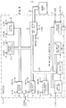
- Fig. 3 shows the details of processor 60 which is capable of performing the operations of this invention under program control.
- processor 60 includes an INTEL 8086 Microcomputer chip.
- Typical logic hardware elements forming processor 60 include a control logic unit 25 which responds to instructions from the random access memory of Fig. 2 applied along bus 28.
- the control logic 25 is also in the data stream identified by the data and address bus 26 interconnected to various other logic units of processor 60.
- control logic unit 25 In response to instructions from section 7, control logic unit 25 generates control signals to other logic elements of processor 60. These control signals are interconnected to the various elements by means of a control line 29 which is illustrated directly connected to an arithmetic logic unit 30 and identified as a "control" line 29 to other elements of processor 60. Synchronous operations of the control unit 25 with other logic elements of processor 60 is achieved by means of clock pulses input to processor 60 from an external clock source on bus 31. This bus is also shown interconnected to various other logic elements of processor 60. In addition, bus 31 is also shown interconnected to various other logic elements of processor 60. In addition, bus 31 is connected to reader/recorder 5, display 4, and the memory shown in Fig. 2.
- Data to be processed in processor 60 is input either through a bus control logic unit 32 or a program input/ output control unit 33.
- the bus control logic 32 connects to the random access memory of Fig. 2 and receives instructions for processing data input to input/output control 33.
- input/output control 33 receives data from keyboard 1 while bus control logic 32 receives instructions from the random access memory.
- different storage sections of the random access memory are identifiable for instruction storage and data storage.
- Device controls from processor 60 are output through program input/output control unit 33 over a data bus 27.
- Input data on the data bus 28 is passed internally through processor 60 on the bus 26 to control unit 25.
- Arithmetic logic unit 30 in response to a control signal on line 29 and in accordance with instructions received on memory bus 28, performs arithmetic computations which may be stored in temporary scratch registers 34.
- Various other transfers of data between the arithmetic logic unit 30 and other logic elements of processor 60 are, of course, possible. Such additional transfers may be to a status register 35, data pointer register 36 or a stack pointer register 37.
- Also in the data stream for these various logic elements by means of the bus 26 is a program counter 38.
- a particular operating sequence for processor 60 is determined by instructions on the memory bus 28 and input data on the bus 28, or bus 27 from keyboard 1. As an example, in response to received instructions, processor 60 transfers data stored in scratch registers 34 to one of registers 36, 37, or 35.
- processor 60 transfers data stored in scratch registers 34 to one of registers 36, 37, or 35.
- EBCDIC Extended Binary Coded Decimal Interchange Code
- X'40' is the first usable character, this value will be used as a basis in assigning reorder numbers to the other available characters.
- X'40' is represented in binary form as 01000000. In decimal or base 10,, X'40' is equal to 64.
- each of the characters are ordered and assigned a value according to their frequency of use. For example a small "a” is the most frequently used character and is assigned a decimal value of zero. This zero value is a reorder number which will be used as later described herein to either index a printer code for driving a golf ball printer or gate a code to an EBCDIC driven printer.
- the output coding of keyboard 1 will be EBCDIC
- storage in buffer 8 will be in EBCDIC
- the coding in line buffer 10 will vary accordingly to the printer being used.
- Certain printers can be driven directly with EBCDIC, while others such as single element (golf ball) IBM "Selectric" printers are driven with multibit codes which are transformed into tilt and rotate requirements.
- a printer which can be driven from EBCDIC is the daisy wheel 60 cps, IBM 5218 Printer. This invention is applicable to both types of printers in reducing the number of required print element changes.
- the categories are invariant, variant, and composite.
- the categories themselves vary according to the graphic set being used. For example, for the IBM "Selectric" printer 88 character graphic set, the invariant graphic reorder numbers range from 0-61. The variant graphic reorder numbers range from 62-154, and the composite reorder numbers range from 155-255. For the IBM 5218 printer 96 character graphic set, the invariant reorder numbers will range from 0-72, the variant graphic numbers will range from 73-154, and the composite reorder numbers will range from 155-255.
- the reorder number (in the first column of Table V) for the small "a" is zero. Identified is the invariant category, and as such the same character will exist in all of code maps 18, 19, etc., and on all the print elements. In the event a golf ball type printer is being utilized, requiring tilt and rotate information, the reorder number of zero is used to index into an invariant printer code table to obtain a code which can be used to meet tilt and rotate requirements in printing a small "a". As has been mentioned, each of the characters are categorized in terms of invariant, variant, and composite.
- a test represented by logic sequence 62 is made to determine whether the EBCDIC code is a graphic (character) code. If not, the graphic set reordering operation or sequence is terminated. The reason is that if the code is not a graphic, then it is a control to which the reordering operation is not applicable. If the code read out of the text storage buffer is a graphic code, then a subtraction operation is performed as indicated by logic sequence number 63. Following the subtraction operation, logic sequence 64 causes a conversion of the hexadecimal result to decimal for indexing into Table V. Following indexing into Table V to obtain a reorder number, a translation operation may be in order.
- the recorder number serves as a gating term for gating the code for the "a" read out of buffer to buffer 10. If the printer is not EBCDIC driven or the character is variant, a translation operation indicated by logic sequence 65 is performed.
- Translation logic sequence 65 is more fully described in detail in Figs. 8-12. Logic sequence 65 and the details set forth in Figs. 8-12 make up the algorithm of block 17 in Fig. 2. Before, the structure of the translation tables in block 22 of section 7 will be described. With reference to Figs. 5-7.
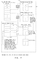
- Fig. 5 there is shown a storage table having stored therein, beginning at the top, the number of available invariant graphics. This number is dependent upon the printer in use.
- Fig. 6 Thereafter, code maps shown in Fig. 2 set out in Tables V, VI, and VII appear in the table, followed by a composite character table shown in more detail in Fig. 7.
- Fig. 7 Next is stored a length of the invariant printer table and the invariant printer table shown in Fig. 7, followed by the variant printer code table shown in Fig. 7.
- the portion of the table shown in Fig. 5 beginning with the composite character table and extending through the variant printer code table is included in block 22 of Fig. 2.
- Fig. 6 illustrates a print element table, an offset to which is referred to in Fig. 5.
- the table is made up, in order, of 1) the number of print element tables illustrated in Fig. 7, 2) the print element table total length, 3) a code map identifi ca - tion code which can represent any one of maps 1-3 (Tables V- VII ), 4) the number of graphic set identification codes, 5) a list of the graphic set identification codes available for use and supported by a particular print element, 6) the number of reorder numbers, i.e., how many variant graphics, and 7) a listing of the variant graphic reorder numbers. All of the print element table illustrated in Fig. 6 forms part of block 22 in Fig. 2.
- Fig. 7 In this figure is illustrated in the upper left hand corner a code map table 71 in which is stored any one of the contents of code maps 13. Depending upon which one of code maps 1-3 is stored in code map table 71, and the particular printer in use, pointers will be provided to invariant printer code table 72 and print element tables 73. With the exception of code map table 71, the remainder of Fig. 7 is included in block 22 of Fig. 2. Code map table 71 is included in either block 18, 19, etc., of Fig. 2. If the variant reorder number is found in the print element table, the translation algorithm is pointed to the variant printer code table 74.
- the translation algorithm is pointed to the composite character table 75 for the reorder numbers of the characters that can be used to construct the character.
- the reorder numbers from the composite character table point the translation algorithm to the print element table 73 or the print element table 73 and the variant printer code table 72.
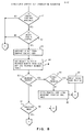
- Figs. 8-12 logic sequences 61-64 are indentical to those illustrated in Fig. 4. If a code map is not available and the character in EBCDIC code applied along line 21 is not a graphic, translation is not possible and the operation is terminated. This is illustrated by logic sequence 81 in Fig. 10.
- a test is performed by logic sequence 82 to determine if the character falls into an invariant graphic category. If there is a positive result of the test performed in logic sequence 82, a test is performed by logic sequence 83 to determine if the printer in use is an EBCDIC code driven printer. If so, the previously obtained reorder number is used as an ANDing condition for gating the EBCDIC code applied along line 21 to buffer 10 for ultimately driving the printer to print the character. This is indicated by logic sequence 84. If not, logic sequence 85 causes a printer code to be obtained from invariant printer code table 72 in Fig. 7. Upon obtaining the printer code from invariant printer code table 72, logic sequence 86 in Fig. 10 transmits the code to buffer 10.
- a test is performed by logic sequence 87 to determine if the character appearing on line 21 exists on the print element on the printer.
- a selected print element may support a plurality of keyboards.
- the variant print element table of Fig. 6 (denoted by reference numeral 73 in Fig. 7) is examined to find a table which supports the active graphic set (keyboard) identification code. This is indicated by logic sequence 88 in Fig. 10. Assuming that the graphic set identification code or keyboard identification code is supported as indicated by logic sequence 89, a search is made to find the character as indicated by logic sequence 90. This operation is a forerunner to the operation of constructing a character.
- Logic sequence 91 calls for a scanning of the variant reorder numbers in print element tables 73 for a reorder number of the character. A test is made in logic sequence 92 to determine if the reorder number for the character is present. If the character is not found, a determination, as indicated by logic sequence 93, is made as to whether the character falls into a composite category.
- Logic sequence 94 causes a routing to the composite character operations shown in Fig. 12. In this figure, logic sequence 95 causes the reorder number of graphics that can be used to construct the character to be obtained.
- the graphic reorder numbers which can be used to construct the character are set out in the composite character table 75 in Fig. 7.
- the reorder number from tables 73 is 190.
- the beginning of the composite category 155 is substracted from 190.
- the result is 35 which is multiplied by 2 to provide an index of 70.
- the index of 70 is used as a pointer into the composite character table 75.
- Located in the composite character table are two side-by-side reorder numbers. Assume that the first for a "0" is 42 and the second is 66. Reorder number 42 is invariant, and therefore, can be translated. In this case, reorder number 42 is used to index invariant printer code table 72. It is to be further assumed that located at the index position in the invariant printer code table 72 is X'59'.
- X'59' provides the tilt/rotate information for printing with a golf ball type printer.
- the second reorder number in the composite character table 75 was 66. This is the reorder number of a "/" and falls within a variant category.
- the variant print element table 73 is indexed to position 66.
- the index position of the reorder number in the variant reorder number list of the print element table 73 is then used to index into the variant printer code table 74 to obtain a hexadecimal code for causing the printer to perform the correct tilt/rotate operation.
- a "0" is stored in text storage buffer 8 in a binary equivalent to X'80'.
- the hexadecimal codes read out of the invariant printer code table are X'59' and X'09', respectively, for causing correct tilt and rotate.
- the reorder numbers 42 and 66 read out of the composite character table 75 are used respectively as gating terms for gating the appropriate hexadecimal codes to buffer 10.
- logic sequence 96 calls for processing the first character. Processing the first character involves a test by logic sequence 97 to determine if the first character read out of the composite character table 75 in Fig. 7 is invariant. If so, the operations described above are repeated.
- Logic sequence 98 causes the printer code from the -invariant printer code table to be obtained.
- the events called of logic sequence 90 are called for. It is to be noted that logic sequence 90 appears both in Figs. 10 and 12. This results in logic sequence 91 in Fig. 11 being called for.
- Logic sequence 106 causes a setup to search for a variant reorder number in print element table 73 in Fig. 7. This results in the operations performed by logic sequence 90 again being performed. If a reorder number has been found as indicated by the test in logic sequence 107 the first graphic set identification (keyboard identification) in the print element table is set up to indicate to the operator the print element to mount to print the character. This operation is indicated by logic sequence 108. In the event a reorder number has not been found by the test indicated in logic sequence 107, a test is performed by logic sequence 109 to determine if all print element tables have been searched. If not, logic sequence 110 causes an incrementing to the next print element table and the operations of logic sequence 90 are again performed. If in the event all tables have been searched, provision is made to handle the circumstances of an unsuccessful translation as indicated by logic sequence 111.
- the index position in the variant reorder number list of the print element table is calculated as indicated by logic sequence 112. Thereafter, the printer code from the variant printer code table is sought as indicated by logic sequence 113.
- Figs. 13 and 14 In these figures are depicted the operations leading to a prompting or signalling of an operator for a print element change in the event a character cannot be printed.
- multi-byte control codes One of these codes is used to denote the keyboard identification.
- a test is made in logic sequence 114 to determine if the code is a control code. If not, a test is made in logic sequence 115 to determine if the code read along line 21 is a character. If not, any single byte control code or codes are processed as indicated by logic sequence 116. Thereafter, a determination in made by logic sequence 117 in Fig. 14 as to whether the document has been completed. If so, the operation is terminated.
- logic sequence 114 If not, the test performed by logic sequence 114 is repeated. If the results of the test in logic sequence 115 are positive, a test is made in logic sequence 118 to determine if the character is supported by the active keyboard. That is, a determination is made as to whether the character exists on the mounted print element. If so, the printer code for printer in use is loaded into line buffer 10 in Fig. 2. This is indicated by logic sequence 119 in Fig. 14.
- the keyboard identification code is stored in a deferred keyboard identification code register as indicated by logic sequence 121. Thereafter, a test is made in logic sequence 117 to determine if the document has been completed. If the multi-byte control appearing on line 21 is not a keyboard identification change, the multi-byte control is processed as indicated by logic sequence 122.
- a test is made to determine whether there is a comparison between the active keyboard and the keyboard identification code stored in the deferred keyboard identification code register. This test is performed by logic sequence 123. If the results of the test performed by logic sequence 123 are negative, the character read along line 21 is processed by logic sequence 126. If the results of the test performed by logic sequence 123 are positive, a test is performed by logic sequence 124 to determine if the character exists on the keyboard stored in the deferred keyboard identification register.
- the register utilized for storing a deferred keyboard identification code can exist either in the processor or in section 6 in Fig. 2.
- logic sequence 125 If the results of the test performed by logic sequence 124 are positive, the operator is prompted to install a proper print element. This is indicated by logic sequence 125. Following prompting of the need for a new print element, the appropriate printer code is inserted into line buffer as indicated by logic sequence 119. In the event the character does not exist on a print element identified by a deferred keyboard identification code, a search is made of available keyboards (print element tables) to obtain the particular character. This is represented by logic sequence 126. In the event a keyboard is not available to the system, as indicated by the test performed by logic sequence 127, an underscore code is substituted for the non-processable character as indicated by logic sequence 128. On the other hand, if there is a keyboard available to the system, the operator is prompted to install a proper print element as indicated by logic sequence 125.
- the print element tables 73 contain a list of reorder numbers that present the graphics supported by the EBCDIC code maps of Tables 1-3. These are the characters available to the system. Each unique graphic on the code maps supported by the machine is represented by a unique reorder number ranging from 0-255.
- the print element tables are 192 bytes in length. Each contains the reorder numbers of the graphics that make up the code map graphic set. The reorder number for a graphic is placed in the table location that corresponds to the EBCDIC code minus X'40'. As pointed out earlier, a lower case "a" is represented as X'81', and its reorder number of 41 is in position 65 in all print element tables. As such, this character is invariant.
- the print element tables are an integral part of the translation operations. Obtaining a reorder number determines the character category. If the category is invariant, the reorder number is added to the top of the invariant printer code table and the contents of that location are the printer code that is to be output to the printer for that graphic. If the category is variant, the use of additional tables is required.
- the composite character table contains two reorder numbers per constructable graphic. The reorder numbers are the reorder numbers of the two graphics that can be used to construct the character read from buffer 8.
- the table contains the reorder number of the overstruck graphic in the first position and the reorder number of the overstriking graphic in the second position.
- the reorder number that begins the composite graphics is subtracted from the reorder number of the composite graphic. The result is multiplied by two to obtain the location of the two reorder numbers that are used to construct the graphic.
- the IPCT length byte in Fig. 5 is used to determine if the printer code type is something other than EBCDIC. If this byte contains a zero, the EBCDIC code is used to determine the printer code for the graphic.
- the invariant printer code table 72 contains the printer specific codes that represent the characters that are on all print elements and have the same code on all print elements for a particular printer.
- the alphabetics, nume- rics and some special characters such as period, comma, slash, ETC., will cause invariant printer code table 72 to be indexed from table 71.
- the size of table 72 will vary dependent on the printer.
- the contents of table VII in Annex will be tilt-rotate codes for a golf ball printer. Table 72 is not required for EBCDIC driven printers.
- the variant printer code table 74 contains the printer specific codes that represent the characters that are not on all print elements or have different codes or various print elements for a particular printer.
- the reorder numbers found in table 71 that represent variant graphics will cause table 71 to index tables 73 for translation operations.
- the position of the reorder number in tables 73 will be used as an index into this table to obtain the code that should be sent to the printer (buffer 10) for the graphic.
- the size of table 73 will.vary dependent on the printer.
- the contents of table 73 will be tilt-rotate codes. Table 74 is not needed by an EBCDIC driven printer.
- Tables 73 contain the variant reorder numbers of those graphics that exist on the print element.
- the keyboard identification codes in Table 73 are requested for the active keyboard to determine if a print element table exists for the keyboard.
- tables 73 are used to determine if the graphic is on the element.
- the reorder number of the graphic is searched for in tables 73. If the reorder number is found, a successful translation has occurred in that a proper printer is available. If the keyboard identification code or reorder number are not found, an unsuccessful translation has occurred. In this case, all of the tables 73 are searched to determine if the graphic can be supported (printed).
- the reorder numbers are ordered in tables 73 according to the position of the code that should be output for the graphic in table 74.
- the code that is to be output for a graphic will vary dependent on the print element in use. Therefore, each one of tables 73 is customized for a print element.
- the position where the reorder number is found is used as an index into table 74 to determine the graphic printer code.
- the length of the tables will vary dependent on the printer in use.
- Reorder numbers 155-255 represent those graphics that can be constructed. If the graphic can be constructed, the reorder number is used to index into table 75 to obtain the two reorder numbers representing the graphics that can be used to construct the called for graphic. If these two reorder numbers are either invariant or variant and found in the active one of tables 73, the variant reorder number is used to index into table 72 and the index position of the variant graphic(s) is used to obtain the printer code(s) that are to be output to the printer. If the variant reorder numbers from the composite table cannot be found in the active one of tables 73, another one of tables 73 is searched for the graphic.
- Fig. 15 The structure included in this figure is similar to that shown in Fig. 2.
- the primary distinctions are an input line 130 to translation algorithm 17, and an output line 131 to a floppy disk storage device 132.
- incoming data is applied along line 130 from a communication device.
- the object therefore, is to convert the communication device code to EBCDIC for storage in text buffer 8 and ultimate transfer along line 131 to floppy disk storage device 132. Since the operations performed are obvious in view of the above description, they will only be briefly described below.
- the incoming device code is first applied to translation algorithm block 17, and a reorder number is sought for converting to an EBCDIC code for storage in buffer 8. It is to be noted that the algorithm of blocks 15 and 17 will be slightly altered, but in a straightforward manner.
- the algorithms are first applied from program diskette 133 along line 134 to control block 9. In block 9, the algorithms are available to processor 60 on an as needed basis.
Abstract
Description
- This invention generally relates to a method of reducing print element changes in a text processing system and more specifically, relates to expanding the usefulness of print elements in order to reduce print element change requirements and increase throughput.
- With the advent of electronic keyboards in text processing systems, the ability to efficiently change keyboard coding to accommodate different print elements has been improved. Mechanical type changes are no longer required. An operator can now change from, for example, English keyboard coding to German keyboard coding by simply keying a keyboard coding change to the system.
- There are two types of systems which are readily available in the marketplace today. One includes an interactive keyboard and printer, and the other includes an interactive keyboard and display. In the interactive keyboard/p printer system, characters are printed as keyed. In both, keyed characters and keyboard coding changes are stored in a text buffer for later printout and control of printout. During printout at any time using prior art systems, a matching of keyboard coding and print elements is required to provide intelligible printed text. Such a requirement can result in an excessive number of print element changes. This is particularly the case when printing is to occur from a buffer and sequentially stored English and French columns are to be printed out in a side-by-side format.
- In order to more fully appreciate the problems encountered with present day systems, it is to be recalled that each of the characters and/or graphics included on a print element exist at a particular location on the element. For a wide range of characters, the locations are the same on a wide variety .of elements. For example, a lower case "a" will exist at the same location on many of the print elements available for a particular system. A change in keyboard coding presents no problem for this character as long as the character exists on the print element being used. On the other hand, there are certain characters which exist at different locations on different print elements. If the keyboard coding does not match the print element being used, a different character from the keyboard character will be printed, even though the keyed character is available on the element. With the instant invention, there is in essence a recoding to cause the intended character to be printed from the print element. There are other instances where a composite character such as, for example, an overstruck "a" (â) is called for by the keyboard coding. This composite character is not available as a single character on a wide range of elements, but both the overstrike and lower case "a" characters are widely available on many elements. If both are available on the element in use, the character can be constructed according to this invention.
- Representative of the closest known prior art related to reducing print element change requirements are documents US-A 4,026,403 and US-A 4,205,922. In the first mentioned patent, a reduction in print element change requirements is realized in that the most frequently used of needed characters are arranged on a first to be used print element. Using the first element, all characters capable of being printed are printed on a page and then a second print element is required. The second print element is then used to the extent possible to fill in unprinted areas on the page. If the entire page has not been printed, at least a third print element is required.
- US-A 4,205,922 addresses the problems of stored print element change requirements not corresponding to current printer requirements. That is, when text is stored sequentially, but printed out non-sequentially, a stored print element change requirement may not, in fact, require a change in elements. The disclosed system is structured to alert the operator only when changes are actually necessary.
- In summary, the above described art is relevant to varying degrees, but falls short of either anticipating or rendering the instant invention obvious. More specifically, the instant invention presents an advance over the prior art in that sequentially called for print element changes are actually required and signalled only when the print element in use does not contain the next character to be printed and the next character to be printed cannot be constructed from the characters existing on the print element in use. Some of the more important advantages of this advance are 1) the flexibility of standard, readily available print elements is improved, and 2) actual print element change requirements are reduced.
- Therefore a method of efficiently managing print element changes is provided in that both character availability and character construction are looked to before alerting an operator of a print element change requirement.
- The characters making up the various keyboards available to the system are mapped in a minimum number of keyboard code maps. Existing in various of the maps are characters which are identically coded. In other instances, different coding represents different characters in different maps. Once a keyboard has been selected, the system will select an appropriate keyboard code map to distinguish coding during input keying. Both selections are stored in a buffer such that a keyboard code map identification code and a keyboard indentification code properly identify following text codes. Assuming that at a particular point in time, printing is from the buffer and the print element in use matches the last read keyboard identification code. Each character code read is reordered to determinate whether it falls within either an invariant, variant, or composite character category. Regardless, reading causes a printing of the corresponding character. For a character read following a subsequent different keyboard identification code, the category can become important. If invariant, reordering causes a printing as before. If the character falls within a variant category and exists on the element, a translation operation is necessary. This is to correct for the code read not matching the disired character position on the element. If the character is not available on the element and the character is not a composite character, a change requirement is signalled. If the character falls within a composite category, and the characters required to construct the composite character are available, category determinations are made to determine whether printing will occur from reordering and/or a translation operation. Regardless, printing is caused to occur. If the character cannot be constructed due to the absence of a required character on the print element, a change requirement is signalled.
- Under the above, once a print element is in use, printing can continue beyond normal print element limitations, and keyboard coding changes no longer automatically require a change in print elements.
- The description of the invention is made hereafter referring to the following drawings :
- Fig. 1 is a block diagram illustrating, in simplified form, a basic keyboard/display word processing system.
- Fig. 2 illustrates in greater detail the makeup of a storage device included in the control and storage block of Fig. 1.
- Fig. 3 illustrates in greater detail the makeup of the control section of the control and storage block of Fig. 1.
- Fig. 4 is a flow chart illustrating the operations performed by the processor of Fig. 3 under the control of the reordering program or algorithm denoted in Fig. 2.
- Figs. 5-7 illustrate in greater detail the table makeup of the program section of the storage device shown in Fig. 2.
- Figs. 8-12 are flow charts illustrating the operations performed by the processor of Fig. 3 under the control of the translation program or algorithm of Fig. 2.
- Figs. 13 and 14 are flow charts illustrating the operations performed by the processor of Fig. 3 in providing for continued printing following the reading of a different keyboard identification code from the text storage buffer of Fig. 2.
- Fig. 15 is similar to Fig. 2, but illustrates the handling of incoming text from an external source.
- For a more detailed understanding of the invention, reference is made to Fig. 1. In this figure is shown a simplified block diagram illustration of a basic text processing system. The system includes a
keyboard 1 having an alpha/ numeric section and an outboard section. The alpha/numeric section includes standard keys and bars for characters, numbers, symbols, spaces, carrier returns, case shifts, etc. The outboard section includes keys for cursor control, power on/off, etc. The particular arrangement and inclusion of keys in either section is irrelevant. Of importance is that there are sufficient keys available to 1) support use of a plurality of print elements, and 2) cause a system change upon the keying of a change in keyboard coding. -
Keyboard 1 is connected to a control andstorage unit 2. In control andstorage unit 2 are a storage device including a text storage buffer, and a processor for controlling reading and writing of data out of, and into, the text storage buffer. Further details of the storage ofunit 2 will be set forth later herein when reference is made to Fig. 2. Further details of the processor will be set forth in the following explanation of Fig. 3. For a clearer understanding of the following, it is to be noted that the processor in Fig. 3 is denoted byreference 60.Processor 60 also controls the output of data to aprinter 3, aCRT display 4, and a floppy disk reader/recorder 5. The actual control ofprinter 3,display 4, and reader/recorder 5 forms not part of this invention. Therefore, further discussion is not considered warranted.Processor 60 is under the control of programs read off of a floppy disk into the storage device of control andstorage unit 2. As far as this invention is concerned, it is to be assumed that the programs have already been read, and stored inunit 2. - Fig. 2 shows a random access memory divided into a
data section 6 and aprocessor section 7.Data section 6 includes atext storage buffer 8, aunit control block 9, and aline buffer 10. For purposes of the following description, it is to be assumed that an operator has keyed and caused the storing of text and appropriate keyboard coding intext storage buffer 8. Also, it is to be assumed that all processor control programming has been stored insection 7, and that the processor will ultimately cause the characters stored inline buffer 10 to be printed. Characters stored inline buffer 10 are to be ultimately printed byprinter 3 in Fig. 1 with a proper print element. - To store, format, etc., a line of characters in
line buffer 10,processor 60 sequentially reads each character and other code frombuffer 8 alongline 21. During previous keyboarding, a code was stored for a keyed keyboard identification and following keyed characters. Based on the keyed keyboard identification, a keyboard code map was chosen and an identifiaction code was stored therefore. Upon the reading of keyboard and code map identification codes for a printing operation, outputs are applied alonglines unit control block 9. During the reading of characters inbuffer 8,processor 60 causes a reordering operation under the control of a program denoted byblock 15. This reordering will be further described when reference is made to Fig. 4. Keyboard and code map identification outputs fromcontrol block 9 are alonglines processor 60.Control block 9 can simply be a storage device which is sampled on a needed basis. Following a reordering operation a reorder number is applied alongline 16 for any needed translation operation byprocessor 60 under the control of a program denoted byblock 17. The translation will be further described when reference is made to Figs. 8-12. For now, a translation operation is meant to include matching a character on a print element in use with the character stored inbuffer 8. A number of situations and circumstances arise which require a translation operation. One is that the coding required to drive the printer in use differs from the coding inbuffer 8. Another is that, under the same situation as the first, keyboard coding for the characters inbuffer 8 does not match the print element in use. These and other situations and circumstances will be more fully appreciated upon a reading of the remainder of the specification. - During a reordering operation, code maps such as 18, 19, etc., which are set out later herein as tables V, VI, and VII are indexed. Table structure utilized during the translation operation, and is represented by
block 22, set out in Figs. 5-7. These figures will be described in greater detail later herein. - Following a reading of a character in
buffer 8, a reordering operation will be performed dependent upon the keyboard coding, and any necessary translation operation will be performed to ultimately provide a code or group of codes alongline 20 capable of being utilized by the printer in use. Codes that are output alongline 20 are stored, formatted, etc., inline buffer 10. The actual storage, formatting, etc., forms no part of this invention. - Fig. 3 shows the details of
processor 60 which is capable of performing the operations of this invention under program control. In practice,processor 60 includes an INTEL 8086 Microcomputer chip. Typical logic hardwareelements forming processor 60 include acontrol logic unit 25 which responds to instructions from the random access memory of Fig. 2 applied alongbus 28. Thecontrol logic 25 is also in the data stream identified by the data andaddress bus 26 interconnected to various other logic units ofprocessor 60. - In response to instructions from
section 7,control logic unit 25 generates control signals to other logic elements ofprocessor 60. These control signals are interconnected to the various elements by means of acontrol line 29 which is illustrated directly connected to anarithmetic logic unit 30 and identified as a "control"line 29 to other elements ofprocessor 60. Synchronous operations of thecontrol unit 25 with other logic elements ofprocessor 60 is achieved by means of clock pulses input toprocessor 60 from an external clock source onbus 31. This bus is also shown interconnected to various other logic elements ofprocessor 60. In addition,bus 31 is also shown interconnected to various other logic elements ofprocessor 60. In addition,bus 31 is connected to reader/recorder 5,display 4, and the memory shown in Fig. 2. - Data to be processed in
processor 60 is input either through a buscontrol logic unit 32 or a program input/output control unit 33. Thebus control logic 32 connects to the random access memory of Fig. 2 and receives instructions for processing data input to input/output control 33. Thus, input/output control 33 receives data fromkeyboard 1 whilebus control logic 32 receives instructions from the random access memory. Note that different storage sections of the random access memory are identifiable for instruction storage and data storage. Device controls fromprocessor 60 are output through program input/output control unit 33 over a data bus 27. - Input data on the
data bus 28 is passed internally throughprocessor 60 on thebus 26 to controlunit 25.Arithmetic logic unit 30, in response to a control signal online 29 and in accordance with instructions received onmemory bus 28, performs arithmetic computations which may be stored in temporary scratch registers 34. Various other transfers of data between thearithmetic logic unit 30 and other logic elements ofprocessor 60 are, of course, possible. Such additional transfers may be to astatus register 35,data pointer register 36 or astack pointer register 37. Also in the data stream for these various logic elements by means of thebus 26 is a program counter 38. - A particular operating sequence for
processor 60 is determined by instructions on thememory bus 28 and input data on thebus 28, or bus 27 fromkeyboard 1. As an example, in response to received instructions,processor 60 transfers data stored in scratch registers 34 to one ofregisters - Set out in Annex are three EBCDIC (Extended Binary Coded Decimal Interchange Code) maps which are designated tables I-III. In each of these tables, the first four columns are made up of control codes and can be ignored as far as this invention is concerned. With the first four columns being ignored, the first character of concern is a space (SP) which is in a position defined as hexadecimal 40 (X'40').
- Since X'40' is the first usable character, this value will be used as a basis in assigning reorder numbers to the other available characters. As a matter of basic background, which will become pertinent later herein, X'40' is represented in binary form as 01000000. In decimal or
base 10,, X'40' is equal to 64. - Referring specifically to Table 1, it will be noted that the characters encompassed between X'40' and X'FF' are substantially universal. That is, the majority of characters required for printing in the English, Spanish, German, and French languages are encompassed in Table 1. Also, there are certain characters which are common to all tables and are assigned the same value. For example, refer to the small "a". This character or graphic is in position X'81' in all tables. The small "a" is assigned to an invariant category as will be explained later herein. At the same time, there are other characters, such as beta, located at position X'59' in Tables I and II, but not existing in Table III. As such, beta is assigned to a variant character category.
- If operation is not in Table I and "0" is called for and does not exist on the print element being used, construction is required if printing is to take place at all. Referring to Table II, a "/" is located at position X'61' and a capital "0" is located at X'D6'. In view of the above, "0" is assigned to a composite category.
- With the above in mind, reference is next made to the following Table IV in Annex.
- In Table IV, each of the characters are ordered and assigned a value according to their frequency of use. For example a small "a" is the most frequently used character and is assigned a decimal value of zero. This zero value is a reorder number which will be used as later described herein to either index a printer code for driving a golf ball printer or gate a code to an EBCDIC driven printer.
- Diverting for a moment, additional background information is deemed in order. For the word processing system contemplated herein, the output coding of
keyboard 1 will be EBCDIC, storage inbuffer 8 will be in EBCDIC, and the coding inline buffer 10 will vary accordingly to the printer being used. Certain printers can be driven directly with EBCDIC, while others such as single element (golf ball) IBM "Selectric" printers are driven with multibit codes which are transformed into tilt and rotate requirements. A printer which can be driven from EBCDIC is thedaisy wheel 60 cps, IBM 5218 Printer. This invention is applicable to both types of printers in reducing the number of required print element changes. - Not only the reorder numbers are assigned on frequency of use basis, but the category of the character or graphic is identified by the reorder number in an ordered manner. As was pointed out earlier, the categories are invariant, variant, and composite. The categories themselves vary according to the graphic set being used. For example, for the IBM "Selectric"
printer 88 character graphic set, the invariant graphic reorder numbers range from 0-61. The variant graphic reorder numbers range from 62-154, and the composite reorder numbers range from 155-255. For the IBM 5218printer 96 character graphic set, the invariant reorder numbers will range from 0-72, the variant graphic numbers will range from 73-154, and the composite reorder numbers will range from 155-255. - Assume that a printing operation has been initiated by an operator and coding for an English U. S. print element is read in the data stream in
buffer 8. It is to be recalled that Table I is substantially universal. Based on the print element identification, code map #1 (reference 18 in Fig. 2), which corresponds to Table I, is selected. If the following character code is 10000001, this binary coding is equal to X'81'. Thereafter, subtracted from the X'81' is X'40', leaving X'41'. X'41' is equal to decimal 65, - for indexing to a position in Table V in Annex. Indexing to
position 65, in Table V it will be seen that the character or graphic is a small "a". Code maps #' 2 and 3 set out in Tables VI and VII in Annex correspond respectively to Tables II and III. - The reorder number (in the first column of Table V) for the small "a" is zero. Identified is the invariant category, and as such the same character will exist in all of code maps 18, 19, etc., and on all the print elements. In the event a golf ball type printer is being utilized, requiring tilt and rotate information, the reorder number of zero is used to index into an invariant printer code table to obtain a code which can be used to meet tilt and rotate requirements in printing a small "a". As has been mentioned, each of the characters are categorized in terms of invariant, variant, and composite.
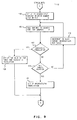
- In the above, the overall reordering operation has been briefly described. In referring to Fig. 4, the reordering operation is set forth in greater detail. When an EBCDIC code is read out of
text storage buffer 8 alongline 21 to graphicset reordering block 15 in Fig. 2, a test, represented bylogic sequence 61, identifies whether the code map read out of the unit control block is available to the graphic set reordering algorithm identified byblock 15 in Fig. 2. If not, the reordering sequence is terminated. The code maps available are identified byblocks reordering block 15 alongline 13 has indicated map number 1 (18 in Fig. 2). If thecode map 1 is available, a test represented bylogic sequence 62 is made to determine whether the EBCDIC code is a graphic (character) code. If not, the graphic set reordering operation or sequence is terminated. The reason is that if the code is not a graphic, then it is a control to which the reordering operation is not applicable. If the code read out of the text storage buffer is a graphic code, then a subtraction operation is performed as indicated bylogic sequence number 63. Following the subtraction operation,logic sequence 64 causes a conversion of the hexadecimal result to decimal for indexing into Table V. Following indexing into Table V to obtain a reorder number, a translation operation may be in order. If the printer is EBCDIC driven and the recorder number indicates an invariant character, the recorder number serves as a gating term for gating the code for the "a" read out of buffer to buffer 10. If the printer is not EBCDIC driven or the character is variant, a translation operation indicated bylogic sequence 65 is performed. -
Translation logic sequence 65 is more fully described in detail in Figs. 8-12.Logic sequence 65 and the details set forth in Figs. 8-12 make up the algorithm ofblock 17 in Fig. 2. Before, the structure of the translation tables inblock 22 ofsection 7 will be described. With reference to Figs. 5-7. - In Fig. 5 there is shown a storage table having stored therein, beginning at the top, the number of available invariant graphics. This number is dependent upon the printer in use. Next in the table appears an offset to print element tables which will be described with reference to Fig. 6. Thereafter, code maps shown in Fig. 2 set out in Tables V, VI, and VII appear in the table, followed by a composite character table shown in more detail in Fig. 7. Next is stored a length of the invariant printer table and the invariant printer table shown in Fig. 7, followed by the variant printer code table shown in Fig. 7. The portion of the table shown in Fig. 5 beginning with the composite character table and extending through the variant printer code table is included in
block 22 of Fig. 2. - Refer next to Fig. 6 which illustrates a print element table, an offset to which is referred to in Fig. 5. In Fig. 6, the table is made up, in order, of 1) the number of print element tables illustrated in Fig. 7, 2) the print element table total length, 3) a code map identifica- tion code which can represent any one of maps 1-3 (Tables V-VII), 4) the number of graphic set identification codes, 5) a list of the graphic set identification codes available for use and supported by a particular print element, 6) the number of reorder numbers, i.e., how many variant graphics, and 7) a listing of the variant graphic reorder numbers. All of the print element table illustrated in Fig. 6 forms part of
block 22 in Fig. 2. - Refer next to Fig. 7. In this figure is illustrated in the upper left hand corner a code map table 71 in which is stored any one of the contents of code maps 13. Depending upon which one of code maps 1-3 is stored in code map table 71, and the particular printer in use, pointers will be provided to invariant printer code table 72 and print element tables 73. With the exception of code map table 71, the remainder of Fig. 7 is included in
block 22 of Fig. 2. Code map table 71 is included in eitherblock - With the above structure in mind, the operations performed by
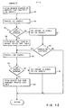
processor 60 under the control of the program or algorithm contained inblock 17 of Fig. 2 will be described. These operations are set forth in detail in Figs. 8-12. Referring first to Fig. 8, logic sequences 61-64 are indentical to those illustrated in Fig. 4. If a code map is not available and the character in EBCDIC code applied alongline 21 is not a graphic, translation is not possible and the operation is terminated. This is illustrated bylogic sequence 81 in Fig. 10. - Following obtaining a reorder number by
logic sequence 64, a test is performed by logic sequence 82 to determine if the character falls into an invariant graphic category. If there is a positive result of the test performed in logic sequence 82, a test is performed bylogic sequence 83 to determine if the printer in use is an EBCDIC code driven printer. If so, the previously obtained reorder number is used as an ANDing condition for gating the EBCDIC code applied alongline 21 to buffer 10 for ultimately driving the printer to print the character. This is indicated bylogic sequence 84. If not,logic sequence 85 causes a printer code to be obtained from invariant printer code table 72 in Fig. 7. Upon obtaining the printer code from invariant printer code table 72,logic sequence 86 in Fig. 10 transmits the code to buffer 10. - If the result of the test performed by logic sequence 82 is negative, a test is performed by
logic sequence 87 to determine if the character appearing online 21 exists on the print element on the printer. A point to note here is that a selected print element may support a plurality of keyboards. The variant print element table of Fig. 6 (denoted byreference numeral 73 in Fig. 7) is examined to find a table which supports the active graphic set (keyboard) identification code. This is indicated bylogic sequence 88 in Fig. 10. Assuming that the graphic set identification code or keyboard identification code is supported as indicated bylogic sequence 89, a search is made to find the character as indicated bylogic sequence 90. This operation is a forerunner to the operation of constructing a character. - Refer next to Fig. 11.
Logic sequence 91 calls for a scanning of the variant reorder numbers in print element tables 73 for a reorder number of the character. A test is made inlogic sequence 92 to determine if the reorder number for the character is present. If the character is not found, a determination, as indicated bylogic sequence 93, is made as to whether the character falls into a composite category.Logic sequence 94 causes a routing to the composite character operations shown in Fig. 12. In this figure,logic sequence 95 causes the reorder number of graphics that can be used to construct the character to be obtained. The graphic reorder numbers which can be used to construct the character are set out in the composite character table 75 in Fig. 7. Assume for a moment that the reorder number from tables 73 is 190. In this case, the beginning of the composite category 155 is substracted from 190. The result is 35 which is multiplied by 2 to provide an index of 70. The index of 70 is used as a pointer into the composite character table 75. Located in the composite character table are two side-by-side reorder numbers. Assume that the first for a "0" is 42 and the second is 66. Reorder number 42 is invariant, and therefore, can be translated. In this case, reorder number 42 is used to index invariant printer code table 72. It is to be further assumed that located at the index position in the invariant printer code table 72 is X'59'. X'59' provides the tilt/rotate information for printing with a golf ball type printer. The second reorder number in the composite character table 75 was 66. This is the reorder number of a "/" and falls within a variant category. In this case, the variant print element table 73 is indexed to position 66. The index position of the reorder number in the variant reorder number list of the print element table 73 is then used to index into the variant printer code table 74 to obtain a hexadecimal code for causing the printer to perform the correct tilt/rotate operation. Although alluded to earlier, it is to be specifically pointed out that the hexadecimal codes read out of both the invariant and variant printer code tables are different than the hexadecimal codes read out of both the invariant and variant printer code tables are different than the hexadecimal codes read fromtext storage buffer 8. - That is, a "0" is stored in
text storage buffer 8 in a binary equivalent to X'80'. Based on the above assumptions, the hexadecimal codes read out of the invariant printer code table are X'59' and X'09', respectively, for causing correct tilt and rotate. In the event a daisy wheel printer is being utilized, the reorder numbers 42 and 66 read out of the composite character table 75 are used respectively as gating terms for gating the appropriate hexadecimal codes to buffer 10. - Referring again to Fig. 12,
logic sequence 96 calls for processing the first character. Processing the first character involves a test bylogic sequence 97 to determine if the first character read out of the composite character table 75 in Fig. 7 is invariant. If so, the operations described above are repeated. -
Logic sequence 98 causes the printer code from the -invariant printer code table to be obtained. In the event that the first character in the composite character table 75 is not invariant, the events called oflogic sequence 90 are called for. It is to be noted thatlogic sequence 90 appears both in Figs. 10 and 12. This results inlogic sequence 91 in Fig. 11 being called for. - Thereafter, a test is made in
logic sequence 99 to determine if there has been a successful translation operation. If not, the character cannot be constructed with the print element. If there has been a successful translation operation, the second character in the composite character table 75 is processed. This is indicated bylogic sequence 100. Processing of the second character first involves a test inlogic sequence 101 to determine if the second character is invariant. If not,logic sequence 90 is again called for. If the second character is invariant,logic sequence 102 causes the printer code from the invariant printer code table 74 in Fig. 7 to be sought. If a successful translation has taken place as indicated by the test inlogic sequence 103 in Fig. 11,logic sequence 104 causes the system to set up for successful translation and operation is returned tologic sequence 90 in Fig. 10. A successful translation simply means that a reorder number has been found. Following the test inlogic sequence 103, if there has not been a successful translation then the operation oflogic sequence 105 are performed and operation returns tologic sequence 90 in Fig. 10. - The operations of searching for a reoder number are illustrated in Fig. 9.
Logic sequence 106 causes a setup to search for a variant reorder number in print element table 73 in Fig. 7. This results in the operations performed bylogic sequence 90 again being performed. If a reorder number has been found as indicated by the test inlogic sequence 107 the first graphic set identification (keyboard identification) in the print element table is set up to indicate to the operator the print element to mount to print the character. This operation is indicated bylogic sequence 108. In the event a reorder number has not been found by the test indicated inlogic sequence 107, a test is performed bylogic sequence 109 to determine if all print element tables have been searched. If not,logic sequence 110 causes an incrementing to the next print element table and the operations oflogic sequence 90 are again performed. If in the event all tables have been searched, provision is made to handle the circumstances of an unsuccessful translation as indicated bylogic sequence 111. - Referring again to Fig. 11 and the test indicated by
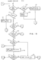
logic sequence 92, if the character is a member of the keyboard identification, the index position in the variant reorder number list of the print element table is calculated as indicated bylogic sequence 112. Thereafter, the printer code from the variant printer code table is sought as indicated bylogic sequence 113. - Reference is next made to Figs. 13 and 14. In these figures are depicted the operations leading to a prompting or signalling of an operator for a print element change in the event a character cannot be printed. As indicated earlier, at the beginning of a document there exist multi-byte control codes. One of these codes is used to denote the keyboard identification. A test is made in
logic sequence 114 to determine if the code is a control code. If not, a test is made inlogic sequence 115 to determine if the code read alongline 21 is a character. If not, any single byte control code or codes are processed as indicated bylogic sequence 116. Thereafter, a determination in made bylogic sequence 117 in Fig. 14 as to whether the document has been completed. If so, the operation is terminated. If not, the test performed bylogic sequence 114 is repeated. If the results of the test inlogic sequence 115 are positive, a test is made inlogic sequence 118 to determine if the character is supported by the active keyboard. That is, a determination is made as to whether the character exists on the mounted print element. If so, the printer code for printer in use is loaded intoline buffer 10 in Fig. 2. This is indicated bylogic sequence 119 in Fig. 14. - In the event the results of the test performed by
logic sequence 114 are that the multi-byte control read alongline 21 is a keyboard identification change (as indicated by logic sequence 120), the keyboard identification code is stored in a deferred keyboard identification code register as indicated bylogic sequence 121. Thereafter, a test is made inlogic sequence 117 to determine if the document has been completed. If the multi-byte control appearing online 21 is not a keyboard identification change, the multi-byte control is processed as indicated bylogic sequence 122. - Turning to the test performed by
logic sequence 118 if the character read alongline 21 is not supported by the keyboard, a test is made to determine whether there is a comparison between the active keyboard and the keyboard identification code stored in the deferred keyboard identification code register. This test is performed bylogic sequence 123. If the results of the test performed bylogic sequence 123 are negative, the character read alongline 21 is processed bylogic sequence 126. If the results of the test performed bylogic sequence 123 are positive, a test is performed bylogic sequence 124 to determine if the character exists on the keyboard stored in the deferred keyboard identification register. The register utilized for storing a deferred keyboard identification code can exist either in the processor or insection 6 in Fig. 2. If the results of the test performed bylogic sequence 124 are positive, the operator is prompted to install a proper print element. This is indicated bylogic sequence 125. Following prompting of the need for a new print element, the appropriate printer code is inserted into line buffer as indicated bylogic sequence 119. In the event the character does not exist on a print element identified by a deferred keyboard identification code, a search is made of available keyboards (print element tables) to obtain the particular character. This is represented bylogic sequence 126. In the event a keyboard is not available to the system, as indicated by the test performed bylogic sequence 127, an underscore code is substituted for the non-processable character as indicated bylogic sequence 128. On the other hand, if there is a keyboard available to the system, the operator is prompted to install a proper print element as indicated bylogic sequence 125. - The following is both a summary of the more salient features of the above, and includes details not heretofore mentioned.
- The print element tables 73 contain a list of reorder numbers that present the graphics supported by the EBCDIC code maps of Tables 1-3. These are the characters available to the system. Each unique graphic on the code maps supported by the machine is represented by a unique reorder number ranging from 0-255. The print element tables are 192 bytes in length. Each contains the reorder numbers of the graphics that make up the code map graphic set. The reorder number for a graphic is placed in the table location that corresponds to the EBCDIC code minus X'40'. As pointed out earlier, a lower case "a" is represented as X'81', and its reorder number of 41 is in
position 65 in all print element tables. As such, this character is invariant. - The print element tables are an integral part of the translation operations. Obtaining a reorder number determines the character category. If the category is invariant, the reorder number is added to the top of the invariant printer code table and the contents of that location are the printer code that is to be output to the printer for that graphic. If the category is variant, the use of additional tables is required. The composite character table contains two reorder numbers per constructable graphic. The reorder numbers are the reorder numbers of the two graphics that can be used to construct the character read from
buffer 8. The table contains the reorder number of the overstruck graphic in the first position and the reorder number of the overstriking graphic in the second position. The reorder number that begins the composite graphics is subtracted from the reorder number of the composite graphic. The result is multiplied by two to obtain the location of the two reorder numbers that are used to construct the graphic. - The IPCT length byte in Fig. 5 is used to determine if the printer code type is something other than EBCDIC. If this byte contains a zero, the EBCDIC code is used to determine the printer code for the graphic.
- The invariant printer code table 72 contains the printer specific codes that represent the characters that are on all print elements and have the same code on all print elements for a particular printer. The alphabetics, nume- rics and some special characters such as period, comma, slash, ETC., will cause invariant printer code table 72 to be indexed from table 71. The size of table 72 will vary dependent on the printer. The contents of table VII in Annex will be tilt-rotate codes for a golf ball printer. Table 72 is not required for EBCDIC driven printers.
- The variant printer code table 74 contains the printer specific codes that represent the characters that are not on all print elements or have different codes or various print elements for a particular printer. The reorder numbers found in table 71 that represent variant graphics will cause table 71 to index tables 73 for translation operations. The position of the reorder number in tables 73 will be used as an index into this table to obtain the code that should be sent to the printer (buffer 10) for the graphic. The size of table 73 will.vary dependent on the printer. The contents of table 73 will be tilt-rotate codes. Table 74 is not needed by an EBCDIC driven printer.
- Tables 73 contain the variant reorder numbers of those graphics that exist on the print element. When a variant character is to be translated, the keyboard identification codes in Table 73 are requested for the active keyboard to determine if a print element table exists for the keyboard.
- If the keyboard identification code is found, tables 73 are used to determine if the graphic is on the element. The reorder number of the graphic is searched for in tables 73. If the reorder number is found, a successful translation has occurred in that a proper printer is available. If the keyboard identification code or reorder number are not found, an unsuccessful translation has occurred. In this case, all of the tables 73 are searched to determine if the graphic can be supported (printed).
- The reorder numbers are ordered in tables 73 according to the position of the code that should be output for the graphic in table 74. The code that is to be output for a graphic will vary dependent on the print element in use. Therefore, each one of tables 73 is customized for a print element. The position where the reorder number is found is used as an index into table 74 to determine the graphic printer code. The length of the tables will vary dependent on the printer in use.
- If the reorder number is not found in the active one of tables 73, a determination is made as to whether the graphic can be constructed. Reorder numbers 155-255 represent those graphics that can be constructed. If the graphic can be constructed, the reorder number is used to index into table 75 to obtain the two reorder numbers representing the graphics that can be used to construct the called for graphic. If these two reorder numbers are either invariant or variant and found in the active one of tables 73, the variant reorder number is used to index into table 72 and the index position of the variant graphic(s) is used to obtain the printer code(s) that are to be output to the printer. If the variant reorder numbers from the composite table cannot be found in the active one of tables 73, another one of tables 73 is searched for the graphic.
- Refer next to Fig. 15. The structure included in this figure is similar to that shown in Fig. 2. The primary distinctions are an
input line 130 totranslation algorithm 17, and anoutput line 131 to a floppydisk storage device 132. For this figure, it is to be assumed that incoming data is applied alongline 130 from a communication device. The object therefore, is to convert the communication device code to EBCDIC for storage intext buffer 8 and ultimate transfer alongline 131 to floppydisk storage device 132. Since the operations performed are obvious in view of the above description, they will only be briefly described below. - The incoming device code is first applied to
translation algorithm block 17, and a reorder number is sought for converting to an EBCDIC code for storage inbuffer 8. It is to be noted that the algorithm ofblocks program diskette 133 alongline 134 to controlblock 9. Inblock 9, the algorithms are available toprocessor 60 on an as needed basis. - While the invention has been particularly shown and described with reference to a particular embodiment, it will be understood by those skilled in the art that various changes in form and detail may be made without departing from the spirit and scope of the invention.
-


Claims (6)
Applications Claiming Priority (2)
| Application Number | Priority Date | Filing Date | Title |
|---|---|---|---|
| US208748 | 1980-11-20 | ||
| US06/208,748 US4359286A (en) | 1980-11-20 | 1980-11-20 | Character set expansion |
Publications (2)
| Publication Number | Publication Date |
|---|---|
| EP0052725A1 true EP0052725A1 (en) | 1982-06-02 |
| EP0052725B1 EP0052725B1 (en) | 1985-07-03 |
Family
ID=22775892
Family Applications (1)
| Application Number | Title | Priority Date | Filing Date |
|---|---|---|---|
| EP81107926A Expired EP0052725B1 (en) | 1980-11-20 | 1981-10-05 | Method of reducing the print element changes in a text processing system |
Country Status (5)
| Country | Link |
|---|---|
| US (1) | US4359286A (en) |
| EP (1) | EP0052725B1 (en) |
| JP (1) | JPS57114938A (en) |
| CA (1) | CA1162318A (en) |
| DE (1) | DE3171239D1 (en) |
Cited By (7)
| Publication number | Priority date | Publication date | Assignee | Title |
|---|---|---|---|---|
| EP0063938A2 (en) * | 1981-04-29 | 1982-11-03 | Ing. C. Olivetti & C., S.p.A. | Typing device |
| EP0063939A2 (en) * | 1981-04-29 | 1982-11-03 | Ing. C. Olivetti & C., S.p.A. | Typing arrangement |
| FR2553208A1 (en) * | 1983-10-11 | 1985-04-12 | Canon Kk | IMAGE DATA OUTPUT APPARATUS |
| GB2156557A (en) * | 1984-01-17 | 1985-10-09 | Sharp Kk | Word processor |
| EP0203411A2 (en) * | 1985-05-03 | 1986-12-03 | Minolta Camera Kabushiki Kaisha | Word processor with multiple printing modes of operation |
| EP0249794A2 (en) * | 1986-06-20 | 1987-12-23 | Lexmark International, Inc. | Automatic stop code insertion feature for a word processing apparatus |
| GB2239116A (en) * | 1989-11-20 | 1991-06-19 | Brother Ind Ltd | Printing apparatus |
Families Citing this family (14)
| Publication number | Priority date | Publication date | Assignee | Title |
|---|---|---|---|---|
| BE891911A (en) * | 1982-01-27 | 1982-05-17 | Europ Agence Spatiale | DIGITAL DEVICE FOR CONTROLLING THE GRAPHIC REPRESENTATION OF CHARACTERS |
| JPS58219591A (en) * | 1982-06-15 | 1983-12-21 | キヤノン株式会社 | Display unit |
| US4594674A (en) * | 1983-02-18 | 1986-06-10 | International Business Machines Corporation | Generating and storing electronic fonts |
| DE3436033C2 (en) * | 1983-09-30 | 1997-05-07 | Canon Kk | Output device and method for outputting character patterns |
| US4710886A (en) * | 1984-10-24 | 1987-12-01 | International Business Machines Corporation | Table driven print formatting |
| GB2167013B (en) * | 1984-10-31 | 1989-04-05 | Canon Kk | Printer |
| EP0215929A1 (en) * | 1985-03-29 | 1987-04-01 | LO, Shui-Yin | Improved method and apparatus for specifying and forming characters |
| US4749989A (en) * | 1985-06-03 | 1988-06-07 | Honeywell Bull Inc. | Word processing composite character processing method |
| US4942541A (en) * | 1988-01-22 | 1990-07-17 | Oms, Inc. | Patchification system |
| US5562350A (en) * | 1988-04-18 | 1996-10-08 | Canon Kabushiki Kaisha | Output apparatus that selects a vector font based on character size |
| US4862950A (en) * | 1988-11-22 | 1989-09-05 | Gribble Robert L | Apparatus and method for controlling the environment in a substantially enclosed and pressurized work area such as a textile manufacturing plant |
| JPH0812632B2 (en) * | 1992-04-30 | 1996-02-07 | インターナショナル・ビジネス・マシーンズ・コーポレイション | Information system and information method |
| JP2525333B2 (en) * | 1993-09-06 | 1996-08-21 | キヤノン株式会社 | Output device |
| US8484170B2 (en) * | 2011-09-19 | 2013-07-09 | International Business Machines Corporation | Scalable deduplication system with small blocks |
Citations (4)
| Publication number | Priority date | Publication date | Assignee | Title |
|---|---|---|---|---|
| US3892303A (en) * | 1973-04-03 | 1975-07-01 | Frederick P Willcox | Type font changing mechanism and controls |
| US4026403A (en) * | 1975-02-14 | 1977-05-31 | Hitachi, Ltd. | Automatic printer with plurality of replaceable printing members |
| GB2015789A (en) * | 1978-03-06 | 1979-09-12 | Ibm | Automatic playout system and method |
| GB2072388A (en) * | 1980-03-20 | 1981-09-30 | Qume Corp | Printing apparatus |
Family Cites Families (18)
| Publication number | Priority date | Publication date | Assignee | Title |
|---|---|---|---|---|
| US4228507A (en) * | 1968-07-02 | 1980-10-14 | Carl Leban | Methods and means for reproducing non-alphabetic characters |
| US3546681A (en) * | 1969-01-30 | 1970-12-08 | Rca Corp | Programmed method for manipulating electronic fonts in electronic photocomposition systems |
| US3711849A (en) * | 1971-03-08 | 1973-01-16 | Vector General | Character font generating system for cathode-ray tube displays, or the like |
| US3729730A (en) * | 1971-04-14 | 1973-04-24 | Cogar Corp | Display system |
| US4029947A (en) * | 1973-05-11 | 1977-06-14 | Rockwell International Corporation | Character generating method and system |
| US4005390A (en) * | 1974-11-11 | 1977-01-25 | International Business Machines Corporation | Merger and multiple translate tables in a buffered printer |
| US3964591A (en) * | 1975-06-10 | 1976-06-22 | International Business Machines Corporation | Font selection system |
| US4193119A (en) * | 1977-03-25 | 1980-03-11 | Xerox Corporation | Apparatus for assisting in the transposition of foreign language text |
| US4300206A (en) * | 1977-06-30 | 1981-11-10 | International Business Machines Corporation | Flexible text and image generator for a raster printer |
| US4298945A (en) * | 1978-05-12 | 1981-11-03 | Eltra Corporation | Character generating method and apparatus |
| US4262338A (en) * | 1978-05-19 | 1981-04-14 | Gaudio Jr John J | Display system with two-level memory control for display units |
| US4220417A (en) * | 1978-06-08 | 1980-09-02 | International Business Machines Corporation | Apparatus for producing preliminary character printout of text and instruction codes of word processing apparatus |
| US4251871A (en) * | 1978-09-29 | 1981-02-17 | International Business Machines Corporation | Method and apparatus for storing and reconstructing Chinese-like characters |
| JPS5925663B2 (en) * | 1979-02-26 | 1984-06-20 | 株式会社リコー | Print control method |
| US4298957A (en) * | 1979-06-28 | 1981-11-03 | Xerox Corporation | Data processing system with character sort apparatus |
| US4274079A (en) * | 1979-07-12 | 1981-06-16 | Burroughs Corporation | Apparatus and method for dynamic font switching |
| US4261039A (en) * | 1979-10-19 | 1981-04-07 | International Business Machines Corporation | Microprocessor controlled positioning system |
| US4286329A (en) * | 1979-12-17 | 1981-08-25 | International Business Machines Corporation | Complex character generator |
-
1980
- 1980-11-20 US US06/208,748 patent/US4359286A/en not_active Expired - Lifetime
-
1981
- 1981-09-18 JP JP56146422A patent/JPS57114938A/en active Granted
- 1981-09-30 CA CA000387015A patent/CA1162318A/en not_active Expired
- 1981-10-05 DE DE8181107926T patent/DE3171239D1/en not_active Expired
- 1981-10-05 EP EP81107926A patent/EP0052725B1/en not_active Expired
Patent Citations (5)
| Publication number | Priority date | Publication date | Assignee | Title |
|---|---|---|---|---|
| US3892303A (en) * | 1973-04-03 | 1975-07-01 | Frederick P Willcox | Type font changing mechanism and controls |
| US4026403A (en) * | 1975-02-14 | 1977-05-31 | Hitachi, Ltd. | Automatic printer with plurality of replaceable printing members |
| GB2015789A (en) * | 1978-03-06 | 1979-09-12 | Ibm | Automatic playout system and method |
| US4205922A (en) * | 1978-03-06 | 1980-06-03 | International Business Machines Corporation | Font and column format control system |
| GB2072388A (en) * | 1980-03-20 | 1981-09-30 | Qume Corp | Printing apparatus |
Non-Patent Citations (2)
| Title |
|---|
| IBM Technical Disclosure Bulletin, Vol. 22, No. 5, October 1979, New York (US) D.J. MOORE et al.: "Optimum Order of Print Wheel Selection in a Multi-Font Impact Printer" page 1754 * the whole document * * |
| IBM Technical Disclosure Bulletin, Vol. 9, No. 11, April 1967, New York (US) R.S. HEARD et al.: "Text Composition with Numerous Accents" page 1578 * the whole document * * |
Cited By (13)
| Publication number | Priority date | Publication date | Assignee | Title |
|---|---|---|---|---|
| EP0063938A2 (en) * | 1981-04-29 | 1982-11-03 | Ing. C. Olivetti & C., S.p.A. | Typing device |
| EP0063939A2 (en) * | 1981-04-29 | 1982-11-03 | Ing. C. Olivetti & C., S.p.A. | Typing arrangement |
| EP0063939A3 (en) * | 1981-04-29 | 1982-12-29 | Ing. C. Olivetti & C., S.P.A. | Typing arrangement |
| EP0063938A3 (en) * | 1981-04-29 | 1983-01-12 | Ing. C. Olivetti & C., S.P.A. | Typing device |
| FR2553208A1 (en) * | 1983-10-11 | 1985-04-12 | Canon Kk | IMAGE DATA OUTPUT APPARATUS |
| GB2156557A (en) * | 1984-01-17 | 1985-10-09 | Sharp Kk | Word processor |
| EP0203411A2 (en) * | 1985-05-03 | 1986-12-03 | Minolta Camera Kabushiki Kaisha | Word processor with multiple printing modes of operation |
| EP0203411A3 (en) * | 1985-05-03 | 1989-01-18 | Minolta Camera Kabushiki Kaisha | Word processor with multiple printing modes of operation |
| EP0249794A2 (en) * | 1986-06-20 | 1987-12-23 | Lexmark International, Inc. | Automatic stop code insertion feature for a word processing apparatus |
| EP0249794A3 (en) * | 1986-06-20 | 1989-02-22 | International Business Machines Corporation | Automatic stop code insertion feature for a word processing apparatus |
| US4894798A (en) * | 1986-06-20 | 1990-01-16 | International Business Machines Corporation | Automatic stop code insertion feature for a word processing apparatus |
| GB2239116A (en) * | 1989-11-20 | 1991-06-19 | Brother Ind Ltd | Printing apparatus |
| US5299872A (en) * | 1989-11-20 | 1994-04-05 | Brother Kogyo Kabushiki Kaisha | Printing machine with single line type face |
Also Published As
| Publication number | Publication date |
|---|---|
| EP0052725B1 (en) | 1985-07-03 |
| JPH0218987B2 (en) | 1990-04-27 |
| DE3171239D1 (en) | 1985-08-08 |
| CA1162318A (en) | 1984-02-14 |
| JPS57114938A (en) | 1982-07-17 |
| US4359286A (en) | 1982-11-16 |
Similar Documents
| Publication | Publication Date | Title |
|---|---|---|
| EP0052725B1 (en) | Method of reducing the print element changes in a text processing system | |
| US4689768A (en) | Spelling verification system with immediate operator alerts to non-matches between inputted words and words stored in plural dictionary memories | |
| EP0089468B1 (en) | Abbreviated typing with special form display | |
| US4807181A (en) | Dictionary memory with visual scanning from a selectable starting point | |
| US4510567A (en) | Qualifying and sorting file record data | |
| GB2097974A (en) | Spelling error detector apparatus and methods | |
| US4092729A (en) | Apparatus for automatically forming hyphenated words | |
| US4454592A (en) | Prompt line display in a word processing system | |
| US4393463A (en) | Insertion of character set change codes in an altered text stream | |
| EP0042045B1 (en) | Automatic line justification process' in a text processing system comprising a plurality of printers | |
| EP0039393B1 (en) | Text recorder with automatic word ending and method of operating the same | |
| EP0315957B1 (en) | Word processor | |
| CA1209274A (en) | Context redundancy text compression | |
| EP0097818B1 (en) | Spelling verification method and typewriter embodying said method | |
| US5018883A (en) | Vector font processing in a printing device | |
| EP0119396B1 (en) | Apparatus for and methods of presenting or displaying data represented as electric signals | |
| US4402058A (en) | Keyboard mismatch correction | |
| GB2189913A (en) | Word processor | |
| EP0052757A2 (en) | Method of decoding phrases and obtaining a readout of events in a text processing system | |
| US5404517A (en) | Apparatus for assigning order for sequential display of randomly stored titles by comparing each of the titles and generating value indicating order based on the comparison | |
| EP0065114B1 (en) | Method of qualifying and sorting file record data in a text processing system | |
| JP2535059B2 (en) | Character processor | |
| EP0077891B1 (en) | System for formatting justified lines of text containing complex characters | |
| JP3577741B2 (en) | Character input device | |
| US5002409A (en) | Printer with underlining function |
Legal Events
| Date | Code | Title | Description |
|---|---|---|---|
| PUAI | Public reference made under article 153(3) epc to a published international application that has entered the european phase |
Free format text: ORIGINAL CODE: 0009012 |
|
| 17P | Request for examination filed |
Effective date: 19811005 |
|
| AK | Designated contracting states |
Designated state(s): BE CH DE FR GB IT NL SE |
|
| ITF | It: translation for a ep patent filed |
Owner name: IBM - DR. ARRABITO MICHELANGELO |
|
| GRAA | (expected) grant |
Free format text: ORIGINAL CODE: 0009210 |
|
| AK | Designated contracting states |
Designated state(s): BE CH DE FR GB IT LI NL SE |
|
| PG25 | Lapsed in a contracting state [announced via postgrant information from national office to epo] |
Ref country code: NL Effective date: 19850703 |
|
| PG25 | Lapsed in a contracting state [announced via postgrant information from national office to epo] |
Ref country code: SE Effective date: 19850730 |
|
| REF | Corresponds to: |
Ref document number: 3171239 Country of ref document: DE Date of ref document: 19850808 |
|
| ET | Fr: translation filed | ||
| PG25 | Lapsed in a contracting state [announced via postgrant information from national office to epo] |
Ref country code: LI Effective date: 19851031 Ref country code: CH Effective date: 19851031 |
|
| NLV1 | Nl: lapsed or annulled due to failure to fulfill the requirements of art. 29p and 29m of the patents act | ||
| PLBE | No opposition filed within time limit |
Free format text: ORIGINAL CODE: 0009261 |
|
| STAA | Information on the status of an ep patent application or granted ep patent |
Free format text: STATUS: NO OPPOSITION FILED WITHIN TIME LIMIT |
|
| REG | Reference to a national code |
Ref country code: CH Ref legal event code: PL |
|
| 26N | No opposition filed | ||
| PGFP | Annual fee paid to national office [announced via postgrant information from national office to epo] |
Ref country code: FR Payment date: 19911001 Year of fee payment: 11 |
|
| ITTA | It: last paid annual fee | ||
| PGFP | Annual fee paid to national office [announced via postgrant information from national office to epo] |
Ref country code: DE Payment date: 19911102 Year of fee payment: 11 |
|
| PGFP | Annual fee paid to national office [announced via postgrant information from national office to epo] |
Ref country code: BE Payment date: 19920923 Year of fee payment: 12 |
|
| PGFP | Annual fee paid to national office [announced via postgrant information from national office to epo] |
Ref country code: GB Payment date: 19920925 Year of fee payment: 12 |
|
| PG25 | Lapsed in a contracting state [announced via postgrant information from national office to epo] |
Ref country code: FR Effective date: 19930630 |
|
| PG25 | Lapsed in a contracting state [announced via postgrant information from national office to epo] |
Ref country code: DE Effective date: 19930701 |
|
| REG | Reference to a national code |
Ref country code: FR Ref legal event code: ST |
|
| PG25 | Lapsed in a contracting state [announced via postgrant information from national office to epo] |
Ref country code: GB Effective date: 19931005 |
|
| PG25 | Lapsed in a contracting state [announced via postgrant information from national office to epo] |
Ref country code: BE Effective date: 19931031 |
|
| BERE | Be: lapsed |
Owner name: INTERNATIONAL BUSINESS MACHINES CORP. Effective date: 19931031 |
|
| GBPC | Gb: european patent ceased through non-payment of renewal fee |
Effective date: 19931005 |