EP0056654A1 - Fuel cell system and method for producing steam in a fuel cell system - Google Patents
Fuel cell system and method for producing steam in a fuel cell system Download PDFInfo
- Publication number
- EP0056654A1 EP0056654A1 EP82100369A EP82100369A EP0056654A1 EP 0056654 A1 EP0056654 A1 EP 0056654A1 EP 82100369 A EP82100369 A EP 82100369A EP 82100369 A EP82100369 A EP 82100369A EP 0056654 A1 EP0056654 A1 EP 0056654A1
- Authority
- EP
- European Patent Office
- Prior art keywords
- gas
- fuel
- process gas
- fuel cell
- exhausted
- Prior art date
- Legal status (The legal status is an assumption and is not a legal conclusion. Google has not performed a legal analysis and makes no representation as to the accuracy of the status listed.)
- Granted
Links
Images
Classifications
-
- H—ELECTRICITY
- H01—ELECTRIC ELEMENTS
- H01M—PROCESSES OR MEANS, e.g. BATTERIES, FOR THE DIRECT CONVERSION OF CHEMICAL ENERGY INTO ELECTRICAL ENERGY
- H01M8/00—Fuel cells; Manufacture thereof
- H01M8/06—Combination of fuel cells with means for production of reactants or for treatment of residues
- H01M8/0606—Combination of fuel cells with means for production of reactants or for treatment of residues with means for production of gaseous reactants
- H01M8/0612—Combination of fuel cells with means for production of reactants or for treatment of residues with means for production of gaseous reactants from carbon-containing material
-
- Y—GENERAL TAGGING OF NEW TECHNOLOGICAL DEVELOPMENTS; GENERAL TAGGING OF CROSS-SECTIONAL TECHNOLOGIES SPANNING OVER SEVERAL SECTIONS OF THE IPC; TECHNICAL SUBJECTS COVERED BY FORMER USPC CROSS-REFERENCE ART COLLECTIONS [XRACs] AND DIGESTS
- Y02—TECHNOLOGIES OR APPLICATIONS FOR MITIGATION OR ADAPTATION AGAINST CLIMATE CHANGE
- Y02E—REDUCTION OF GREENHOUSE GAS [GHG] EMISSIONS, RELATED TO ENERGY GENERATION, TRANSMISSION OR DISTRIBUTION
- Y02E60/00—Enabling technologies; Technologies with a potential or indirect contribution to GHG emissions mitigation
- Y02E60/30—Hydrogen technology
- Y02E60/50—Fuel cells
Definitions
- This invention pertains to fuel cell systems and, in particular, to fuel cell systems which utilize steam.
- Fuel cell systems often utilize high pressure steam for reforming reaction (fuel processing) and for use as process steam for waste heat utilization.
- reforming reaction the steam is combined with a hydrocarbon fuel and the combination applied to a reformer which provides at its output fuel process gas to be used in the fuel cell or fuel cell stack of the system.
- U.S. patent 3,969,145 discloses one steam generating practice wherein use is made of the heated oxidant and fuel process.gases passing through the system fuel cell.
- Metallic tubes carrying coolant water are situated internal to the cell stack and in heat exchanging relationship with the respective flows of fuel and oxidant gases. The water in the tubes is thereby heated to produce steam which is also simultaneously heated in the same manner. The steam is then removed from the tubes and used elsewhere in the system as, for example, in steam reforming reaction of the type described above.
- the above and other objectives are realized in a fuel cell system wherein process gas exhausted from the fuel cell of the system is heated to a temperature sufficient to produce a predetermined amount of steam at a predetermined pressure by gas at a higher temperature generated elsewhere in the system.
- the heating of the exhausted process gas occurs in a heat exchanger external to the cell and the resultant gas is then utilized to produce the desired steam.
- the fuel cell is operated with excess process gas for cooling the cell to a desired operating temperature and the exhausted cooling process gas is used for steam generation.
- excess oxidant gas is utilized for fuel cell cooling and exhausted oxidant gas for steam generation.
- the fuel cell system I comprises a fuel cell 2 which, preferably, is a phosphoric acid cell, although the principles of the invention extend to other cell types such as, for example, molten carbonate cells and solid oxide cells.
- An anode section 3 and a cathode section 4 communicating with an electrolyte section 50 receive respective fuel process gas and oxidant process gas along input lines 5 and 6, respectively.
- the fuel and oxidant gases are at substantially the same pressure which might, typically, be in the range of 30 to 150 psia, so as to promote fuel cell efficiency.
- the flow of oxidant process gas is further of an amount in excess of that required for electrochemical reaction, the excess gas being of a quantity sufficient to cool the fuel cell to a predetermined temperature promotive of desired fuel cell life.
- the oxidant process gas is derived from a compressor section 7 of a turbocompressor unit 10, the compressor 7 raising the pressure of the oxidant gas from a supply 8 to the desired pressure.
- the fuel process gas is derived from a reformer 9 which receives from a common line 11 a mixture of preheated hydrocarbon fuel and steam coupled to the line 11 by respective lines 12 and 13.
- the hydrocarbon fuel is provided to the line 12 from a compressor section 14 of the turbocompressor 10, the section being fed from a fuel supply 15.
- a pre-heater in the form of a heat exchanger 16 situated in the line 12 preheats the fresh fuel prior to coupling to the common line 11.
- the steam provided to the line 11 from the line 13 must be at least at that pressure, since the steam pressure controls the resultant fuel process gas pressure.
- the steam pressure should be higher than the required fuel process gas pressure, in prder to account for pressure losses in the reformer and in the lines carrying the gas to the anode section 3.
- a certain ratio of steam to fuel is required. For example, with liquid naptha as a fuel, a ratio of 4 moles steam to I mole carbon is desirable. Preferably, that amount of steam should be at a pressure above the fuel gas pressure.
- -steam at the desired pressure and of a desired amount is generated in the fuel cell system utilizing a quantity of excess oxidant gas exhausted from the cathode section 4 and, therefore, at the predetermined fuel cell temperature, and a further quantity of higher temperature. gas derived from elsewhere in the fuel cell system. These gases are carried via lines 18 and 21 to an auxiliary heater or heat exchanger 17, the temperature of the higher temperature gas being sufficient to raise the temperature of the quantity of oxidant gas to that required to produce the desired amount of steam at the desired pressure.
- the increased temperature oxidant gas is, thereafter, applied to a steam generator in the form of a heat exchanger 22 having a pressure valve for allowing steam issuance at the desired pressure. Water from a supply 23 is coupled to the generator 22 and is raised therein to steam at such pressure, the steam then being coupled to the generator output line 24 which feeds steam line 13.
- the higher temperature gas in the line 21 is obtained from gas derived in the fuel cell system from elsewhere than the fuel cell 2. As. shown in dotted line, such gas may be obtained by passage of a portion of the unburned anode gas. exhausted into anode exhaust line 25 through a burner 41, thereby producing gas at a significantly higher temperature than the cell operating temperature.
- gases which also can be used as the higher temperature gas will be pointed out below in the discussion of the remainder of the system 1.
- the reformer 9 is provided with reaction heat from a burner 26 which burns a combination of preheated fresh supply fuel, exhausted fuel gas and compressed oxidant supply gas.
- the latter gases are coupled to the burner 26 via lines 27 and 28, respectively in which are situated heat exchangers 29 and 31 for raising the temperatures of the respective gases.
- the latter exchangers are in stacked relationship with the reformer 9 and the burner 26 and are heated by the burner gas.
- the burner gas is thereafter coupled via line 32 to an exit line 33 which also receives a quantity of exhausted oxidant process gas from the line 19.
- the gas in the line 33 is expanded in a turboexpander section 42 of the turbocompressor 10 and is exhausted from the system via line 34.
- the gas in line 34 also can be coupled to line 21 for providing gas for heating the exhausted oxidant gas coupled to the heat exchanger 17.
- the combined fuel and steam in the line 11 is preheated prior to application to reformer 9 via a heat exchanger 35 to which is also applied the outgoing fuel process gas generated by the reformer.
- the latter gas is thereafter cooled by passage via line 36 through heat exchanger 16 and a high temperature low temperature shift converter 37, the high temperature.converter of which includes a heat exchanger section 38.for heat exchange with the steam in the line 13 prior to coupling to the line 11 and the low temperature converter of which includes a heat exchanger section 39 to which is coupled water from a further water supply 43.
- the fuel process gas is brought to an intermediate temperature by the converter 37 and, as shown, in dotted line, the gas at the output line 44 of the converter is also suitable for coupling to the line 21 for application to the heat exchanger 17 for heating the exhausted oxidant gas coupled thereto.
- a further heat exchanger 45 in the line 44 receives the intermediate temperature fuel process gas and water from a supply 45 further lowering the temperature of same to the predetermined cell temperature for application to the line 5 feeding anode section 3.
- the degree to which the temperature of the exhausted oxidant gas applied to the heat exchanger 17 is to be raised and, thus, the temperature of the higher temperature gas, as well as the amount of exhausted oxidant gas supplied will depend upon the desired pressure and amount of steam to be produced. The latter, in turn, will depend upon system requirements including, amongst other things, the desired fuel cell pressure and operating temperature, as well as the quantity and pressure of steam required in the reformer 9. The particular values of these parameters will of course depend upon each individual application.
- the quantity of exhaust oxidant gas delivered to heat exchanger 17 might be 205 .
- the temperature of the further gas delivered to heat exchanger might be 500 to 1500°F, thereby raising the oxidant gas to a temperature of approximately 400°F. Production of this further gas at such temperature might, in turn, be realized by burning exhausted fuel gas. Alternatively, a similar flow of fuel gas at such temperature from the converter 37 or from the line 34 might also be used.
Abstract
Description
- This invention pertains to fuel cell systems and, in particular, to fuel cell systems which utilize steam.
- Fuel cell systems often utilize high pressure steam for reforming reaction (fuel processing) and for use as process steam for waste heat utilization. In reforming reaction, the steam is combined with a hydrocarbon fuel and the combination applied to a reformer which provides at its output fuel process gas to be used in the fuel cell or fuel cell stack of the system.
- U.S. patent 3,969,145 discloses one steam generating practice wherein use is made of the heated oxidant and fuel process.gases passing through the system fuel cell. Metallic tubes carrying coolant water are situated internal to the cell stack and in heat exchanging relationship with the respective flows of fuel and oxidant gases. The water in the tubes is thereby heated to produce steam which is also simultaneously heated in the same manner. The steam is then removed from the tubes and used elsewhere in the system as, for example, in steam reforming reaction of the type described above.
- It has also been proposed to use the exhausted oxidant gas of the fuel cell system itself for steam generation external to the cell. In this case, the exhausted oxidant gas and water are supplied to a heat exchanger with the resultant production of steam.
- In both the above practices, increased fuel cell temperature is required to provide a desired amount of steam at increased pressures. This can be seen from the equation governing the ratio of generated steam to generating fuel cell gas which is as follows:

- Assuming that the gas stream is at a temperature of 375°F and that steam at 105 psia is required (this corresponds to ts = 332°F and ΔH = 885 Btu/lb) and further that a differential td = 20°F is used and Cp = 0.28 Btu/lb °F, then the ratio Q is calculated as follows:


- For steam at a pressure above 105 psia, the value of tp is increased while the values of ΔH and C p remain substantially the same. As a result, to obtain at the higher pressure the same quantity of steam as obtained at the 105 psia level, the value of the fuel gas temperature to must . be increased by the amount of the increase in the value tp. This of course requires an increase in fuel cell operating temperature.
- At steam pressures of the order of 100 to 180 psi, which pressures are desirable for many fuel cell systems or for many industrial process steam applications, the required increase in fuel cell temperature over conventional temperatures is such as to measurably decrease fuel cell life. As a result, use of the aforesaid practices to provide steam at these high pressures is undesirable.
- One possible alternative to providing the increased pressure steam without raising fuel cell temperature, would be to use a compressor. However, this alternative is undesirable because of cost and power requirement considerations.
- It is therefore an object of the present invention to provide a fuel cell system having an improved capability for generating steam.
- It is a further object of the present invention to provide a fuel cell system capable of providing a given amount of steam at increasing pressures and useable for ' process gas reforming without having to increase fuel cell temperature.
- In accordance with the principles of the present invention, the above and other objectives are realized in a fuel cell system wherein process gas exhausted from the fuel cell of the system is heated to a temperature sufficient to produce a predetermined amount of steam at a predetermined pressure by gas at a higher temperature generated elsewhere in the system. The heating of the exhausted process gas occurs in a heat exchanger external to the cell and the resultant gas is then utilized to produce the desired steam.
- In the preferred form of the invention, the fuel cell is operated with excess process gas for cooling the cell to a desired operating temperature and the exhausted cooling process gas is used for steam generation. In still further preferred form, excess oxidant gas is utilized for fuel cell cooling and exhausted oxidant gas for steam generation.
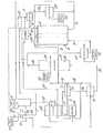
- The above and other features and aspects of the present invention will become more apparent upon reading the following detailed description in conjunction with the accompanying sole drawing which shows a fuel cell system in accordance with the principles of the present invention.
- In FIG. 1, the fuel cell system I comprises a fuel cell 2 which, preferably, is a phosphoric acid cell, although the principles of the invention extend to other cell types such as, for example, molten carbonate cells and solid oxide cells. An anode section 3 and a cathode section 4 communicating with an electrolyte section 50 receive respective fuel process gas and oxidant process gas along
input lines 5 and 6, respectively. In conventional practice, the fuel and oxidant gases are at substantially the same pressure which might, typically, be in the range of 30 to 150 psia, so as to promote fuel cell efficiency. Also, in the present illustrative example, the flow of oxidant process gas is further of an amount in excess of that required for electrochemical reaction, the excess gas being of a quantity sufficient to cool the fuel cell to a predetermined temperature promotive of desired fuel cell life. - The oxidant process gas is derived from a compressor section 7 of a
turbocompressor unit 10, the compressor 7 raising the pressure of the oxidant gas from a supply 8 to the desired pressure. The fuel process gas is derived from areformer 9 which receives from a common line 11 a mixture of preheated hydrocarbon fuel and steam coupled to the line 11 byrespective lines line 12 from a compressor section 14 of theturbocompressor 10, the section being fed from afuel supply 15. A pre-heater in the form of aheat exchanger 16 situated in theline 12 preheats the fresh fuel prior to coupling to the common line 11. - In order for the fuel process gas produced by the
reformer 9 to be at the desired pressure, the steam provided to the line 11 from theline 13 must be at least at that pressure, since the steam pressure controls the resultant fuel process gas pressure. Perferably, the steam pressure should be higher than the required fuel process gas pressure, in prder to account for pressure losses in the reformer and in the lines carrying the gas to the anode section 3. Additionally, to prevent carbon formation in the reformer, a certain ratio of steam to fuel is required. For example, with liquid naptha as a fuel, a ratio of 4 moles steam to I mole carbon is desirable. Preferably, that amount of steam should be at a pressure above the fuel gas pressure. - In accordance with the principles of the present invention, -steam at the desired pressure and of a desired amount is generated in the fuel cell system utilizing a quantity of excess oxidant gas exhausted from the cathode section 4 and, therefore, at the predetermined fuel cell temperature, and a further quantity of higher temperature. gas derived from elsewhere in the fuel cell system. These gases are carried via
lines heat exchanger 17, the temperature of the higher temperature gas being sufficient to raise the temperature of the quantity of oxidant gas to that required to produce the desired amount of steam at the desired pressure. The increased temperature oxidant gas is, thereafter, applied to a steam generator in the form of aheat exchanger 22 having a pressure valve for allowing steam issuance at the desired pressure. Water from asupply 23 is coupled to thegenerator 22 and is raised therein to steam at such pressure, the steam then being coupled to thegenerator output line 24 which feedssteam line 13. - As above-indicated, the higher temperature gas in the
line 21 is obtained from gas derived in the fuel cell system from elsewhere than the fuel cell 2. As. shown in dotted line, such gas may be obtained by passage of a portion of the unburned anode gas. exhausted into anode exhaust line 25 through a burner 41, thereby producing gas at a significantly higher temperature than the cell operating temperature. Other gases which also can be used as the higher temperature gas will be pointed out below in the discussion of the remainder of the system 1. - The
reformer 9 is provided with reaction heat from aburner 26 which burns a combination of preheated fresh supply fuel, exhausted fuel gas and compressed oxidant supply gas. The latter gases are coupled to theburner 26 vialines heat exchangers reformer 9 and theburner 26 and are heated by the burner gas. The burner gas is thereafter coupled vialine 32 to anexit line 33 which also receives a quantity of exhausted oxidant process gas from theline 19. The gas in theline 33 is expanded in aturboexpander section 42 of theturbocompressor 10 and is exhausted from the system via line 34. As indicated in dotted line, the gas in line 34 also can be coupled toline 21 for providing gas for heating the exhausted oxidant gas coupled to theheat exchanger 17. - The combined fuel and steam in the line 11 is preheated prior to application to reformer 9 via a
heat exchanger 35 to which is also applied the outgoing fuel process gas generated by the reformer. The latter gas is thereafter cooled by passage vialine 36 throughheat exchanger 16 and a high temperature lowtemperature shift converter 37, the high temperature.converter of which includes a heat exchanger section 38.for heat exchange with the steam in theline 13 prior to coupling to the line 11 and the low temperature converter of which includes aheat exchanger section 39 to which is coupled water from afurther water supply 43. - The fuel process gas is brought to an intermediate temperature by the
converter 37 and, as shown, in dotted line, the gas at theoutput line 44 of the converter is also suitable for coupling to theline 21 for application to theheat exchanger 17 for heating the exhausted oxidant gas coupled thereto. Afurther heat exchanger 45 in theline 44 receives the intermediate temperature fuel process gas and water from asupply 45 further lowering the temperature of same to the predetermined cell temperature for application to the line 5 feeding anode section 3. - As can be appreciated, the degree to which the temperature of the exhausted oxidant gas applied to the
heat exchanger 17 is to be raised and, thus, the temperature of the higher temperature gas, as well as the amount of exhausted oxidant gas supplied will depend upon the desired pressure and amount of steam to be produced. The latter, in turn, will depend upon system requirements including, amongst other things, the desired fuel cell pressure and operating temperature, as well as the quantity and pressure of steam required in thereformer 9. The particular values of these parameters will of course depend upon each individual application. - In a typical situation of a phosphoric acid fuel cell stack at an operating temperature of 375°F and fuel and oxidant gases at pressures of approximately 50 psia, and a reformer requiring a steam flow of 1.8

heat exchanger 17 might be 205
converter 37 or from the line 34 might also be used. - In all cases, it is understood that the above- described arrangements are merely illustrative of the many possible specific embodiments which represent applications of the present invention. Numerous and varied other arrangements can readily be devised in accordance with the principles of the present invention without departing from the spirit and scope of the invention. Thus, for example, the
steam generator 22 and theauxiliary heater 17 could be combined into a single heat exchange unit, instead of two separate units as specifically illustrated in the figure.
Claims (27)
and subjecting said combination of steam and fresh supply fuel to a reforming reaction to provide said fuel process gas.
Applications Claiming Priority (2)
| Application Number | Priority Date | Filing Date | Title |
|---|---|---|---|
| US06/226,901 US4352863A (en) | 1981-01-21 | 1981-01-21 | Apparatus and method for producing high pressure steam in a fuel cell system |
| US226901 | 1981-01-21 |
Publications (2)
| Publication Number | Publication Date |
|---|---|
| EP0056654A1 true EP0056654A1 (en) | 1982-07-28 |
| EP0056654B1 EP0056654B1 (en) | 1986-05-07 |
Family
ID=22850902
Family Applications (1)
| Application Number | Title | Priority Date | Filing Date |
|---|---|---|---|
| EP82100369A Expired EP0056654B1 (en) | 1981-01-21 | 1982-01-20 | Fuel cell system and method for producing steam in a fuel cell system |
Country Status (5)
| Country | Link |
|---|---|
| US (1) | US4352863A (en) |
| EP (1) | EP0056654B1 (en) |
| JP (1) | JPS57141877A (en) |
| CA (1) | CA1176306A (en) |
| DE (1) | DE3270915D1 (en) |
Cited By (4)
| Publication number | Priority date | Publication date | Assignee | Title |
|---|---|---|---|---|
| EP0170277A2 (en) * | 1984-07-31 | 1986-02-05 | Hitachi, Ltd. | Fuel cell power plant |
| EP0184970A1 (en) * | 1984-12-06 | 1986-06-18 | United Technologies Corporation | Process for generating steam in a fuel cell powerplant |
| EP0246649A1 (en) * | 1986-05-23 | 1987-11-25 | Hitachi, Ltd. | Integrated power plant and method for operating the plant |
| EP0304949A1 (en) * | 1987-08-27 | 1989-03-01 | International Fuel Cells Corporation | Fuel cell power plant with increased reactant pressures |
Families Citing this family (12)
| Publication number | Priority date | Publication date | Assignee | Title |
|---|---|---|---|---|
| JPS60195880A (en) * | 1984-03-19 | 1985-10-04 | Hitachi Ltd | Power generation system using solid electrolyte fuel cell |
| JPS6171561A (en) * | 1984-09-14 | 1986-04-12 | Mitsubishi Heavy Ind Ltd | Composite plant of fuel cell |
| US4567033A (en) * | 1984-10-25 | 1986-01-28 | United Technologies Corporation | Low-energy method for freeing chemically bound hydrogen |
| JPH0658806B2 (en) * | 1985-03-22 | 1994-08-03 | 株式会社日立製作所 | Fuel cell power plant |
| US4670359A (en) * | 1985-06-10 | 1987-06-02 | Engelhard Corporation | Fuel cell integrated with steam reformer |
| JPS63141269A (en) * | 1986-12-01 | 1988-06-13 | Jgc Corp | Fuel cell generating system |
| JPS6412468A (en) * | 1987-07-03 | 1989-01-17 | Sanyo Electric Co | Refining device for metanol fuel of fuel cell |
| JPH01157065A (en) * | 1987-12-14 | 1989-06-20 | Sanyo Electric Co Ltd | Fuel cell power generating system |
| DE19903168C2 (en) * | 1999-01-27 | 2002-06-20 | Xcellsis Gmbh | Spiral heat exchanger |
| DE10037825A1 (en) * | 2000-08-03 | 2002-05-16 | Xcellsis Gmbh | The fuel cell system |
| US6926748B2 (en) * | 2001-11-19 | 2005-08-09 | General Motors Corporation | Staged lean combustion for rapid start of a fuel processor |
| US7700207B2 (en) * | 2006-11-09 | 2010-04-20 | Gm Global Technology Operations, Inc. | Turbocompressor shutdown mechanism |
Citations (3)
| Publication number | Priority date | Publication date | Assignee | Title |
|---|---|---|---|---|
| US3973993A (en) * | 1975-02-12 | 1976-08-10 | United Technologies Corporation | Pressurized fuel cell power plant with steam flow through the cells |
| US3976506A (en) * | 1975-02-12 | 1976-08-24 | United Technologies Corporation | Pressurized fuel cell power plant with air bypass |
| US4004947A (en) * | 1975-02-12 | 1977-01-25 | United Technologies Corporation | Pressurized fuel cell power plant |
Family Cites Families (9)
| Publication number | Priority date | Publication date | Assignee | Title |
|---|---|---|---|---|
| JPS5091730A (en) * | 1973-12-19 | 1975-07-22 | ||
| US4001041A (en) * | 1975-02-12 | 1977-01-04 | United Technologies Corporation | Pressurized fuel cell power plant |
| DE2604981C2 (en) * | 1975-02-12 | 1985-01-03 | United Technologies Corp., Hartford, Conn. | Pressurized fuel cell power systems and methods for their operation |
| US3982962A (en) * | 1975-02-12 | 1976-09-28 | United Technologies Corporation | Pressurized fuel cell power plant with steam powered compressor |
| US3976507A (en) * | 1975-02-12 | 1976-08-24 | United Technologies Corporation | Pressurized fuel cell power plant with single reactant gas stream |
| US3969145A (en) * | 1975-07-21 | 1976-07-13 | United Technologies Corporation | Fuel cell cooling system using a non-dielectric coolant |
| US4046956A (en) * | 1976-05-27 | 1977-09-06 | United Technologies Corporation | Process for controlling the output of a selective oxidizer |
| US4041210A (en) * | 1976-08-30 | 1977-08-09 | United Technologies Corporation | Pressurized high temperature fuel cell power plant with bottoming cycle |
| US4128700A (en) * | 1977-11-26 | 1978-12-05 | United Technologies Corp. | Fuel cell power plant and method for operating the same |
-
1981
- 1981-01-21 US US06/226,901 patent/US4352863A/en not_active Expired - Lifetime
-
1982
- 1982-01-12 CA CA000394010A patent/CA1176306A/en not_active Expired
- 1982-01-13 JP JP57002909A patent/JPS57141877A/en active Granted
- 1982-01-20 DE DE8282100369T patent/DE3270915D1/en not_active Expired
- 1982-01-20 EP EP82100369A patent/EP0056654B1/en not_active Expired
Patent Citations (3)
| Publication number | Priority date | Publication date | Assignee | Title |
|---|---|---|---|---|
| US3973993A (en) * | 1975-02-12 | 1976-08-10 | United Technologies Corporation | Pressurized fuel cell power plant with steam flow through the cells |
| US3976506A (en) * | 1975-02-12 | 1976-08-24 | United Technologies Corporation | Pressurized fuel cell power plant with air bypass |
| US4004947A (en) * | 1975-02-12 | 1977-01-25 | United Technologies Corporation | Pressurized fuel cell power plant |
Cited By (5)
| Publication number | Priority date | Publication date | Assignee | Title |
|---|---|---|---|---|
| EP0170277A2 (en) * | 1984-07-31 | 1986-02-05 | Hitachi, Ltd. | Fuel cell power plant |
| EP0170277A3 (en) * | 1984-07-31 | 1987-08-05 | Hitachi, Ltd. | Fuel cell power plant |
| EP0184970A1 (en) * | 1984-12-06 | 1986-06-18 | United Technologies Corporation | Process for generating steam in a fuel cell powerplant |
| EP0246649A1 (en) * | 1986-05-23 | 1987-11-25 | Hitachi, Ltd. | Integrated power plant and method for operating the plant |
| EP0304949A1 (en) * | 1987-08-27 | 1989-03-01 | International Fuel Cells Corporation | Fuel cell power plant with increased reactant pressures |
Also Published As
| Publication number | Publication date |
|---|---|
| JPS6326514B2 (en) | 1988-05-30 |
| EP0056654B1 (en) | 1986-05-07 |
| JPS57141877A (en) | 1982-09-02 |
| US4352863A (en) | 1982-10-05 |
| CA1176306A (en) | 1984-10-16 |
| DE3270915D1 (en) | 1986-06-12 |
Similar Documents
| Publication | Publication Date | Title |
|---|---|---|
| US4352863A (en) | Apparatus and method for producing high pressure steam in a fuel cell system | |
| EP0170277B1 (en) | Fuel cell power plant | |
| US4464444A (en) | Fuel cell power generation system and method of operating the same | |
| US4828940A (en) | Fuel cell power plant with increased reactant pressures | |
| EP1643575B1 (en) | Fuel cell/constant pressure turbine/hybrid system | |
| US4678723A (en) | High pressure low heat rate phosphoric acid fuel cell stack | |
| US5319925A (en) | Installation for generating electrical energy | |
| US4917971A (en) | Internal reforming fuel cell system requiring no recirculated cooling and providing a high fuel process gas utilization | |
| US5221586A (en) | Power generation system using fuel cells | |
| US4080487A (en) | Process for cooling molten carbonate fuel cell stacks and apparatus therefor | |
| AU2001214452B2 (en) | A hybrid electrical power system employing fluid regulating elements for controlling various operational parameters of the system | |
| US4686157A (en) | Fuel cell power system | |
| EP0061068B1 (en) | Method of operating a fuel cell system | |
| US10763523B2 (en) | Fuel cell system with waste heat recovery for production of high pressure steam | |
| JP4342172B2 (en) | Co-energy system | |
| KR20020031686A (en) | Apparatus and method of efficiency improvement for Fuel Cell generation of electric power sysytem | |
| JP4745479B2 (en) | Combined power plant | |
| JPS6264067A (en) | Fuel battery system | |
| Archer et al. | Power generation by combined fuel cell and gas turbine systems | |
| JPH04345766A (en) | Heat supplying power generating system for fuel cell power generating plant | |
| JP2719354B2 (en) | Steam supply system for power plant reforming | |
| JPH08339815A (en) | Fuel cell power generation device | |
| JPS5834575A (en) | Fuel-cell generation system | |
| JPH0828232B2 (en) | Molten carbonate fuel cell power generator | |
| JP3282695B2 (en) | Fuel cell power generation equipment |
Legal Events
| Date | Code | Title | Description |
|---|---|---|---|
| PUAI | Public reference made under article 153(3) epc to a published international application that has entered the european phase |
Free format text: ORIGINAL CODE: 0009012 |
|
| AK | Designated contracting states |
Designated state(s): DE FR GB IT |
|
| 17P | Request for examination filed |
Effective date: 19820702 |
|
| GRAA | (expected) grant |
Free format text: ORIGINAL CODE: 0009210 |
|
| ITF | It: translation for a ep patent filed |
Owner name: BARZANO' E ZANARDO ROMA S.P.A. |
|
| AK | Designated contracting states |
Kind code of ref document: B1 Designated state(s): DE FR GB IT |
|
| REF | Corresponds to: |
Ref document number: 3270915 Country of ref document: DE Date of ref document: 19860612 |
|
| ET | Fr: translation filed | ||
| PLBE | No opposition filed within time limit |
Free format text: ORIGINAL CODE: 0009261 |
|
| STAA | Information on the status of an ep patent application or granted ep patent |
Free format text: STATUS: NO OPPOSITION FILED WITHIN TIME LIMIT |
|
| 26N | No opposition filed | ||
| ITTA | It: last paid annual fee | ||
| PGFP | Annual fee paid to national office [announced via postgrant information from national office to epo] |
Ref country code: FR Payment date: 19901215 Year of fee payment: 10 |
|
| PGFP | Annual fee paid to national office [announced via postgrant information from national office to epo] |
Ref country code: DE Payment date: 19901217 Year of fee payment: 10 |
|
| PGFP | Annual fee paid to national office [announced via postgrant information from national office to epo] |
Ref country code: GB Payment date: 19910102 Year of fee payment: 10 |
|
| PG25 | Lapsed in a contracting state [announced via postgrant information from national office to epo] |
Ref country code: GB Effective date: 19920120 |
|
| REG | Reference to a national code |
Ref country code: GB Ref legal event code: PCNP |
|
| PG25 | Lapsed in a contracting state [announced via postgrant information from national office to epo] |
Ref country code: FR Effective date: 19920930 |
|
| PG25 | Lapsed in a contracting state [announced via postgrant information from national office to epo] |
Ref country code: DE Effective date: 19921001 |
|
| REG | Reference to a national code |
Ref country code: FR Ref legal event code: ST |