EP0057110B2 - Reaction vessel and method for combining liquids and reagents - Google Patents
Reaction vessel and method for combining liquids and reagents Download PDFInfo
- Publication number
- EP0057110B2 EP0057110B2 EP82300427A EP82300427A EP0057110B2 EP 0057110 B2 EP0057110 B2 EP 0057110B2 EP 82300427 A EP82300427 A EP 82300427A EP 82300427 A EP82300427 A EP 82300427A EP 0057110 B2 EP0057110 B2 EP 0057110B2
- Authority
- EP
- European Patent Office
- Prior art keywords
- zone
- liquid
- reagent
- reaction vessel
- plasma
- Prior art date
- Legal status (The legal status is an assumption and is not a legal conclusion. Google has not performed a legal analysis and makes no representation as to the accuracy of the status listed.)
- Expired - Lifetime
Links
Images


Classifications
-
- B—PERFORMING OPERATIONS; TRANSPORTING
- B01—PHYSICAL OR CHEMICAL PROCESSES OR APPARATUS IN GENERAL
- B01L—CHEMICAL OR PHYSICAL LABORATORY APPARATUS FOR GENERAL USE
- B01L3/00—Containers or dishes for laboratory use, e.g. laboratory glassware; Droppers
- B01L3/50—Containers for the purpose of retaining a material to be analysed, e.g. test tubes
- B01L3/502—Containers for the purpose of retaining a material to be analysed, e.g. test tubes with fluid transport, e.g. in multi-compartment structures
- B01L3/5027—Containers for the purpose of retaining a material to be analysed, e.g. test tubes with fluid transport, e.g. in multi-compartment structures by integrated microfluidic structures, i.e. dimensions of channels and chambers are such that surface tension forces are important, e.g. lab-on-a-chip
- B01L3/502738—Containers for the purpose of retaining a material to be analysed, e.g. test tubes with fluid transport, e.g. in multi-compartment structures by integrated microfluidic structures, i.e. dimensions of channels and chambers are such that surface tension forces are important, e.g. lab-on-a-chip characterised by integrated valves
-
- G—PHYSICS
- G01—MEASURING; TESTING
- G01N—INVESTIGATING OR ANALYSING MATERIALS BY DETERMINING THEIR CHEMICAL OR PHYSICAL PROPERTIES
- G01N33/00—Investigating or analysing materials by specific methods not covered by groups G01N1/00 - G01N31/00
- G01N33/48—Biological material, e.g. blood, urine; Haemocytometers
- G01N33/50—Chemical analysis of biological material, e.g. blood, urine; Testing involving biospecific ligand binding methods; Immunological testing
- G01N33/53—Immunoassay; Biospecific binding assay; Materials therefor
- G01N33/5302—Apparatus specially adapted for immunological test procedures
- G01N33/5304—Reaction vessels, e.g. agglutination plates
-
- G—PHYSICS
- G01—MEASURING; TESTING
- G01N—INVESTIGATING OR ANALYSING MATERIALS BY DETERMINING THEIR CHEMICAL OR PHYSICAL PROPERTIES
- G01N33/00—Investigating or analysing materials by specific methods not covered by groups G01N1/00 - G01N31/00
- G01N33/48—Biological material, e.g. blood, urine; Haemocytometers
- G01N33/50—Chemical analysis of biological material, e.g. blood, urine; Testing involving biospecific ligand binding methods; Immunological testing
- G01N33/70—Chemical analysis of biological material, e.g. blood, urine; Testing involving biospecific ligand binding methods; Immunological testing involving creatine or creatinine
-
- B—PERFORMING OPERATIONS; TRANSPORTING
- B01—PHYSICAL OR CHEMICAL PROCESSES OR APPARATUS IN GENERAL
- B01L—CHEMICAL OR PHYSICAL LABORATORY APPARATUS FOR GENERAL USE
- B01L2300/00—Additional constructional details
- B01L2300/08—Geometry, shape and general structure
- B01L2300/0809—Geometry, shape and general structure rectangular shaped
- B01L2300/0825—Test strips
-
- B—PERFORMING OPERATIONS; TRANSPORTING
- B01—PHYSICAL OR CHEMICAL PROCESSES OR APPARATUS IN GENERAL
- B01L—CHEMICAL OR PHYSICAL LABORATORY APPARATUS FOR GENERAL USE
- B01L2400/00—Moving or stopping fluids
- B01L2400/04—Moving fluids with specific forces or mechanical means
- B01L2400/0403—Moving fluids with specific forces or mechanical means specific forces
- B01L2400/0406—Moving fluids with specific forces or mechanical means specific forces capillary forces
-
- B—PERFORMING OPERATIONS; TRANSPORTING
- B01—PHYSICAL OR CHEMICAL PROCESSES OR APPARATUS IN GENERAL
- B01L—CHEMICAL OR PHYSICAL LABORATORY APPARATUS FOR GENERAL USE
- B01L2400/00—Moving or stopping fluids
- B01L2400/04—Moving fluids with specific forces or mechanical means
- B01L2400/0475—Moving fluids with specific forces or mechanical means specific mechanical means and fluid pressure
- B01L2400/0487—Moving fluids with specific forces or mechanical means specific mechanical means and fluid pressure fluid pressure, pneumatics
-
- B—PERFORMING OPERATIONS; TRANSPORTING
- B01—PHYSICAL OR CHEMICAL PROCESSES OR APPARATUS IN GENERAL
- B01L—CHEMICAL OR PHYSICAL LABORATORY APPARATUS FOR GENERAL USE
- B01L2400/00—Moving or stopping fluids
- B01L2400/06—Valves, specific forms thereof
- B01L2400/0688—Valves, specific forms thereof surface tension valves, capillary stop, capillary break
-
- Y—GENERAL TAGGING OF NEW TECHNOLOGICAL DEVELOPMENTS; GENERAL TAGGING OF CROSS-SECTIONAL TECHNOLOGIES SPANNING OVER SEVERAL SECTIONS OF THE IPC; TECHNICAL SUBJECTS COVERED BY FORMER USPC CROSS-REFERENCE ART COLLECTIONS [XRACs] AND DIGESTS
- Y10—TECHNICAL SUBJECTS COVERED BY FORMER USPC
- Y10S—TECHNICAL SUBJECTS COVERED BY FORMER USPC CROSS-REFERENCE ART COLLECTIONS [XRACs] AND DIGESTS
- Y10S436/00—Chemistry: analytical and immunological testing
- Y10S436/807—Apparatus included in process claim, e.g. physical support structures
-
- Y—GENERAL TAGGING OF NEW TECHNOLOGICAL DEVELOPMENTS; GENERAL TAGGING OF CROSS-SECTIONAL TECHNOLOGIES SPANNING OVER SEVERAL SECTIONS OF THE IPC; TECHNICAL SUBJECTS COVERED BY FORMER USPC CROSS-REFERENCE ART COLLECTIONS [XRACs] AND DIGESTS
- Y10—TECHNICAL SUBJECTS COVERED BY FORMER USPC
- Y10T—TECHNICAL SUBJECTS COVERED BY FORMER US CLASSIFICATION
- Y10T436/00—Chemistry: analytical and immunological testing
- Y10T436/14—Heterocyclic carbon compound [i.e., O, S, N, Se, Te, as only ring hetero atom]
- Y10T436/145555—Hetero-N
- Y10T436/147777—Plural nitrogen in the same ring [e.g., barbituates, creatinine, etc.]
-
- Y—GENERAL TAGGING OF NEW TECHNOLOGICAL DEVELOPMENTS; GENERAL TAGGING OF CROSS-SECTIONAL TECHNOLOGIES SPANNING OVER SEVERAL SECTIONS OF THE IPC; TECHNICAL SUBJECTS COVERED BY FORMER USPC CROSS-REFERENCE ART COLLECTIONS [XRACs] AND DIGESTS
- Y10—TECHNICAL SUBJECTS COVERED BY FORMER USPC
- Y10T—TECHNICAL SUBJECTS COVERED BY FORMER US CLASSIFICATION
- Y10T436/00—Chemistry: analytical and immunological testing
- Y10T436/17—Nitrogen containing
- Y10T436/173845—Amine and quaternary ammonium
- Y10T436/175383—Ammonia
-
- Y—GENERAL TAGGING OF NEW TECHNOLOGICAL DEVELOPMENTS; GENERAL TAGGING OF CROSS-SECTIONAL TECHNOLOGIES SPANNING OVER SEVERAL SECTIONS OF THE IPC; TECHNICAL SUBJECTS COVERED BY FORMER USPC CROSS-REFERENCE ART COLLECTIONS [XRACs] AND DIGESTS
- Y10—TECHNICAL SUBJECTS COVERED BY FORMER USPC
- Y10T—TECHNICAL SUBJECTS COVERED BY FORMER US CLASSIFICATION
- Y10T436/00—Chemistry: analytical and immunological testing
- Y10T436/25—Chemistry: analytical and immunological testing including sample preparation
- Y10T436/25375—Liberation or purification of sample or separation of material from a sample [e.g., filtering, centrifuging, etc.]
Definitions
- the present invention relates to a reaction vessel and a method for effecting the interaction of liquids and reagents.
- a preferred use of the present invention is in the measurement of the amount of analytes in liquids.
- a liquid transport device which comprises a liquid receiving zone in which opposed surfaces are spaced to provide capillary flow of liquid within the zone. Once a liquid is introduced into the receiving zone, it continues to flow between the opposed surfaces until the supply of liquid is exhausted, or until an edge of the zone is encountered. When the flow has stopped, there is no means for resuming the flow, except by adding more liquid to the device. The capability for stopping and then resuming flow is necessary for certain assays, such as in an assay using sequential reagents disposed at different locations in the device. However, the addition of more liquid to cause resumption of flow is not a useful technique when a particular assay requires that the liquid volume or concentration of analyte remain constant.
- US-A-4227810 discloses a cuvette having two chambers interconnected by a passageway of relatively small cross-section at least a portion of which is of capillary size to prevent accidental mixture of liquid reactants in the chambers.
- a partial vacuum and air pressure are alternately applied to one of the chambers.
- the main problem in using such a cuvette in the performance of chemical analyses is that, unlike liquid transport devices relying on capillary flow, a relatively large amount of fluid is required to perform the analyses. The large amount of fluid makes it difficult to move the fluid from one of the chambers into the other chamber, except by the use of a strong vacuum or high air pressure. Further, once mixing between the two chambers has started, flow can occur in both directions in the passageway, even though it may be desirable to retain all of the fluid into one of the chambers.
- the present invention relates to a reaction vessel comprising members which form a first zone and a second zone for receiving a liquid, inlet means for admitting liquid into said first zone, and a passageway connecting said zones and having a cross section of capillary size, said members including opposed liquid transport surfaces and sidewall surfaces which cooperate with said opposed liquid transport surfaces to define said zones and said passageway, said opposed liquid transport surfaces being spaced apart a distance that is effective to induce capillary flow of said liquid at least in a portion of said first zone contiguous to said passageway (60, 60c-h), and said passageway is provided with meniscus control means having sharply defined opposed edges.
- Such a reaction vessel known per se from Research Disclosure, Vol. 200, Dec. 1980, Abstract-Nr. 22 (Kenneth Mason Publications Ltd., Homewell, Havant, Hants, UK), is characterized according to the invention in that at least said first zone contains a reagent capable of interacting with a material of a liquid introduced therein, that the meniscus control means additionally comprises said opposed sidewall surfaces or said opposed liquid transport surfaces within the passageway which converge in the direction of fluid flow and that said meniscus control means is for controlling the meniscus forming the leading edge of the capillary flow so as to stop the liquid from proceeding by capillary attraction from said first zone (22-22h) into said second zone (24, 24c-g, 160) and to permit flow of liquid into said second zone (24, 24c-g, 160) only when sufficient extemally-generated pressure is applied to the liquid in the first zone (22-22h).
- the present invention is particularly useful in performing certain chemical analyses.
- immunoassays are possible using the disclosed reaction vessel wherein the analyte analog is included in a first zone, preferably to compete with the unlabelled analyte of the liquid for a bonding reaction with a reagent therein.
- « anaiog refers to a labelled antigen corresponding to antigen to be assayed, or a labelled antibody corresponding to a particular antibody to be assayed. Selection of either an antibody or an antigen as the reagent of the first zone serves to immobilize a portion of both the analog and either the patient antigen or antibody, respectively.
- the reagent in the first zone of the reaction vessel can be a red cell-agglutinating reagent immovably adhered to the surfaces defining the first zone, and the second zone can contain a test element including at least one detection reagent specific to the analysis of the analyte of choice.
- the anaiyte is detectable from the plasma that is obtained from the first zone, following the separation of the red cells.
- European Patent Application No. 80302501.4 (Publication No. 0 023 156) describes a capillary transport device having means for delaying liquid flow between two regions ; the liquid flow rate is retarded, but not stopped, by the delaying means.
- the present invention is described hereinafter with respect to the measurement or detection of analytes of biological liquids such as serum, plasma or whole blood.
- Liquids such as industrial liquids can also be analyzed using the vessel of the present invention.
- the vessel can be used to interact a liquid with a reagent for many other purposes.
- FIGs. 1 and 2 there is shown a reaction vessel 20 comprising a first zone 22 and a second zone 24 adapted to receive liquid flow from first zone 22. Zones 22 and 24 are connected by means of a passageway 60 having a meniscus control means therein which will be explained in more detail hereinafter.
- Vessel 20 comprises a support member 44 and a cover member 42 superposed over member 44 and separated therefrom by a spacer member 30 (Fig. 2).
- Members 42, 44, and 30 are assembled together to form zones 22 and 24; members 42 and 44 are secured to spacer member 30 by any conventional means, for example a water-insoluble adhesive.
- members 42 and 44 provide, respectively, two opposed liquid transport surfaces 26 and 28, and spacer member 30 provides sidewall surfaces 32, 34, and end wall surfaces 36, 38 (Fig. 1).
- the location of sidewall surfaces 32, 34, and end wall surfaces 36, 38, are shown, for clarity, as solid lines in Fig. 1, such as they would appear if cover member 42 was transparent.
- Surfaces 26 and 28 (Fig. 2) are spaced apart a distance h in zone 22, and a distance h' in zone 24, both distances being selected to provide capillary flow of liquid. To ensure capillary flow of liquids, such as whole blood or blood serum, distance h should not exceed about 1 mm.
- distance h' is preferably less than distance h. Specifically, a reduction in h' relative to h of at least 25 % is useful to induce substantially complete liquid transfer to zone 24 within a desirable length of time for most analyses. Most preferably, h is 125 ⁇ m, or less, to minimize the amount of liquid required for a reaction within the vessel, and h' is 94 ⁇ m or less. The selection of distance h' to be significantly less than h requires that the areas of surfaces 26 and 28 of second zone 24 be enlarged, relative to the areas of surfaces 26 and 28 in first zone 22, to ensure that all of the liquid of zone 22 will be accommodated in zone 24.
- Additional zones not having capillary spacing and therefore not adapted to receive liquid flow can be connected to second zone 24, for example adjacent to end wall surface 38.
- inlet means in the form of an aperture 46 is provided in cover member 42.
- a predetermined volume of liquid is deposited at aperture 46, preferably in drop form.
- the size of aperture 46 is selected to ensure that the volume of liquid introduced will contact both surfaces 26 and 28 to initiate capillary transport of liquid through first zone 22. If 10 >1 of liquid is the amount to be introduced for purposes of an intended test, aperture 46 is preferably about 1.0 mm to about 5.0 mm in diameter.
- aperture 46 is shaped to have cornered sidewalls (not shown), for example such that the shape in cross-section is hexagonal, to ensure more positive movement of the liquid into the aperture 46.
- aperture 46 is preferably located at a point closer to end wall surface 36 than to sidewall surfaces 32 or 34, Fig. 1. Most preferably, it is located on the centre line, designated 48, between sidewall surfaces 32 and 34.
- the reagent (not shown) with which the liquid is to interact in zone 22 is preferably coated, or otherwise bonded, such as by a chemical bond, onto any one of the exposed surfaces of zone 22, e. g., surfaces 26, 28, 32, 34 or 36.
- the reagent can be soluble or insoluble in the liquid to be reacted.
- apertures 50 are provided, preferably through cover member 42 in the vicinity of zone 24. Most preferably, one aperture 50 is located adjacent to the intersection formed by sidewall surface 32 with end wall surface 38, and a second aperture 50 is located adjacent the intersection formed by sidewall surface 34 with end wall surface 38. Such locations of apertures 50 permit full capillary flow in zone 24 with a minimum amount of resistance.
- a meniscus control means is provided in passageway 60 to control the liquid by stopping it from flowing from zone 22 to zone 24.
- the meniscus control means in passageway 60 includes sidewall surfaces 32, 34, which converge in the direction of fluid flow, and sharply defined opposed edges 62, located between the zones 22 and 24 and spaced apart a distance « d Marie
- the convergence of sidewall surfaces 32 and 34, provided by decreased spacing S 1 occurs preferably over at least the last 35 % of the flow path of liquid within zone 22, measured from aperture 46 to edges 62.
- edges 62 act as an energy barrier to capillary flow of liquid and specifically to advancement of meniscus 68. Flow of gas is not blocked, however, since passageway 60 is free of material that would block gas flow.
- sidewall surfaces 32 and 34 in zone 22 need not be at a constant rate.
- sidewall surfaces 32 and 34 can converge at an increasing rate as flow proceeds toward edges 62.
- the sidewall surfaces 32, 34 are concave and provide an increased volume for zone 22.
- a « substantially rigid member is a member having, when freely spanning a distance equal to the width or length of either zone 22, 24 of the vessel 20, and with atmospheric pressure on both sides of the member, a free-span deflection, hereinafter « sag » that does not exceed about 0.025 mm.
- « sag » that does not exceed about 0.025 mm.
- the sagging portion could act as a « meniscus control means " , prematurely stopping the meniscus before passageway 60 is reached.
- the sagging portion could also cause air entrapment in the vicinity thereof. In either case, the entire volume of added liquid would not flow into zone 22, and the interaction with the reagent of that zone would not occur to the desired extent.
- Cover member 42 is preferably rigid in the area of zone 24 because sagging portions could again cause air entrapment. Such air entrapment could prevent transfer of all of the liquid from the first zone 22 to the second zone 24.
- meniscus 68 As it approaches the edges 62 is at least partially responsible for the stoppage of the meniscus 68.
- the shape of meniscus 68 at several positions in passageway 60 is shown by dashed lines 68' in Fig. 1. If meniscus 68 is angled to the sidewall surfaces 32, 34, of passageway 60, as shown by lines 68', it does stop at edges 62, in the absence of extemally-generated pressures.
- a comparative example is shown in Fig. 4 in which a wall 67 extends generally perpendicular to a sidewall surface 32"; such an arrangement will not stop the capillary liquid flow.
- an aperture 69 has a spacing D comparable to distance « d in passageway 60 of vessel 20. Instead of being stopped, flow of liquid continues through aperture 69 at a retarded rate, as is described in the aforementioned European Patent Application No. 80302501.4 (Publication No. 0 023 156).
- the meniscus 68" tends to have a shape, in the vicinity of aperture 69, that is roughly parallel to wall 67.
- sidewall surfaces 32 and 34 preferably extend from edges 62 into zone 24 with a configuration that aids in the emptying of all the liquid into zone 24 once flow starts past edges 62. (See Fig. 3.)
- the sidewall surfaces 32, 34 preferably diverge from edges 62 into zone 24 with a constantly increasing spacing S 2 (Fig. 1) or at an increasing rate (shown in dashed lines as convexly curved walls having a radius R).
- the pressure AP (Fig. 3) needed to push the liquid meniscus 68 past edges 62 is an inverse function of the distance d. Accordingly, distance d is selected to provide sufficient stoppage of the meniscus 68 without requiring the use of excessive external pressures. A preferred value of d is about 0.04 cm. If distance h' is about 0.03 cm, the distance from aperture 46 to edges 62 is about 0.9 cm, and d is about 0.04 cm, the pulse of pressure necessary to push a serum meniscus 68 past the edges 62 is about 80 Pa. Lesser values of d will require greater pressures to overcome the stoppage of flow at edges 62.
- Extemaiiy-generated pressure refers to any external pressure applied to the liquid, including a pressure applied to the liquid through the aperture 46, a vacuum applied to the liquid, or a pressure on the liquid resulting from a centrifugal force applied to the reaction vessel 20.
- a further important aspect of this invention is the increased capillary attraction provided by the reduced distance h' of second zone 24 (Fig. 2) ; it is this increased capillary attraction that causes completion of the transfer of liquid from zone 22 to zone 24, rather than the displaced air created by the extemally-generated pressure.
- the advantage is that the capillary attraction is effective to provide complete transfer of liquid to second zone 24, even if the volume of liquid in first zone 22 deviates slightly from the expected volume.
- the use of pressure displacement to displace a given volume of liquid equal to the displaced air volume would not be readily adjustable for such liquid volume deviations. Therefore, the AP pressure applied to push the liquid meniscus 68 into zone 24 is only an impulse, the duration of which is by itself insufficient to transfer all the liquid. A duration of between about 1 and about 10 ms is sufficient in many cases to push the meniscus 68 into zone 24.
- edges 62 To minimize shear stresses as liquid is forced to flow past edges 62, the length 1 of edges 62 (Fig. 2) is minimized. Specifically, by providing sharp edges 62 with a negligible length in the direction of fluid flow, preferably no greater than 0.03 cm, the shear stresses that occur when liquid flows past edges 62 are minimized. The relatively low shear stresses permit the processing of whole blood, as is described hereinafter.
- the preferred gas used to form the pulse of pressure AP is air. It will be appreciated that other gases are also useful, most preferably those that are inert relative to the liquid and the reagents used.
- an immiscible liquid is useful also as a medium for delivering the pulse of pressure
- gas is the preferred medium inasmuch as an immiscible liquid could move ahead of the reaction liquid and prevent complete transfer of the desired liquid to the second zone 24.
- the smaller spacing ensures that the liquid will preferentially flow into zone 24, emptying zone 22, and further, that the liquid will not return to zone 22. Air is pushed out through apertures 50 ahead of the advancing meniscus 68. The meniscus 68 stops when it reaches apertures 50, as shown at 70 (Fig. 3). Additional processing can then take place in zone 24; for example, a reaction with additional reagents, or a measurement of analyte in the liquid by an appropriate scan (arrow 72) using electromagnetic radiation that passes through either support member 44, as shown, or cover member 42 if exposed from above (not shown). If the direction of scan is as indicated by arrow 72, member 44 is preferably transparent, at least in the area of zone 24. If zone 22 is scanned also, the entire member 44 is preferably transparent.
- Measurements conducted in the second zone 24 are selected to be compatible with the reagent and the interaction provided in the first zone 22.
- Useful examples of measurements include radiometric detection of a change in the liquid. Specifically, a photometer (not shown) or a fluorimeter (not shown) can be used to detect, respectively, the production of a dye density or a fluorescence. Also, measurements using the detection of radioactive labels are possible with vessel 20.
- Specific useful materials for members 42, 44, and 30, include materials such as cellulose triacetate and materials, such as propypropylene, polystyrene, styrene-butadiene and ABS plastic, that are coated with a surfactant. These materials are sufficiently rigid at the desired thicknesses, for example, from about 0.018 to about 0.04 cm, for cover member 42.
- a flexible material such as a 25 ⁇ m polyethylene sheet is useful to provide the liquid transport surface 26 of the cover member 42 ; if used, the polyethylene sheet can be laminated to a sheet of one of the rigid materials noted above.
- liquid can be preferentially and permanently emptied from zone 22 into zone 24 by the use of a surfactant, soluble in the liquid, that is coated on either or both of surfaces 26 and 28.
- the surfaces 26, 28, in this instance are formed from relatively non-wettable materials such as polystyrene.
- « non-wettable and «wettable» represent a condition best measured by the contact angle between the liquid and the surface in question. More specifically, a surface is generally considered non-wettable if the contact angle is greater than or equal to 90 degrees and wettable if it is less than 90 degrees.
- the coating (not shown) is applied to both zones 22 and 24.
- Useful surfactants include, for example, a nonylphenoxy polyglycidol surfactant obtainable from Olin Corp., Stamford, Conn., under the trade name « Olin 10G. » As long as the surfactant remains on the surfaces 26, 28, the liquid will wet the surfaces 26, 28, and zone 22 can be filled. However, the surfactant immediately dissolves from the surfaces 26, 28, or zone 22 when wetted. Therefore, after the liquid flows into zone 24, a thin film residue of liquid apparently forms and evaporates, and surfaces 26 and 28 of zone 22 revert back to being essentially non-wettable. Thus, the liquid cannot return to zone 22.
- any distance h' effective to ensure capillary flow into zone 24, such as 1 mm or less, is useful regardless of its relationship to distance h of zone 22. That is, the trailing edge (not shown) of liquid exiting zone 22 «sees a surface condition that is essentially non-wettable. In contrast, the advancing meniscus 68 readily wets the surfactant- coated surfaces 26, 28. The result is an imbalance in driving forces, causing the liquid to empty from zone 22 into zone 24. Furthermore, the hydrophobic nature of the surfaces 26, 28, of now- emptied zone 22 is a sufficient energy barrier to return flow.
- An impulse of pressure AP if of short duration, as for the embodiments discussed above, will only move the liquid part way into the second zone 24 where it can react with a reagent in that zone.
- An additional reagent is immobilized in the first zone 22, the reagent being selected to react only with the reaction products produced by the reagent of the second zone 24.
- a concentration gradient is created that induces diffusion of the necessary ingredient or reaction product to the zone where that reaction takes place.
- a vessel 20a comprises a cover member 42a, support member 44a, and spacer member 30a defining a first zone 22a, a second zone (not shown), and a meniscus control means as described above.
- Transport surface 26a is provided with sawtooth ridges 80 spaced apart a regular distance.
- the ridges 80 are mutually parallel and extend perpendicularly to a bisector line (not shown) between the sidewalls (not shown).
- the ridges preferably extend at a positive angle to the ridges 80 of surface 26a in the manner taught by European Patent Application No. 79302338.3 (Publication No. 0014797).
- a vessel 20b comprises a cover member 42b and a support member 44b, member 42b having an inlet aperture 46b for receiving liquid into a zone 22b.
- spacing H adjacent the aperture 46b is non-capillary, surfaces 26b and 28b being shaped to gradually converge to be spaced a capillary spacing h in the portion of zone 22b contiguous with the passageway (not shown). No sharp edges are present adjacent aperture 46b to create a barrier to flow.
- liquid must be delivered to zone 22b with an initial pressure sufficient to move the liquid into that portion of zone 22b wherein the spacing between members 42b and 44b is a distance h ; capillary action then takes over to maintain flow towards the passageway (not shown).
- the initial pressure on the liquid is selected such that the pressure behind the liquid when it reaches the passageway (not shown), is significantly less than the AP pressure necessary to overcome the energy barrier of that passageway.
- End wall surface 36b is preferably sloped in this embodiment, to deflect incoming liquid to ensure that the liquid continues to advance to the point where capillary flow starts.
- the embodiment shown in Fig. 6 also demonstrates that the spacing between members 42b, 44b, here shoulder 30b, can be an integral part of member 44b, as shown, or of member 42b.
- vessel 20c comprises a cover member 42c and a support member 44c that respectively provide transport surface 26c and transport surface 28c; members 42c and 44c are preferably formed from hydrophobic materials coated with a water-soluble surfactant as described above.
- a first zone 22c and a second zone 24c are separated by a passageway 60c which is provided with a meniscus control means, as described in a previous embodiment.
- the meniscus control means includes sharply defined edges 62c formed in the transport.
- transport surfaces 26c, 28c that extend between a sidewall surface 32c and an opposite sidewall surface (not shown).
- the shape of transport surfaces 26c, 28c preferably is such that the advancing meniscus 68c, as it moves through passageway 60c, extends generally perpendicularly (dashed lines 90) to the surfaces 26c, 28c; this shape of meniscus 68c apparently ensures that the edges 62c act as an energy barrier to further liquid flow.
- surfaces 26c, 28c are shaped so that distance « h" between them is reduced at an increasing rate, in the vicinity of passageway 60c, to create opposed concavities immediately adjacent the edges 62c.
- the length I of edges 62c in the direction of flow preferably does not exceed 0.03 cm.
- the spacing between sidewall surface 32c and the opposite sidewall surface is of no consequence to the stoppage of the meniscus 68c ; such spacing can be selected to be constant or variable, as desired.
- zone 24c includes opposed surfaces 92 (here portions of surfaces 26c and 28c) that extend into zone 24c from passageway 60c at a separation distance that increases at a constant or at an increasing rate. Such a rate of separation helps to ensure that once the liquid meniscus 68c moves into zone 24c, all the liquid will flow into zone 24c.
- a vessel 20d and a vessel 20e are constructed in generally the same manner as the vessel 20 of Fig. 1, and include opposed liquid transport surfaces 26d, 28d, and 26e, 28e, respectively; first and second zones 22d, 24d, and 22e, 24e, respectively, are separated by meniscus control means.
- the meniscus control means comprises a channel 100 in transport surface 26d having a depth h 2 and a width w 2 that are sufficient to create an energy barrier to liquid flow, and thus, to stop flow.
- the energy barrier comprises the sharp edge 101 created in surface 26d by the sudden depth h 2 of channel 100.
- the channel 100 extends the full width between the zones.
- the depth h 2 of channel 100 is at least 0.02 mm greater than the spacing h d between surfaces 26d and 28d in zone 22d, and the width w 2 of channel 100 is greater than or equal to h d .
- distance h d ' of zone 24d is significantly less than distance h d of zone 22d, and the total volumes of the two zones are adjusted to be generally equal.
- the radius of curvature of edge 101 preferably does not exceed about 0.02 cm.
- the meniscus control means comprises a pair of opposed channels 100' and 100", with a depth h 3 and h 4 , respectively, and a width w 3 .
- both edges 101e are sharp as before and the combined depth (h 3 + h 4 ) is preferably at least 0.015 mm greater than the distance he.
- Width w 3 need not have the same relationship to he as w 2 has to h d in the embodiment of Fig. 8.
- w 3 is at least 25 ⁇ m.
- Distance h e ' is at least 25 % less than he.
- a total depth (he + h 3 + h 4 ) that is greater than a capillary spacing is also useful.
- the externally-generated pressure is selected to be large enough to move meniscus 68e into contact with zone 24e.
- a pressure of at least 80 Pa is useful for channels 100' and 100" having depths such that h 3 + h 4 + he total about 0.415 mm, and a common width w 3 equalling 25 ⁇ m.
- reaction vessels 20-20e described above are useful to provide a variety of interactions in the first zone 22-22e between a reagent and material of the liquid, followed by analysis in the second zone 24-24e.
- a « reagent means any substance that is interactive with a material, such as an analyte, of the liquid, or a decomposition or reaction product of that material.
- Interaction and » interactive refer to chemical reactions, catalytic activity such as enzymatic reactions, immunological reactions, or any other form of chemical or physical interaction that can result in the production of a useful result in the second zone. Preferred are those interactions that permit analysis of the material of the liquid.
- binding reactions in which a reagent immobilized in the first zone 22-22e binds to at least a portion of the material of the liquid, thus retaining that bound portion in the first zone 22-22e.
- This binding reaction occurs whether the materials to be bound are labelled or unlabelled. If a vessel is to be used as an immunoassay device, as described hereinafter, both labelled analog and unlabelled analyte comprise the material that binds, in a competing fashion, to the reagent. If a vessel is to be used as a test device for whole blood, also as described hereafter, the materials that bind are the cells of whole blood, which need not be labelled for purposes of the test.
- the reagent is immobilized on one or both of the sidewall surfaces, or the opposed transport surfaces, of the first zone 22-22e of the vessel 20-20e of the present invention.
- the reagent is immobilized on filler such as beads as described in European Patent Application No. 79303004.0 (Publication No. 0 013 156).
- the beads (not shown) in turn are disposed in the first zone 22-22e and secured in place, for example by the use of a water-insoluble adhesive of the type described in the aforesaid European Patent Application No. 79303004.0 (Publication No. 0 013 156).
- the beads are loosely disposed in the first zone, having a size that prevents them from passing through a passageway between the first zone and an adjacent zone; in this embodiment, distance d » is substantially less than distance «h».
- c immobilized » refers to a condition of immovable adherence created by any mechanism, such as chemical bonding, that is sufficient to withstand the pressures and stresses generated within a zone during use of a vessel or test device.
- a reagent is immobilized to one of the surfaces of a zone, or to inert fillers in the zone, if that reagent is bonded or adsorbed directly thereto, or if it is bonded via an intermediate, water-insoluble material that is itself secured to a zone.
- Highly preferred reagents include those which produce immune-reactions, such as antibodies or antigens, hereinafter « immunogens Vet
- the material of the liquid in such a case is the corresponding immunogen, that is, the antigen or antibody, respectively. Any immuno-reaction is detectable, using the present invention, by the procedure hereinafter described.
- Immunological reagents, hereinafter «immunogen reagents » are preferably immobilized by being adsorbed or covalently bonded by any conventional procedure to any of the surfaces of a first zone, or to beads that are secured to a first zone.
- a polyacrylamide is selected to which the immunogen reagent is to be secured. This is either the material of a surface of a zone, or polyacrylamide beads adhered to a surface by a water-insoluble adhesive.
- the polyacrylamide in turn is partially hydrolyzed or hydrazinolyzed to permit covalent bonding by the antibodies. Details are described, for example, in US-A-3 853 987.
- Indirect covalent bonding is also useful wherein a coupling agent is used having groups that will covalently bond with both the immunogen reagent and a surface of a zone (or beads secured to the zone).
- a coupling agent having groups that will covalently bond with both the immunogen reagent and a surface of a zone (or beads secured to the zone).
- covalent bonding of an immunogen reagent to ceramic beads is possible using the intermediate coupling agents described in US-A-3 652 761.
- a vessel 20f is a test device comprising first and second zones 22f and 24f, formed by cover member 42f, support member 44f and spacer member 30f (Fig. 11).
- the two zones 22f, 24f, are connected by passageway 60f.
- passageway 60f is provided with a meniscus control means having two opposed edges 62f formed by sidewall surfaces 32f and 34f.
- Aperture 46f in member 42f permits liquid introduction and apertures 50f permit air venting.
- sidewall surfaces 32f and 34f are joined at an angle beta (j3), and aperture 46f is on the bisector of angle ⁇ (Fig. 10).
- Angle ⁇ is preferably between about 7 and 75 degrees, and most preferably, 60 degrees.
- Sidewall surfaces 32f and 34f are curved toward each other in the area of passageway 60f to prevent the advancing wavefront from encountering edge discontinuities before encountering edges 63f. As edges 62f are neared, surfaces 32f and 34f converge at an increasing rate, consistent with the absence of edge discontinuities other than edge 62f. If angle ⁇ is about 60 degrees, then the angle of convergence gamma (y) (Fig. 10) is preferably about 120 degrees.
- an immunogen reagent for a particular complementary immunogen is immobilized in the first zone 22f, in the form, for example, of a coating 110f bonded to surface 28f of zone 22f (Fig. 11).
- surface 26f bears a water-soluble surfactant (not shown) as discussed for previous embodiments.
- a known amount of the analog having an appropriate label is added to zone 22f either as an additional pre-applied reagent or as a liquid added with, to, or after the unknown sample. It will be appreciated that care is taken not to admix the analog and the immunogen reagent before adding the immunogen of the liquid to be assayed.
- the label is any detectable species, for example, an enzyme, a fluorescent species, or a radioactive species, chemically or physically linked (such as by adsorption) to the antigen or antibody.
- a fluorescent species such as fluorescein is covalently bonded to an antigen.
- a polymeric latex bead is « loaded with a fluorescent rare earth chelate, preferably a europium or terbium chelate. The resultant rare earth chelate-loaded latex bead is employed as a fluorescent label to which the analog of choice is physically adsorbed or covalently bonded.
- These latex polymer beads preferably have an average diameter of from about 0.01 to about 0.2 ⁇ m and are « loaded with up to about 7.5 weight percent of the rare earth chelate. Because of the large number of rare earth chelate molecules which can be loaded into a single latex bead, the resultant label is highly fluorescent and provides immuno-fluorescence exhibiting excellent sensitivity.
- a highly-preferred analog is one employing a fluorescent, rare earth chelate-loaded polymeric latex bead as described in European Patent Application No. 78300913.7 (Publication No. 0 002 963).
- the analog and the immunogen to be assayed compete for binding to the immunogen reagent which is immobilized in the first zone 22f of the vessel.
- a pulse of pressure such as 80 Pa is applied to force the liquid to empty from the first zone 22f into the second zone 24f (Fig. 12b) carrying immunogen and analog that have not become bound to the immunogen reagent.
- Useful methods of measurement to determine the concentration of immunogen include: (A) detecting the unbound analog which has flowed into the second zone, and/or (B) detecting the analog which remains bound to the immobilized immunogen reagent in the first zone. In either method, the amount of immunogen in the liquid sample is determined based on the detected concentration of analog in accordance with conventional immunological techniques. Such techniques are set forth in European Patent Application No. 79303004.0 (Publication No. 0013156).
- the ionic bond formed in an immuno-reaction is sufficient to withstand the shear stress generated by the pulse of pressure used to force plasma, for example, having a viscosity of 2.4 mPa.s, to flow from zone 22f into zone 24f through passageway 60f. That is, under less than the best conditions, the shear force likely to occur can be shown to be about 2 x 10- 14 N/molecule.
- the energy bond strength can be shown to be about 10- 10 N/molecule, more than . enough to resist the stress.
- vessel 20f An advantage of vessel 20f is that the concentration determined by the measurement made in zone 24f of free analog, can be checked by measuring the bound analog in zone 22f.
- the immobilized reagent is selected to be a red cell-agglutinating reagent.
- a red cell-agglutinating reagent attracts or binds substantially all the red blood cells of whole blood added to the device, leaving only the plasma free to flow into a second zone of a reaction vessel, such as vessels 20-20f, when an externally-generated pulse of pressure is delivered to the liquid in the manner described above.
- the necessary reagents for analyzing the analyte of the plasma are contained in the second zone.
- reagents for immobilizing the red cells include agglutinating reagents such as positively-charged polymers, e. g., polyb- rene ; lectins ; high molecular weight dextrans ; and phytohemagglutinin as described in US-A-3 146 163, and US-A-3 902 964.
- the last-noted materials are proteinaceous, and as such are subject to bonding to appropriate surfaces, such as polyacrylamide, by the procedures described above.
- agglutinating agents are readily immobilized within a reaction vessel and/or to beads secured in the vessel.
- a vessel 20g comprises cover and support members 42g and 44g, and a spacer member 30g ; members 42g, 44g, and 30g are assembled together to form a first zone 22g and a second zone 24g with a passageway 60g between zones 22g and 24g. Liquid is introduced into zone 22g through aperture 46g, and apertures 50g are provided for the venting of air from zone 24g. Also, as in the device of Fig.
- a reagent coating 110g is applied to at least one of the members forming zone 22g directly, or to beads (not shown) adhered within the zone.
- Surface 26g of both zones 22g and 24g preferably bears a water-soluble wetting agent or surfactant (not shown), and the material of members 42g, 44g, and 30g is selected to be relatively non-wetting.
- the beads, if used, preferably occupy less than 50 % of the volume of zone 22g.
- the reagent is an agglutinating agent such as phytohemagglutinin, immobilized as described above.
- vessel 20g is useful if the vent apertures are formed in spacer member 30g, as shown by the dashed lines 50g' of Fig. 13.
- such apertures 50g' are formed by notching the top of spacer member 30g.
- an analyte detection element 120g is provided in or adjacent to member 44g in zone 24g.
- the detection element comprises one or more detection reagent layers 122g having a variety of binder compositions and a variety of detection reagents.
- binder compositions for example, gelatin, cellulose acetate, polyvinyl alcohol, agarose and the like are useful binders, the degree of hydrophilicity of the layer being dependent upon the material selected.
- Additional layers disposed above layer 122g, are useful to provide a variety of chemistries or functions. If used, these additional layers provide additional detection reagents, or filtering, registration and/or mordanting functions, such as are described in US-A-4 042 335.
- «detection reagent means a material that is capable of interaction with an analyte, a precursor of an analyte, a decomposition product of an analyte, or an intermediate of an analyte, to ultimately produce a detectable response.
- Useful detection elements in many instances include a first detection reagent that produces from the analyte an intermediate or a decomposition product, and a second detection reagent, labelled « indicator because of its function, that is responsive to the intermediate or decomposition product to produce said change.
- Useful detection reagents also include preformed, radiometrically detectable species that are caused by the analyte of choice to move out of a radiometrically-opaque portion or layer of the detection element and into a radiometrically-transparent portion or layer, such as a registration layer which can be layer 122g in contact with member 44g.
- the noted interaction between a detection reagent and the analyte therefore includes chemical reactions, catalytic activity as in the formation of an enzyme-substrate complex, or any other form of chemical or physical interaction, including physical displacement, that can produce ultimately a detectable response in the test element.
- the assay method is designed to produce a response signal that is predictably related to the amount of analyte that is present.
- the preferred detection element is designed to measure radiometric responses, produced by impinging electromagnetic energy on the element.
- radiometric detection includes both colorimetric and fluorimetric detection, the method used depending upon the detection reagents selected as the indicator.
- the detection element 120g is adaptive to a variety of different analytes.
- the assays are all oxygen-independent, as the flow of liquid into the zone 24g tends to seal off detection element 120g from any additional oxygen.
- Typical analytes which can be tested include total protein, bilirubin and the like.
- Useful detection reagents and binder or vehicle compositions for, e. g., layer 122g and any additional layers of the element include those described in US-A-4 132 528, and US-A-4069016 or US-A-4069017.
- Detection element 120g is also useful to test for other analytes.
- a quantity of whole blood for example, a drop
- Coating 110g comprises a red cellaggluti- nating reagent which immobilizes the red cells while the liquid remains in zone 22g.
- the plasma is separable from the cells by applying an impulse of pressure, such as a pressure of about 80 Pa, to aperture 46g.
- the plasma flows into zone 24g and into detection element 120g.
- a radiometric signal is projected onto element 120g which is detected by a suitably calibrated radiometer (not shown).
- a vessel 20h comprises cover and support members 42h and 44h fixed to a spacer member 30h.
- Aperture 46h in member 42h permits introduction of liquid to a first zone 22h having a coating 110h on a surface 28h thereof (Fig. 15).
- Coating 110h comprises a cell-agglutinating reagent bonded to surface 28h, as described for the embodiment shown in Fig. 13.
- Surface 26h is preferably coated with a water-soluble surfactant (not shown), and members 42h, 44h and 30h are relatively non-wetting.
- Passageway 60h is provided with a meniscus control means which includes opposed, sharply- defined sidewall edges 62h (Fig. 15); the meniscus control means serves to confine the whole blood within zone 22h to allow the red blood cells to become bound.
- vessel 20h comprises second zone 160 and a third analysis zone 24h disposed downstream from zone 22h.
- Each of the zones 22h, 160, 24h is of approximately equal volume and is separated from the adjacent zone by meniscus control means which include edges 62h in passageway 60h and opposed edges 163 in passageway 162 (Fig. 15). Edges 163 are located on the transport surfaces 26h, 28h, to avoid the necessity of gradually increasing the spacing of sidewall surfaces 32h and 34h adjacent the detection element 120h (Fig. 14).
- Zone 160 preferably includes a coating 164 on surface 28h (Fig. 15) of a detection reagent in addition to those present in detection element 120h located in zone 24h.
- detection element 120h is a multi-layered element the layers of which are stacked in the direction of the flow of liquid into zone 24h.
- detection element 120h comprises at least layer 122h, and optionally, a detection reagent layer 126 and a barrier composition layer 124.
- the barrier composition is uniformly permeable to a gas such as NH 3 , but is substantially impermeable, over the time of the test, to interferents such as are carried by water. Because of this arrangement, a vent aperture 50h is preferably located in spacer member 30h.
- a preferred use of vessel 20h is as a test device for plasma ammonia alone, or for plasma ammonia followed by plasma creatinine.
- Coating 164 comprises a buffer selected to maintain a pH of about 9.0 in the plasma to release dissolved ammonia.
- a preferred buffer is a mixture of tris buffer, comprising tris-(hyd- roxymethylaminomethane), and KH 2 P0 4 .
- Layer 122h of element 120h comprises an indicator responsive to ammonia that changes colour in proportion to the amount of NH 3 gas that flows into layer 122h from zone 160 while the plasma is being retained in zone 160. For example, bromophenol blue is useful as the indicator.
- vessel 20h further includes a detection reagent, preferably in layer 126, that decomposes creatinine into NH 3 gas, and the described barrier composition, preferably in layer 124, that allows the NH 3 but not the liquid of the plasma to permeate.
- a detection reagent preferably in layer 126
- the described barrier composition preferably in layer 124, that allows the NH 3 but not the liquid of the plasma to permeate.
- vessel 20h and detection element 120h is used first to test for plasma ammonia, and then, optionally, to test for plasma creatinine.
- coating 164 serves to release plasma ammonia as NH 3 gas which flows into zone 24h while the plasma is stopped. at edges 162.
- the NH 3 permeates indicator layer 122h of detection element 120h to produce a detectable colour change.
- the plasma is analyzed for creatinine content.
- a second impulse of air pressure is applied at aperture 46h to push the liquid meniscus past edges 162, into zone 24h and then into detection element 120h.
- the additional NH 3 generated from the decomposition of creatinine is detectable by the same indicator used for the plasma ammonia.
- the second impulse of pressure is simply omitted.
- Yet another alternative embodiment of the invention comprises the device of Fig. 15 wherein zone 22h is omitted and a previously obtained plasma is placed via an inlet aperture, similar to aperture 46h, directly into zone 160.
- the procedure for the sequential detection of plasma ammonia and/or creatinine is as described above.
Description
- The present invention relates to a reaction vessel and a method for effecting the interaction of liquids and reagents. A preferred use of the present invention is in the measurement of the amount of analytes in liquids.
- In European Patent Application No. 79302338.3 (Publication No. 0014797), a liquid transport device is disclosed which comprises a liquid receiving zone in which opposed surfaces are spaced to provide capillary flow of liquid within the zone. Once a liquid is introduced into the receiving zone, it continues to flow between the opposed surfaces until the supply of liquid is exhausted, or until an edge of the zone is encountered. When the flow has stopped, there is no means for resuming the flow, except by adding more liquid to the device. The capability for stopping and then resuming flow is necessary for certain assays, such as in an assay using sequential reagents disposed at different locations in the device. However, the addition of more liquid to cause resumption of flow is not a useful technique when a particular assay requires that the liquid volume or concentration of analyte remain constant.
- US-A-4227810 discloses a cuvette having two chambers interconnected by a passageway of relatively small cross-section at least a portion of which is of capillary size to prevent accidental mixture of liquid reactants in the chambers. To obtain mixing of the liquids in the respective chambers, a partial vacuum and air pressure are alternately applied to one of the chambers. The main problem in using such a cuvette in the performance of chemical analyses is that, unlike liquid transport devices relying on capillary flow, a relatively large amount of fluid is required to perform the analyses. The large amount of fluid makes it difficult to move the fluid from one of the chambers into the other chamber, except by the use of a strong vacuum or high air pressure. Further, once mixing between the two chambers has started, flow can occur in both directions in the passageway, even though it may be desirable to retain all of the fluid into one of the chambers.
- It is an object of the present invention to overcome the aforementioned problems of prior- art devices by providing an improved apparatus and method for controlling the interaction of liquids and reagents, particularly for controlling such interaction in the performance of chemical analyses.
- The present invention relates to a reaction vessel comprising members which form a first zone and a second zone for receiving a liquid, inlet means for admitting liquid into said first zone, and a passageway connecting said zones and having a cross section of capillary size, said members including opposed liquid transport surfaces and sidewall surfaces which cooperate with said opposed liquid transport surfaces to define said zones and said passageway, said opposed liquid transport surfaces being spaced apart a distance that is effective to induce capillary flow of said liquid at least in a portion of said first zone contiguous to said passageway (60, 60c-h), and said passageway is provided with meniscus control means having sharply defined opposed edges.
- Such a reaction vessel, known per se from Research Disclosure, Vol. 200, Dec. 1980, Abstract-Nr. 22 (Kenneth Mason Publications Ltd., Homewell, Havant, Hants, UK), is characterized according to the invention in that at least said first zone contains a reagent capable of interacting with a material of a liquid introduced therein, that the meniscus control means additionally comprises said opposed sidewall surfaces or said opposed liquid transport surfaces within the passageway which converge in the direction of fluid flow and that said meniscus control means is for controlling the meniscus forming the leading edge of the capillary flow so as to stop the liquid from proceeding by capillary attraction from said first zone (22-22h) into said second zone (24, 24c-g, 160) and to permit flow of liquid into said second zone (24, 24c-g, 160) only when sufficient extemally-generated pressure is applied to the liquid in the first zone (22-22h).
- In accordance with the present invention there is also provided a method of combining together in a reaction vessel as defined above a reagent and a liquid containing a material, said method comprising the steps of
- introducing a quantity of said liquid into said first zone and
- transporting said liquid through said first zone by means of capillary action,
- characterized by retaining said liquid with the meniscus forming the leading edge of the capillary flow contiguous to said passageway while a reagent in said first zone interacts with said material,
- applying to said liquid in the first zone an extemally-generated pressure sufficient to push the meniscus of the liquid from the first zone into the second zone, and
- transporting said liquid through said second zone by means of capillary action.
- The present invention is particularly useful in performing certain chemical analyses. For example, immunoassays are possible using the disclosed reaction vessel wherein the analyte analog is included in a first zone, preferably to compete with the unlabelled analyte of the liquid for a bonding reaction with a reagent therein. As used herein, « anaiog refers to a labelled antigen corresponding to antigen to be assayed, or a labelled antibody corresponding to a particular antibody to be assayed. Selection of either an antibody or an antigen as the reagent of the first zone serves to immobilize a portion of both the analog and either the patient antigen or antibody, respectively.
- Another advantage of the present invention is that it permits the analysis of whole blood. The reagent in the first zone of the reaction vessel can be a red cell-agglutinating reagent immovably adhered to the surfaces defining the first zone, and the second zone can contain a test element including at least one detection reagent specific to the analysis of the analyte of choice. The anaiyte is detectable from the plasma that is obtained from the first zone, following the separation of the red cells.
- European Patent Application No. 80302501.4 (Publication No. 0 023 156) describes a capillary transport device having means for delaying liquid flow between two regions ; the liquid flow rate is retarded, but not stopped, by the delaying means.
- Embodiments of the present invention will now be described, by way of example, with reference to the accompanying drawings in which :
- Fig. 1 is a plan view of a reaction vessel constructed in accordance with the present invention, showing alternative design configurations in dashed lines ;
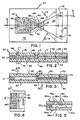
- Fig. 2 is a section view, taken generally along the line II-II of Fig. 1, showing liquid in the first zone of the vessel ;
- Fig. 3 is a section view, similar to that of Fig. 2, showing the liquid in the second zone of the vessel ;
- Fig. 4 is a fragmentary plan view of a device similar to that of Fig. 1, but which is a comparative example rather than an embodiment of the present invention ;
- Figs. 5, 6 and 7 are fragmentary section views similar to the view shown in Fig. 3, but illustrating alternative embodiments of the present invention ;
- Figs. 8 and 9 are section views similar to that of Fig. 3, illustrating still further embodiments of the present invention ;
- Fig. 10 is a plan view, similar to that of Fig. 1, illustrating a further embodiment of the present invention particularly adapted for the detection or measurement of antibodies or antigens ;
- Fig.. 11 is a section view taken generally along the line XI-XI of Fig. 10 ;
- Figs. 12A and 12B are plan views of the device of Fig. 10, showing two stages in the use of the device ;
- Fig. 13 is a section view, similar to that of Fig. 2, illustrating an embodiment of the present invention particularly adapted for detection of an analyte of whole blood ;
- Fig. 14 is a plan view, similar to that of Fig. 12A, illustrating a three-zone embodiment of the present invention ; and
- Fig. 15 is a section view taken generally along the line XV-XV of Fig. 14.
- The present invention is described hereinafter with respect to the measurement or detection of analytes of biological liquids such as serum, plasma or whole blood. Liquids such as industrial liquids can also be analyzed using the vessel of the present invention. In addition, the vessel can be used to interact a liquid with a reagent for many other purposes.
- In Figs. 1 and 2, there is shown a
reaction vessel 20 comprising afirst zone 22 and asecond zone 24 adapted to receive liquid flow fromfirst zone 22.Zones passageway 60 having a meniscus control means therein which will be explained in more detail hereinafter. Vessel 20 comprises asupport member 44 and acover member 42 superposed overmember 44 and separated therefrom by a spacer member 30 (Fig. 2).Members zones members spacer member 30 by any conventional means, for example a water-insoluble adhesive. - Within
zones members liquid transport surfaces spacer member 30 providessidewall surfaces 32, 34, andend wall surfaces 36, 38 (Fig. 1). The location ofsidewall surfaces 32, 34, andend wall surfaces cover member 42 was transparent.Surfaces 26 and 28 (Fig. 2) are spaced apart a distance h inzone 22, and a distance h' inzone 24, both distances being selected to provide capillary flow of liquid. To ensure capillary flow of liquids, such as whole blood or blood serum, distance h should not exceed about 1 mm. To complete the transfer of all the liquid intosecond zone 24 once flow throughpassageway 60 has started and to retain liquid inzone 24, distance h' is preferably less than distance h. Specifically, a reduction in h' relative to h of at least 25 % is useful to induce substantially complete liquid transfer tozone 24 within a desirable length of time for most analyses. Most preferably, h is 125 µm, or less, to minimize the amount of liquid required for a reaction within the vessel, and h' is 94 µm or less. The selection of distance h' to be significantly less than h requires that the areas ofsurfaces second zone 24 be enlarged, relative to the areas ofsurfaces first zone 22, to ensure that all of the liquid ofzone 22 will be accommodated inzone 24. - Additional zones (not shown) not having capillary spacing and therefore not adapted to receive liquid flow can be connected to
second zone 24, for example adjacent toend wall surface 38. - To permit introduction of liquid into
first zone 22, inlet means in the form of anaperture 46 is provided incover member 42. A predetermined volume of liquid is deposited ataperture 46, preferably in drop form. The size ofaperture 46 is selected to ensure that the volume of liquid introduced will contact bothsurfaces first zone 22. If 10 >1 of liquid is the amount to be introduced for purposes of an intended test,aperture 46 is preferably about 1.0 mm to about 5.0 mm in diameter. Alternatively,aperture 46 is shaped to have cornered sidewalls (not shown), for example such that the shape in cross-section is hexagonal, to ensure more positive movement of the liquid into theaperture 46. To ensure the proper shape of the liquid wave front, or meniscus, and to prevent air entrapment,aperture 46 is preferably located at a point closer to endwall surface 36 than to sidewallsurfaces 32 or 34, Fig. 1. Most preferably, it is located on the centre line, designated 48, between sidewall surfaces 32 and 34. - The reagent (not shown) with which the liquid is to interact in
zone 22 is preferably coated, or otherwise bonded, such as by a chemical bond, onto any one of the exposed surfaces ofzone 22, e. g., surfaces 26, 28, 32, 34 or 36. The reagent can be soluble or insoluble in the liquid to be reacted. - To permit air to be expelled from
zones apertures 50 are provided, preferably throughcover member 42 in the vicinity ofzone 24. Most preferably, oneaperture 50 is located adjacent to the intersection formed bysidewall surface 32 withend wall surface 38, and asecond aperture 50 is located adjacent the intersection formed by sidewall surface 34 withend wall surface 38. Such locations ofapertures 50 permit full capillary flow inzone 24 with a minimum amount of resistance. - In accordance with an important aspect of the invention, a meniscus control means is provided in
passageway 60 to control the liquid by stopping it from flowing fromzone 22 tozone 24. As shown in Figs. 1 and 2, the meniscus control means inpassageway 60 includes sidewall surfaces 32, 34, which converge in the direction of fluid flow, and sharply definedopposed edges 62, located between thezones zone 22, measured fromaperture 46 to edges 62. - It is not certain what interaction between the liquid meniscus, designated 68 in Fig. 1, and the sidewall surfaces 32, 34, creates the phenomenon of meniscus stoppage. Tests have shown that the use of gradually, rather than abruptly, converging sidewall surfaces is preferred, together with
edges 62 being limited to a radius of curvature no greater than about 0.02 cm. In this construction, edges 62 act as an energy barrier to capillary flow of liquid and specifically to advancement ofmeniscus 68. Flow of gas is not blocked, however, sincepassageway 60 is free of material that would block gas flow. - The convergence of sidewall surfaces 32 and 34 in
zone 22 need not be at a constant rate. Alternatively, sidewall surfaces 32 and 34 can converge at an increasing rate as flow proceeds toward edges 62. In one embodiment of this alternative (shown as dashed lines forzone 22 in Fig. 1), the sidewall surfaces 32, 34, are concave and provide an increased volume forzone 22. - It is desirable that liquid flow stop at
edges 62 when most, and preferably substantially all of the liquid, is withinzone 22. That is, the volume of the liquid is selected to be consistent with the volume ofzone 22. Only a negligible amount, if any (shown as portion L in Fig. 2) should project out of the reaction vessel. In, for example, immunoassay uses of the vessel, it is desirable that all of the predictable volume of liquid react inzone 22 with an immuno-reagent. For this reason, at least for tests involving constant liquid volumes, one of themembers zones zone vessel 20, and with atmospheric pressure on both sides of the member, a free-span deflection, hereinafter « sag », that does not exceed about 0.025 mm. Inzone 22, ifmember 42 has any appreciable sag, one or both of the following could occur: The sagging portion could act as a « meniscus control means ", prematurely stopping the meniscus beforepassageway 60 is reached. The sagging portion could also cause air entrapment in the vicinity thereof. In either case, the entire volume of added liquid would not flow intozone 22, and the interaction with the reagent of that zone would not occur to the desired extent. -
Cover member 42 is preferably rigid in the area ofzone 24 because sagging portions could again cause air entrapment. Such air entrapment could prevent transfer of all of the liquid from thefirst zone 22 to thesecond zone 24. - Although it is not critical to an understanding of the invention, it is believed that the shape of the
meniscus 68 as it approaches theedges 62 is at least partially responsible for the stoppage of themeniscus 68. The shape ofmeniscus 68 at several positions inpassageway 60 is shown by dashed lines 68' in Fig. 1. Ifmeniscus 68 is angled to the sidewall surfaces 32, 34, ofpassageway 60, as shown by lines 68', it does stop atedges 62, in the absence of extemally-generated pressures. - In contrast to the
vessel 20 shown in Fig. 1, a comparative example is shown in Fig. 4 in which awall 67 extends generally perpendicular to asidewall surface 32"; such an arrangement will not stop the capillary liquid flow. In the comparative example, anaperture 69 has a spacing D comparable to distance « d inpassageway 60 ofvessel 20. Instead of being stopped, flow of liquid continues throughaperture 69 at a retarded rate, as is described in the aforementioned European Patent Application No. 80302501.4 (Publication No. 0 023 156). In the example shown in Fig. 4, themeniscus 68" tends to have a shape, in the vicinity ofaperture 69, that is roughly parallel towall 67. - With reference to Fig. 1, sidewall surfaces 32 and 34 preferably extend from
edges 62 intozone 24 with a configuration that aids in the emptying of all the liquid intozone 24 once flow starts past edges 62. (See Fig. 3.) The sidewall surfaces 32, 34 preferably diverge fromedges 62 intozone 24 with a constantly increasing spacing S 2 (Fig. 1) or at an increasing rate (shown in dashed lines as convexly curved walls having a radius R). - The pressure AP (Fig. 3) needed to push the
liquid meniscus 68past edges 62 is an inverse function of the distance d. Accordingly, distance d is selected to provide sufficient stoppage of themeniscus 68 without requiring the use of excessive external pressures. A preferred value of d is about 0.04 cm. If distance h' is about 0.03 cm, the distance fromaperture 46 toedges 62 is about 0.9 cm, and d is about 0.04 cm, the pulse of pressure necessary to push aserum meniscus 68 past theedges 62 is about 80 Pa. Lesser values of d will require greater pressures to overcome the stoppage of flow at edges 62. - « Extemaiiy-generated pressure,,, as used herein, refers to any external pressure applied to the liquid, including a pressure applied to the liquid through the
aperture 46, a vacuum applied to the liquid, or a pressure on the liquid resulting from a centrifugal force applied to thereaction vessel 20. - A further important aspect of this invention is the increased capillary attraction provided by the reduced distance h' of second zone 24 (Fig. 2) ; it is this increased capillary attraction that causes completion of the transfer of liquid from
zone 22 tozone 24, rather than the displaced air created by the extemally-generated pressure. The advantage is that the capillary attraction is effective to provide complete transfer of liquid tosecond zone 24, even if the volume of liquid infirst zone 22 deviates slightly from the expected volume. The use of pressure displacement to displace a given volume of liquid equal to the displaced air volume would not be readily adjustable for such liquid volume deviations. Therefore, the AP pressure applied to push theliquid meniscus 68 intozone 24 is only an impulse, the duration of which is by itself insufficient to transfer all the liquid. A duration of between about 1 and about 10 ms is sufficient in many cases to push themeniscus 68 intozone 24. - To minimize shear stresses as liquid is forced to flow
past edges 62, the length 1 of edges 62 (Fig. 2) is minimized. Specifically, by providingsharp edges 62 with a negligible length in the direction of fluid flow, preferably no greater than 0.03 cm, the shear stresses that occur when liquid flowspast edges 62 are minimized. The relatively low shear stresses permit the processing of whole blood, as is described hereinafter. - The preferred gas used to form the pulse of pressure AP is air. It will be appreciated that other gases are also useful, most preferably those that are inert relative to the liquid and the reagents used.
- Although an immiscible liquid is useful also as a medium for delivering the pulse of pressure, gas is the preferred medium inasmuch as an immiscible liquid could move ahead of the reaction liquid and prevent complete transfer of the desired liquid to the
second zone 24. - The behaviour of liquid introduced into
zone 22 ataperture 46 will be apparent from the above description. That is, distance h is such that liquid introduced intozone 22 will flow within and through thezone 22, between the opposed liquid transport surfaces 26 and 28, by means of capillary attraction. A characteristic ofpassageway 60 is that the advancingliquid meniscus 68 stops atedge 62 even in those instances in which minor amounts L of liquid remain above aperture 46 (Fig. 2). The liquid remains temporarily stopped atedges 62 while any gas generated inzone 22 is free to flow intozone 24. Thereafter, if an externally-generated pressure pulse AP of air (Fig. 3) is applied to the liquid inzone 22, the energy barrier ofedges 62 is overcome, and the liquid ofzone 22 flows, in the direction ofarrows 66, intozone 24. As noted above, the applied pressure is preferably insufficient to cause, absent other forces, a completion of the transfer of liquid fromzone 22 tozone 24. - In accord with well-known principles of capillarity, the smaller spacing (distance h) ensures that the liquid will preferentially flow into
zone 24, emptyingzone 22, and further, that the liquid will not return tozone 22. Air is pushed out throughapertures 50 ahead of the advancingmeniscus 68. Themeniscus 68 stops when it reachesapertures 50, as shown at 70 (Fig. 3). Additional processing can then take place inzone 24; for example, a reaction with additional reagents, or a measurement of analyte in the liquid by an appropriate scan (arrow 72) using electromagnetic radiation that passes through eithersupport member 44, as shown, or covermember 42 if exposed from above (not shown). If the direction of scan is as indicated by arrow 72,member 44 is preferably transparent, at least in the area ofzone 24. Ifzone 22 is scanned also, theentire member 44 is preferably transparent. - Measurements conducted in the
second zone 24 are selected to be compatible with the reagent and the interaction provided in thefirst zone 22. Useful examples of measurements include radiometric detection of a change in the liquid. Specifically, a photometer (not shown) or a fluorimeter (not shown) can be used to detect, respectively, the production of a dye density or a fluorescence. Also, measurements using the detection of radioactive labels are possible withvessel 20. - Specific useful materials for
members cover member 42. In addition, a flexible material such as a 25 µm polyethylene sheet is useful to provide theliquid transport surface 26 of thecover member 42 ; if used, the polyethylene sheet can be laminated to a sheet of one of the rigid materials noted above. - As an alternative to the use of a reduced value of h', liquid can be preferentially and permanently emptied from
zone 22 intozone 24 by the use of a surfactant, soluble in the liquid, that is coated on either or both ofsurfaces surfaces zones surfaces surfaces zone 22 can be filled. However, the surfactant immediately dissolves from thesurfaces zone 22 when wetted. Therefore, after the liquid flows intozone 24, a thin film residue of liquid apparently forms and evaporates, and surfaces 26 and 28 ofzone 22 revert back to being essentially non-wettable. Thus, the liquid cannot return tozone 22. In such an embodiment, any distance h' effective to ensure capillary flow intozone 24, such as 1 mm or less, is useful regardless of its relationship to distance h ofzone 22. That is, the trailing edge (not shown) ofliquid exiting zone 22 «sees a surface condition that is essentially non-wettable. In contrast, the advancingmeniscus 68 readily wets the surfactant- coatedsurfaces zone 22 intozone 24. Furthermore, the hydrophobic nature of thesurfaces zone 22 is a sufficient energy barrier to return flow. - The previously-discussed embodiments are based on the assumption that, once the liquid has moved into the
second zone 24, no significant amount of the liquid should remain in or flow back to thefirst zone 22, such as by a return flow past edges 62. However, in some instances it is desirable for liquid to remain in or return to thefirst zone 22; for example if thefirst zone 22 of thereaction vessel 20 is to be used to carry out an additional reaction on reaction products produced in thesecond zone 24. For this embodiment (not shown), distances h and h' between the opposed transport surfaces of the twozones second zone 24 where it can react with a reagent in that zone. An additional reagent is immobilized in thefirst zone 22, the reagent being selected to react only with the reaction products produced by the reagent of thesecond zone 24. As each reaction takes place in its respective zone, a concentration gradient is created that induces diffusion of the necessary ingredient or reaction product to the zone where that reaction takes place. - In Fig 5, there is shown an alternative embodiment of the present invention in which parts similar to those previously described bear the same reference numeral to which the distinguishing suffix « a has been attached. Thus, a vessel 20a comprises a cover member 42a, support member 44a, and spacer member 30a defining a first zone 22a, a second zone (not shown), and a meniscus control means as described above. Transport surface 26a, however, is provided with
sawtooth ridges 80 spaced apart a regular distance. Preferably theridges 80 are mutually parallel and extend perpendicularly to a bisector line (not shown) between the sidewalls (not shown). If surface 28a also has ridges (not shown), the ridges preferably extend at a positive angle to theridges 80 of surface 26a in the manner taught by European Patent Application No. 79302338.3 (Publication No. 0014797). - An alternative embodiment of the present invention is shown in Fig. 6, in which parts similar to those previously described bear the same reference numeral to which the distinguishing suffix « b is applied. In Fig. 6, a vessel 20b comprises a
cover member 42b and asupport member 44b,member 42b having an inlet aperture 46b for receiving liquid into azone 22b. However, unlike previous embodiments, spacing H adjacent the aperture 46b is non-capillary, surfaces 26b and 28b being shaped to gradually converge to be spaced a capillary spacing h in the portion ofzone 22b contiguous with the passageway (not shown). No sharp edges are present adjacent aperture 46b to create a barrier to flow. In this embodiment, liquid must be delivered tozone 22b with an initial pressure sufficient to move the liquid into that portion ofzone 22b wherein the spacing betweenmembers End wall surface 36b is preferably sloped in this embodiment, to deflect incoming liquid to ensure that the liquid continues to advance to the point where capillary flow starts. The embodiment shown in Fig. 6 also demonstrates that the spacing betweenmembers shoulder 30b, can be an integral part ofmember 44b, as shown, or ofmember 42b. - In Fig. 7, there is shown an alternative embodiment of the present invention in which parts similar to those previously described bear the same reference numeral to which the distinguishing suffix « c » is applied. Thus, vessel 20c comprises a
cover member 42c and a support member 44c that respectively providetransport surface 26c andtransport surface 28c;members 42c and 44c are preferably formed from hydrophobic materials coated with a water-soluble surfactant as described above. Afirst zone 22c and asecond zone 24c are separated by a passageway 60c which is provided with a meniscus control means, as described in a previous embodiment. However, in the embodiment shown in Fig. 7, the meniscus control means includes sharply definededges 62c formed in the transport.surfaces sidewall surface 32c and an opposite sidewall surface (not shown). The shape oftransport surfaces meniscus 68c, as it moves through passageway 60c, extends generally perpendicularly (dashed lines 90) to thesurfaces meniscus 68c apparently ensures that theedges 62c act as an energy barrier to further liquid flow. Most preferably, surfaces 26c, 28c, are shaped so that distance « h" between them is reduced at an increasing rate, in the vicinity of passageway 60c, to create opposed concavities immediately adjacent theedges 62c. As in previous embodiments, the length I ofedges 62c in the direction of flow preferably does not exceed 0.03 cm. In this embodiment, the spacing betweensidewall surface 32c and the opposite sidewall surface (not shown) is of no consequence to the stoppage of themeniscus 68c ; such spacing can be selected to be constant or variable, as desired. - Preferably,
zone 24c includes opposed surfaces 92 (here portions ofsurfaces zone 24c from passageway 60c at a separation distance that increases at a constant or at an increasing rate. Such a rate of separation helps to ensure that once theliquid meniscus 68c moves intozone 24c, all the liquid will flow intozone 24c. - Alternative embodiments are shown in Figs. 8 and 9 in which parts similar to those previously described bear the same reference numeral to which the distinguishing suffices « d » and « e », respectively, are appended. Thus, a
vessel 20d and avessel 20e are constructed in generally the same manner as thevessel 20 of Fig. 1, and include opposedliquid transport surfaces second zones channel 100 intransport surface 26d having a depth h2 and a width w2 that are sufficient to create an energy barrier to liquid flow, and thus, to stop flow. Specifically, the energy barrier comprises thesharp edge 101 created insurface 26d by the sudden depth h2 ofchannel 100. In order to be effective, thechannel 100 extends the full width between the zones. Most preferably, the depth h2 ofchannel 100 is at least 0.02 mm greater than the spacing hd betweensurfaces channel 100 is greater than or equal to hd. As in the embodiment of Fig. 1, distance hd' of zone 24d is significantly less than distance hd of zone 22d, and the total volumes of the two zones are adjusted to be generally equal. The radius of curvature ofedge 101 preferably does not exceed about 0.02 cm. - In the embodiment of Fig. 9, the meniscus control means comprises a pair of
opposed channels 100' and 100", with a depth h3 and h4, respectively, and a width w3. To create the energy barrier to capillary flow, both edges 101e are sharp as before and the combined depth (h3 + h4) is preferably at least 0.015 mm greater than the distance he. Width w3 need not have the same relationship to he as w2 has to hd in the embodiment of Fig. 8. Preferably w3 is at least 25 µm. Distance he' is at least 25 % less than he. A total depth (he + h3 + h4) that is greater than a capillary spacing is also useful. The externally-generated pressure is selected to be large enough to movemeniscus 68e into contact withzone 24e. A pressure of at least 80 Pa is useful forchannels 100' and 100" having depths such that h3 + h4 + he total about 0.415 mm, and a common width w3 equalling 25 µm. - The reaction vessels 20-20e described above are useful to provide a variety of interactions in the first zone 22-22e between a reagent and material of the liquid, followed by analysis in the second zone 24-24e. As used herein, a « reagent means any substance that is interactive with a material, such as an analyte, of the liquid, or a decomposition or reaction product of that material. « Interaction and » interactive refer to chemical reactions, catalytic activity such as enzymatic reactions, immunological reactions, or any other form of chemical or physical interaction that can result in the production of a useful result in the second zone. Preferred are those interactions that permit analysis of the material of the liquid. Highly preferred are binding reactions in which a reagent immobilized in the first zone 22-22e binds to at least a portion of the material of the liquid, thus retaining that bound portion in the first zone 22-22e. This binding reaction occurs whether the materials to be bound are labelled or unlabelled. If a vessel is to be used as an immunoassay device, as described hereinafter, both labelled analog and unlabelled analyte comprise the material that binds, in a competing fashion, to the reagent. If a vessel is to be used as a test device for whole blood, also as described hereafter, the materials that bind are the cells of whole blood, which need not be labelled for purposes of the test.
- Preferably the reagent is immobilized on one or both of the sidewall surfaces, or the opposed transport surfaces, of the first zone 22-22e of the vessel 20-20e of the present invention. Altematively, and particularly in those instances in which a relatively high volume of material is to interact with the immobilized reagent, the reagent is immobilized on filler such as beads as described in European Patent Application No. 79303004.0 (Publication No. 0 013 156). The beads (not shown) in turn are disposed in the first zone 22-22e and secured in place, for example by the use of a water-insoluble adhesive of the type described in the aforesaid European Patent Application No. 79303004.0 (Publication No. 0 013 156). In yet another embodiment (not shown) the beads are loosely disposed in the first zone, having a size that prevents them from passing through a passageway between the first zone and an adjacent zone; in this embodiment, distance d » is substantially less than distance «h».
- As used herein, c immobilized » refers to a condition of immovable adherence created by any mechanism, such as chemical bonding, that is sufficient to withstand the pressures and stresses generated within a zone during use of a vessel or test device. A reagent is immobilized to one of the surfaces of a zone, or to inert fillers in the zone, if that reagent is bonded or adsorbed directly thereto, or if it is bonded via an intermediate, water-insoluble material that is itself secured to a zone.
- Highly preferred reagents include those which produce immune-reactions, such as antibodies or antigens, hereinafter « immunogens ». The material of the liquid in such a case is the corresponding immunogen, that is, the antigen or antibody, respectively. Any immuno-reaction is detectable, using the present invention, by the procedure hereinafter described. Immunological reagents, hereinafter «immunogen reagents », are preferably immobilized by being adsorbed or covalently bonded by any conventional procedure to any of the surfaces of a first zone, or to beads that are secured to a first zone.
- One example of a useful procedure for covalently bonding an immunogen reagent is as follows : A polyacrylamide is selected to which the immunogen reagent is to be secured. This is either the material of a surface of a zone, or polyacrylamide beads adhered to a surface by a water-insoluble adhesive. The polyacrylamide in turn is partially hydrolyzed or hydrazinolyzed to permit covalent bonding by the antibodies. Details are described, for example, in US-A-3 853 987.
- Indirect covalent bonding is also useful wherein a coupling agent is used having groups that will covalently bond with both the immunogen reagent and a surface of a zone (or beads secured to the zone). For example, covalent bonding of an immunogen reagent to ceramic beads is possible using the intermediate coupling agents described in US-A-3 652 761.
- The selection of an immunogen as the reagent permits immunoassays to be conducted using the present invention. In Figs. 10-128, there is disclosed an alternative embodiment which is adapted to such a use. Parts similar to those previously described bear the same reference numeral to which the distinguishing suffix « f is applied. Thus, a vessel 20f is a test device comprising first and
second zones cover member 42f, support member 44f andspacer member 30f (Fig. 11). The twozones member 42f permits liquid introduction andapertures 50f permit air venting. To minimize air entrapment, sidewall surfaces 32f and 34f are joined at an angle beta (j3), and aperture 46f is on the bisector of angle β (Fig. 10). Angle β is preferably between about 7 and 75 degrees, and most preferably, 60 degrees. Sidewall surfaces 32f and 34f are curved toward each other in the area of passageway 60f to prevent the advancing wavefront from encountering edge discontinuities before encountering edges 63f. As edges 62f are neared, surfaces 32f and 34f converge at an increasing rate, consistent with the absence of edge discontinuities other than edge 62f. If angle β is about 60 degrees, then the angle of convergence gamma (y) (Fig. 10) is preferably about 120 degrees. - Most preferably, an immunogen reagent for a particular complementary immunogen is immobilized in the
first zone 22f, in the form, for example, of a coating 110f bonded tosurface 28f ofzone 22f (Fig. 11). Preferably, surface 26f bears a water-soluble surfactant (not shown) as discussed for previous embodiments. A known amount of the analog having an appropriate label is added tozone 22f either as an additional pre-applied reagent or as a liquid added with, to, or after the unknown sample. It will be appreciated that care is taken not to admix the analog and the immunogen reagent before adding the immunogen of the liquid to be assayed. The label is any detectable species, for example, an enzyme, a fluorescent species, or a radioactive species, chemically or physically linked (such as by adsorption) to the antigen or antibody. For example, a fluorescent species such as fluorescein is covalently bonded to an antigen. In a preferred embodiment, a polymeric latex bead is « loaded with a fluorescent rare earth chelate, preferably a europium or terbium chelate. The resultant rare earth chelate-loaded latex bead is employed as a fluorescent label to which the analog of choice is physically adsorbed or covalently bonded. These latex polymer beads preferably have an average diameter of from about 0.01 to about 0.2 µm and are « loaded with up to about 7.5 weight percent of the rare earth chelate. Because of the large number of rare earth chelate molecules which can be loaded into a single latex bead, the resultant label is highly fluorescent and provides immuno-fluorescence exhibiting excellent sensitivity. A highly-preferred analog is one employing a fluorescent, rare earth chelate-loaded polymeric latex bead as described in European Patent Application No. 78300913.7 (Publication No. 0 002 963). - While the liquid is retained in the first zone as shown by the location of
meniscus 68f (Fig. 12a) the analog and the immunogen to be assayed compete for binding to the immunogen reagent which is immobilized in thefirst zone 22f of the vessel. After an appropriate length of time, for example, 5 to 15 minutes, a pulse of pressure such as 80 Pa is applied to force the liquid to empty from thefirst zone 22f into thesecond zone 24f (Fig. 12b) carrying immunogen and analog that have not become bound to the immunogen reagent. Useful methods of measurement to determine the concentration of immunogen include: (A) detecting the unbound analog which has flowed into the second zone, and/or (B) detecting the analog which remains bound to the immobilized immunogen reagent in the first zone. In either method, the amount of immunogen in the liquid sample is determined based on the detected concentration of analog in accordance with conventional immunological techniques. Such techniques are set forth in European Patent Application No. 79303004.0 (Publication No. 0013156). - It has been determined that the ionic bond formed in an immuno-reaction is sufficient to withstand the shear stress generated by the pulse of pressure used to force plasma, for example, having a viscosity of 2.4 mPa.s, to flow from
zone 22f intozone 24f through passageway 60f. That is, under less than the best conditions, the shear force likely to occur can be shown to be about 2 x 10-14 N/molecule. The energy bond strength can be shown to be about 10-10 N/molecule, more than . enough to resist the stress. - An avantage of vessel 20f is that the concentration determined by the measurement made in
zone 24f of free analog, can be checked by measuring the bound analog inzone 22f. - The present invention is useful in performing analyses of whole blood. In such an application, the immobilized reagent is selected to be a red cell-agglutinating reagent. Such a reagent attracts or binds substantially all the red blood cells of whole blood added to the device, leaving only the plasma free to flow into a second zone of a reaction vessel, such as vessels 20-20f, when an externally-generated pulse of pressure is delivered to the liquid in the manner described above. The necessary reagents for analyzing the analyte of the plasma are contained in the second zone.
- Useful examples of such reagents for immobilizing the red cells include agglutinating reagents such as positively-charged polymers, e. g., polyb- rene ; lectins ; high molecular weight dextrans ; and phytohemagglutinin as described in US-A-3 146 163, and US-A-3 902 964. The last-noted materials are proteinaceous, and as such are subject to bonding to appropriate surfaces, such as polyacrylamide, by the procedures described above. Thus, agglutinating agents are readily immobilized within a reaction vessel and/or to beads secured in the vessel.
- In Fig. 13, there is disclosed an alternative embodiment useful as a test device for the measurement of an analyte of whole blood. Parts similar to those previously described bear the same reference numeral to which the distinguishing suffix « g is applied. Thus, a vessel 20g comprises cover and
support members members first zone 22g and asecond zone 24g with apassageway 60g betweenzones zone 22g throughaperture 46g, andapertures 50g are provided for the venting of air fromzone 24g. Also, as in the device of Fig. 11, areagent coating 110g is applied to at least one of themembers forming zone 22g directly, or to beads (not shown) adhered within the zone.Surface 26g of bothzones members zone 22g. In this case, the reagent is an agglutinating agent such as phytohemagglutinin, immobilized as described above. - Altematively, vessel 20g is useful if the vent apertures are formed in spacer member 30g, as shown by the dashed
lines 50g' of Fig. 13. Preferably,such apertures 50g' are formed by notching the top of spacer member 30g. - To permit analysis of the plasma as it enters
zone 24g in response to a pulse of pressure, ananalyte detection element 120g is provided in or adjacent tomember 44g inzone 24g. Preferably the detection element comprises one or more detection reagent layers 122g having a variety of binder compositions and a variety of detection reagents. For example, gelatin, cellulose acetate, polyvinyl alcohol, agarose and the like are useful binders, the degree of hydrophilicity of the layer being dependent upon the material selected. - Additional layers, disposed above
layer 122g, are useful to provide a variety of chemistries or functions. If used, these additional layers provide additional detection reagents, or filtering, registration and/or mordanting functions, such as are described in US-A-4 042 335. - As used herein, «detection reagent means a material that is capable of interaction with an analyte, a precursor of an analyte, a decomposition product of an analyte, or an intermediate of an analyte, to ultimately produce a detectable response. Useful detection elements in many instances include a first detection reagent that produces from the analyte an intermediate or a decomposition product, and a second detection reagent, labelled « indicator because of its function, that is responsive to the intermediate or decomposition product to produce said change. Useful detection reagents also include preformed, radiometrically detectable species that are caused by the analyte of choice to move out of a radiometrically-opaque portion or layer of the detection element and into a radiometrically-transparent portion or layer, such as a registration layer which can be
layer 122g in contact withmember 44g. - The noted interaction between a detection reagent and the analyte therefore includes chemical reactions, catalytic activity as in the formation of an enzyme-substrate complex, or any other form of chemical or physical interaction, including physical displacement, that can produce ultimately a detectable response in the test element. The assay method is designed to produce a response signal that is predictably related to the amount of analyte that is present.
- The preferred detection element is designed to measure radiometric responses, produced by impinging electromagnetic energy on the element. As is well known, radiometric detection includes both colorimetric and fluorimetric detection, the method used depending upon the detection reagents selected as the indicator.
- The
detection element 120g is adaptive to a variety of different analytes. Preferably, the assays are all oxygen-independent, as the flow of liquid into thezone 24g tends to seal offdetection element 120g from any additional oxygen. Typical analytes which can be tested include total protein, bilirubin and the like. Useful detection reagents and binder or vehicle compositions for, e. g.,layer 122g and any additional layers of the element include those described in US-A-4 132 528, and US-A-4069016 or US-A-4069017.Detection element 120g is also useful to test for other analytes. - The method of using vessel 20g will be apparent from the preceding discussion. A quantity of whole blood, for example, a drop, is added to
zone 22g viaaperture 46g, and the meniscus flows up to edges 62g ofpassageway 60g, where it stops.Coating 110g comprises a red cellaggluti- nating reagent which immobilizes the red cells while the liquid remains inzone 22g. After an appropriate length of time, such as 10 minutes, the plasma is separable from the cells by applying an impulse of pressure, such as a pressure of about 80 Pa, toaperture 46g. The plasma flows intozone 24g and intodetection element 120g. After an incubation period of up to about five to ten minutes, a radiometric signal is projected ontoelement 120g which is detected by a suitably calibrated radiometer (not shown). - Another alternative embodiment of the present invention is shown in Figs. 14 and 15. Parts similar to those previously described bear the same reference numeral to which the distinguishing suffix « h » is added. Thus, a
vessel 20h comprises cover andsupport members spacer member 30h.Aperture 46h inmember 42h permits introduction of liquid to afirst zone 22h having acoating 110h on asurface 28h thereof (Fig. 15).Coating 110h comprises a cell-agglutinating reagent bonded tosurface 28h, as described for the embodiment shown in Fig. 13.Surface 26h is preferably coated with a water-soluble surfactant (not shown), andmembers Passageway 60h is provided with a meniscus control means which includes opposed, sharply- definedsidewall edges 62h (Fig. 15); the meniscus control means serves to confine the whole blood withinzone 22h to allow the red blood cells to become bound. - In addition to
first zone 22h,vessel 20h comprisessecond zone 160 and athird analysis zone 24h disposed downstream fromzone 22h. Each of thezones edges 62h inpassageway 60h andopposed edges 163 in passageway 162 (Fig. 15).Edges 163 are located on thetransport surfaces sidewall surfaces detection element 120h (Fig. 14). -
Zone 160 preferably includes acoating 164 onsurface 28h (Fig. 15) of a detection reagent in addition to those present indetection element 120h located inzone 24h. As shown,detection element 120h is a multi-layered element the layers of which are stacked in the direction of the flow of liquid intozone 24h. In a preferred form,detection element 120h comprises atleast layer 122h, and optionally, adetection reagent layer 126 and abarrier composition layer 124. The barrier composition is uniformly permeable to a gas such as NH3, but is substantially impermeable, over the time of the test, to interferents such as are carried by water. Because of this arrangement, avent aperture 50h is preferably located inspacer member 30h. - A preferred use of
vessel 20h is as a test device for plasma ammonia alone, or for plasma ammonia followed by plasma creatinine. Coating 164, for these uses, comprises a buffer selected to maintain a pH of about 9.0 in the plasma to release dissolved ammonia. A preferred buffer is a mixture of tris buffer, comprising tris-(hyd- roxymethylaminomethane), and KH2P04.Layer 122h ofelement 120h comprises an indicator responsive to ammonia that changes colour in proportion to the amount of NH3 gas that flows intolayer 122h fromzone 160 while the plasma is being retained inzone 160. For example, bromophenol blue is useful as the indicator. - Alternatively,
vessel 20h further includes a detection reagent, preferably inlayer 126, that decomposes creatinine into NH3 gas, and the described barrier composition, preferably inlayer 124, that allows the NH3 but not the liquid of the plasma to permeate. Useful compositions forlayers layer 122h, are described in US-A4276 377. - The above-described alternative construction of
vessel 20h anddetection element 120h is used first to test for plasma ammonia, and then, optionally, to test for plasma creatinine. After the plasma is forced intozone 160, coating 164 serves to release plasma ammonia as NH3 gas which flows intozone 24h while the plasma is stopped. at edges 162. The NH3 permeatesindicator layer 122h ofdetection element 120h to produce a detectable colour change. After the colour change, which is proportional to the plasma ammonia, is detected, the plasma is analyzed for creatinine content. For the creatinine test, a second impulse of air pressure is applied ataperture 46h to push the liquid meniscus pastedges 162, intozone 24h and then intodetection element 120h. The additional NH3 generated from the decomposition of creatinine is detectable by the same indicator used for the plasma ammonia. To usevessel 20h as a test device only for plasma ammonia, the second impulse of pressure is simply omitted. - Yet another alternative embodiment of the invention (not shown) comprises the device of Fig. 15 wherein
zone 22h is omitted and a previously obtained plasma is placed via an inlet aperture, similar toaperture 46h, directly intozone 160. The procedure for the sequential detection of plasma ammonia and/or creatinine is as described above.
Claims (29)
characterized by retaining said liquid with the meniscus forming the leading edge of the capillary flow contiguous to said passageway while a reagent in said first zone interacts with said material,
Applications Claiming Priority (2)
| Application Number | Priority Date | Filing Date | Title |
|---|---|---|---|
| US229038 | 1981-01-28 | ||
| US06/229,038 US4426451A (en) | 1981-01-28 | 1981-01-28 | Multi-zoned reaction vessel having pressure-actuatable control means between zones |
Publications (4)
| Publication Number | Publication Date |
|---|---|
| EP0057110A2 EP0057110A2 (en) | 1982-08-04 |
| EP0057110A3 EP0057110A3 (en) | 1982-08-18 |
| EP0057110B1 EP0057110B1 (en) | 1985-04-17 |
| EP0057110B2 true EP0057110B2 (en) | 1990-01-03 |
Family
ID=22859590
Family Applications (1)
| Application Number | Title | Priority Date | Filing Date |
|---|---|---|---|
| EP82300427A Expired - Lifetime EP0057110B2 (en) | 1981-01-28 | 1982-01-27 | Reaction vessel and method for combining liquids and reagents |
Country Status (5)
| Country | Link |
|---|---|
| US (1) | US4426451A (en) |
| EP (1) | EP0057110B2 (en) |
| JP (1) | JPS57156028A (en) |
| CA (1) | CA1189431A (en) |
| DE (1) | DE3263066D1 (en) |
Cited By (16)
| Publication number | Priority date | Publication date | Assignee | Title |
|---|---|---|---|---|
| US7638023B2 (en) | 2002-09-26 | 2009-12-29 | Roche Diagnostics Operations, Inc. | Capillary biosensor analysis system |
| US7645421B2 (en) | 2003-06-20 | 2010-01-12 | Roche Diagnostics Operations, Inc. | System and method for coding information on a biosensor test strip |
| US7645373B2 (en) | 2003-06-20 | 2010-01-12 | Roche Diagnostic Operations, Inc. | System and method for coding information on a biosensor test strip |
| US7718439B2 (en) | 2003-06-20 | 2010-05-18 | Roche Diagnostics Operations, Inc. | System and method for coding information on a biosensor test strip |
| US7727467B2 (en) | 2003-06-20 | 2010-06-01 | Roche Diagnostics Operations, Inc. | Reagent stripe for test strip |
| US7977112B2 (en) | 2003-06-20 | 2011-07-12 | Roche Diagnostics Operations, Inc. | System and method for determining an abused sensor during analyte measurement |
| US8058077B2 (en) | 2003-06-20 | 2011-11-15 | Roche Diagnostics Operations, Inc. | Method for coding information on a biosensor test strip |
| US8071030B2 (en) | 2003-06-20 | 2011-12-06 | Roche Diagnostics Operations, Inc. | Test strip with flared sample receiving chamber |
| US8071384B2 (en) | 1997-12-22 | 2011-12-06 | Roche Diagnostics Operations, Inc. | Control and calibration solutions and methods for their use |
| US8092668B2 (en) | 2004-06-18 | 2012-01-10 | Roche Diagnostics Operations, Inc. | System and method for quality assurance of a biosensor test strip |
| US8206565B2 (en) | 2003-06-20 | 2012-06-26 | Roche Diagnostics Operation, Inc. | System and method for coding information on a biosensor test strip |
| US8298828B2 (en) | 2003-06-20 | 2012-10-30 | Roche Diagnostics Operations, Inc. | System and method for determining the concentration of an analyte in a sample fluid |
| US8404100B2 (en) | 2005-09-30 | 2013-03-26 | Bayer Healthcare Llc | Gated voltammetry |
| US8425757B2 (en) | 2005-07-20 | 2013-04-23 | Bayer Healthcare Llc | Gated amperometry |
| US8551308B2 (en) | 1999-10-04 | 2013-10-08 | Roche Diagnostics Operations, Inc. | Biosensor and method of making |
| US8663442B2 (en) | 2003-06-20 | 2014-03-04 | Roche Diagnostics Operations, Inc. | System and method for analyte measurement using dose sufficiency electrodes |
Families Citing this family (365)
| Publication number | Priority date | Publication date | Assignee | Title |
|---|---|---|---|---|
| US4663296A (en) * | 1980-05-05 | 1987-05-05 | Hoffmann-La Roche Inc. | Multicuvette rotor for analyzer |
| DE3134611A1 (en) * | 1981-09-01 | 1983-03-10 | Boehringer Mannheim Gmbh, 6800 Mannheim | METHOD FOR CARRYING OUT ANALYTICAL PROVISIONS AND MEANS SUITABLE FOR THIS |
| GB8306353D0 (en) * | 1983-03-08 | 1983-04-13 | Stuart J F B | Monitoring of drug levels |
| DE3441149A1 (en) * | 1984-11-10 | 1986-05-15 | Merck Patent Gmbh, 6100 Darmstadt | METHOD FOR SEVERAL BLOOD SEPARATION |
| EP0293519A1 (en) * | 1987-06-03 | 1988-12-07 | James F. Brown | Capillary flow control |
| US4676274A (en) * | 1985-02-28 | 1987-06-30 | Brown James F | Capillary flow control |
| DE3508427A1 (en) * | 1985-03-09 | 1986-09-11 | Merck Patent Gmbh, 6100 Darmstadt | AGENT AND METHOD FOR SEPARATING PLASMA OR SERUM FROM WHOLE BLOOD |
| JPS61278761A (en) * | 1985-06-04 | 1986-12-09 | Fuji Photo Film Co Ltd | Integral type multi-layered analyzing element for analyzing ammonia forming substrate |
| US4756884A (en) * | 1985-08-05 | 1988-07-12 | Biotrack, Inc. | Capillary flow device |
| US4761381A (en) * | 1985-09-18 | 1988-08-02 | Miles Inc. | Volume metering capillary gap device for applying a liquid sample onto a reactive surface |
| CA1292176C (en) * | 1985-09-18 | 1991-11-19 | Joel M. Blatt | Volume metering capillary gap device for applying a liquid sample onto a reactive surface |
| JPH0616045B2 (en) * | 1985-10-24 | 1994-03-02 | ヒユ−・ブイ・コツチンガム | Liquid particle reagent agglutination slide |
| FR2589239B1 (en) * | 1985-10-24 | 1989-10-20 | Cottingham Hugh | AGGLUTINOGRAPHIC REACTION CHAMBER |
| WO1987006003A1 (en) * | 1986-03-25 | 1987-10-08 | P B Diagnostic Systems, Inc. | Biological diagnostic device |
| US4906439A (en) * | 1986-03-25 | 1990-03-06 | Pb Diagnostic Systems, Inc. | Biological diagnostic device and method of use |
| JPS62273454A (en) * | 1986-04-28 | 1987-11-27 | アイ・シー・アイ・オーストラリヤ・リミテツド | Method and device for reaction |
| US5120504A (en) * | 1986-07-14 | 1992-06-09 | Hybritech Incorporated | Apparatus for immunoassays with vent chennels in the container side wall |
| US4753776A (en) * | 1986-10-29 | 1988-06-28 | Biotrack, Inc. | Blood separation device comprising a filter and a capillary flow pathway exiting the filter |
| US5135719A (en) * | 1986-10-29 | 1992-08-04 | Biotrack, Inc. | Blood separation device comprising a filter and a capillary flow pathway exiting the filter |
| DE3745131C2 (en) * | 1986-11-18 | 2000-06-29 | Hugh V Cottingham | Agglutinographic chamber for immunochemical liquid reagents |
| US4775515A (en) * | 1986-11-18 | 1988-10-04 | Cottingham Hugh V | Agglutinographic slide |
| DE3706718A1 (en) * | 1987-03-02 | 1988-09-15 | Boehringer Mannheim Gmbh | DEVICE FOR CARRYING OUT A HETEROGENEOUS REACTION |
| US4918025A (en) * | 1987-03-03 | 1990-04-17 | Pb Diagnostic Systems, Inc. | Self contained immunoassay element |
| US5047206A (en) * | 1987-03-11 | 1991-09-10 | Wayne State University | Reagent test strip |
| US4849340A (en) * | 1987-04-03 | 1989-07-18 | Cardiovascular Diagnostics, Inc. | Reaction system element and method for performing prothrombin time assay |
| DE3721237A1 (en) * | 1987-06-27 | 1989-01-05 | Boehringer Mannheim Gmbh | DIAGNOSTIC TEST CARRIER AND METHOD FOR THE PRODUCTION THEREOF |
| EP0305210B1 (en) * | 1987-08-27 | 1993-12-08 | Biotrack, Inc. | Apparatus and method for dilution and mixing of liquid samples |
| US5077017A (en) * | 1987-11-05 | 1991-12-31 | Biotrack, Inc. | Integrated serial dilution and mixing cartridge |
| US4810653A (en) * | 1987-11-23 | 1989-03-07 | Eastman Kodak Company | Cuvette with non-flexing thermally conductive wall |
| US5564419A (en) * | 1987-11-25 | 1996-10-15 | Radiometer A/S | Method of photometric in vitro determination of the content of oxygen in a blood sample |
| DK163194C (en) * | 1988-12-22 | 1992-06-22 | Radiometer As | METHOD OF PHOTOMETRIC IN VITRO DETERMINING A BLOOD GAS PARAMETER IN A BLOOD TEST |
| US5209904A (en) * | 1987-12-23 | 1993-05-11 | Abbott Laboratories | Agglutination reaction device utilizing selectively impregnated porous material |
| US4979402A (en) * | 1988-01-27 | 1990-12-25 | Ryan Will G | Aliquoting of serial liquid samples |
| US5200152A (en) * | 1988-03-28 | 1993-04-06 | Cytonix Corporation | Miniaturized biological assembly |
| US5503803A (en) * | 1988-03-28 | 1996-04-02 | Conception Technologies, Inc. | Miniaturized biological assembly |
| US5051237A (en) * | 1988-06-23 | 1991-09-24 | P B Diagnostic Systems, Inc. | Liquid transport system |
| US4957582A (en) * | 1989-03-16 | 1990-09-18 | Eastman Kodak Company | Capillary transport zone coated with adhesive |
| US5340539A (en) * | 1989-03-16 | 1994-08-23 | Chemtrak, Inc. | Non-instrumented cholesterol assay |
| US5437979A (en) * | 1989-07-24 | 1995-08-01 | Beckman Instruments, Inc. | Solid phase system for sequential reactions |
| US5620657A (en) * | 1989-11-27 | 1997-04-15 | Behringwerke Ag | Device and method for completing a fluidic circuit |
| AU642444B2 (en) * | 1989-11-30 | 1993-10-21 | Mochida Pharmaceutical Co., Ltd. | Reaction vessel |
| DE3941150A1 (en) * | 1989-12-13 | 1991-06-20 | Boehringer Mannheim Gmbh | METHOD FOR DETERMINING AN ANALYTE |
| US5066465A (en) * | 1989-12-27 | 1991-11-19 | Olympus Optical Co., Ltd. | Reaction apparatus |
| US5188968A (en) * | 1989-12-28 | 1993-02-23 | Olympus Optical Co., Ltd. | Method and reaction kit for agglutination detection |
| DE69019326T2 (en) * | 1989-12-28 | 1995-11-09 | Olympus Optical Co | Reaction kit. |
| US5922615A (en) | 1990-03-12 | 1999-07-13 | Biosite Diagnostics Incorporated | Assay devices comprising a porous capture membrane in fluid-withdrawing contact with a nonabsorbent capillary network |
| DE4015589A1 (en) * | 1990-05-15 | 1991-11-21 | Boehringer Mannheim Gmbh | DEVICE AND THE USE THEREOF FOR SEPARATING PLASMA FROM WHOLE BLOOD |
| US5212065A (en) * | 1990-10-25 | 1993-05-18 | International Diagnostic Systems, Corp. | Rapid assay device |
| US5230866A (en) * | 1991-03-01 | 1993-07-27 | Biotrack, Inc. | Capillary stop-flow junction having improved stability against accidental fluid flow |
| US5998220A (en) | 1991-05-29 | 1999-12-07 | Beckman Coulter, Inc. | Opposable-element assay devices, kits, and methods employing them |
| US5877028A (en) | 1991-05-29 | 1999-03-02 | Smithkline Diagnostics, Inc. | Immunochromatographic assay device |
| US6168956B1 (en) | 1991-05-29 | 2001-01-02 | Beckman Coulter, Inc. | Multiple component chromatographic assay device |
| US6007999A (en) * | 1991-07-31 | 1999-12-28 | Idexx Laboratories, Inc. | Reversible flow chromatographic binding assay |
| US5726010A (en) * | 1991-07-31 | 1998-03-10 | Idexx Laboratories, Inc. | Reversible flow chromatographic binding assay |
| WO1993018398A1 (en) * | 1992-03-10 | 1993-09-16 | Quidel Corporation | Red blood cell separation means for specific binding assays |
| JP3382632B2 (en) * | 1992-03-13 | 2003-03-04 | オリンパス光学工業株式会社 | Method for measuring biological substance and reaction vessel used for the method |
| US5223219A (en) * | 1992-04-10 | 1993-06-29 | Biotrack, Inc. | Analytical cartridge and system for detecting analytes in liquid samples |
| US5222808A (en) * | 1992-04-10 | 1993-06-29 | Biotrack, Inc. | Capillary mixing device |
| US6905882B2 (en) * | 1992-05-21 | 2005-06-14 | Biosite, Inc. | Diagnostic devices and apparatus for the controlled movement of reagents without membranes |
| US5458852A (en) * | 1992-05-21 | 1995-10-17 | Biosite Diagnostics, Inc. | Diagnostic devices for the controlled movement of reagents without membranes |
| US6019944A (en) * | 1992-05-21 | 2000-02-01 | Biosite Diagnostics, Inc. | Diagnostic devices and apparatus for the controlled movement of reagents without membranes |
| US6156270A (en) * | 1992-05-21 | 2000-12-05 | Biosite Diagnostics, Inc. | Diagnostic devices and apparatus for the controlled movement of reagents without membranes |
| US6767510B1 (en) | 1992-05-21 | 2004-07-27 | Biosite, Inc. | Diagnostic devices and apparatus for the controlled movement of reagents without membranes |
| US6143576A (en) * | 1992-05-21 | 2000-11-07 | Biosite Diagnostics, Inc. | Non-porous diagnostic devices for the controlled movement of reagents |
| US7524456B1 (en) | 1992-05-21 | 2009-04-28 | Biosite Incorporated | Diagnostic devices for the controlled movement of reagents without membranes |
| US5503985A (en) * | 1993-02-18 | 1996-04-02 | Cathey; Cheryl A. | Disposable device for diagnostic assays |
| US5798215A (en) * | 1993-02-18 | 1998-08-25 | Biocircuits Corporation | Device for use in analyte detection assays |
| US5652148A (en) * | 1993-04-20 | 1997-07-29 | Actimed Laboratories, Inc. | Method and apparatus for red blood cell separation |
| US5385847A (en) * | 1993-12-02 | 1995-01-31 | Miles Inc. | Method for the determination of urinary protein and creatinine |
| FI940823A0 (en) * | 1994-02-22 | 1994-02-22 | Orion Yhtymae Oy | Analyzer cuvette Foer turbidimetric and nephelometric test of the helix |
| US5725831A (en) * | 1994-03-14 | 1998-03-10 | Becton Dickinson And Company | Nucleic acid amplification apparatus |
| CA2143365A1 (en) * | 1994-03-14 | 1995-09-15 | Hugh V. Cottingham | Nucleic acid amplification method and apparatus |
| US5609824A (en) * | 1994-07-13 | 1997-03-11 | I-Stat Corporation | Methods and apparatus for rapid equilibration of dissolved gas composition |
| US5460782A (en) * | 1994-07-18 | 1995-10-24 | Safe-Tec Clinical Products, Inc. | Automatic filling micropipette with dispensing means |
| US5627041A (en) * | 1994-09-02 | 1997-05-06 | Biometric Imaging, Inc. | Disposable cartridge for an assay of a biological sample |
| US5603351A (en) | 1995-06-07 | 1997-02-18 | David Sarnoff Research Center, Inc. | Method and system for inhibiting cross-contamination in fluids of combinatorial chemistry device |
| EP0791238B1 (en) * | 1994-11-10 | 2004-09-22 | Orchid BioSciences, Inc. | Liquid distribution system |
| US5554536A (en) * | 1995-01-05 | 1996-09-10 | Millipore Investment Holdings Limited | Biological analysis device having improved contamination prevention |
| ES2268706T3 (en) | 1995-05-09 | 2007-03-16 | Beckman Coulter, Inc. | DEVICES AND PROCEDURES FOR SEPARATING BLOOD CELL COMPONENTS FROM THE BLOOD LIQUID PORTION. |
| US20050100946A1 (en) * | 1995-06-29 | 2005-05-12 | Affymetrix, Inc. | Integrated nucleic acid diagnostic device and method for in-situ confocal microscopy |
| US20020022261A1 (en) * | 1995-06-29 | 2002-02-21 | Anderson Rolfe C. | Miniaturized genetic analysis systems and methods |
| US5856174A (en) * | 1995-06-29 | 1999-01-05 | Affymetrix, Inc. | Integrated nucleic acid diagnostic device |
| US6168948B1 (en) | 1995-06-29 | 2001-01-02 | Affymetrix, Inc. | Miniaturized genetic analysis systems and methods |
| US20020068357A1 (en) * | 1995-09-28 | 2002-06-06 | Mathies Richard A. | Miniaturized integrated nucleic acid processing and analysis device and method |
| US6033544A (en) * | 1996-10-11 | 2000-03-07 | Sarnoff Corporation | Liquid distribution system |
| US6143248A (en) * | 1996-08-12 | 2000-11-07 | Gamera Bioscience Corp. | Capillary microvalve |
| US6113855A (en) * | 1996-11-15 | 2000-09-05 | Biosite Diagnostics, Inc. | Devices comprising multiple capillarity inducing surfaces |
| US6083761A (en) * | 1996-12-02 | 2000-07-04 | Glaxo Wellcome Inc. | Method and apparatus for transferring and combining reagents |
| US5879951A (en) * | 1997-01-29 | 1999-03-09 | Smithkline Diagnostics, Inc. | Opposable-element assay device employing unidirectional flow |
| US5939252A (en) * | 1997-05-09 | 1999-08-17 | Lennon; Donald J. | Detachable-element assay device |
| AU7722398A (en) * | 1997-05-29 | 1998-12-30 | Joseph P. D'angelo | Estimation of active infection by helicobacter pylori |
| US5989840A (en) * | 1997-05-29 | 1999-11-23 | Americare International Diagnostics, Inc. | Estimation of active infection by heliobacter pylori |
| US6090251A (en) * | 1997-06-06 | 2000-07-18 | Caliper Technologies, Inc. | Microfabricated structures for facilitating fluid introduction into microfluidic devices |
| US5992820A (en) * | 1997-11-19 | 1999-11-30 | Sarnoff Corporation | Flow control in microfluidics devices by controlled bubble formation |
| US6036924A (en) | 1997-12-04 | 2000-03-14 | Hewlett-Packard Company | Cassette of lancet cartridges for sampling blood |
| DE69839709D1 (en) | 1997-12-24 | 2008-08-21 | Cepheid | Apparatus and method for lysis |
| US6184040B1 (en) | 1998-02-12 | 2001-02-06 | Polaroid Corporation | Diagnostic assay system and method |
| US6117396A (en) * | 1998-02-18 | 2000-09-12 | Orchid Biocomputer, Inc. | Device for delivering defined volumes |
| AU3001199A (en) * | 1998-03-06 | 1999-12-13 | Joseph P. D'angelo | Estimation of active infection by helicobacter pylori |
| JP4350897B2 (en) * | 1998-03-11 | 2009-10-21 | ボーリンガー インゲルハイム ミクロパルツ ゲーエムベーハー | Sample carrier |
| US6391005B1 (en) | 1998-03-30 | 2002-05-21 | Agilent Technologies, Inc. | Apparatus and method for penetration with shaft having a sensor for sensing penetration depth |
| GB9808836D0 (en) * | 1998-04-27 | 1998-06-24 | Amersham Pharm Biotech Uk Ltd | Microfabricated apparatus for cell based assays |
| GB9809943D0 (en) * | 1998-05-08 | 1998-07-08 | Amersham Pharm Biotech Ab | Microfluidic device |
| US20040202579A1 (en) * | 1998-05-08 | 2004-10-14 | Anders Larsson | Microfluidic device |
| CA2632856C (en) * | 1998-06-24 | 2010-10-12 | Chen & Chen, Llc | Fluid sample testing system |
| US6780617B2 (en) | 2000-12-29 | 2004-08-24 | Chen & Chen, Llc | Sample processing device and method |
| US7799521B2 (en) * | 1998-06-24 | 2010-09-21 | Chen & Chen, Llc | Thermal cycling |
| US6521182B1 (en) * | 1998-07-20 | 2003-02-18 | Lifescan, Inc. | Fluidic device for medical diagnostics |
| US6261519B1 (en) | 1998-07-20 | 2001-07-17 | Lifescan, Inc. | Medical diagnostic device with enough-sample indicator |
| US6084660A (en) * | 1998-07-20 | 2000-07-04 | Lifescan, Inc. | Initiation of an analytical measurement in blood |
| US6830934B1 (en) * | 1999-06-15 | 2004-12-14 | Lifescan, Inc. | Microdroplet dispensing for a medical diagnostic device |
| US6591852B1 (en) | 1998-10-13 | 2003-07-15 | Biomicro Systems, Inc. | Fluid circuit components based upon passive fluid dynamics |
| US6637463B1 (en) | 1998-10-13 | 2003-10-28 | Biomicro Systems, Inc. | Multi-channel microfluidic system design with balanced fluid flow distribution |
| US6601613B2 (en) | 1998-10-13 | 2003-08-05 | Biomicro Systems, Inc. | Fluid circuit components based upon passive fluid dynamics |
| AU763497B2 (en) | 1998-10-13 | 2003-07-24 | Biomicro Systems, Inc. | Fluid circuit components based upon passive fluid dynamics |
| US6331715B1 (en) | 1998-10-14 | 2001-12-18 | Polaroid Corporation | Diagnostic assay system and method having a luminescent readout signal |
| US6495373B1 (en) | 1998-10-14 | 2002-12-17 | Polaroid Corporation | Method and apparatus for performing diagnostic tests |
| US6555060B1 (en) * | 1998-10-14 | 2003-04-29 | Polaroid Corporation | Apparatus for performing diagnostic testing |
| US6431476B1 (en) | 1999-12-21 | 2002-08-13 | Cepheid | Apparatus and method for rapid ultrasonic disruption of cells or viruses |
| US7914994B2 (en) * | 1998-12-24 | 2011-03-29 | Cepheid | Method for separating an analyte from a sample |
| US6328930B1 (en) | 1999-02-11 | 2001-12-11 | Polaroid Corporation | Apparatus for performing diagnostic testing |
| US6296702B1 (en) * | 1999-03-15 | 2001-10-02 | Pe Corporation (Ny) | Apparatus and method for spotting a substrate |
| US6551842B1 (en) | 1999-03-26 | 2003-04-22 | Idexx Laboratories, Inc. | Method and device for detecting analytes in fluids |
| US6511814B1 (en) * | 1999-03-26 | 2003-01-28 | Idexx Laboratories, Inc. | Method and device for detecting analytes in fluids |
| US6605475B1 (en) | 1999-04-16 | 2003-08-12 | Perspective Biosystems, Inc. | Apparatus and method for sample delivery |
| US6375817B1 (en) | 1999-04-16 | 2002-04-23 | Perseptive Biosystems, Inc. | Apparatus and methods for sample analysis |
| US6937330B2 (en) | 1999-04-23 | 2005-08-30 | Ppd Biomarker Discovery Sciences, Llc | Disposable optical cuvette cartridge with low fluorescence material |
| US6485690B1 (en) | 1999-05-27 | 2002-11-26 | Orchid Biosciences, Inc. | Multiple fluid sample processor and system |
| US8815521B2 (en) | 2000-05-30 | 2014-08-26 | Cepheid | Apparatus and method for cell disruption |
| DE60014676T2 (en) | 1999-05-28 | 2005-11-17 | Cepheid, Sunnyvale | DEVICE AND METHOD FOR THE ANALYSIS OF LIQUID SAMPLES |
| US9073053B2 (en) | 1999-05-28 | 2015-07-07 | Cepheid | Apparatus and method for cell disruption |
| US20040200909A1 (en) * | 1999-05-28 | 2004-10-14 | Cepheid | Apparatus and method for cell disruption |
| AU6402900A (en) * | 1999-06-08 | 2000-12-28 | Biomicro Systems, Inc. | Laser ablation of doped fluorocarbon materials and applications thereof |
| US6878540B2 (en) * | 1999-06-25 | 2005-04-12 | Cepheid | Device for lysing cells, spores, or microorganisms |
| US6193471B1 (en) * | 1999-06-30 | 2001-02-27 | Perseptive Biosystems, Inc. | Pneumatic control of formation and transport of small volume liquid samples |
| US6687395B1 (en) | 1999-07-21 | 2004-02-03 | Surromed, Inc. | System for microvolume laser scanning cytometry |
| US6743399B1 (en) | 1999-10-08 | 2004-06-01 | Micronics, Inc. | Pumpless microfluidics |
| US6319719B1 (en) | 1999-10-28 | 2001-11-20 | Roche Diagnostics Corporation | Capillary hematocrit separation structure and method |
| EP2889611B1 (en) * | 1999-11-15 | 2019-09-04 | PHC Holdings Corporation | Biosensor and measurement apparatus. |
| US6406672B1 (en) | 2000-01-28 | 2002-06-18 | Roche Diagnostics | Plasma retention structure providing internal flow |
| US6451264B1 (en) | 2000-01-28 | 2002-09-17 | Roche Diagnostics Corporation | Fluid flow control in curved capillary channels |
| US6403037B1 (en) * | 2000-02-04 | 2002-06-11 | Cepheid | Reaction vessel and temperature control system |
| US6908593B1 (en) * | 2000-03-31 | 2005-06-21 | Lifescan, Inc. | Capillary flow control in a fluidic diagnostic device |
| US6488827B1 (en) * | 2000-03-31 | 2002-12-03 | Lifescan, Inc. | Capillary flow control in a medical diagnostic device |
| US6561208B1 (en) | 2000-04-14 | 2003-05-13 | Nanostream, Inc. | Fluidic impedances in microfluidic system |
| SE0001790D0 (en) * | 2000-05-12 | 2000-05-12 | Aamic Ab | Hydrophobic barrier |
| US20010042712A1 (en) * | 2000-05-24 | 2001-11-22 | Battrell C. Frederick | Microfluidic concentration gradient loop |
| CA2418119A1 (en) * | 2000-07-31 | 2002-02-07 | Lifescan, Inc. | Method and apparatus for detecting the presence of a fluid on a test strip |
| US6615856B2 (en) * | 2000-08-04 | 2003-09-09 | Biomicro Systems, Inc. | Remote valving for microfluidic flow control |
| US6652814B1 (en) * | 2000-08-11 | 2003-11-25 | Lifescan, Inc. | Strip holder for use in a test strip meter |
| US6866822B1 (en) | 2000-08-11 | 2005-03-15 | Lifescan, Inc. | Gimbaled bladder actuator for use with test strips |
| US6867049B1 (en) * | 2000-09-27 | 2005-03-15 | Becton, Dickinson And Company | Method for obtaining increased particle concentration for optical examination |
| US6641782B1 (en) | 2000-11-15 | 2003-11-04 | Polaroid Corporation | Apparatus for performing diagnostic testing |
| US8641644B2 (en) * | 2000-11-21 | 2014-02-04 | Sanofi-Aventis Deutschland Gmbh | Blood testing apparatus having a rotatable cartridge with multiple lancing elements and testing means |
| DE10057832C1 (en) * | 2000-11-21 | 2002-02-21 | Hartmann Paul Ag | Blood analysis device has syringe mounted in casing, annular mounting carrying needles mounted behind test strip and being swiveled so that needle can be pushed through strip and aperture in casing to take blood sample |
| SE0004351D0 (en) * | 2000-11-27 | 2000-11-27 | Helen Andersson | System and method for time-controlled liquid handling for reactions and processes in a microfluidic flow cell system |
| US6787761B2 (en) * | 2000-11-27 | 2004-09-07 | Surromed, Inc. | Median filter for liquid chromatography-mass spectrometry data |
| WO2002044715A1 (en) * | 2000-11-28 | 2002-06-06 | Surromed, Inc. | Methods for efficiently minig broad data sets for biological markers |
| EP1256798A4 (en) | 2000-11-30 | 2009-05-20 | Panasonic Corp | Biosensor, measuring instrument for biosensor, and method of quantifying substrate |
| US7087389B2 (en) | 2001-02-09 | 2006-08-08 | Council Of Scientific & Industrial Research | Highly cost-effective analytical device for performing immunoassays with ultra high sensitivity |
| US6949377B2 (en) * | 2001-03-05 | 2005-09-27 | Ho Winston Z | Chemiluminescence-based microfluidic biochip |
| US20020127740A1 (en) * | 2001-03-06 | 2002-09-12 | Ho Winston Z. | Quantitative microfluidic biochip and method of use |
| US7223363B2 (en) * | 2001-03-09 | 2007-05-29 | Biomicro Systems, Inc. | Method and system for microfluidic interfacing to arrays |
| WO2002099410A1 (en) * | 2001-06-04 | 2002-12-12 | Aclara Biosciences, Inc. | Sensor device and method for indicating oxygen consumption |
| US7318912B2 (en) * | 2001-06-07 | 2008-01-15 | Nanostream, Inc. | Microfluidic systems and methods for combining discrete fluid volumes |
| US9226699B2 (en) * | 2002-04-19 | 2016-01-05 | Sanofi-Aventis Deutschland Gmbh | Body fluid sampling module with a continuous compression tissue interface surface |
| WO2002101359A2 (en) | 2001-06-12 | 2002-12-19 | Pelikan Technologies, Inc. | Integrated blood sampling analysis system with multi-use sampling module |
| US9795747B2 (en) | 2010-06-02 | 2017-10-24 | Sanofi-Aventis Deutschland Gmbh | Methods and apparatus for lancet actuation |
| US7749174B2 (en) * | 2001-06-12 | 2010-07-06 | Pelikan Technologies, Inc. | Method and apparatus for lancet launching device intergrated onto a blood-sampling cartridge |
| DE60234597D1 (en) | 2001-06-12 | 2010-01-14 | Pelikan Technologies Inc | DEVICE AND METHOD FOR REMOVING BLOOD SAMPLES |
| CA2448902C (en) * | 2001-06-12 | 2010-09-07 | Pelikan Technologies, Inc. | Self optimizing lancing device with adaptation means to temporal variations in cutaneous properties |
| US7981056B2 (en) * | 2002-04-19 | 2011-07-19 | Pelikan Technologies, Inc. | Methods and apparatus for lancet actuation |
| US20070100255A1 (en) * | 2002-04-19 | 2007-05-03 | Pelikan Technologies, Inc. | Method and apparatus for body fluid sampling and analyte sensing |
| US7033371B2 (en) | 2001-06-12 | 2006-04-25 | Pelikan Technologies, Inc. | Electric lancet actuator |
| US7344507B2 (en) | 2002-04-19 | 2008-03-18 | Pelikan Technologies, Inc. | Method and apparatus for lancet actuation |
| US8337419B2 (en) | 2002-04-19 | 2012-12-25 | Sanofi-Aventis Deutschland Gmbh | Tissue penetration device |
| US7041068B2 (en) * | 2001-06-12 | 2006-05-09 | Pelikan Technologies, Inc. | Sampling module device and method |
| US7699791B2 (en) | 2001-06-12 | 2010-04-20 | Pelikan Technologies, Inc. | Method and apparatus for improving success rate of blood yield from a fingerstick |
| US7179423B2 (en) * | 2001-06-20 | 2007-02-20 | Cytonome, Inc. | Microfluidic system including a virtual wall fluid interface port for interfacing fluids with the microfluidic system |
| US20020197733A1 (en) * | 2001-06-20 | 2002-12-26 | Coventor, Inc. | Microfluidic system including a virtual wall fluid interface port for interfacing fluids with the microfluidic system |
| US7211442B2 (en) * | 2001-06-20 | 2007-05-01 | Cytonome, Inc. | Microfluidic system including a virtual wall fluid interface port for interfacing fluids with the microfluidic system |
| US20030015425A1 (en) * | 2001-06-20 | 2003-01-23 | Coventor Inc. | Microfluidic system including a virtual wall fluid interface port for interfacing fluids with the microfluidic system |
| US20020195343A1 (en) * | 2001-06-20 | 2002-12-26 | Coventor, Inc. | Microfabricated separation device employing a virtual wall for interfacing fluids |
| US7077152B2 (en) * | 2001-07-07 | 2006-07-18 | Nanostream, Inc. | Microfluidic metering systems and methods |
| US7776608B2 (en) * | 2001-07-09 | 2010-08-17 | Bayer Healthcare Llc | Volume meter testing device and method of use |
| US7270959B2 (en) | 2001-07-25 | 2007-09-18 | Oakville Hong Kong Company Limited | Specimen collection container |
| US7300633B2 (en) * | 2001-07-25 | 2007-11-27 | Oakville Hong Kong Company Limited | Specimen collection container |
| US6873915B2 (en) * | 2001-08-24 | 2005-03-29 | Surromed, Inc. | Peak selection in multidimensional data |
| EP1427531B1 (en) | 2001-09-11 | 2016-10-19 | Iquum, Inc. | Sample vessels |
| US20030078739A1 (en) * | 2001-10-05 | 2003-04-24 | Surromed, Inc. | Feature list extraction from data sets such as spectra |
| US7344894B2 (en) | 2001-10-16 | 2008-03-18 | Agilent Technologies, Inc. | Thermal regulation of fluidic samples within a diagnostic cartridge |
| US7537731B2 (en) * | 2001-10-19 | 2009-05-26 | Panasonic Corporation | Specific binding analysis device |
| US7767437B2 (en) * | 2001-11-02 | 2010-08-03 | Genefluidics, Inc. | System for detection of a component in a liquid |
| US6997343B2 (en) | 2001-11-14 | 2006-02-14 | Hypoguard Limited | Sensor dispensing device |
| US7102752B2 (en) * | 2001-12-11 | 2006-09-05 | Kimberly-Clark Worldwide, Inc. | Systems to view and analyze the results from diffraction-based diagnostics |
| US7098041B2 (en) | 2001-12-11 | 2006-08-29 | Kimberly-Clark Worldwide, Inc. | Methods to view and analyze the results from diffraction-based diagnostics |
| US8367013B2 (en) * | 2001-12-24 | 2013-02-05 | Kimberly-Clark Worldwide, Inc. | Reading device, method, and system for conducting lateral flow assays |
| US20030119203A1 (en) * | 2001-12-24 | 2003-06-26 | Kimberly-Clark Worldwide, Inc. | Lateral flow assay devices and methods for conducting assays |
| US20060134713A1 (en) * | 2002-03-21 | 2006-06-22 | Lifescan, Inc. | Biosensor apparatus and methods of use |
| US20030180814A1 (en) * | 2002-03-21 | 2003-09-25 | Alastair Hodges | Direct immunosensor assay |
| JP2004003976A (en) * | 2002-04-05 | 2004-01-08 | Matsushita Electric Ind Co Ltd | Method for analyzing specific bond, and device used for the same |
| US6808075B2 (en) | 2002-04-17 | 2004-10-26 | Cytonome, Inc. | Method and apparatus for sorting particles |
| US20070065808A1 (en) * | 2002-04-17 | 2007-03-22 | Cytonome, Inc. | Method and apparatus for sorting particles |
| US9943847B2 (en) | 2002-04-17 | 2018-04-17 | Cytonome/St, Llc | Microfluidic system including a bubble valve for regulating fluid flow through a microchannel |
| US6877528B2 (en) * | 2002-04-17 | 2005-04-12 | Cytonome, Inc. | Microfluidic system including a bubble valve for regulating fluid flow through a microchannel |
| US6976590B2 (en) | 2002-06-24 | 2005-12-20 | Cytonome, Inc. | Method and apparatus for sorting particles |
| US8702624B2 (en) * | 2006-09-29 | 2014-04-22 | Sanofi-Aventis Deutschland Gmbh | Analyte measurement device with a single shot actuator |
| US7901362B2 (en) | 2002-04-19 | 2011-03-08 | Pelikan Technologies, Inc. | Method and apparatus for penetrating tissue |
| US20070142748A1 (en) * | 2002-04-19 | 2007-06-21 | Ajay Deshmukh | Tissue penetration device |
| US7258693B2 (en) | 2002-04-19 | 2007-08-21 | Pelikan Technologies, Inc. | Device and method for variable speed lancet |
| US9314194B2 (en) | 2002-04-19 | 2016-04-19 | Sanofi-Aventis Deutschland Gmbh | Tissue penetration device |
| US8579831B2 (en) | 2002-04-19 | 2013-11-12 | Sanofi-Aventis Deutschland Gmbh | Method and apparatus for penetrating tissue |
| US7524293B2 (en) * | 2002-04-19 | 2009-04-28 | Pelikan Technologies, Inc. | Method and apparatus for penetrating tissue |
| US7892183B2 (en) * | 2002-04-19 | 2011-02-22 | Pelikan Technologies, Inc. | Method and apparatus for body fluid sampling and analyte sensing |
| US8360992B2 (en) * | 2002-04-19 | 2013-01-29 | Sanofi-Aventis Deutschland Gmbh | Method and apparatus for penetrating tissue |
| US7547287B2 (en) | 2002-04-19 | 2009-06-16 | Pelikan Technologies, Inc. | Method and apparatus for penetrating tissue |
| US8221334B2 (en) * | 2002-04-19 | 2012-07-17 | Sanofi-Aventis Deutschland Gmbh | Method and apparatus for penetrating tissue |
| US7297122B2 (en) * | 2002-04-19 | 2007-11-20 | Pelikan Technologies, Inc. | Method and apparatus for penetrating tissue |
| US7371247B2 (en) | 2002-04-19 | 2008-05-13 | Pelikan Technologies, Inc | Method and apparatus for penetrating tissue |
| US7909778B2 (en) | 2002-04-19 | 2011-03-22 | Pelikan Technologies, Inc. | Method and apparatus for penetrating tissue |
| US7717863B2 (en) * | 2002-04-19 | 2010-05-18 | Pelikan Technologies, Inc. | Method and apparatus for penetrating tissue |
| US8784335B2 (en) * | 2002-04-19 | 2014-07-22 | Sanofi-Aventis Deutschland Gmbh | Body fluid sampling device with a capacitive sensor |
| US7485128B2 (en) | 2002-04-19 | 2009-02-03 | Pelikan Technologies, Inc. | Method and apparatus for penetrating tissue |
| US7582099B2 (en) | 2002-04-19 | 2009-09-01 | Pelikan Technologies, Inc | Method and apparatus for penetrating tissue |
| US7410468B2 (en) * | 2002-04-19 | 2008-08-12 | Pelikan Technologies, Inc. | Method and apparatus for penetrating tissue |
| US7491178B2 (en) | 2002-04-19 | 2009-02-17 | Pelikan Technologies, Inc. | Method and apparatus for penetrating tissue |
| US7229458B2 (en) | 2002-04-19 | 2007-06-12 | Pelikan Technologies, Inc. | Method and apparatus for penetrating tissue |
| US7244265B2 (en) * | 2002-04-19 | 2007-07-17 | Pelikan Technologies, Inc. | Method and apparatus for penetrating tissue |
| US8267870B2 (en) * | 2002-04-19 | 2012-09-18 | Sanofi-Aventis Deutschland Gmbh | Method and apparatus for body fluid sampling with hybrid actuation |
| US7291117B2 (en) * | 2002-04-19 | 2007-11-06 | Pelikan Technologies, Inc. | Method and apparatus for penetrating tissue |
| US8372016B2 (en) | 2002-04-19 | 2013-02-12 | Sanofi-Aventis Deutschland Gmbh | Method and apparatus for body fluid sampling and analyte sensing |
| US20060200044A1 (en) * | 2002-04-19 | 2006-09-07 | Pelikan Technologies, Inc. | Method and apparatus for measuring analytes |
| US9795334B2 (en) | 2002-04-19 | 2017-10-24 | Sanofi-Aventis Deutschland Gmbh | Method and apparatus for penetrating tissue |
| US7232451B2 (en) | 2002-04-19 | 2007-06-19 | Pelikan Technologies, Inc. | Method and apparatus for penetrating tissue |
| US7374544B2 (en) | 2002-04-19 | 2008-05-20 | Pelikan Technologies, Inc. | Method and apparatus for penetrating tissue |
| US7648468B2 (en) * | 2002-04-19 | 2010-01-19 | Pelikon Technologies, Inc. | Method and apparatus for penetrating tissue |
| US7563232B2 (en) | 2002-04-19 | 2009-07-21 | Pelikan Technologies, Inc. | Method and apparatus for penetrating tissue |
| US7226461B2 (en) | 2002-04-19 | 2007-06-05 | Pelikan Technologies, Inc. | Method and apparatus for a multi-use body fluid sampling device with sterility barrier release |
| US7976476B2 (en) | 2002-04-19 | 2011-07-12 | Pelikan Technologies, Inc. | Device and method for variable speed lancet |
| US7141058B2 (en) | 2002-04-19 | 2006-11-28 | Pelikan Technologies, Inc. | Method and apparatus for a body fluid sampling device using illumination |
| US7674232B2 (en) * | 2002-04-19 | 2010-03-09 | Pelikan Technologies, Inc. | Method and apparatus for penetrating tissue |
| US7331931B2 (en) * | 2002-04-19 | 2008-02-19 | Pelikan Technologies, Inc. | Method and apparatus for penetrating tissue |
| CA2484625A1 (en) * | 2002-05-09 | 2003-11-20 | Surromed, Inc. | Methods for time-alignment of liquid chromatography-mass spectrometry data |
| US20040067481A1 (en) * | 2002-06-12 | 2004-04-08 | Leslie Leonard | Thermal sensor for fluid detection |
| US7250095B2 (en) | 2002-07-11 | 2007-07-31 | Hypoguard Limited | Enzyme electrodes and method of manufacture |
| US7604775B2 (en) * | 2002-08-12 | 2009-10-20 | Bayer Healthcare Llc | Fluid collecting and monitoring device |
| US7314763B2 (en) * | 2002-08-27 | 2008-01-01 | Kimberly-Clark Worldwide, Inc. | Fluidics-based assay devices |
| US7285424B2 (en) * | 2002-08-27 | 2007-10-23 | Kimberly-Clark Worldwide, Inc. | Membrane-based assay devices |
| US7432105B2 (en) * | 2002-08-27 | 2008-10-07 | Kimberly-Clark Worldwide, Inc. | Self-calibration system for a magnetic binding assay |
| US6939450B2 (en) * | 2002-10-08 | 2005-09-06 | Abbott Laboratories | Device having a flow channel |
| EP1419818B1 (en) * | 2002-11-14 | 2013-10-30 | Boehringer Ingelheim microParts GmbH | Device for sequential transport of liquids by capillary forces |
| US7781172B2 (en) * | 2003-11-21 | 2010-08-24 | Kimberly-Clark Worldwide, Inc. | Method for extending the dynamic detection range of assay devices |
| US20040106190A1 (en) * | 2002-12-03 | 2004-06-03 | Kimberly-Clark Worldwide, Inc. | Flow-through assay devices |
| US7247500B2 (en) * | 2002-12-19 | 2007-07-24 | Kimberly-Clark Worldwide, Inc. | Reduction of the hook effect in membrane-based assay devices |
| US7265881B2 (en) * | 2002-12-20 | 2007-09-04 | Hewlett-Packard Development Company, L.P. | Method and apparatus for measuring assembly and alignment errors in sensor assemblies |
| US8574895B2 (en) * | 2002-12-30 | 2013-11-05 | Sanofi-Aventis Deutschland Gmbh | Method and apparatus using optical techniques to measure analyte levels |
| US7560272B2 (en) * | 2003-01-04 | 2009-07-14 | Inverness Medical Switzerland Gmbh | Specimen collection and assay container |
| US7122153B2 (en) * | 2003-01-08 | 2006-10-17 | Ho Winston Z | Self-contained microfluidic biochip and apparatus |
| US7264139B2 (en) | 2003-01-14 | 2007-09-04 | Hypoguard Limited | Sensor dispensing device |
| CA2515075C (en) | 2003-02-05 | 2012-10-02 | Iquum, Inc. | Sample processing |
| US20040166551A1 (en) * | 2003-02-24 | 2004-08-26 | John Moulds | Detection of agglutination of assays |
| JP3910148B2 (en) * | 2003-03-14 | 2007-04-25 | アークレイ株式会社 | Analysis tool with exhaust port |
| GB0306098D0 (en) | 2003-03-18 | 2003-04-23 | Platform Diagnostics Group Ltd | Sample testing device |
| US7851209B2 (en) * | 2003-04-03 | 2010-12-14 | Kimberly-Clark Worldwide, Inc. | Reduction of the hook effect in assay devices |
| US20040197819A1 (en) * | 2003-04-03 | 2004-10-07 | Kimberly-Clark Worldwide, Inc. | Assay devices that utilize hollow particles |
| US20040219691A1 (en) * | 2003-04-29 | 2004-11-04 | Shartle Robert J. | Test strip with clear base support layer for visual perception of a liquid sample during application |
| KR100509254B1 (en) * | 2003-05-22 | 2005-08-23 | 한국전자통신연구원 | Micro-fluidic device to control flow time of micro-fluid |
| ES2347248T3 (en) | 2003-05-30 | 2010-10-27 | Pelikan Technologies Inc. | PROCEDURE AND APPLIANCE FOR FLUID INJECTION. |
| WO2004107964A2 (en) | 2003-06-06 | 2004-12-16 | Pelikan Technologies, Inc. | Blood harvesting device with electronic control |
| WO2006001797A1 (en) | 2004-06-14 | 2006-01-05 | Pelikan Technologies, Inc. | Low pain penetrating |
| WO2004112602A1 (en) | 2003-06-13 | 2004-12-29 | Pelikan Technologies, Inc. | Method and apparatus for a point of care device |
| US20040265171A1 (en) * | 2003-06-27 | 2004-12-30 | Pugia Michael J. | Method for uniform application of fluid into a reactive reagent area |
| US7517495B2 (en) * | 2003-08-25 | 2009-04-14 | Inverness Medical Switzerland Gmbh | Biological specimen collection and analysis system |
| WO2005033659A2 (en) * | 2003-09-29 | 2005-04-14 | Pelikan Technologies, Inc. | Method and apparatus for an improved sample capture device |
| US9351680B2 (en) | 2003-10-14 | 2016-05-31 | Sanofi-Aventis Deutschland Gmbh | Method and apparatus for a variable user interface |
| US7147362B2 (en) * | 2003-10-15 | 2006-12-12 | Agilent Technologies, Inc. | Method of mixing by intermittent centrifugal force |
| US20050084866A1 (en) * | 2003-10-15 | 2005-04-21 | Caren Michael P. | Methods and apparatus for sample mixing |
| US7713748B2 (en) * | 2003-11-21 | 2010-05-11 | Kimberly-Clark Worldwide, Inc. | Method of reducing the sensitivity of assay devices |
| US20050112703A1 (en) | 2003-11-21 | 2005-05-26 | Kimberly-Clark Worldwide, Inc. | Membrane-based lateral flow assay devices that utilize phosphorescent detection |
| US7943395B2 (en) * | 2003-11-21 | 2011-05-17 | Kimberly-Clark Worldwide, Inc. | Extension of the dynamic detection range of assay devices |
| US7476360B2 (en) | 2003-12-09 | 2009-01-13 | Genefluidics, Inc. | Cartridge for use with electrochemical sensor |
| US7943089B2 (en) * | 2003-12-19 | 2011-05-17 | Kimberly-Clark Worldwide, Inc. | Laminated assay devices |
| US20050136550A1 (en) * | 2003-12-19 | 2005-06-23 | Kimberly-Clark Worldwide, Inc. | Flow control of electrochemical-based assay devices |
| DE10360220A1 (en) * | 2003-12-20 | 2005-07-21 | Steag Microparts Gmbh | Fine structure arrangement in fluid ejection system, has predetermined region in transitional zone between inlet and discharge ports, at which capillary force is maximum |
| US7822454B1 (en) | 2005-01-03 | 2010-10-26 | Pelikan Technologies, Inc. | Fluid sampling device with improved analyte detecting member configuration |
| EP1706026B1 (en) | 2003-12-31 | 2017-03-01 | Sanofi-Aventis Deutschland GmbH | Method and apparatus for improving fluidic flow and sample capture |
| BRPI0507376A (en) | 2004-02-06 | 2007-07-10 | Bayer Healthcare Llc | oxidizable species as an internal reference for biosensors and method of use |
| DE102004007274A1 (en) * | 2004-02-14 | 2005-09-15 | Roche Diagnostics Gmbh | Test element for a human or animal fluid sample, e.g. to test for glucose, has a sampling surface and an actuator field to pull the sample to a test field |
| EP1733232A1 (en) * | 2004-03-23 | 2006-12-20 | Quidel Corporation | Hybrid phase lateral flow assay |
| US7248360B2 (en) | 2004-04-02 | 2007-07-24 | Ppd Biomarker Discovery Sciences, Llc | Polychronic laser scanning system and method of use |
| US8828203B2 (en) * | 2004-05-20 | 2014-09-09 | Sanofi-Aventis Deutschland Gmbh | Printable hydrogels for biosensors |
| US9820684B2 (en) | 2004-06-03 | 2017-11-21 | Sanofi-Aventis Deutschland Gmbh | Method and apparatus for a fluid sampling device |
| US9775553B2 (en) * | 2004-06-03 | 2017-10-03 | Sanofi-Aventis Deutschland Gmbh | Method and apparatus for a fluid sampling device |
| DE102004027422A1 (en) * | 2004-06-04 | 2005-12-29 | Boehringer Ingelheim Microparts Gmbh | Device for receiving blood and separating blood components |
| US20060001551A1 (en) * | 2004-06-30 | 2006-01-05 | Ulrich Kraft | Analyte monitoring system with wireless alarm |
| US7521226B2 (en) | 2004-06-30 | 2009-04-21 | Kimberly-Clark Worldwide, Inc. | One-step enzymatic and amine detection technique |
| US20060002817A1 (en) * | 2004-06-30 | 2006-01-05 | Sebastian Bohm | Flow modulation devices |
| US20060000709A1 (en) * | 2004-06-30 | 2006-01-05 | Sebastian Bohm | Methods for modulation of flow in a flow pathway |
| US20060000710A1 (en) * | 2004-06-30 | 2006-01-05 | Klaus Peter Weidenhaupt | Fluid handling methods |
| US20060021665A1 (en) * | 2004-07-29 | 2006-02-02 | Vadym Buyalsky | Method of attract-to-merge control of liquid jet-stream flows (AMS method) |
| GB0423885D0 (en) | 2004-10-28 | 2004-12-01 | Platform Diagnostics Ltd | Blood analysis |
| US9260693B2 (en) | 2004-12-03 | 2016-02-16 | Cytonome/St, Llc | Actuation of parallel microfluidic arrays |
| US8652831B2 (en) | 2004-12-30 | 2014-02-18 | Sanofi-Aventis Deutschland Gmbh | Method and apparatus for analyte measurement test time |
| US20080214917A1 (en) * | 2004-12-30 | 2008-09-04 | Dirk Boecker | Method and apparatus for analyte measurement test time |
| US20060184065A1 (en) * | 2005-02-10 | 2006-08-17 | Ajay Deshmukh | Method and apparatus for storing an analyte sampling and measurement device |
| US7514256B2 (en) * | 2005-02-11 | 2009-04-07 | Emilio Barbera-Guillem | Bioreactor for selectively controlling the molecular diffusion between fluids |
| US7439079B2 (en) * | 2005-04-29 | 2008-10-21 | Kimberly-Clark Worldwide, Inc. | Assay devices having detection capabilities within the hook effect region |
| US7803319B2 (en) * | 2005-04-29 | 2010-09-28 | Kimberly-Clark Worldwide, Inc. | Metering technique for lateral flow assay devices |
| US7858384B2 (en) * | 2005-04-29 | 2010-12-28 | Kimberly-Clark Worldwide, Inc. | Flow control technique for assay devices |
| US8323464B2 (en) * | 2005-05-25 | 2012-12-04 | Universal Biosensors Pty Ltd | Method and apparatus for electrochemical analysis |
| US8192599B2 (en) * | 2005-05-25 | 2012-06-05 | Universal Biosensors Pty Ltd | Method and apparatus for electrochemical analysis |
| US20070191736A1 (en) * | 2005-10-04 | 2007-08-16 | Don Alden | Method for loading penetrating members in a collection device |
| US20070276290A1 (en) * | 2005-10-04 | 2007-11-29 | Dirk Boecker | Tissue Penetrating Apparatus |
| US20080311585A1 (en) * | 2005-11-02 | 2008-12-18 | Affymetrix, Inc. | System and method for multiplex liquid handling |
| US8075852B2 (en) * | 2005-11-02 | 2011-12-13 | Affymetrix, Inc. | System and method for bubble removal |
| US8007267B2 (en) * | 2005-11-02 | 2011-08-30 | Affymetrix, Inc. | System and method for making lab card by embossing |
| US20070099288A1 (en) * | 2005-11-02 | 2007-05-03 | Affymetrix, Inc. | Microfluidic Methods, Devices, and Systems for Fluid Handling |
| US20080038714A1 (en) * | 2005-11-02 | 2008-02-14 | Affymetrix, Inc. | Instrument to Pneumatically Control Lab Cards and Method Thereof |
| US7279136B2 (en) * | 2005-12-13 | 2007-10-09 | Takeuchi James M | Metering technique for lateral flow assay devices |
| US7618810B2 (en) | 2005-12-14 | 2009-11-17 | Kimberly-Clark Worldwide, Inc. | Metering strip and method for lateral flow assay devices |
| DE102005062723B4 (en) * | 2005-12-22 | 2007-11-22 | INSTITUT FüR MIKROTECHNIK MAINZ GMBH | Sample processing chip, reaction chamber and use of the sample processing chip |
| CN1987479A (en) * | 2005-12-23 | 2007-06-27 | 博奥生物有限公司 | Micro fluid chamber for preventing liquid from flowing along tube wall wedge angle in hydrophilic micro fine tube |
| US7794656B2 (en) * | 2006-01-23 | 2010-09-14 | Quidel Corporation | Device for handling and analysis of a biological sample |
| US7871568B2 (en) * | 2006-01-23 | 2011-01-18 | Quidel Corporation | Rapid test apparatus |
| NZ571322A (en) * | 2006-02-21 | 2011-08-26 | Universal Biosensors Pty Ltd | Fluid Transfer using capillary action between chambers where the transfer is initiated by a pressure pulse |
| JP4775039B2 (en) * | 2006-03-03 | 2011-09-21 | パナソニック株式会社 | Microfluidic chip |
| US20100009455A1 (en) * | 2006-05-08 | 2010-01-14 | Dosmann Andrew J | Test Sensor with Under-Fill Protection |
| US20080021364A1 (en) * | 2006-07-17 | 2008-01-24 | Industrial Technology Research Institute | Fluidic device |
| US8403557B2 (en) * | 2006-09-28 | 2013-03-26 | University Of Washington | Micromixer using integrated three-dimensional porous structure |
| US7763456B2 (en) * | 2006-09-28 | 2010-07-27 | University Of Washington | 3D micro-scale engineered tissue model systems |
| WO2008061130A2 (en) * | 2006-11-15 | 2008-05-22 | Ucp Biosciences, Inc. | An improved collecting and testing device and method of use |
| WO2008104063A1 (en) * | 2007-02-26 | 2008-09-04 | Stemcell Technologies Inc. | Method of reducing curvature in a meniscus of liquid medium |
| WO2009076302A1 (en) | 2007-12-10 | 2009-06-18 | Bayer Healthcare Llc | Control markers for auto-detection of control solution and methods of use |
| WO2009126900A1 (en) | 2008-04-11 | 2009-10-15 | Pelikan Technologies, Inc. | Method and apparatus for analyte detecting device |
| CA2678570C (en) | 2008-09-12 | 2016-08-16 | Stemcell Technologies Inc. | Cell culture vessels for meniscus reduction with aqueous solutions |
| CN102257378B (en) | 2008-12-18 | 2015-07-22 | 皇家飞利浦电子股份有限公司 | Sensing device for sensing a fluid |
| US20100187132A1 (en) * | 2008-12-29 | 2010-07-29 | Don Alden | Determination of the real electrochemical surface areas of screen printed electrodes |
| US9375169B2 (en) * | 2009-01-30 | 2016-06-28 | Sanofi-Aventis Deutschland Gmbh | Cam drive for managing disposable penetrating member actions with a single motor and motor and control system |
| BRPI1016110B1 (en) * | 2009-04-17 | 2019-11-12 | Universal Biosensors Pty Ltd | sensor to evaluate a sample and method of evaluating a sample using a sensor |
| CN104950102A (en) * | 2009-07-24 | 2015-09-30 | 阿科尼生物系统公司 | Flow cell device |
| EP2512677B1 (en) * | 2009-12-18 | 2018-08-15 | Abbott Point Of Care, Inc. | Integrated hinged cartridge housings for sample analysis |
| US8965476B2 (en) | 2010-04-16 | 2015-02-24 | Sanofi-Aventis Deutschland Gmbh | Tissue penetration device |
| EP2486978A1 (en) | 2010-10-28 | 2012-08-15 | Roche Diagnostics GmbH | Microfluid test carrier for separating a fluid volume in partial volumes |
| EP2455162A1 (en) * | 2010-10-29 | 2012-05-23 | Roche Diagnostics GmbH | Microfluidic element for analysing a fluid sample |
| WO2012123750A1 (en) * | 2011-03-15 | 2012-09-20 | Carclo Technical Plastics Limited | Surface preparation |
| JP2012202925A (en) * | 2011-03-28 | 2012-10-22 | Rohm Co Ltd | Analytical chip, analytical system and analytical method |
| JP6031031B2 (en) * | 2011-07-14 | 2016-11-24 | 株式会社エンプラス | Fluid handling device, fluid handling method and fluid handling system |
| DE102011079698B4 (en) * | 2011-07-25 | 2022-08-04 | Robert Bosch Gmbh | Microfluidic device having a chamber for storing a liquid |
| EP2555039B1 (en) * | 2011-08-05 | 2017-08-23 | Samsung Electronics Co., Ltd. | Electrofluidic chromatophore (EFC) display apparatus |
| EP2751021A4 (en) | 2011-08-30 | 2015-09-30 | Univ Mcgill | Method and system for pre-programmed self-power microfluidic circuits |
| WO2013105678A1 (en) * | 2012-01-11 | 2013-07-18 | 경원대학교 산학협력단 | Blood glucose measurement unit, blood glucose measurement system comprising same, and blood glucose measurement method |
| WO2013154946A1 (en) * | 2012-04-11 | 2013-10-17 | Alere San Diego, Inc. | Microfluidic device, system and method |
| US20130341207A1 (en) * | 2012-06-21 | 2013-12-26 | Lifescan Scotland Limited | Analytical test strip with capillary sample-receiving chambers separated by stop junctions |
| GB2505706A (en) * | 2012-09-10 | 2014-03-12 | Univ Leiden | Apparatus comprising meniscus alignment barriers |
| JP6396911B2 (en) | 2012-10-15 | 2018-09-26 | ナノセレクト バイオメディカル, インコーポレイテッド | System, apparatus and method for sorting particles |
| EP2943409B1 (en) | 2013-01-10 | 2020-12-23 | Stemcell Technologies Inc. | Meniscus reducing member |
| US10537891B2 (en) | 2013-01-10 | 2020-01-21 | Stemcell Technologies Inc. | Meniscus reducing member |
| US20160160208A1 (en) | 2013-03-14 | 2016-06-09 | The Board Of Trustees Of The Leland Stanford Junior University | Capillary barriers for staged loading of microfluidic devices |
| CN106163473B (en) | 2014-04-30 | 2020-10-02 | 金伯利-克拉克环球有限公司 | Absorbent article comprising a fluid distribution structure |
| US10073091B2 (en) * | 2014-08-08 | 2018-09-11 | Ortho-Clinical Diagnostics, Inc. | Lateral flow assay device |
| US11033896B2 (en) * | 2014-08-08 | 2021-06-15 | Ortho-Clinical Diagnostics, Inc. | Lateral-flow assay device with filtration flow control |
| EP3916090A1 (en) | 2016-01-29 | 2021-12-01 | Purigen Biosystems, Inc. | Isotachophoresis for purification of nucleic acids |
| EP3617694A4 (en) | 2017-04-28 | 2020-12-30 | Leadway (HK) Limited | Detection device and sample detection method capable of visually reading test results |
| AU2018312570B2 (en) | 2017-08-02 | 2024-01-11 | Purigen Biosystems, Inc. | Systems, devices, and methods for isotachophoresis |
| JP6871128B2 (en) * | 2017-10-20 | 2021-05-12 | アークレイ株式会社 | Biosensor |
Family Cites Families (4)
| Publication number | Priority date | Publication date | Assignee | Title |
|---|---|---|---|---|
| SE399768B (en) * | 1975-09-29 | 1978-02-27 | Lilja Jan E | CYVETT FOR SAMPLING, MIXING OF, THE SAMPLE WITH A REAGENTS AND DIRECT PERFORMANCE OF, SPECIAL OPTICAL, ANALYSIS OF THE SAMPLE MIXED WITH THE REAGENTS |
| US4227810A (en) * | 1978-01-26 | 1980-10-14 | Technicon Instruments Corporation | Cuvette and method of use |
| US4233029A (en) * | 1978-10-25 | 1980-11-11 | Eastman Kodak Company | Liquid transport device and method |
| EP0023156B1 (en) * | 1979-07-23 | 1984-04-11 | EASTMAN KODAK COMPANY (a New Jersey corporation) | Liquid transport device for controlled liquid flow, and liquid testing device and device for determining activity of an ionic analyte including a liquid transport device |
-
1981
- 1981-01-28 US US06/229,038 patent/US4426451A/en not_active Expired - Lifetime
- 1981-07-31 CA CA000382977A patent/CA1189431A/en not_active Expired
-
1982
- 1982-01-27 EP EP82300427A patent/EP0057110B2/en not_active Expired - Lifetime
- 1982-01-27 DE DE8282300427T patent/DE3263066D1/en not_active Expired
- 1982-01-28 JP JP57012521A patent/JPS57156028A/en active Granted
Cited By (30)
| Publication number | Priority date | Publication date | Assignee | Title |
|---|---|---|---|---|
| US8071384B2 (en) | 1997-12-22 | 2011-12-06 | Roche Diagnostics Operations, Inc. | Control and calibration solutions and methods for their use |
| US8551308B2 (en) | 1999-10-04 | 2013-10-08 | Roche Diagnostics Operations, Inc. | Biosensor and method of making |
| US7638023B2 (en) | 2002-09-26 | 2009-12-29 | Roche Diagnostics Operations, Inc. | Capillary biosensor analysis system |
| US8119414B2 (en) | 2003-06-20 | 2012-02-21 | Roche Diagnostics Operations, Inc. | Test strip with slot vent opening |
| US8206565B2 (en) | 2003-06-20 | 2012-06-26 | Roche Diagnostics Operation, Inc. | System and method for coding information on a biosensor test strip |
| US7749437B2 (en) | 2003-06-20 | 2010-07-06 | Roche Diagnostics Operations, Inc. | Method and reagent for producing narrow, homogenous reagent stripes |
| US7829023B2 (en) | 2003-06-20 | 2010-11-09 | Roche Diagnostics Operations, Inc. | Test strip with vent opening |
| US7879618B2 (en) | 2003-06-20 | 2011-02-01 | Roche Diagnostics Operations, Inc. | Method and reagent for producing narrow, homogenous reagent strips |
| US7977112B2 (en) | 2003-06-20 | 2011-07-12 | Roche Diagnostics Operations, Inc. | System and method for determining an abused sensor during analyte measurement |
| US8058077B2 (en) | 2003-06-20 | 2011-11-15 | Roche Diagnostics Operations, Inc. | Method for coding information on a biosensor test strip |
| US8071030B2 (en) | 2003-06-20 | 2011-12-06 | Roche Diagnostics Operations, Inc. | Test strip with flared sample receiving chamber |
| US7718439B2 (en) | 2003-06-20 | 2010-05-18 | Roche Diagnostics Operations, Inc. | System and method for coding information on a biosensor test strip |
| US8083993B2 (en) | 2003-06-20 | 2011-12-27 | Riche Diagnostics Operations, Inc. | System and method for coding information on a biosensor test strip |
| US8859293B2 (en) | 2003-06-20 | 2014-10-14 | Roche Diagnostics Operations, Inc. | Method for determining whether a disposable, dry regent, electrochemical test strip is unsuitable for use |
| US7645373B2 (en) | 2003-06-20 | 2010-01-12 | Roche Diagnostic Operations, Inc. | System and method for coding information on a biosensor test strip |
| US8142721B2 (en) | 2003-06-20 | 2012-03-27 | Roche Diagnostics Operations, Inc. | Test strip with slot vent opening |
| US7727467B2 (en) | 2003-06-20 | 2010-06-01 | Roche Diagnostics Operations, Inc. | Reagent stripe for test strip |
| US8211379B2 (en) | 2003-06-20 | 2012-07-03 | Roche Diagnostics Operations, Inc. | Test strip with slot vent opening |
| US8222044B2 (en) | 2003-06-20 | 2012-07-17 | Roche Diagnostics Operations, Inc. | Test strip with flared sample receiving chamber |
| US8293538B2 (en) | 2003-06-20 | 2012-10-23 | Roche Diagnostics Operations, Inc. | System and method for coding information on a biosensor test strip |
| US8298828B2 (en) | 2003-06-20 | 2012-10-30 | Roche Diagnostics Operations, Inc. | System and method for determining the concentration of an analyte in a sample fluid |
| US8663442B2 (en) | 2003-06-20 | 2014-03-04 | Roche Diagnostics Operations, Inc. | System and method for analyte measurement using dose sufficiency electrodes |
| US8586373B2 (en) | 2003-06-20 | 2013-11-19 | Roche Diagnostics Operations, Inc. | System and method for determining the concentration of an analyte in a sample fluid |
| US8507289B1 (en) | 2003-06-20 | 2013-08-13 | Roche Diagnostics Operations, Inc. | System and method for coding information on a biosensor test strip |
| US7645421B2 (en) | 2003-06-20 | 2010-01-12 | Roche Diagnostics Operations, Inc. | System and method for coding information on a biosensor test strip |
| US8092668B2 (en) | 2004-06-18 | 2012-01-10 | Roche Diagnostics Operations, Inc. | System and method for quality assurance of a biosensor test strip |
| US9410915B2 (en) | 2004-06-18 | 2016-08-09 | Roche Operations Ltd. | System and method for quality assurance of a biosensor test strip |
| US8425757B2 (en) | 2005-07-20 | 2013-04-23 | Bayer Healthcare Llc | Gated amperometry |
| US8647489B2 (en) | 2005-09-30 | 2014-02-11 | Bayer Healthcare Llc | Gated voltammetry devices |
| US8404100B2 (en) | 2005-09-30 | 2013-03-26 | Bayer Healthcare Llc | Gated voltammetry |
Also Published As
| Publication number | Publication date |
|---|---|
| DE3263066D1 (en) | 1985-05-23 |
| EP0057110B1 (en) | 1985-04-17 |
| EP0057110A2 (en) | 1982-08-04 |
| US4426451A (en) | 1984-01-17 |
| EP0057110A3 (en) | 1982-08-18 |
| CA1189431A (en) | 1985-06-25 |
| JPS57156028A (en) | 1982-09-27 |
| JPH028775B2 (en) | 1990-02-27 |
Similar Documents
| Publication | Publication Date | Title |
|---|---|---|
| EP0057110B2 (en) | Reaction vessel and method for combining liquids and reagents | |
| US10335783B2 (en) | Multistep reaction lateral flow capillary device | |
| US10598572B2 (en) | Sequential lateral capillary flow device for analyte determination | |
| CA2021587C (en) | Automated method and device for performing solid-phase diagnostic assay | |
| US7459127B2 (en) | Method and apparatus for precise transfer and manipulation of fluids by centrifugal and/or capillary forces | |
| AU605257B2 (en) | Self-contained immunoassay element | |
| AU2001253354B9 (en) | Diagnostic device with multiple independent flow paths | |
| US7125711B2 (en) | Method and apparatus for splitting of specimens into multiple channels of a microfluidic device | |
| US20150290639A1 (en) | Pressure assisted lateral flow diagnostic device | |
| EP2646152A1 (en) | Sample metering device and assay device with integrated sample dilution | |
| AU2001253354A1 (en) | Diagnostic device with multiple independent flow paths | |
| WO2012075263A1 (en) | Assay devices with integrated sample dilution and dilution verification and methods of using same | |
| WO2012075256A2 (en) | Sample metering device and assay device with integrated sample dilution | |
| US5817522A (en) | Self-contained assay device and method | |
| WO2012075258A2 (en) | Ratiometric immunoassay method and blood testing device | |
| CA2565926C (en) | Diagnostic devices and apparatus for the controlled movement of reagents without membranes |
Legal Events
| Date | Code | Title | Description |
|---|---|---|---|
| PUAI | Public reference made under article 153(3) epc to a published international application that has entered the european phase |
Free format text: ORIGINAL CODE: 0009012 |
|
| PUAL | Search report despatched |
Free format text: ORIGINAL CODE: 0009013 |
|
| AK | Designated contracting states |
Designated state(s): DE FR GB |
|
| AK | Designated contracting states |
Designated state(s): DE FR GB |
|
| 17P | Request for examination filed |
Effective date: 19820910 |
|
| GRAA | (expected) grant |
Free format text: ORIGINAL CODE: 0009210 |
|
| AK | Designated contracting states |
Designated state(s): DE FR GB |
|
| REF | Corresponds to: |
Ref document number: 3263066 Country of ref document: DE Date of ref document: 19850523 |
|
| PLBI | Opposition filed |
Free format text: ORIGINAL CODE: 0009260 |
|
| 26 | Opposition filed |
Opponent name: BOEHRINGER MANNHEIM GMBH Effective date: 19860115 |
|
| PUAH | Patent maintained in amended form |
Free format text: ORIGINAL CODE: 0009272 |
|
| STAA | Information on the status of an ep patent application or granted ep patent |
Free format text: STATUS: PATENT MAINTAINED AS AMENDED |
|
| 27A | Patent maintained in amended form |
Effective date: 19900103 |
|
| AK | Designated contracting states |
Kind code of ref document: B2 Designated state(s): DE FR GB |
|
| ET3 | Fr: translation filed ** decision concerning opposition | ||
| PGFP | Annual fee paid to national office [announced via postgrant information from national office to epo] |
Ref country code: GB Payment date: 19951229 Year of fee payment: 15 Ref country code: FR Payment date: 19951229 Year of fee payment: 15 |
|
| PGFP | Annual fee paid to national office [announced via postgrant information from national office to epo] |
Ref country code: DE Payment date: 19960131 Year of fee payment: 15 |
|
| REG | Reference to a national code |
Ref country code: GB Ref legal event code: 732E |
|
| PG25 | Lapsed in a contracting state [announced via postgrant information from national office to epo] |
Ref country code: GB Effective date: 19970127 |
|
| GBPC | Gb: european patent ceased through non-payment of renewal fee |
Effective date: 19970127 |
|
| PG25 | Lapsed in a contracting state [announced via postgrant information from national office to epo] |
Ref country code: FR Effective date: 19970930 |
|
| PG25 | Lapsed in a contracting state [announced via postgrant information from national office to epo] |
Ref country code: DE Effective date: 19971001 |
|
| REG | Reference to a national code |
Ref country code: FR Ref legal event code: ST |