EP0058020A1 - Endoscopes - Google Patents
Endoscopes Download PDFInfo
- Publication number
- EP0058020A1 EP0058020A1 EP82300434A EP82300434A EP0058020A1 EP 0058020 A1 EP0058020 A1 EP 0058020A1 EP 82300434 A EP82300434 A EP 82300434A EP 82300434 A EP82300434 A EP 82300434A EP 0058020 A1 EP0058020 A1 EP 0058020A1
- Authority
- EP
- European Patent Office
- Prior art keywords
- eyepiece
- eccentricity
- camera
- fitted
- optical axis
- Prior art date
- Legal status (The legal status is an assumption and is not a legal conclusion. Google has not performed a legal analysis and makes no representation as to the accuracy of the status listed.)
- Granted
Links
Images
Classifications
-
- A—HUMAN NECESSITIES
- A61—MEDICAL OR VETERINARY SCIENCE; HYGIENE
- A61B—DIAGNOSIS; SURGERY; IDENTIFICATION
- A61B1/00—Instruments for performing medical examinations of the interior of cavities or tubes of the body by visual or photographical inspection, e.g. endoscopes; Illuminating arrangements therefor
- A61B1/04—Instruments for performing medical examinations of the interior of cavities or tubes of the body by visual or photographical inspection, e.g. endoscopes; Illuminating arrangements therefor combined with photographic or television appliances
Definitions
- This invention relates to endoscopes of the hard type, i.e. having a rigid casing, in which there is mounted an optical system to provide means for inspection or photographic recording of the interior of cavities, for example body cavities in the case of medical use, the endoscope having a relay lens system in the observing optical system, and an eye-piece cap which can be used to locate a photographic or television camera objective.
- a camera objective is fitted with an adapter to engage and locate upon the eyepiece of an endoscope in order that a body cavity in which the front of the endoscope.is inserted can be photographed for study and diagnosis, for example.
- the optical axis of the endoscope optical system and the optical axis of the camera objective do not coincide, but are mutually off-set, then there will be some deflection of the image in the camera, which may lead to the loss of information at a marginal zone. Therefore, means may be provided on the camera to correct for any eccentricity of the optical axis of the endoscope.
- Japanese utility Model No. 126801/1980 proposes the use of an image guide fixing device for the eyepiece of a soft endoscope, in which the optical system for transmitting images to be observed is formed of a fibre-optic bundle, the above-mentioned eccentricity being forcibly corrected, for example, by a three-point locking screw grip, utilising the flexibility of the fibre bundle.
- the above-mentioned eccentricity being forcibly corrected, for example, by a three-point locking screw grip, utilising the flexibility of the fibre bundle.
- a hard endoscope in which images are transmitted by a rigid relay lens system, it is impossible to easily adjust the image transmitting optical system by force, as in the above-mentioned device disclosed in Japanese Utility Model No, 126801/1980.
- An object of the present invention is to provide means for a hard endoscope to take photographs with a removable camera fitted to the eyepiece part, and correct for any eccentricity by means which mutually align the optical axis of the observing optical system and the optical axis of the camera, these correcting means being provided in the endoscope eyepiece structure.
- any eccentricity of the optical axis of the observing optical system of the hard endoscope with respect to the optical axis of the camera can then be easily controlled so as to be minimised or eliminated, without applying any undesirable force to the optical system of the endoscope,and so preventing nonuniformity. That could lead to loss of information in the image, and yet the image position is easy to see, and the target position to be photographed or recorded can be set on the central axis of the camera optical system, where aberrations are small. Furthermore, no centering mechanism is required on the camera and it is not necessary to correct for any eccentricity whenever a camera is fitted to respectively different hard endoscopes, if they are all constructed in accordance with the invention and correcting set up.
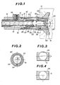
- an operating part 11 of an endoscope contains a relay lens 13 fitted within a tube 12 and arranged to extend towards the rear of an input objective (not shown) at the front end of the inserted part of the endoscope, and a light guide 15 connected to a light source (not shown) via a coupling 14 and a flexible cable (not shown).
- the light guide 15 is fitted on the outer periphery of the tube 12 and it also extends to the front end of the inserted part of the endoscope.
- An outer tube 16' is screwed to the rear of the body 16 of the operating part 11 and sealed by an 0-ring 17.
- An eyepiece frame 19 sealed by an eyepiece window 18 is screwed to the rear end of this outer tube 16'.
- the interior of the endoscope is filled with an inert gas, such as nitrogen, to prevent frosting of the optical system.
- a photographic camera having an objective lens 20 is removably fitted to the eyepiece frame 19 on the body 16 by an adapter 21 set on the camera with respect to the lens 20, so that, for example, an internal organ within the body cavity.in which the inserted part of the endoscope is inserted can be illuminated via the light guide 15, and an image transmitted through the input objective (not illustrated) at the front end of the inserted part of the endoscope and passed by the relay lens 13 to be focused in the position of a vision field mask 22, and thus form a focused image on a film 24 in the case of a photographic camera, the image being fed out via the eyepiece objective 23 and the camera lens 20.
- the relay lens 13 is secured at its rear end by a lens fixing nut 26 screwed to the rear inner periphery of a fixing frame 25 that is soldered on the rear outer periphery of the tube 12. Further, a focusing frame 28 for the eyepiece objective 23 is screwed to this fixing frame 25 and fixed in position by a lock nut 27.
- a fitting frame 29 carries the vision field mask 22 at its front-end and the objective 23 at its rear end, and is fixed to the focusing frame 28 by a clamping screw 30.
- An optical system holding part 31 having a male screw thread on its outer periphery at its front end is screwed onto a female screw thread formed on the inner periphery at the rear of the operating part body 16, this holding part 31 having tapered holding pieces 32 forming tongues extending inwardly and rearwardly.
- the focusing frame 28 is held by the inner periphery of these holding pieces 32, and is fixed with a binder or by solder so that the observing optical system is held securely fixed without applying any undesirable force.
- the fixed position of the observing optical system may be eccentric with respect to the periphery of the eyepiece, but the eccentricity cannot be corrected by the application of a transverse force, as in a soft endoscope using a fibre-optic bundle, and furthermore any alignment errors introduced by the assembly together of the focusing frame 28 fixed by the lock nut 27 of the focusing means, the eyepiece frame 29 and the photographic adapter 21 will be accumulative, so that in some cases the eccentricity x, that is, the deviation between the centre of the eyepiece frame 19 and the axis of the eyepiece lens 23 may reach 1 mm, for example.
- the deviation x will be produced between the optical axis of the observing optical system of the hard endoscope and the optical axis of the camera, and, as shown in Figure 3 if the eccentricity x is produced transverse to the longitudinal axis of a film 24 in a 35mm camera, for example, the centre axis of an image G will be offset and lead to the loss of detail in the marginal zone that is shown shaded.
- a rotatable eccentric centering frame 33 is fitted between the outer tube 16' and the eyepiece frame 19 as shown in Figure 2, so that the centering frame 33 can be rotated to a setting in which the eccentricity x is substantially eliminated, and the image is central, on the longitudinal axis of the film stock, as the endoscope optical system axis is correctly positioned with respect to the centre of the outer peripheral circle of the centering frame 33, and the outer tube 16 1 and centering frame 33 can then be locked by a clamping screw 34.
- This construction thus enables such an eccentricity x to be minimized or eliminated.
- This centering adjustment may be carried out by using an eccentricity controlling jig (not illustrated) having a screen concentric with the outer peripheral circle of the centering frame 33, and having crossed lines marking the centre position of the focusing lens.
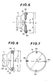
- Figure 5 shows a second embodiment of the invention, in which an eccentric centering ring 35 is fitted on the outer periphery of the eyepiece frame 19, and may be rotated to adjust for correction of any eccentricity x' so that the optical axis coincides with the centre of the eyepiece part, the fitting diameter D and radius A being indicated here to emphasise that the eccentricity x' can usually be completely corrected if a slight eccentricity in a direction normal to the eccentricity x' can be accepted.
- the ring 35 is held by a fixing frame 36 screwed to the eyepiece frame 19 so that the ring 35 can rotate, but not move away from the frame 19.
- the ring 35 is locked in position, when set, by a clamping screw 34.
- the eccentricity x' between the centre of the vision field mask 22, eyepiece 23, and eyepiece frame 19 can be fully corrected by the proper rotational position of the centering ring 35. It may be advantageous to provide a key slot or flat on the adapter 21, to co-operate with a mating portion of the eyepiece frame 19, to identify the x-direction in either of the two embodiments described above.
- Figures 6 and 7 show a third embodiment of the invention, in which a'set of eccentricity controlling screws are disposed around the periphery of the eyepiece frame 19.
- a'set of eccentricity controlling screws are disposed around the periphery of the eyepiece frame 19.
- Figure 6 shows the diamter D and radius l, to emphasise that adjustment may be effected only with respect to one direction, as described with reference to Figure 4. However, it will be apparent from a consideration of Figure 7 that the provision of individual screws enables correction to be completely effective for any direction of deviation.
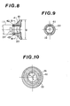
- FIGS 8 to 10 show a fourth embodiment of the invention, in which an eccentric ring 41 similar to the ring 33 or 35 of the first and second embodiments is provided, together with an eccentric eyepiece frame 19. Respective clamping screws 42 and 43 are provided.
- any eccentricity T between the image centre, or centre of the vision field mask 22, and the centre of the operating part body 16 any eccentricity Y between the operating part body 16 and the centering ring 41, and eccentricity Z between the centering ring 41 and the eyepiece frame 19 can be fully eliminated if T + Y ⁇ Z, as it will then be possible to reduce all eccentricity to zero by adjusting the centre of the fitting diameter D of the eyepiece part to which the adapter is fitted and the image centre of the vision field mask 22 by rotating the respective eccentric rings.
- 35 mm. film cameras, 16 mm. cinematic cameras, and television cameras can be used with suitably designed adapters to fit on the eyepiece frame.
Abstract
Description
- This invention relates to endoscopes of the hard type, i.e. having a rigid casing, in which there is mounted an optical system to provide means for inspection or photographic recording of the interior of cavities, for example body cavities in the case of medical use, the endoscope having a relay lens system in the observing optical system, and an eye-piece cap which can be used to locate a photographic or television camera objective.
- Normally, a camera objective is fitted with an adapter to engage and locate upon the eyepiece of an endoscope in order that a body cavity in which the front of the endoscope.is inserted can be photographed for study and diagnosis, for example. However, if the optical axis of the endoscope optical system and the optical axis of the camera objective do not coincide, but are mutually off-set, then there will be some deflection of the image in the camera, which may lead to the loss of information at a marginal zone. Therefore, means may be provided on the camera to correct for any eccentricity of the optical axis of the endoscope. However, if such eccentricity is corrected by means provided on the camera, since it is to be expected that the eccentricity will be different for each individual endoscope, it will be necessary to readjust the eccentricity correction whenever the camera is fitted to the eyepiece of a different endoscope.
- în order to avoid this disadvantage the Japanese utility Model No. 126801/1980 proposes the use of an image guide fixing device for the eyepiece of a soft endoscope, in which the optical system for transmitting images to be observed is formed of a fibre-optic bundle, the above-mentioned eccentricity being forcibly corrected, for example, by a three-point locking screw grip, utilising the flexibility of the fibre bundle. However, in a hard endoscope, in which images are transmitted by a rigid relay lens system, it is impossible to easily adjust the image transmitting optical system by force, as in the above-mentioned device disclosed in Japanese Utility Model No, 126801/1980.
- An adapter device is disclosed in U.S. Patent No. 4,196,990, by which it is possible to correct for the above-mentioned eccentricity by moving a vision field mask in a falsely focusing position. However, if such a vision field mask is moved, in this way, the entire image will be deflected from the optical axis of the endoscope eyepiece, and the resolving power and picture quality will be reduced, which is most undesirable.
- An object of the present invention, is to provide means for a hard endoscope to take photographs with a removable camera fitted to the eyepiece part, and correct for any eccentricity by means which mutually align the optical axis of the observing optical system and the optical axis of the camera, these correcting means being provided in the endoscope eyepiece structure.
- Any eccentricity of the optical axis of the observing optical system of the hard endoscope with respect to the optical axis of the camera can then be easily controlled so as to be minimised or eliminated, without applying any undesirable force to the optical system of the endoscope,and so preventing nonuniformity. That could lead to loss of information in the image, and yet the image position is easy to see, and the target position to be photographed or recorded can be set on the central axis of the camera optical system, where aberrations are small. Furthermore, no centering mechanism is required on the camera and it is not necessary to correct for any eccentricity whenever a camera is fitted to respectively different hard endoscopes, if they are all constructed in accordance with the invention and correcting set up.
- The invention will now be described with reference to the drawings, in which:-
- Figure 1 is a vertical. section showing an eyepiece and associated operating part of one exemplary embodiment of an endoscope according to the present invention;
- Figure 2 is a cross-section on line A-A of Figure 1;
- Figure 3 is a schematic explanatory plan view showing the state of a photographic image in a case where the optical axis of the observing optical system of a hard endoscope and the optical axis of the photographing device side are not mutually aligned;
- Figure 4 is a schematic explanatory plan view showing the state of a photographic image after the eccentricity shown in Figure 3 has been. corrected;
- Figure 5 is a partly sectioned elevation showing part of the eyepiece part of a second exemplary embodiment of the present invention;
- Figure 6 is a partly sectioned elevation showing part of the eyepiece of a third exemplary embodiment of the present invention;
- Figure 7 is an explanatory plan View relating to the embodiment shown in Figure 6;
- Figure 8 is a sectional view of the eyepiece of a fourth exemplary embodiment of the present invention;
- Figure 9 is a cross-section on line B-B of Figure 8; and
- Figure 10 is an explanatory cross-section relating to the embodiment shown in Figure 8.
- The first embodiment of the present invention will now be explained with reference to Figures 1 to 4. In these drawings, an operating part 11 of an endoscope contains a
relay lens 13 fitted within atube 12 and arranged to extend towards the rear of an input objective (not shown) at the front end of the inserted part of the endoscope, and alight guide 15 connected to a light source (not shown) via acoupling 14 and a flexible cable (not shown). Thelight guide 15 is fitted on the outer periphery of thetube 12 and it also extends to the front end of the inserted part of the endoscope. An outer tube 16' is screwed to the rear of thebody 16 of the operating part 11 and sealed by an 0-ring 17. Aneyepiece frame 19 sealed by aneyepiece window 18 is screwed to the rear end of this outer tube 16'. The interior of the endoscope is filled with an inert gas, such as nitrogen, to prevent frosting of the optical system. A photographic camera having anobjective lens 20 is removably fitted to theeyepiece frame 19 on thebody 16 by anadapter 21 set on the camera with respect to thelens 20, so that, for example, an internal organ within the body cavity.in which the inserted part of the endoscope is inserted can be illuminated via thelight guide 15, and an image transmitted through the input objective (not illustrated) at the front end of the inserted part of the endoscope and passed by therelay lens 13 to be focused in the position of avision field mask 22, and thus form a focused image on afilm 24 in the case of a photographic camera, the image being fed out via theeyepiece objective 23 and thecamera lens 20. - The
relay lens 13 is secured at its rear end by alens fixing nut 26 screwed to the rear inner periphery of afixing frame 25 that is soldered on the rear outer periphery of thetube 12. Further, a focusingframe 28 for theeyepiece objective 23 is screwed to thisfixing frame 25 and fixed in position by alock nut 27. Afitting frame 29 carries thevision field mask 22 at its front-end and the objective 23 at its rear end, and is fixed to the focusingframe 28 by aclamping screw 30.. An opticalsystem holding part 31 having a male screw thread on its outer periphery at its front end is screwed onto a female screw thread formed on the inner periphery at the rear of theoperating part body 16, this holdingpart 31 having taperedholding pieces 32 forming tongues extending inwardly and rearwardly. The focusingframe 28 is held by the inner periphery of theseholding pieces 32, and is fixed with a binder or by solder so that the observing optical system is held securely fixed without applying any undesirable force. - In an endoscope having a rigid structure, using hard and inflexible optical elements, the fixed position of the observing optical system may be eccentric with respect to the periphery of the eyepiece, but the eccentricity cannot be corrected by the application of a transverse force, as in a soft endoscope using a fibre-optic bundle, and furthermore any alignment errors introduced by the assembly together of the focusing
frame 28 fixed by thelock nut 27 of the focusing means, theeyepiece frame 29 and thephotographic adapter 21 will be accumulative, so that in some cases the eccentricity x, that is, the deviation between the centre of theeyepiece frame 19 and the axis of theeyepiece lens 23 may reach 1 mm, for example. If a camera is fitted to a hard endoscope having this eccentricity x by means of anadapter 21, the deviation x will be produced between the optical axis of the observing optical system of the hard endoscope and the optical axis of the camera, and, as shown in Figure 3 if the eccentricity x is produced transverse to the longitudinal axis of afilm 24 in a 35mm camera, for example, the centre axis of an image G will be offset and lead to the loss of detail in the marginal zone that is shown shaded. - Therefore, in this embodiment of the invention, a rotatable
eccentric centering frame 33 is fitted between the outer tube 16' and theeyepiece frame 19 as shown in Figure 2, so that thecentering frame 33 can be rotated to a setting in which the eccentricity x is substantially eliminated, and the image is central, on the longitudinal axis of the film stock, as the endoscope optical system axis is correctly positioned with respect to the centre of the outer peripheral circle of thecentering frame 33, and theouter tube 161 and centeringframe 33 can then be locked by aclamping screw 34. This construction thus enables such an eccentricity x to be minimized or eliminated. - This centering adjustment may be carried out by using an eccentricity controlling jig (not illustrated) having a screen concentric with the outer peripheral circle of the centering
frame 33, and having crossed lines marking the centre position of the focusing lens. - After eliminating such an eccentricity or reducing it to a minimum, deviation between the centre of the eyepiece frame .19 and the centre of the
vision field mask 22 andeyepiece 23 is effectively corrected, and if a photographing camera is fitted to theeyepiece frame 19 of the hard endoscope by anadapter 21, the deviation between the optical axis of the observing optical system of the endoscope and the optical axis of the camera will be minimised or eliminated, so that as shown in Figure 4, the axis of thefilm face 24 and the axis of the image G will coincide, or the image centre will lie on the longitudinal axis of the film, which will not lead to any loss of image area, even if the image centre and film centre do not coincide, and any cropping of the upper and lower edges, as drawn, will be the same. - Figure 5 shows a second embodiment of the invention, in which an
eccentric centering ring 35 is fitted on the outer periphery of theeyepiece frame 19, and may be rotated to adjust for correction of any eccentricity x' so that the optical axis coincides with the centre of the eyepiece part, the fitting diameter D and radius A being indicated here to emphasise that the eccentricity x' can usually be completely corrected if a slight eccentricity in a direction normal to the eccentricity x' can be accepted. Thering 35 is held by afixing frame 36 screwed to theeyepiece frame 19 so that thering 35 can rotate, but not move away from theframe 19. Thering 35 is locked in position, when set, by aclamping screw 34. - By this formation, the eccentricity x' between the centre of the
vision field mask 22,eyepiece 23, andeyepiece frame 19 can be fully corrected by the proper rotational position of thecentering ring 35. It may be advantageous to provide a key slot or flat on theadapter 21, to co-operate with a mating portion of theeyepiece frame 19, to identify the x-direction in either of the two embodiments described above. - Figures 6 and 7 show a third embodiment of the invention, in which a'set of eccentricity controlling screws are disposed around the periphery of the
eyepiece frame 19. In the embodiment shown, there are four such screws, 37, 38, 39 and 40, with hemispherical heads, screwed to the outer periphery of theeyepiece frame 19, and individually adjusted to project by respective heights h, h', in such a manner that their heads define a fitting diameter D to absorb the eccentricity x''', and are bonded and fixed after this adjustment. Figure 6 shows the diamter D and radius ℓ, to emphasise that adjustment may be effected only with respect to one direction, as described with reference to Figure 4. However, it will be apparent from a consideration of Figure 7 that the provision of individual screws enables correction to be completely effective for any direction of deviation. - Figures 8 to 10 show a fourth embodiment of the invention, in which an
eccentric ring 41 similar to thering eccentric eyepiece frame 19.Respective clamping screws vision field mask 22, and the centre of theoperating part body 16, any eccentricity Y between theoperating part body 16 and thecentering ring 41, and eccentricity Z between thecentering ring 41 and theeyepiece frame 19 can be fully eliminated if T + Y ≧ Z, as it will then be possible to reduce all eccentricity to zero by adjusting the centre of the fitting diameter D of the eyepiece part to which the adapter is fitted and the image centre of thevision field mask 22 by rotating the respective eccentric rings. As there is only one centering means provided in the first and second embodiments, the eccentricity can be minimised but may not be reduced to zero in any direction of deviation, as has been described with reference to Figure 4, as it will become zero only when T = Y. - It should be emphasised that 35 mm. film cameras, 16 mm. cinematic cameras, and television cameras can be used with suitably designed adapters to fit on the eyepiece frame.
- It will also be apparent that different working modes can be employed, and various structures without departing from the scope of the present invention, as defined in the appended claims.
Claims (5)
Priority Applications (1)
| Application Number | Priority Date | Filing Date | Title |
|---|---|---|---|
| AT82300434T ATE18981T1 (en) | 1981-02-03 | 1982-01-28 | ENDOSCOPES. |
Applications Claiming Priority (2)
| Application Number | Priority Date | Filing Date | Title |
|---|---|---|---|
| JP14545/81 | 1981-02-03 | ||
| JP56014545A JPS57129407A (en) | 1981-02-03 | 1981-02-03 | Hard endoscope |
Publications (2)
| Publication Number | Publication Date |
|---|---|
| EP0058020A1 true EP0058020A1 (en) | 1982-08-18 |
| EP0058020B1 EP0058020B1 (en) | 1986-04-09 |
Family
ID=11864119
Family Applications (1)
| Application Number | Title | Priority Date | Filing Date |
|---|---|---|---|
| EP82300434A Expired EP0058020B1 (en) | 1981-02-03 | 1982-01-28 | Endoscopes |
Country Status (5)
| Country | Link |
|---|---|
| US (1) | US4440157A (en) |
| EP (1) | EP0058020B1 (en) |
| JP (1) | JPS57129407A (en) |
| AT (1) | ATE18981T1 (en) |
| DE (1) | DE3270343D1 (en) |
Cited By (5)
| Publication number | Priority date | Publication date | Assignee | Title |
|---|---|---|---|---|
| EP0501088A1 (en) * | 1991-02-21 | 1992-09-02 | Richard Wolf GmbH | Endoscope with proximal coupled camera |
| DE19927631C1 (en) * | 1999-06-17 | 2000-11-23 | Winter & Ibe Olympus | Endoscope optical system has image viewing device adjusted relative to associated light conductor via adapter between image viewing device and its seating at proximal end of endoscope |
| WO2006130730A3 (en) * | 2005-06-01 | 2007-04-19 | Cannuflow Inc | Protective cap for arthroscopic instruments |
| AT513009A1 (en) * | 2012-06-11 | 2013-12-15 | Swarovski Optik Kg | Lens for an image recorder |
| DE102020205659A1 (en) | 2020-05-05 | 2021-11-11 | Richard Wolf Gmbh | ENDOSCOPE |
Families Citing this family (14)
| Publication number | Priority date | Publication date | Assignee | Title |
|---|---|---|---|---|
| US4651201A (en) * | 1984-06-01 | 1987-03-17 | Arnold Schoolman | Stereoscopic endoscope arrangement |
| US4624243A (en) * | 1985-04-08 | 1986-11-25 | American Hospital Supply Corp. | Endoscope having a reusable eyepiece and a disposable distal section |
| US4905082A (en) * | 1987-05-06 | 1990-02-27 | Olympus Optical Co., Ltd. | Rigid video endoscope having a detachable imaging unit |
| US4854302A (en) * | 1987-11-12 | 1989-08-08 | Welch Allyn, Inc. | Video equipped endoscope with needle probe |
| US4844071A (en) * | 1988-03-31 | 1989-07-04 | Baxter Travenol Laboratories, Inc. | Endoscope coupler device |
| US5205280A (en) * | 1990-12-21 | 1993-04-27 | Mp Video, Inc. | Quick-release endoscopic coupling assembly |
| US5634881A (en) * | 1995-10-20 | 1997-06-03 | United States Surgical Corporation | Laparoscope |
| US5951463A (en) * | 1998-03-18 | 1999-09-14 | Clarus Medical Systems, Inc. | Hand-held endoscopic viewing system |
| JP5242221B2 (en) * | 2008-03-31 | 2013-07-24 | オリンパス株式会社 | Imaging apparatus, electronic endoscope, and assembling method of imaging apparatus |
| JP5563178B1 (en) * | 2012-12-17 | 2014-07-30 | オリンパスメディカルシステムズ株式会社 | Endoscope and endoscope manufacturing method |
| CN103913835B (en) * | 2012-12-29 | 2016-05-25 | 上海澳华光电内窥镜有限公司 | A kind of eyepiece device of adjustable center |
| CN104873164B (en) * | 2014-02-27 | 2017-04-19 | 北京威斯顿亚太光电仪器有限公司 | Separable optical hard-tube lens based on LED illumination |
| DE102016117805A1 (en) | 2016-09-21 | 2018-03-22 | Henke-Sass, Wolf Gmbh | Endoscope and method for centering an eyepiece in a main part of an endoscope |
| DE102018106469A1 (en) * | 2018-03-20 | 2019-09-26 | Olympus Winter & Ibe Gmbh | Method for centering optical elements |
Citations (8)
| Publication number | Priority date | Publication date | Assignee | Title |
|---|---|---|---|---|
| DE2358785A1 (en) * | 1973-11-26 | 1975-06-05 | Licentia Gmbh | Optical adjustable connecting device - aligns optical components on common optical axis and uses hollow cylindrical eccentric guide |
| US3936143A (en) * | 1974-04-15 | 1976-02-03 | Aoi Sansho Kabushiki Kaisha | Optical fibre end connector |
| GB1486681A (en) * | 1975-05-13 | 1977-09-21 | Standard Telephones Cables Ltd | Optical fibre termination |
| US4146300A (en) * | 1976-09-11 | 1979-03-27 | Itt Industries, Inc. | Fiber optic eccentric connector |
| US4181401A (en) * | 1978-03-24 | 1980-01-01 | S. C. Cabling, Inc. | Fiber optic waveguide connector |
| US4196990A (en) * | 1979-02-23 | 1980-04-08 | Polaroid Corporation | Adapter for coupling a photographic camera with a viewing device |
| DE3019502A1 (en) * | 1979-05-25 | 1980-11-27 | Olympus Optical Co | ENDOSCOPE |
| DE2923490A1 (en) * | 1979-06-09 | 1980-12-11 | Standard Elektrik Lorenz Ag | Connecting plug for fibre=optic cable - has end of core adjustable along axis and has socket and centring grub screws around circumference |
Family Cites Families (8)
| Publication number | Priority date | Publication date | Assignee | Title |
|---|---|---|---|---|
| US3638643A (en) * | 1967-10-17 | 1972-02-01 | Hotchkiss Instr Inc | Endoscope for photographic recording |
| US3740449A (en) * | 1971-06-24 | 1973-06-19 | Conn C Ltd | Electric organ with chord playing and rhythm systems |
| JPS5713294B2 (en) * | 1973-03-31 | 1982-03-16 | ||
| US4068932A (en) * | 1975-05-23 | 1978-01-17 | Canon Kabushiki Kaisha | Optical instrument for examining the eye fundus |
| US4102563A (en) * | 1975-12-01 | 1978-07-25 | Canon Kabushiki Kaisha | Eye fundus camera free from undesired reflected and diffused light beams |
| JPS53144193A (en) * | 1977-05-20 | 1978-12-15 | Canon Kk | Ophthalmologic machine having operating distance detector |
| US4264167A (en) * | 1980-02-04 | 1981-04-28 | Polaroid Corporation | Adapter for coupling a camera with a viewing device |
| JPS5782640A (en) * | 1980-11-10 | 1982-05-24 | Matsushita Seiko Co Ltd | Operation controlling device for air-conditioning unit |
-
1981
- 1981-02-03 JP JP56014545A patent/JPS57129407A/en active Pending
-
1982
- 1982-01-28 AT AT82300434T patent/ATE18981T1/en active
- 1982-01-28 EP EP82300434A patent/EP0058020B1/en not_active Expired
- 1982-01-28 DE DE8282300434T patent/DE3270343D1/en not_active Expired
- 1982-02-02 US US06/344,952 patent/US4440157A/en not_active Expired - Lifetime
Patent Citations (8)
| Publication number | Priority date | Publication date | Assignee | Title |
|---|---|---|---|---|
| DE2358785A1 (en) * | 1973-11-26 | 1975-06-05 | Licentia Gmbh | Optical adjustable connecting device - aligns optical components on common optical axis and uses hollow cylindrical eccentric guide |
| US3936143A (en) * | 1974-04-15 | 1976-02-03 | Aoi Sansho Kabushiki Kaisha | Optical fibre end connector |
| GB1486681A (en) * | 1975-05-13 | 1977-09-21 | Standard Telephones Cables Ltd | Optical fibre termination |
| US4146300A (en) * | 1976-09-11 | 1979-03-27 | Itt Industries, Inc. | Fiber optic eccentric connector |
| US4181401A (en) * | 1978-03-24 | 1980-01-01 | S. C. Cabling, Inc. | Fiber optic waveguide connector |
| US4196990A (en) * | 1979-02-23 | 1980-04-08 | Polaroid Corporation | Adapter for coupling a photographic camera with a viewing device |
| DE3019502A1 (en) * | 1979-05-25 | 1980-11-27 | Olympus Optical Co | ENDOSCOPE |
| DE2923490A1 (en) * | 1979-06-09 | 1980-12-11 | Standard Elektrik Lorenz Ag | Connecting plug for fibre=optic cable - has end of core adjustable along axis and has socket and centring grub screws around circumference |
Non-Patent Citations (1)
| Title |
|---|
| Applied Optics, Vol. 16, No. 5, May 1977 New York (US) H. TSUCHIYA et al.: "Double Eccentric Connectors for Optical Fibers" pages 1323-1331 * page 1328, Section IV; figure 12 * * |
Cited By (11)
| Publication number | Priority date | Publication date | Assignee | Title |
|---|---|---|---|---|
| EP0501088A1 (en) * | 1991-02-21 | 1992-09-02 | Richard Wolf GmbH | Endoscope with proximal coupled camera |
| US5307804A (en) * | 1991-02-21 | 1994-05-03 | Richard Wolf Gmbh | Endoscope having a camera coupled thereto |
| DE19927631C1 (en) * | 1999-06-17 | 2000-11-23 | Winter & Ibe Olympus | Endoscope optical system has image viewing device adjusted relative to associated light conductor via adapter between image viewing device and its seating at proximal end of endoscope |
| WO2006130730A3 (en) * | 2005-06-01 | 2007-04-19 | Cannuflow Inc | Protective cap for arthroscopic instruments |
| US7553278B2 (en) | 2005-06-01 | 2009-06-30 | Cannuflow, Inc. | Protective cap for arthroscopic instruments |
| US9167955B2 (en) | 2005-06-01 | 2015-10-27 | Cannuflow, Inc. | Protective cap for arthroscopic instruments |
| AT513009A1 (en) * | 2012-06-11 | 2013-12-15 | Swarovski Optik Kg | Lens for an image recorder |
| US9883087B2 (en) | 2012-06-11 | 2018-01-30 | Swarovski-Optik Kg. | Objective for an image recording device |
| AT513009B1 (en) * | 2012-06-11 | 2021-02-15 | Swarovski Optik Kg | Lens for an image recording device |
| DE102020205659A1 (en) | 2020-05-05 | 2021-11-11 | Richard Wolf Gmbh | ENDOSCOPE |
| DE102020205659B4 (en) | 2020-05-05 | 2023-11-02 | Richard Wolf Gmbh | endoscope |
Also Published As
| Publication number | Publication date |
|---|---|
| US4440157A (en) | 1984-04-03 |
| JPS57129407A (en) | 1982-08-11 |
| ATE18981T1 (en) | 1986-04-15 |
| DE3270343D1 (en) | 1986-05-15 |
| EP0058020B1 (en) | 1986-04-09 |
Similar Documents
| Publication | Publication Date | Title |
|---|---|---|
| EP0058020B1 (en) | Endoscopes | |
| US5051824A (en) | Electronic scope having detachable frame to which solid state imaging device is fastened | |
| US6483535B1 (en) | Wide angle lens system for electronic imagers having long exit pupil distances | |
| US6383131B1 (en) | Stereoscopic endoscope | |
| US5140352A (en) | Ccd camera and method for fundus imaging | |
| JP4716595B2 (en) | Endoscope apparatus and method for assembling endoscope optical adapter | |
| US6338711B1 (en) | Stereoscopic endoscope | |
| JP3220538B2 (en) | Stereoscopic endoscope and stereoscopic endoscope device | |
| WO1992001415A1 (en) | Dental camera system | |
| US4930883A (en) | Photovisual star diagonal | |
| US4580886A (en) | Rotatable snorkel system | |
| US4195922A (en) | Snorkel camera system | |
| US4375913A (en) | Snorkel system | |
| JPS6266220A (en) | Endoscope | |
| US4963906A (en) | Fiber-optically coupled video viewfinder | |
| JP3257641B2 (en) | Stereoscopic endoscope device | |
| US4834516A (en) | Noninverting photo-microscope with variable power lenses | |
| US20040027657A1 (en) | Binoculars | |
| GB2155192A (en) | High speed tv camera | |
| JP3554398B2 (en) | Stereoscopic adapter for endoscope | |
| JP2595747Y2 (en) | Microscope video camera device | |
| JPS63281121A (en) | Optical adaptor device for endoscope | |
| JPH06331903A (en) | Television camera connecting lens barrel | |
| JPS60165614A (en) | Assembling method of hard endoscope | |
| JPS63281115A (en) | Optical connector |
Legal Events
| Date | Code | Title | Description |
|---|---|---|---|
| PUAI | Public reference made under article 153(3) epc to a published international application that has entered the european phase |
Free format text: ORIGINAL CODE: 0009012 |
|
| AK | Designated contracting states |
Designated state(s): AT BE CH DE FR GB IT NL SE |
|
| 17P | Request for examination filed |
Effective date: 19821204 |
|
| GRAA | (expected) grant |
Free format text: ORIGINAL CODE: 0009210 |
|
| AK | Designated contracting states |
Kind code of ref document: B1 Designated state(s): AT BE CH DE FR GB IT LI NL SE |
|
| PG25 | Lapsed in a contracting state [announced via postgrant information from national office to epo] |
Ref country code: NL Effective date: 19860409 Ref country code: LI Effective date: 19860409 Ref country code: IT Free format text: LAPSE BECAUSE OF FAILURE TO SUBMIT A TRANSLATION OF THE DESCRIPTION OR TO PAY THE FEE WITHIN THE PRESCRIBED TIME-LIMIT;WARNING: LAPSES OF ITALIAN PATENTS WITH EFFECTIVE DATE BEFORE 2007 MAY HAVE OCCURRED AT ANY TIME BEFORE 2007. THE CORRECT EFFECTIVE DATE MAY BE DIFFERENT FROM THE ONE RECORDED. Effective date: 19860409 Ref country code: FR Free format text: THE PATENT HAS BEEN ANNULLED BY A DECISION OF A NATIONAL AUTHORITY Effective date: 19860409 Ref country code: CH Effective date: 19860409 Ref country code: BE Effective date: 19860409 Ref country code: AT Effective date: 19860409 |
|
| REF | Corresponds to: |
Ref document number: 18981 Country of ref document: AT Date of ref document: 19860415 Kind code of ref document: T |
|
| PG25 | Lapsed in a contracting state [announced via postgrant information from national office to epo] |
Ref country code: SE Effective date: 19860430 |
|
| REF | Corresponds to: |
Ref document number: 3270343 Country of ref document: DE Date of ref document: 19860515 |
|
| REG | Reference to a national code |
Ref country code: CH Ref legal event code: PL |
|
| EN | Fr: translation not filed | ||
| NLV1 | Nl: lapsed or annulled due to failure to fulfill the requirements of art. 29p and 29m of the patents act | ||
| PLBE | No opposition filed within time limit |
Free format text: ORIGINAL CODE: 0009261 |
|
| STAA | Information on the status of an ep patent application or granted ep patent |
Free format text: STATUS: NO OPPOSITION FILED WITHIN TIME LIMIT |
|
| 26N | No opposition filed | ||
| GBPC | Gb: european patent ceased through non-payment of renewal fee | ||
| PG25 | Lapsed in a contracting state [announced via postgrant information from national office to epo] |
Ref country code: GB Effective date: 19881121 |
|
| PGFP | Annual fee paid to national office [announced via postgrant information from national office to epo] |
Ref country code: DE Payment date: 19960126 Year of fee payment: 15 |
|
| PG25 | Lapsed in a contracting state [announced via postgrant information from national office to epo] |
Ref country code: DE Effective date: 19971001 |