EP0060310A1 - Insert sleeve - Google Patents
Insert sleeve Download PDFInfo
- Publication number
- EP0060310A1 EP0060310A1 EP81101851A EP81101851A EP0060310A1 EP 0060310 A1 EP0060310 A1 EP 0060310A1 EP 81101851 A EP81101851 A EP 81101851A EP 81101851 A EP81101851 A EP 81101851A EP 0060310 A1 EP0060310 A1 EP 0060310A1
- Authority
- EP
- European Patent Office
- Prior art keywords
- sleeve
- ribs
- push
- axially
- elastic
- Prior art date
- Legal status (The legal status is an assumption and is not a legal conclusion. Google has not performed a legal analysis and makes no representation as to the accuracy of the status listed.)
- Granted
Links
Images
Classifications
-
- F—MECHANICAL ENGINEERING; LIGHTING; HEATING; WEAPONS; BLASTING
- F16—ENGINEERING ELEMENTS AND UNITS; GENERAL MEASURES FOR PRODUCING AND MAINTAINING EFFECTIVE FUNCTIONING OF MACHINES OR INSTALLATIONS; THERMAL INSULATION IN GENERAL
- F16L—PIPES; JOINTS OR FITTINGS FOR PIPES; SUPPORTS FOR PIPES, CABLES OR PROTECTIVE TUBING; MEANS FOR THERMAL INSULATION IN GENERAL
- F16L17/00—Joints with packing adapted to sealing by fluid pressure
- F16L17/02—Joints with packing adapted to sealing by fluid pressure with sealing rings arranged between outer surface of pipe and inner surface of sleeve or socket
- F16L17/04—Joints with packing adapted to sealing by fluid pressure with sealing rings arranged between outer surface of pipe and inner surface of sleeve or socket with longitudinally split or divided sleeve
-
- F—MECHANICAL ENGINEERING; LIGHTING; HEATING; WEAPONS; BLASTING
- F16—ENGINEERING ELEMENTS AND UNITS; GENERAL MEASURES FOR PRODUCING AND MAINTAINING EFFECTIVE FUNCTIONING OF MACHINES OR INSTALLATIONS; THERMAL INSULATION IN GENERAL
- F16L—PIPES; JOINTS OR FITTINGS FOR PIPES; SUPPORTS FOR PIPES, CABLES OR PROTECTIVE TUBING; MEANS FOR THERMAL INSULATION IN GENERAL
- F16L37/00—Couplings of the quick-acting type
- F16L37/08—Couplings of the quick-acting type in which the connection between abutting or axially overlapping ends is maintained by locking members
- F16L37/084—Couplings of the quick-acting type in which the connection between abutting or axially overlapping ends is maintained by locking members combined with automatic locking
- F16L37/091—Couplings of the quick-acting type in which the connection between abutting or axially overlapping ends is maintained by locking members combined with automatic locking by means of a ring provided with teeth or fingers
Definitions
- the invention relates to a push-in sleeve mentioned in the preamble of claim 1.
- Such a push-in sleeve is known from EP 2 118 A1.
- Similar push-in sleeves, in which the axially extending ribs are not elastically deformable, are known from the publications DE 26 04 099 A1 and DE 27 56 540 A1.
- the axial ribs arranged in the known push-in sleeves serve to center the tip end inserted into the push-in sleeve and to absorb shear loads.
- Such axial ribs are therefore often referred to briefly as “shear load supports”.
- Shear loads are forces acting transversely to the longitudinal axis of the pipe connector, which act in the sense of a parallel displacement of the axes of the spigot end and the sleeve.
- the shear load supports known from the document DE 27 56 540 A1 and from the document DE 26 04 099 A1 are formed from the rigid sleeve and are not elastically deformable.
- the radially inner guide surfaces of the axial ribs are designed to be conical, whereby a centering effect and an absorption of the shear load are brought about, but no contribution is made to absorb buckling forces which are in the sense of The axes of the tip end and the push-in socket bend.
- the axial ribs according to the document DE 26 04 099 A1 with their radially inner edges are essentially axial, but the inside diameter of the sleeve defined by the inner edges of these ribs must be at least slightly larger than the largest possible within the tolerance range Outside diameter of the tip end to be inserted. This requires a relatively large game, especially with diameters of the tip end in the lower tolerance range, so that the contribution of these axial ribs to the improvement of the shear load resistance is only moderate.
- the radial ribs known from EP 2 118 A1 which serve as shear load supports, are, in contrast to the axial ribs discussed above, elastically deformable, but due to their shape from the dimensionally stable sleeve sleeve, they can only be deformed to a limited extent, namely in a resilient manner.
- Such shear load supports are able to compensate for non-rounding of the tip end and deviations of the outer actual diameter of the tip end from nominal values, but only within a relatively narrow tolerance range.
- the invention has for its object to provide an insertion sleeve of the type mentioned, which is able to reliably and effectively support spiked ends against shear load and buckling forces, the outer diameter of which can vary within a large tolerance range due to the manufacturing process.
- the object on which the invention is based is thus achieved in that the axially extending and elastically deformable ribs in the interior of the push-in sleeve, which serve as a shear load support, consist of a full rubber-elastic material which is different from the shaping material of the sleeve.
- This has the effect that the axial ribs can be strongly and very strongly both elastically deformed and pressed, without thereby jeopardizing the rigidity or the dimensional stability or durability of the sleeve.
- the inside diameter defined by the inner edges of such elastically elastic ribs can be made substantially smaller than the smallest outside diameter of the tip end to be inserted in the tolerance range, without the plug sleeve being deformed or damaged when a tip end is inserted with a diameter which is large within the tolerance range. Rather, pipes with diameters both in the region of the smallest and in the region of the largest diameter which is permissible in the tolerance range are held firmly and securely both against axial pull and, in particular, against the effects of transverse forces. This achieves a substantial stabilization of the pipe plug connection produced with the push-in sleeve of the invention.
- the push-in sleeve of the invention is therefore particularly suitable for the production and use in such push-in sleeves which are cylindrical and sleeve-like and are open on both ends and serve to connect two sleeve-free pipe sections or spigot ends.
- the push-in sleeve of the invention with the elastically deformable inner axially extending ribs is used as shear load supports in connection with a resilient support ring which is arranged axially in front of the annular rubber-elastic sealing elements, i.e. towards the sleeve outlet or sleeve collar.
- the inserted tip end is thereby supported on two ring areas, that is, by the elastically deformable ribs and by the resiliently deformable support ring, the rubber-elastic sealing elements being arranged between these two support rings and being subjected to practically no transverse forces other than the sealing forces.
- a plug-in sleeve designed in this way which is open on both sides, in particular has a surprisingly high transverse rigidity, that is to say a high buckling resistance.
- the rubber-elastic sleeve which serves as the inner lining of the push-in sleeve, preferably has projections and / or recesses which complementarily engage in correspondingly arranged projections or recesses on the inside of the sleeve sleeve, so that a connection secured against axial displacement and radial rotation between the sleeve and the Sleeve is obtained.
- Such securing can alternatively or additionally also be effected by or in connection with the spring-elastic support ring on the sleeve collar.
- the sleeve is preferably made of sheet steel.
- the support ring can be made of spring steel or plastic and can be formed in one piece with the sleeve or can be designed as a separate part which is attached to the sleeve and fastened to it by snapping, sticking, press fitting or welding.
- the push-in sleeve 1 shown in FIG. 1 as an exemplary embodiment of the invention consists of a dimensionally stable sleeve 2 made of corrosion-resistant steel sheet and in this of a rubber-elastic sleeve 3 extending over the entire axial length of the sleeve 2, on which in both collar regions of the push-in sleeve 1 rubber-elastic deformable sealing elements 4 are integrally formed. Seen from the two sleeve collars in the area of the sleeve mirror, i.e. axially centrally in the push-in sleeve 1 shown in FIG.
- axially extending, radially arranged at the same angular distance from one another are elastically deformable ribs 5 formed in one piece from the sleeve 3.
- Both the sleeve 3 and accordingly the ribs 5 consist of a rubber-elastic material, in particular an elastomer with a hardness in the range from 40 to 75 Shore A.
- the axial ribs 5, which serve as a shear load support have a triangular, preferably equilateral, shape in the radial section triangular profile and have on their axially facing the collar collar either either essentially conical shape or are designed with inclined surfaces that form a conical shape overall.
- the end faces of the ribs 5 which are designed in this way and face the collar of the sleeve serve for easier insertion of the tip end onto the radially inner edges 6 of the ribs 5.
- a spring tongue ring 7 made of spring steel is pressed onto the sleeve collar from the outside and has individual bent tongues 8 with which the sleeve 3 is axially fixed in the sleeve 2.
- the axial fixation of the sleeve 3 in the sleeve 2 is further effected by a recess 9 formed in the sleeve 3 and a complementary engagement in this recess 10 which is formed in the sleeve 2.
- the cuff 3 and the sleeve 2 can of course also be formed with a strictly cylindrical outer wall or inner wall and secured in another way, for example by gluing, fixing to the sleeve edge or gluing against relative displacement.
- the spring tongue ring 7 has spring tongues 11 standing radially inward and which serve the additional spring-elastic support of the inserted tip end.
- Such a spigot end inserted into the socket 1 of FIG. 1 is thus supported on two radial surface areas against lateral forces, namely firstly by the elastically deformable ribs 5 and secondly by the resiliently deformable tongues 11 of the resilient spring tongue support ring 7.
- the axial rubber-elastically pressed and deformed ribs 5 alone, but reinforced by the action of the spring-elastic support ring 7 and its spring tongues 11, provide a pipe connector that is largely secured against axial tension. 1 is just held in such a way that it cannot accidentally fall out of the plug connection, even with a vertical detachment, but on the other hand it can also be pulled out of the plug connection again, for example for repair purposes , which then remains usable.
- the spring tongue ring 7 is designed as a separate ring, which is telescopically attached to the collar of the sleeve 2 on this.
- the holding tongues 8 and the spring-elastic supporting spring tongues 11 can of course also be formed in one piece with the sleeve 2.
Abstract
Description
Die Erfindung betrifft eine Steckmuffe der im Oberbegriff des Anspruchs 1 genannten Art.The invention relates to a push-in sleeve mentioned in the preamble of claim 1.
Eine solche Steckmuffe ist aus der Druckschrift EP 2 118 A1 bekannt. Ähnliche Steckmuffen, bei denen die axial verlaufenden Rippen jedoch nicht elastisch verformbar sind, sind aus den Druckschriften DE 26 04 099 A1 und DE 27 56 540 A1 bekannt.Such a push-in sleeve is known from EP 2 118 A1. Similar push-in sleeves, in which the axially extending ribs are not elastically deformable, are known from the publications DE 26 04 099 A1 and DE 27 56 540 A1.
Die in den bekannten Steckmuffen angeordneten axialen Rippen dienen der Zentrierung des in die Steckmuffe eingesteckten Spitzendes sowie dem Auffangen einwirkender Scherlasten. Solche axialen Rippen werden daher häufig kurz als "Scherlaststütze" bezeichnet. "Scherlasten" sind dabei quer zur Längsachse der Rohrsteckverbindung einwirkende Kräfte, die im Sinne einer Parallelversetzung der Achsen des Spitzendes und der Muffe wirken.The axial ribs arranged in the known push-in sleeves serve to center the tip end inserted into the push-in sleeve and to absorb shear loads. Such axial ribs are therefore often referred to briefly as "shear load supports". "Shear loads" are forces acting transversely to the longitudinal axis of the pipe connector, which act in the sense of a parallel displacement of the axes of the spigot end and the sleeve.
Die aus der Druckschrift DE 27 56 540 A1 und aus der Druckschrift DE 26 04 099 A1 bekannten Scherlaststützen sind aus der formsteifen Hülse ausgeformt und sind nicht elastisch verformbar. Bei der aus der Druckschrift DE 27 56 540 A1 bekannten Scherlaststütze sind die radial innenliegenden Führungsflächen der axialen Rippen konisch verlaufend ausgebildet, wodurch zwar ein Zentriereffekt und eine Aufnahme der Scherlast bewirkt wird, aber kein Beitrag zum Auffangen von Knickkräften geleistet wird, die im Sinne einer Durchknickung der Achsen des Spitzendes und der Steckmuffe wirken. Dagegen sind die axialen Rippen gemäß der Druckschrift DE 26 04 099 A1 mit ihren radial innenliegenden Kanten zwar im wesentlichen axial ausgebildet, jedoch muß der durch die Innenkanten dieser Rippen definierte lichte Durchmesser der Muffe zumindest geringfügig größer als der im Toleranzbereich größtmögliche Außendurchmesser des einzusteckenden Spitzendes sein. Dies bedingt ein relativ großes Spiel, insbesondere bei Durchmessern des Spitzendes im unteren Toleranzbereich, so daß der Beitrag dieser axialen Rippen zur Verbesserung der Scherlastfestigkeit nur mäßig ist.The shear load supports known from the document DE 27 56 540 A1 and from the document DE 26 04 099 A1 are formed from the rigid sleeve and are not elastically deformable. In the shear load support known from the document DE 27 56 540 A1, the radially inner guide surfaces of the axial ribs are designed to be conical, whereby a centering effect and an absorption of the shear load are brought about, but no contribution is made to absorb buckling forces which are in the sense of The axes of the tip end and the push-in socket bend. In contrast, the axial ribs according to the document DE 26 04 099 A1 with their radially inner edges are essentially axial, but the inside diameter of the sleeve defined by the inner edges of these ribs must be at least slightly larger than the largest possible within the tolerance range Outside diameter of the tip end to be inserted. This requires a relatively large game, especially with diameters of the tip end in the lower tolerance range, so that the contribution of these axial ribs to the improvement of the shear load resistance is only moderate.
Die aus der Druckschrift EP 2 118 A1 bekannten radialen Rippen, die als Scherlaststützen dienen, sind im Gegensatz zu den vorstehend diskutierten axialen Rippen zwar elastisch verformbar, jedoch durch ihre Ausformung aus der formstabilelastischen Muffenhülse nur in beschränktem Umfang, und zwar federelastisch, verformbar. Solche Querlaststützen vermögen zwar Unrundungen des Spitzendes und Abweichungen des äußeren Istdurchmessers des Spitzendes von Sollwerten aufzufangen, dies jedoch nur innerhalb eines relativ engen Toleranzbereiches. Größere Toleranzbereiche des Außendurchmessers des einzusteckenden Spitzendes können durch diese Scherlaststützen nicht mehr aufgefangen werden, da sonst entweder im Bereich der großen Durchmesser eine zu starke Verformung oder ein Reißen der Hülse der Manschette zu befürchten ist, oder im Bereich kleiner Durchmesser des Spitzendes das Spitzende wie im Fall der aus der Druckschrift DE 26 04 099 A1 bekannten Muffe nicht mehr ausreichend abgestützt ist.The radial ribs known from
Angesichts dieses Standes der Technik liegt der Erfindung die Aufgabe zugrunde, eine Einsteckmuffe der eingangs genannten Art zu schaffen, die auch Spitzenden zuverlässig und wirksam gegen Scherlastkräfte und Knickkräfte abzustützen vermag, deren Außendurchmesser fertigungsbedingt innerhalb eines großen Toleranzbereiches schwanken können.In view of this prior art, the invention has for its object to provide an insertion sleeve of the type mentioned, which is able to reliably and effectively support spiked ends against shear load and buckling forces, the outer diameter of which can vary within a large tolerance range due to the manufacturing process.
Zur Lösung dieser Aufgabe wird eine Steckmuffe der im Oberbegriff des Anspruchs 1 genannten Art geschaffen, die erfindungsgemäß die im kennzeichnenden Teil des Anspruchs 1 genannten Merkmale aufweist.To achieve this object, a push-in sleeve of the type mentioned in the preamble of claim 1 is created, which according to the invention has the features mentioned in the characterizing part of claim 1.
Die der Erfindung zugrunde liegende Aufgabe wird also dadurch gelöst, daß die axial verlaufenden und elastisch verformbaren Rippen im Inneren der Steckmuffe, die als Scherlaststütze dienen, aus einem vollen gummielastischen Werkstoff bestehen, der von dem formgebenden Werkstoff der Hülse verschieden ist. Dadurch wird bewirkt, daß die axialen Rippen stark und sehr stark sowohl gummielastisch verformt als auch verpreßt werden können, ohne daß dadurch die Steifigkeit oder die Formstabilität oder Beständigkeit der Muffe in Frage gestellt werden. Insbesondere kann der durch die Innenkanten solcherart gummielastisch ausgebildeten Rippen definierte lichte Durchmesser wesentlich kleiner als der im Toleranzbereich kleinste Außendurchmesser des einzusteckenden Spitzendes ausgebildet werden, ohne daß die Steckmuffe beim Einstecken eines Spitzendes mit einem im Toleranzbereich großen Durchmesser verformt oder beschädigt wird. Vielmehr werden Rohre mit Durchmessern sowohl im Bereich des kleinsten als auch im Bereich des größten im Toleranzbereich zulässigen Durchmessers fest und sicher sowohl gegen axialen Zug als insbesondere auch gegen Querkrafteinwirkungen gehalten. Dadurch wird eine wesentliche Stabilisierung der mit der Steckmuffe der Erfindung hergestellten Rohrsteckverbindung erreicht. Die Steckmuffe der Erfindung eignet sich daher insbesondere zur Herstellung und zur Verwendung in solchen Steckmuffen, die zylindrisch und hülsenartig ausgebildet und an beiden Stirnseiten offen sind und dem Verbinden zweier muffenloser Rohrabschnitte oder Spitzenden dienen.The object on which the invention is based is thus achieved in that the axially extending and elastically deformable ribs in the interior of the push-in sleeve, which serve as a shear load support, consist of a full rubber-elastic material which is different from the shaping material of the sleeve. This has the effect that the axial ribs can be strongly and very strongly both elastically deformed and pressed, without thereby jeopardizing the rigidity or the dimensional stability or durability of the sleeve. In particular, the inside diameter defined by the inner edges of such elastically elastic ribs can be made substantially smaller than the smallest outside diameter of the tip end to be inserted in the tolerance range, without the plug sleeve being deformed or damaged when a tip end is inserted with a diameter which is large within the tolerance range. Rather, pipes with diameters both in the region of the smallest and in the region of the largest diameter which is permissible in the tolerance range are held firmly and securely both against axial pull and, in particular, against the effects of transverse forces. This achieves a substantial stabilization of the pipe plug connection produced with the push-in sleeve of the invention. The push-in sleeve of the invention is therefore particularly suitable for the production and use in such push-in sleeves which are cylindrical and sleeve-like and are open on both ends and serve to connect two sleeve-free pipe sections or spigot ends.
Vorzugsweise wird die Steckmuffe der Erfindung mit den gummielastisch verformbaren inneren axial verlaufenden Rippen als Scherlaststützen in Verbindung mit einem federelastischen Stützring verwendet, der axial vor den ringförmigen gummielastischen Dichtungselementen, also zum Muffenausgang oder Muffenkragen hin, angeordnet ist. Das eingesteckte Spitzende wird dadurch auf zwei Ringebereichen, also durch die gummielastisch verformbaren Rippen und durch den federelastisch verformbaren Stützring, abgestützt, wobei die gummielastischen Dichtungselemente zwischen diesen beiden Stützringen angeordnet und praktisch keinerlei Querkräften außer den Dichtungskräften ausgesetzt sind. Eine solcherart ausgebildete beidseitig offene Steckmuffe weist insbesondere eine überraschend hohe Quersteifigkeit, also einen hohen Knickwiderstand, auf.Preferably, the push-in sleeve of the invention with the elastically deformable inner axially extending ribs is used as shear load supports in connection with a resilient support ring which is arranged axially in front of the annular rubber-elastic sealing elements, i.e. towards the sleeve outlet or sleeve collar. The inserted tip end is thereby supported on two ring areas, that is, by the elastically deformable ribs and by the resiliently deformable support ring, the rubber-elastic sealing elements being arranged between these two support rings and being subjected to practically no transverse forces other than the sealing forces. A plug-in sleeve designed in this way, which is open on both sides, in particular has a surprisingly high transverse rigidity, that is to say a high buckling resistance.
Die gummielastische, als Innenauskleidung der Steckmuffe dienende Manschette weist vorzugsweise Vorsprünge und/oder Rücksprünge auf, die komplementär in entsprechend auf der Innenseite der Muffenhülse angeordnete Vorsprünge bzw. Rücksprünge eingreifen, so daß eine gegen axiale Verschiebung und radiale Verdrehung gesicherte Verbindung zwischen der Manschette und der Hülse erhalten wird. Eine solche Sicherung kann alternativ oder zusätzlich auch durch oder in Verbindung mit dem federleastischen Stützring am Muffenkragen bewirkt werden.The rubber-elastic sleeve, which serves as the inner lining of the push-in sleeve, preferably has projections and / or recesses which complementarily engage in correspondingly arranged projections or recesses on the inside of the sleeve sleeve, so that a connection secured against axial displacement and radial rotation between the sleeve and the Sleeve is obtained. Such securing can alternatively or additionally also be effected by or in connection with the spring-elastic support ring on the sleeve collar.
Die Hülse besteht vorzugsweise aus Stahlblech. Der Stützring kann aus Federstahl oder Kunststoff bestehen und sowohl einstückig mit der Hülse ausgebildet oder als separates Teil ausgebildet sein, das auf die Hülse aufgesteckt und an dieser durch Einrasten, Festkleben, Preßsitz oder Verschweißen befestigt ist.The sleeve is preferably made of sheet steel. The support ring can be made of spring steel or plastic and can be formed in one piece with the sleeve or can be designed as a separate part which is attached to the sleeve and fastened to it by snapping, sticking, press fitting or welding.
Die Erfindung ist im folgenden an Hand eines Ausführungsbeispiels in Verbindung mit der Zeichnung näher erläutert. Es zeigt die einzige Figur, nämlich die
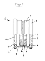
- Fig. 1 teils in Seitensicht, teils im Axialschnitt ein Ausführungsbeispiel der Steckmuffe der Erfindung.
- Fig. 1 partly in side view, partly in axial section an embodiment of the push-in sleeve of the invention.
Die in der Fig. 1 als Ausführungsbeispiel der Erfindung gezeigte Steckmuffe 1 besteht aus einer formstabilen Hülse 2 aus korrosionsbeständigem Stahlblech und in dieser aus einer sich über die gesamte axiale Länge der Hülse 2 erstreckenden gummielastischen Manschette 3, an der in beiden Kragenbereichen der Steckmuffe 1 gummielastisch verformbare Dichtungselemente 4 einstückig angeformt sind. Von den beiden Muffenkragen aus gesehen im Bereich des Muffenspiegels, also axial zentral in der in der Fig. 1 gezeigten Steckmuffe 1, sind axial verlaufende, radial mit gleichem Winkelabstand voneinander angeordnete elastisch verformbare Rippen 5 einstückig aus der Manschette 3 ausgeformt. Sowohl die Manschette 3 als auch dementsprechend die Rippen 5 bestehen aus einem gummielastischen Werkstoff, insbesondere einem Elastomer der Härte im Bereich von 40 bis 75 Shore A. Die axialen Rippen 5, die als Scherlaststütze dienen, weisen im wesentlichen im Radialschnitt ein dreieckiges, vorzugsweise gleichseitig-dreieckiges Profil auf und weisen an ihren axial zum Muffenkragen weisenden Flächen entweder jeweils für sich im wesentlichen Kegelform auf oder sind mit Schrägflächen ausgestaltet, die insgesamt einen konischen Verlauf bilden. Die solcherart ausgebildeten, zum Muffenkragen weisenden Stirnflächen der Rippen 5 dienen der leichteren Einführung des Spitzendes auf die radial innenliegenden Kanten 6 der Rippen 5.The push-in sleeve 1 shown in FIG. 1 as an exemplary embodiment of the invention consists of a dimensionally
Auf die Muffenkragen ist von außen jeweils ein Federzungenring 7 aus Federstahl aufgepreßt, der einzelne umgebogene Zungen 8 aufweist, mit denen die Manschette 3 in der Hülse 2 axial fixiert ist. Die axiale Fixierung der Manschette 3 in der Hülse 2 wird weiterhin durch einen in der Manschette 3 ausgebildeten Rücksprung 9 und einen komplementär in diesen Rücksprung eingreifenden Vorsprung 10 bewirkt, der in der Hülse 2 ausgebildet ist. Die Manschette 3 und die Hülse 2 können selbstverständlich aber auch mit einer streng zylindrischen Außenwand bzw. Innenwand ausgebildet und in anderer Weise, beispielsweise durch Verkleben, Fixieren am Hülsenrand oder Verkleben gegen Relativverschiebungen gegeneinander gesichert sein.A
Der Federzungenring 7 weist nach radial schräg einwärts stehende Federzungen 11 auf, die der zusätzlichen federelastischen Abstützung des eingesteckten Spitzendes dienen. Ein solcherart in die Steckmuffe 1 der Fig. 1 eingestecktes Spitzende ist also auf zwei Radialflächenbereichen gegen Querkräfte abgestützt, nämlich einmal durch die gummielastisch verformbaren Rippen 5 und zum anderen durch die federelastisch verformbaren Zungen 11 des federelastischen Federzungenstützringes 7. Dies führt zu einer hohen Scherlastfestigkeit und Quersteifigkeit der Steckverbindung gegenüber Scherlasten und Knickkräften, ohne daß diese einwirkenden Querkräfte von den Dichtungselementen 4 aufgefangen zu werden brauchen. Außerdem wird durch die axialen gummielastisch verpreßten und verformten Rippen 5 bereits allein, verstärkt aber durch die Wirkung des federelastischen Stützringes 7 und dessen Federzungen 11 eine gegen axialen Zug weitgehend gesicherte Rohrsteckverbindung erhalten. Das in die Steckmuffe der Fig. 1 eingesteckte Spitzende ist dadurch gerade so gehalten, daß es nicht unbeabsichtigt, auch bei senkrechter Aushängung, aus der Steckverbindung herausfallen kann, daß es aber andererseits, beispielsweise zu Reparaturzwecken, durchaus auch wieder aus der Steckverbindung herausgezogen werden kann, die dann weiterverwendbar bleibt.The
Bei dem in der Fig. 1 gezeigten Ausführungsbeispiel ist der Federzungenring 7 als separater Ring ausgebildet, der teleskopartig den Kragen der Hülse 2 übergreifend auf diesem aufgesteckt ist. Alternativ können die Haltezungen 8 und die federelastisch stützenden Federzungen 11 selbstverständlich auch einstückig mit der Hülse 2 ausgebildet sein.In the embodiment shown in FIG. 1, the
Claims (5)
dadurch gekennzeichnet ,
daß die Muffe (1) aus einer formsteifen oder formstabilelastischen Hülse (2) und in dieser einer sich über die gesamte axiale Länge der Hülse erstreckenden gummielastischen Manschette (3) besteht, an der die Dichtungselemente (4) einstückig angeformt sind, und daß die axial verlaufenden Rippen (5) ebenfalls einstückig mit der Manschette (3) ausgebildet sind.1. Push-in sleeve, in particular sleeve-shaped push-in sleeve open on both sides, for producing a pipe plug connection, the sleeve in its collar area carrying at least one annular rubber-elastic sealing element on the inside and radially projecting, axially extending and elastically deformable ribs in the area of the sleeve mirror or axially on the inside behind the sealing element,
characterized ,
that the sleeve (1) consists of a dimensionally stable or dimensionally stable sleeve (2) and in this a rubber-elastic sleeve (3) extending over the entire axial length of the sleeve, on which the sealing elements (4) are integrally formed, and that the axially extending ribs (5) are also integrally formed with the sleeve (3).
dadurch gekennzeichnet,
daß der durch die Innenkanten (6) der Rippen (5) bestimmte lichte Innendurchmesser wesentlich kleiner, vorzugsweise um mindestens 15 % kleiner, als der inner- - halb eines Fertigungstoleranzbereiches kleinste Außendurchmesser des in die Steckmuffe einzusteckenden Spitzendes ist.2. push-in sleeve according to claim 2,
characterized,
that the clear inner diameter determined by the inner edges (6) of the ribs (5) is considerably smaller, preferably at least 15% smaller, than the smallest outer diameter of the spigot end to be inserted into the push-in sleeve within a manufacturing tolerance range.
dadurch gekennzeichnet,
daß die radial innenliegenden Kanten (6) der Rippen (5) zumindest im wesentlichen genau axial verlaufen.3. push-in sleeve according to one of claims 1 or 2,
characterized,
that the radially inner edges (6) of the ribs (5) run at least substantially exactly axially.
dadurch gekennzeichnet,
daß am Muffenkragen axial außen vor den Dichtungselementen (4) ein federelastischer Stützring (7) für das Spitzende angeordnet ist, der die Manschette (3) axial fixiert.4. plug-in sleeve according to one of claims 1 to 3,
characterized,
that on the sleeve collar axially outside in front of the sealing elements (4) a resilient support ring (7) is arranged for the spigot end, which axially fixes the sleeve (3).
dadurch gekennzeichnet ,
daß auf der Außenseite der Manschette (3) vorspringende oder rückspringende Konturen oder Elemente (9) ausgebildet sind, die in komplementäre Elemente (10) oder Konturen eingreifen, die in der Innenwand der Hülse (2) ausgebildet sind.5. push-in sleeve according to one of claims 1 to 4,
characterized ,
that on the outside of the sleeve (3) projecting or recessed contours or elements (9) are formed which engage in complementary elements (10) or contours which are formed in the inner wall of the sleeve (2).
Priority Applications (4)
| Application Number | Priority Date | Filing Date | Title |
|---|---|---|---|
| DE8181101851T DE3171365D1 (en) | 1981-03-12 | 1981-03-12 | Insert sleeve |
| EP81101851A EP0060310B1 (en) | 1981-03-12 | 1981-03-12 | Insert sleeve |
| AT81101851T ATE14341T1 (en) | 1981-03-12 | 1981-03-12 | SOCKET. |
| DE19813122846 DE3122846C2 (en) | 1981-03-12 | 1981-06-09 | sleeve |
Applications Claiming Priority (1)
| Application Number | Priority Date | Filing Date | Title |
|---|---|---|---|
| EP81101851A EP0060310B1 (en) | 1981-03-12 | 1981-03-12 | Insert sleeve |
Publications (2)
| Publication Number | Publication Date |
|---|---|
| EP0060310A1 true EP0060310A1 (en) | 1982-09-22 |
| EP0060310B1 EP0060310B1 (en) | 1985-07-17 |
Family
ID=8187609
Family Applications (1)
| Application Number | Title | Priority Date | Filing Date |
|---|---|---|---|
| EP81101851A Expired EP0060310B1 (en) | 1981-03-12 | 1981-03-12 | Insert sleeve |
Country Status (3)
| Country | Link |
|---|---|
| EP (1) | EP0060310B1 (en) |
| AT (1) | ATE14341T1 (en) |
| DE (1) | DE3171365D1 (en) |
Cited By (5)
| Publication number | Priority date | Publication date | Assignee | Title |
|---|---|---|---|---|
| FR2604507A1 (en) * | 1986-02-18 | 1988-04-01 | Rasmussen Gmbh | INTERLOCKING COUPLING DEVICE FOR CONNECTING THE END OF TWO TUBES |
| US5681062A (en) * | 1995-09-27 | 1997-10-28 | Kunimorikagaku Ltd. | Tubular joint |
| EP1087168A1 (en) * | 1999-09-27 | 2001-03-28 | Legris S.A. | A device for connecting a pipe to a conduit member |
| US6231090B1 (en) * | 1999-03-31 | 2001-05-15 | Kunimorikagaku Co. Ltd. | Tubular joint |
| EP2161486A3 (en) * | 2008-09-08 | 2013-07-31 | Christoph Morach | Pipe sleeve |
Citations (5)
| Publication number | Priority date | Publication date | Assignee | Title |
|---|---|---|---|---|
| US1926197A (en) * | 1932-09-14 | 1933-09-12 | American Hard Rubber Co | Pipe coupling |
| DE1188879B (en) * | 1960-05-18 | 1965-03-11 | Torfit Werke G A Haseke & Co | Socket connection for pipes made of sproedem material |
| BE741333A (en) * | 1969-11-06 | 1970-04-16 | ||
| LU62127A1 (en) * | 1969-12-03 | 1971-05-11 | ||
| US3837683A (en) * | 1973-05-09 | 1974-09-24 | Croix Foundry Ltd Soc | Pipe joint sleeve |
Family Cites Families (3)
| Publication number | Priority date | Publication date | Assignee | Title |
|---|---|---|---|---|
| DE2604099C2 (en) * | 1976-02-03 | 1984-04-26 | Schneider Gmbh & Co, 5020 Frechen | Support ring for a slip-on seal for sleeveless pipes |
| AT347191B (en) * | 1976-12-24 | 1978-12-11 | Eternit Werke Hatschek L | PIPE COUPLING |
| US4126339A (en) * | 1977-11-21 | 1978-11-21 | W. S. Dickey Clay Mfg. Co. | Plain end pipe fitting |
-
1981
- 1981-03-12 AT AT81101851T patent/ATE14341T1/en not_active IP Right Cessation
- 1981-03-12 DE DE8181101851T patent/DE3171365D1/en not_active Expired
- 1981-03-12 EP EP81101851A patent/EP0060310B1/en not_active Expired
Patent Citations (7)
| Publication number | Priority date | Publication date | Assignee | Title |
|---|---|---|---|---|
| US1926197A (en) * | 1932-09-14 | 1933-09-12 | American Hard Rubber Co | Pipe coupling |
| DE1188879B (en) * | 1960-05-18 | 1965-03-11 | Torfit Werke G A Haseke & Co | Socket connection for pipes made of sproedem material |
| BE741333A (en) * | 1969-11-06 | 1970-04-16 | ||
| LU62127A1 (en) * | 1969-12-03 | 1971-05-11 | ||
| DE2059311A1 (en) * | 1969-12-03 | 1971-06-09 | Int D Applic De Procedes Ind S | Connection for coupling pipes |
| US3837683A (en) * | 1973-05-09 | 1974-09-24 | Croix Foundry Ltd Soc | Pipe joint sleeve |
| DE2346344A1 (en) * | 1973-05-09 | 1974-11-21 | Anthes Imperial Ltd | DEVICE FOR SEALING TWO PIPES |
Cited By (7)
| Publication number | Priority date | Publication date | Assignee | Title |
|---|---|---|---|---|
| FR2604507A1 (en) * | 1986-02-18 | 1988-04-01 | Rasmussen Gmbh | INTERLOCKING COUPLING DEVICE FOR CONNECTING THE END OF TWO TUBES |
| US5681062A (en) * | 1995-09-27 | 1997-10-28 | Kunimorikagaku Ltd. | Tubular joint |
| US6231090B1 (en) * | 1999-03-31 | 2001-05-15 | Kunimorikagaku Co. Ltd. | Tubular joint |
| EP1087168A1 (en) * | 1999-09-27 | 2001-03-28 | Legris S.A. | A device for connecting a pipe to a conduit member |
| AU745944B2 (en) * | 1999-09-27 | 2002-04-11 | Legris S.A. | A device for connecting a pipe end to a member |
| US6517124B1 (en) | 1999-09-27 | 2003-02-11 | Legris S.A. | Device for connecting a pipe end to a member |
| EP2161486A3 (en) * | 2008-09-08 | 2013-07-31 | Christoph Morach | Pipe sleeve |
Also Published As
| Publication number | Publication date |
|---|---|
| DE3171365D1 (en) | 1985-08-22 |
| EP0060310B1 (en) | 1985-07-17 |
| ATE14341T1 (en) | 1985-08-15 |
Similar Documents
| Publication | Publication Date | Title |
|---|---|---|
| EP0913534B1 (en) | Manhole for fluid conduits and manhole section therefor | |
| EP0638754B1 (en) | Socket joint with means for locking against axial forces | |
| DE3815167C1 (en) | ||
| EP0612947B1 (en) | Socket joint with means for locking against axial forces | |
| EP0743479B1 (en) | Arrangement for connecting a metal pipe to a receiving sleeve | |
| DE2304676A1 (en) | WORKPIECE, IN PARTICULAR SEALING ELEMENT, MADE OF ELASTIC MATERIAL WITH ELASTIC REINFORCEMENT | |
| DE3336855A1 (en) | SHEAR-PROOF CONNECTOR FOR PIPES, IN PARTICULAR SLEEVE PIPES | |
| EP0159385A1 (en) | Sealing ring, sleeve with a sealing ring and its use | |
| DE3710853A1 (en) | Plug-in connection for a pipe or the like in a receiving part | |
| DE3532545A1 (en) | ELASTIC PIPE CONNECTION, IN PARTICULAR FLEXIBLE PIPE COUPLING | |
| EP0060310B1 (en) | Insert sleeve | |
| DE19723594C2 (en) | Pipe connector | |
| EP2193303A1 (en) | Press fitting for a pipe, in particular plastic pipe or plastic and metal composite pipe | |
| WO1982003440A1 (en) | Sealed coupling of plastic material pipes resisting to thrust forces | |
| DE3338899C2 (en) | Sealing ring | |
| EP1384923B1 (en) | Sealing ring for sealing a length compensation of a universal joint shaft | |
| DE4310795C1 (en) | Plug-in type union between pipes | |
| DE19717185C2 (en) | Pipe connection for short pipes | |
| DE8107112U1 (en) | CONNECTOR | |
| EP0985867A1 (en) | Plastics corrugated tube and the combination of this tube with a sleeve | |
| AT379446B (en) | CONNECTOR | |
| EP0060309B1 (en) | Insert sleeve | |
| DE4315958C2 (en) | Pipe connection between two concentrically overlapping pipe elements | |
| DE19537479C2 (en) | Slotted sleeve | |
| DE3122846C2 (en) | sleeve |
Legal Events
| Date | Code | Title | Description |
|---|---|---|---|
| PUAI | Public reference made under article 153(3) epc to a published international application that has entered the european phase |
Free format text: ORIGINAL CODE: 0009012 |
|
| AK | Designated contracting states |
Designated state(s): AT BE CH DE FR GB IT NL SE |
|
| 17P | Request for examination filed |
Effective date: 19830322 |
|
| GRAA | (expected) grant |
Free format text: ORIGINAL CODE: 0009210 |
|
| AK | Designated contracting states |
Designated state(s): AT BE CH DE FR GB IT LI NL SE |
|
| PG25 | Lapsed in a contracting state [announced via postgrant information from national office to epo] |
Ref country code: NL Effective date: 19850717 Ref country code: IT Free format text: LAPSE BECAUSE OF FAILURE TO SUBMIT A TRANSLATION OF THE DESCRIPTION OR TO PAY THE FEE WITHIN THE PRESCRIBED TIME-LIMIT;WARNING: LAPSES OF ITALIAN PATENTS WITH EFFECTIVE DATE BEFORE 2007 MAY HAVE OCCURRED AT ANY TIME BEFORE 2007. THE CORRECT EFFECTIVE DATE MAY BE DIFFERENT FROM THE ONE RECORDED. Effective date: 19850717 Ref country code: FR Free format text: THE PATENT HAS BEEN ANNULLED BY A DECISION OF A NATIONAL AUTHORITY Effective date: 19850717 Ref country code: BE Effective date: 19850717 |
|
| REF | Corresponds to: |
Ref document number: 14341 Country of ref document: AT Date of ref document: 19850815 Kind code of ref document: T |
|
| PG25 | Lapsed in a contracting state [announced via postgrant information from national office to epo] |
Ref country code: SE Effective date: 19850730 |
|
| REF | Corresponds to: |
Ref document number: 3171365 Country of ref document: DE Date of ref document: 19850822 |
|
| NLV1 | Nl: lapsed or annulled due to failure to fulfill the requirements of art. 29p and 29m of the patents act | ||
| PG25 | Lapsed in a contracting state [announced via postgrant information from national office to epo] |
Ref country code: AT Effective date: 19860312 |
|
| EN | Fr: translation not filed | ||
| PG25 | Lapsed in a contracting state [announced via postgrant information from national office to epo] |
Ref country code: LI Effective date: 19860331 Ref country code: CH Effective date: 19860331 |
|
| PLBE | No opposition filed within time limit |
Free format text: ORIGINAL CODE: 0009261 |
|
| STAA | Information on the status of an ep patent application or granted ep patent |
Free format text: STATUS: NO OPPOSITION FILED WITHIN TIME LIMIT |
|
| 26N | No opposition filed | ||
| GBPC | Gb: european patent ceased through non-payment of renewal fee | ||
| REG | Reference to a national code |
Ref country code: CH Ref legal event code: PL |
|
| PG25 | Lapsed in a contracting state [announced via postgrant information from national office to epo] |
Ref country code: GB Effective date: 19881121 |
|
| PGFP | Annual fee paid to national office [announced via postgrant information from national office to epo] |
Ref country code: DE Payment date: 19920601 Year of fee payment: 12 |
|
| PG25 | Lapsed in a contracting state [announced via postgrant information from national office to epo] |
Ref country code: DE Effective date: 19931201 |