EP0060470A1 - Method and apparatus for non-destructive inspection of tyres - Google Patents
Method and apparatus for non-destructive inspection of tyres Download PDFInfo
- Publication number
- EP0060470A1 EP0060470A1 EP19820101768 EP82101768A EP0060470A1 EP 0060470 A1 EP0060470 A1 EP 0060470A1 EP 19820101768 EP19820101768 EP 19820101768 EP 82101768 A EP82101768 A EP 82101768A EP 0060470 A1 EP0060470 A1 EP 0060470A1
- Authority
- EP
- European Patent Office
- Prior art keywords
- tire
- transmitter
- rings
- mounting
- receiver
- Prior art date
- Legal status (The legal status is an assumption and is not a legal conclusion. Google has not performed a legal analysis and makes no representation as to the accuracy of the status listed.)
- Granted
Links
Images


Classifications
-
- G—PHYSICS
- G01—MEASURING; TESTING
- G01N—INVESTIGATING OR ANALYSING MATERIALS BY DETERMINING THEIR CHEMICAL OR PHYSICAL PROPERTIES
- G01N29/00—Investigating or analysing materials by the use of ultrasonic, sonic or infrasonic waves; Visualisation of the interior of objects by transmitting ultrasonic or sonic waves through the object
- G01N29/44—Processing the detected response signal, e.g. electronic circuits specially adapted therefor
- G01N29/449—Statistical methods not provided for in G01N29/4409, e.g. averaging, smoothing and interpolation
-
- G—PHYSICS
- G01—MEASURING; TESTING
- G01M—TESTING STATIC OR DYNAMIC BALANCE OF MACHINES OR STRUCTURES; TESTING OF STRUCTURES OR APPARATUS, NOT OTHERWISE PROVIDED FOR
- G01M17/00—Testing of vehicles
- G01M17/007—Wheeled or endless-tracked vehicles
- G01M17/02—Tyres
- G01M17/025—Tyres using infrasonic, sonic or ultrasonic vibrations
-
- G—PHYSICS
- G01—MEASURING; TESTING
- G01N—INVESTIGATING OR ANALYSING MATERIALS BY DETERMINING THEIR CHEMICAL OR PHYSICAL PROPERTIES
- G01N29/00—Investigating or analysing materials by the use of ultrasonic, sonic or infrasonic waves; Visualisation of the interior of objects by transmitting ultrasonic or sonic waves through the object
- G01N29/22—Details, e.g. general constructional or apparatus details
- G01N29/26—Arrangements for orientation or scanning by relative movement of the head and the sensor
- G01N29/27—Arrangements for orientation or scanning by relative movement of the head and the sensor by moving the material relative to a stationary sensor
-
- G—PHYSICS
- G01—MEASURING; TESTING
- G01N—INVESTIGATING OR ANALYSING MATERIALS BY DETERMINING THEIR CHEMICAL OR PHYSICAL PROPERTIES
- G01N29/00—Investigating or analysing materials by the use of ultrasonic, sonic or infrasonic waves; Visualisation of the interior of objects by transmitting ultrasonic or sonic waves through the object
- G01N29/34—Generating the ultrasonic, sonic or infrasonic waves, e.g. electronic circuits specially adapted therefor
- G01N29/341—Generating the ultrasonic, sonic or infrasonic waves, e.g. electronic circuits specially adapted therefor with time characteristics
- G01N29/343—Generating the ultrasonic, sonic or infrasonic waves, e.g. electronic circuits specially adapted therefor with time characteristics pulse waves, e.g. particular sequence of pulses, bursts
Definitions
- This invention is generally directed to methods and apparatus for non-destructive inspection of rubber tires. Such inspection techniques may also be combined with conventional tire buffing operations in accordance with this invention.
- Prior tire chucking mechanisms in general have included axially movable tire mounting rims for quickly mounting and inflating a test tire.
- Prior NDI machines have located an ultrasonic transmitter inside a rotatable inflated, tire, albeit such have been only fixed or manually adjustable mounting arrangements.
- Other NDI machines have included articulated transmitter mounting arrangement in conjunction with a spread-open non-inflated test tire.
- an inflated tire in the preferred embodiment has been discovered to assist in maintaining a true running tire surface and thus avoids signal variations that might otherwise be caused by wobbling or other relative axial motions of the tire walls during rotating.
- the inflated tire is also useful in helping to at least partially stress the tire walls, as they will be stressed during normal use, and to open up leakage passageways through the tire walls so that they may be detected by ultrasonic detection of air passing therethrough. Approximately only five psi is needed to maintain a stable inflated tire structure. However, it has been discovered that improved signal transmission and overall performance occurs if the tire is inflated within the range of approximately 15-18 psi.
- the outer treadwall of the tire under inspection first be buffed to present a uniform surface th,is minimizing spurious defect indications that might otherwise be caused by tread patterns and/or by uneven wear spots or patterns in the outer treadwall surface of the tire.
- the tire buffing apparatus and method may be advantageously employed in combination with the ultrasonic non-destructive testing method and apparatus to present a unified, convenient and efficient overall operation. Since such a buffing operation is necessarily involved in tire retreading operations anyway, this combination is particularly attractive where the tire carcasses are being inspected in preparation for retreading.
- the preferred exemplary embodiment of this invention includes special mechanical features for automatically moving the acoustic transducers into and out of operative position with respect to the inflated tire walls.
- the acoustic transmitters are retracted inwardly both radially and axially with respect to at least one tire mounting ring or flange so as both to facilitate the tire mounting and demounting operations and to protect the acoustic transmitters from possible physical damage.
- these acoustic transmitters are moved radially outwardly inside the inflated tire into an operative position with respect to the inside tire walls.
- the array of acoustic receivers is moved radially inwardly towards the outer inflated tire walls to a desired operative position.
- the relative axial movement of the acoustic transmitters with respect to a tire mounting flange or ring is achieved by spring loading the tire ring so that it axially moves away from the acoustic transmitters thereby uncovering them during the tire mounting operation and thus providing proper clearance for subsequent radially outward movement into the inflated tire carcass.
- spring loading also helps in properly seating the tire rims with the mounting flanges or rings during mounting and inflation operations.
- FIGS. 1 and 2 two perspective views of the presently preferred exemplary combined tire buffer and NDI machine are shown. As will be apparent, the NDI features of the machine may be provided, if desired, without including the tire buffing capability.
- the major mechanical components of the machine are mounted to an open frame 100 having a fixed spindle 102 and an axially movable spindle 104 opposingly aligned along horizontal axis 106.
- Conventional circular tire mounting rings or flanges 108 and 110 are attached to the outer rotatable ends of spindles 102 and 104 for mounting an inflated tire 112, therebetween.
- a conventional pneumatically operated tire lift mechanism 114 is conveniently provided so as to assist the human operator in lifting and swinging a tire into and out of place between rings 108 and 110 during tire mounting and demounting operations.
- Ring 108 is driven by a two horsepower d.c. motor 116 through reducing gears 118.
- a tire surface speed of approximately 600 feet per minute is preferred for buffing operations while a much lower speed of approximately 40 feet per minute is preferred for NDI operations.
- Spindle 104, and hence ring 110 is axially extended and retracted by pneumatic cylinder 120.
- ring 110 is retracted by cylinder 120 so as to permit the tire ll2 to be lifted into place on ring 108 by lift 114. Thereafter, ring 110 is extended against the corresponding rim of tire l12 and the tire is inflated to a desired set point pressure by compressed air passed through the center of spindle 102.
- a conventional rotating tire buffing rasp 200 is mounted on a vertical pedestal 202 situated on the backside of the machine as seen in FIG. 2.
- the rasp 200 is controlled via a conventional panel 204 to move laterally along a desired buffing path 206 and horizontaolly towards and away from the tire by conventional control mechanisms including a "joy stick" used to control lead screws and associated drive motors and the like.
- the buffer rasp 200 is rotated by a separate motor mounted on /pedestal 202.
- the buffer mechanism, per se, is of a conventional type as marketed by Bandag, Inc., e.g. Buffer Model No. 23A.
- the receivers 210 preferably include a conically shaped collimator and/or focusing tube to help limit the field of view for each individual transducer to a relatively small and unique area across the tire wall.
- the receivers 210 may be conveniently potted either individually or in groups in a polyurethane foam or the like to help mechanically fix the receivers in their respective desired positions, to help protect the receivers and to help isolate the receivers from spurious ambient acoustic signals.
- the array of receivers 210 is radially adjusted into operative position by an air cylinder 212 having a coupled hydraulic control cylinder so as to define a radially extended operative position for the receivers 210.
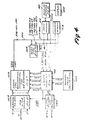
- FIG. 3 A block diagram of the combined tire buffer/NDI machine and its associated electrical and pneumatic circuits is shown in FIG. 3.
- the electrical motor and pneumatic cylinder controls 300 are of entirely conventional design and thus not shown in detail. Operator inputs depicted at the left of FIG. 3 are made directly or indirectly by the opeator via conventional electrical switches, relays, air valves and/or liquid control valves.
- a tire is placed on lift 114 and raised into position between the rings 108 and 110.
- a predetermined index position on the tire is aligned with a physical index position on flange 108.
- the chucking apparatus is engaged by causing flange 110 to move into the tire 112 so as to pinch the tire beads together in preparation for tire inflation.
- the tire is then inflated to a desired set point pressure.
- the flange 108 is spring loaded such that during chuck engagement and tire inflation, it is caused to move axially outwardly agains the spring-loading (e.g by approximately 2 inches).
- An interlock switch activated by air pressure and/or by the physical movement of flange 108 may be used to prevent any premature extension of the transmitter before it is uncovered from its protected position.
- the buffing rasp drive motors are conventionally activated and controlled (e.g. with a "joy stick" and conventional push button controls) to buff the tire tread surface as desired.
- a "joy stick” and conventional push button controls e.g. with a "joy stick" and conventional push button controls.
- Such buffing is believed to avoid possible spurious indications of defects caused by normal tread patterns and/or by uneven wear about the tire surface.
- an ultrasonic transmitter located inside the inflated tire ll2 is extended into operative position and the array of receivers 210 is lowered into operative position by respectively associated pneumatic cylinders.
- the same 2-horsepower d.c. motor which drives the tire at approximately 600 surface feet per minute during buffing operations may be reduced in speed by conventional electrical circuits so as to drive the tire at approximately 40 surface feet per minute during the NDI mode.
- the operator may activate the scan request input switch to the ultrasonic NDI circuits 302.
- the walls of tire 112 will be ultrasonically inspected during one or more complete tire revolutions to produce a display 304 which can be humanly interpreted directly or indirectly to reveal the condition of the tire (e.g. satisfactory for further buffing and retreading, doubtful or unsatisfactory). If questionable condition is indicated, the tire may be discarded or may be additionally buffed and retested.
- the ultrasonic NDI circuits 302 are shown in greater detail at FIG. 4.
- the outputs from the 16 ultrasonic receivers 210 are amplified and multiplexed onto eight signal processing channels A-H by circuits 402.
- Each signal processing channel then provides AGC amplification, rectification, integration and analog-to-digital conversion with the signal processing circuitry 404.
- the resulting digitized outputs are presented to a conventional eight bit data bus 406 which is interconnected to a conventional micro-computer CPU (e.g. an 8080 type of eight bit computer) 408.
- a conventional micro-computer CPU e.g. an 8080 type of eight bit computer
- the CPU 408 is also connected via a conventional address bus 410 and data bus 406 to a dlta memory 412, to a programmable read-only memory (PROM) 414 and to a system interface circuit 416.
- a display interface 418 is directly connected to the data memory banks 412 to provide a CRT type of oscilloscope display.
- the system interface 416 provides the necessary gating and other control signals to the signal processing circuitry 404 and also provides HIGH CHAN multiplexing signals to the preamplifier circuits 402 as well as to the transmitter drivers and multiplexing circuitry 422 used to drive plural ultrasonic transmitters.
- the operation of the entire system is synchronized to the rotational movements of tire 112 through a rotary pulse generator 424 directly driven with the tire (e.g. geared to the reducer gears).
- the rotary pulse generator 424 provides 1,024 pulses per revolution at terminal RPGX and 1 pulse per revolution at terminals RPGY.
- Ultrasonic acoustic transmitting crystals 500 and 502 are disposed inside inflated tire 112, which is chucked between rings 108 and 110, rotatably secured to spindles 102 and 104, respectively.
- the electrical leads feeding transmitters 500 and 502 are fed out through the fixed spindle 102 to the transmitter activation circuits.
- Inflation air is likewise fed in through the center of spindle 102 as are pneumatic lines and/or other control connections for extending and retracting the transmitters.
- the exemplary ultrasonic transmitters 500 and 502 have a radiation field which substantially illuminates a sector of approximately 90°. Hence, they are mounted at 90° with respect to one another on block 504 which may, for example, be formed from polyvinyl chloride plastic materials. It has been found that acceptable operation will not result if the transmitters are too close to the inside tire surfaces or too far away from the surfaces. In the preferred exemplary embodiment, transmitting crystals 500 and 502 are approximately two inches from the inner tire wall surfaces although this optimum distance of separation may be varied by a ,considerable amount (e.g. plus or minus approximately one inch).
- the arrayed receiving transducers 210 are located about an arc generally corresponding to the outside shape of the tire wall. Here again, it has been found that acceptable operation does not result if the receivers are too close or too far away from the outer tire walls. Preferably, the receivers are no closer than approximately 1 inch to the outer tire surface but are preferably within 5.5 to 8.5 inches of the opposingly situated transmitting crystal.
- the receiving transducers 210 preferably each employ a conically shaped collimator and/or focusing tube. These tubes are preferably machined from polyvinyl chloride plastic material and also help to match the impedance of the actual transducer crystal surface to the surrounding ambient air acoustic impedance.
- a moderately high ultrasonic frequency is employed so as to help avoid interference from spurious ambient acoustic signals and to obtain increased resolution by using shorter wavelength acoustic signals while at the same time avoiding ultra-high frequency acoustic signals and the problems associated therewith.
- Frequencies above 40 kHz are desirable with 75 kHz being chosen as the presently preferred optimum frequency.
- the transmitting crystals 500 and 502 are directed at 90° with respect to one another from the face of a PVC mounting block 1500.
- the block 1500 is, in turn, attached to a retractable rod 1502 connected to the piston of a pneumatic cylinder 1504.
- the pneumatic cylinder 1504 has retracted the transmitting crystals 500 and 502 into a protected area defined by an ai alar plate 1506 attached to the tire mounting ring or flange 108.
- the tire mounting ring 108 is rotatably secured to the fixed spindle 102 through ball- bearing assemblies 1508 and 1510. This rotatable connection is maintained airtight by rotating seal assembly 1512.
- the center of the spindle 102 is hollow so as to permit passage of pneumatic control line 1514 and of the transmitter electrical leads therethrough.
- the rotating ring 108 and its connected assembly is spring-loaded via spring 1517 to its axially extended position as shown in FIG. 5.
- the ring 108 may be moved axially to the position shown in dotted lines against'the spring force.
- such motion begins to occur when the ring 108 has approximately 1500 lbs. of lateral force applied thereto.
- the sliding joint which permits such motion is also maintained air tight by "0" ring 1516.
- no more than approximately two inches of axial movement are permitted before the spring force is sufficient to resist further movement even when the tire is inflated to approximately 15-18 psi.
Abstract
Description
- This invention is generally directed to methods and apparatus for non-destructive inspection of rubber tires. Such inspection techniques may also be combined with conventional tire buffing operations in accordance with this invention.
- The invention here claimed is directed to certain mechanical features of the preferred embodiment.
- There has long been an urgent need for cost effective, efficient, non-destructive inspection (NDI) of rubber tire casings. There are obvious safety benefits to be had by such techniques if they can be efficiently and rapidly practiced. There are also potential economic benefits. For example, during tire retreading operations, a defective tire carcass can be discarded before wasting further expenditures of time and money if it can be accurately, efficiently and quickly detected.
- In fact, the need for improved NDI methods and apparatus relating to the testing of tire casings is so great that the U.S. Army Materials and Mechanics Research Center has sponsored special symposia devoted entirely to this subject in 1973, 1974, 1976 and 1978. The proceedings of the first three of these symposia have now been published and are available from the National Technical Information Service. They each include a complete chapter on ultrasonic tire testing as well is other chapters devoted to different tire testing procedures (e.g. holographic, infrared and X-ray). There are also many prior art patents relating generally to the use of ultrasonic waves to non- destructively test pneumatic tire casings. For example:

- There are also several prior art patents relating to mechanical structures for chucking or otherwise physically handling pneumatic tire casings during various types of non-destructive testing or manufacturing processes. For example:

- Although a wide variety of non-destructive ultrasonic tests have been performed on tires in the past as shown by these prior art patents, they have each suffered serious deficiencies and have failed to achieve widespread acceptance in commercial practice.
- Prior tire chucking mechanisms in general have included axially movable tire mounting rims for quickly mounting and inflating a test tire. Prior NDI machines have located an ultrasonic transmitter inside a rotatable inflated, tire, albeit such have been only fixed or manually adjustable mounting arrangements. Other NDI machines have included articulated transmitter mounting arrangement in conjunction with a spread-open non-inflated test tire. However, there has not yet been a commercially viable mechanism arrangement for quickly positioning ultrasonic transducers about an inflated test tire wall while at the same time facilitating quick tire mounting/de-mounting procedures and also protecting the transducers from physical harm.
- It has been discovered that these earlier attempts at ultrasonic non-destructive inspection of tire casings can be considerably improved and made more commercially vaiable.
- The use of an inflated tire in the preferred embodiment has been discovered to assist in maintaining a true running tire surface and thus avoids signal variations that might otherwise be caused by wobbling or other relative axial motions of the tire walls during rotating. The inflated tire is also useful in helping to at least partially stress the tire walls, as they will be stressed during normal use, and to open up leakage passageways through the tire walls so that they may be detected by ultrasonic detection of air passing therethrough. Approximately only five psi is needed to maintain a stable inflated tire structure. However, it has been discovered that improved signal transmission and overall performance occurs if the tire is inflated within the range of approximately 15-18 psi.
- Although it may not be required, it is preferred that the outer treadwall of the tire under inspection first be buffed to present a uniform surface th,is minimizing spurious defect indications that might otherwise be caused by tread patterns and/or by uneven wear spots or patterns in the outer treadwall surface of the tire. In this connection, the tire buffing apparatus and method may be advantageously employed in combination with the ultrasonic non-destructive testing method and apparatus to present a unified, convenient and efficient overall operation. Since such a buffing operation is necessarily involved in tire retreading operations anyway, this combination is particularly attractive where the tire carcasses are being inspected in preparation for retreading.
- The preferred exemplary embodiment of this invention includes special mechanical features for automatically moving the acoustic transducers into and out of operative position with respect to the inflated tire walls. During tire mounting and demounting operations, the acoustic transmitters are retracted inwardly both radially and axially with respect to at least one tire mounting ring or flange so as both to facilitate the tire mounting and demounting operations and to protect the acoustic transmitters from possible physical damage. During or after tire inflation, these acoustic transmitters are moved radially outwardly inside the inflated tire into an operative position with respect to the inside tire walls. At the same time, the array of acoustic receivers is moved radially inwardly towards the outer inflated tire walls to a desired operative position.
- In the preferred exemplary embodiment, the relative axial movement of the acoustic transmitters with respect to a tire mounting flange or ring is achieved by spring loading the tire ring so that it axially moves away from the acoustic transmitters thereby uncovering them during the tire mounting operation and thus providing proper clearance for subsequent radially outward movement into the inflated tire carcass. Such spring loading also helps in properly seating the tire rims with the mounting flanges or rings during mounting and inflation operations.
- These and other objects and advantages of this invention will be better appreciated by reading the following detailed description of the presently preferred exemplary embodiment in conjnction with the accompanying drawings, of which:
- FIGS. 1 and 2 are perspective views of a combined NDI/buffer machine constructed in accordance with this invention;
- FIG. 3 is a block diagram of the invention shown in FIGS. 1 and 2;
- FIG. 4 is a block diagram of the ultrasonic NDI circuits which may be used in the NDI/buffer machine of FIGS. 1-3 or in a machine having only NDI capabilities; and
- FIG. 5 is a detailed cut-away cross-sectional view of the fixed spindle and transmitter mounting arrangement used in the embodiment of FIGS. 1 and 2.
- Referring to FIGS. 1 and 2, two perspective views of the presently preferred exemplary combined tire buffer and NDI machine are shown. As will be apparent, the NDI features of the machine may be provided, if desired, without including the tire buffing capability.
- The major mechanical components of the machine are mounted to an
open frame 100 having afixed spindle 102 and an axiallymovable spindle 104 opposingly aligned alonghorizontal axis 106. Conventional circular tire mounting rings orflanges spindles tire 112, therebetween. A conventional pneumatically operatedtire lift mechanism 114 is conveniently provided so as to assist the human operator in lifting and swinging a tire into and out of place betweenrings -
Ring 108, and hencetire 112, is driven by a two horsepower d.c.motor 116 through reducinggears 118. A tire surface speed of approximately 600 feet per minute is preferred for buffing operations while a much lower speed of approximately 40 feet per minute is preferred for NDI operations. Spindle 104, and hencering 110, is axially extended and retracted bypneumatic cylinder 120. During tire mounting operations,ring 110 is retracted bycylinder 120 so as to permit the tire ll2 to be lifted into place onring 108 bylift 114. Thereafter,ring 110 is extended against the corresponding rim of tire l12 and the tire is inflated to a desired set point pressure by compressed air passed through the center ofspindle 102. - A conventional rotating tire buffing rasp 200 is mounted on a
vertical pedestal 202 situated on the backside of the machine as seen in FIG. 2. The rasp 200 is controlled via aconventional panel 204 to move laterally along a desired buffing path 206 and horizontaolly towards and away from the tire by conventional control mechanisms including a "joy stick" used to control lead screws and associated drive motors and the like. The buffer rasp 200 is rotated by a separate motor mounted on /pedestal 202. The buffer mechanism, per se, is of a conventional type as marketed by Bandag, Inc., e.g. Buffer Model No. 23A. - An array of 16 ultrasonic
acoustic receiving transducers 210 is disposed above and around the outer walls oftire 112. Thereceivers 210 preferably include a conically shaped collimator and/or focusing tube to help limit the field of view for each individual transducer to a relatively small and unique area across the tire wall. Thereceivers 210 may be conveniently potted either individually or in groups in a polyurethane foam or the like to help mechanically fix the receivers in their respective desired positions, to help protect the receivers and to help isolate the receivers from spurious ambient acoustic signals. The array ofreceivers 210 is radially adjusted into operative position by anair cylinder 212 having a coupled hydraulic control cylinder so as to define a radially extended operative position for thereceivers 210. - A block diagram of the combined tire buffer/NDI machine and its associated electrical and pneumatic circuits is shown in FIG. 3. The electrical motor and
pneumatic cylinder controls 300 are of entirely conventional design and thus not shown in detail. Operator inputs depicted at the left of FIG. 3 are made directly or indirectly by the opeator via conventional electrical switches, relays, air valves and/or liquid control valves. - In operation, a tire is placed on
lift 114 and raised into position between therings flange 108. Thereafter, the chucking apparatus is engaged by causingflange 110 to move into thetire 112 so as to pinch the tire beads together in preparation for tire inflation. The tire is then inflated to a desired set point pressure. As will be explained in more detail below, theflange 108 is spring loaded such that during chuck engagement and tire inflation, it is caused to move axially outwardly agains the spring-loading (e.g by approximately 2 inches). This facilitates the tire inflation process and simultaneously uncovers an ultrasonic transmitter located within the tire from a relatively protected position so that it may subsequently be extended into an operative position under the array ofreceivers 210. An interlock switch activated by air pressure and/or by the physical movement offlange 108 may be used to prevent any premature extension of the transmitter before it is uncovered from its protected position. - In the buffing mode, the transmitter need not be extended. The buffing rasp drive motors are conventionally activated and controlled (e.g. with a "joy stick" and conventional push button controls) to buff the tire tread surface as desired. Although it may not be required, it is presently preferred to have the tire buffed to a substantially uniform outer treadwall surface before NDI operations are performed. Such buffing is believed to avoid possible spurious indications of defects caused by normal tread patterns and/or by uneven wear about the tire surface.
- When the operator selects the NDI mode of operation, an ultrasonic transmitter located inside the inflated tire ll2 is extended into operative position and the array of
receivers 210 is lowered into operative position by respectively associated pneumatic cylinders. The same 2-horsepower d.c. motor which drives the tire at approximately 600 surface feet per minute during buffing operations may be reduced in speed by conventional electrical circuits so as to drive the tire at approximately 40 surface feet per minute during the NDI mode. After the tire motion has reached a steady state, the operator may activate the scan request input switch to theultrasonic NDI circuits 302. Thereafter the walls oftire 112 will be ultrasonically inspected during one or more complete tire revolutions to produce adisplay 304 which can be humanly interpreted directly or indirectly to reveal the condition of the tire (e.g. satisfactory for further buffing and retreading, doubtful or unsatisfactory). If questionable condition is indicated, the tire may be discarded or may be additionally buffed and retested. - The
ultrasonic NDI circuits 302 are shown in greater detail at FIG. 4. The outputs from the 16ultrasonic receivers 210 are amplified and multiplexed onto eight signal processing channels A-H bycircuits 402. Each signal processing channel then provides AGC amplification, rectification, integration and analog-to-digital conversion with thesignal processing circuitry 404. The resulting digitized outputs are presented to a conventional eightbit data bus 406 which is interconnected to a conventional micro-computer CPU (e.g. an 8080 type of eight bit computer) 408. The CPU 408 is also connected via a conventional address bus 410 anddata bus 406 to a dlta memory 412, to a programmable read-only memory (PROM) 414 and to a system interface circuit 416. Adisplay interface 418 is directly connected to the data memory banks 412 to provide a CRT type of oscilloscope display. - The system interface 416 provides the necessary gating and other control signals to the
signal processing circuitry 404 and also provides HIGH CHAN multiplexing signals to thepreamplifier circuits 402 as well as to the transmitter drivers andmultiplexing circuitry 422 used to drive plural ultrasonic transmitters. The operation of the entire system is synchronized to the rotational movements oftire 112 through arotary pulse generator 424 directly driven with the tire (e.g. geared to the reducer gears). Therotary pulse generator 424 provides 1,024 pulses per revolution at terminal RPGX and 1 pulse per revolution at terminals RPGY. - Ultrasonic acoustic transmitting
crystals inflated tire 112, which is chucked betweenrings spindles leads feeding transmitters spindle 102 to the transmitter activation circuits. Inflation air is likewise fed in through the center ofspindle 102 as are pneumatic lines and/or other control connections for extending and retracting the transmitters. - The exemplary
ultrasonic transmitters crystals - The arrayed receiving
transducers 210 are located about an arc generally corresponding to the outside shape of the tire wall. Here again, it has been found that acceptable operation does not result if the receivers are too close or too far away from the outer tire walls. Preferably, the receivers are no closer than approximately 1 inch to the outer tire surface but are preferably within 5.5 to 8.5 inches of the opposingly situated transmitting crystal. The receivingtransducers 210 preferably each employ a conically shaped collimator and/or focusing tube. These tubes are preferably machined from polyvinyl chloride plastic material and also help to match the impedance of the actual transducer crystal surface to the surrounding ambient air acoustic impedance. - A moderately high ultrasonic frequency is employed so as to help avoid interference from spurious ambient acoustic signals and to obtain increased resolution by using shorter wavelength acoustic signals while at the same time avoiding ultra-high frequency acoustic signals and the problems associated therewith. Frequencies above 40 kHz are desirable with 75 kHz being chosen as the presently preferred optimum frequency.
- Greater detail of the fixed
spindle 102 and of the associated transmitter mounting arrangement is shown in the cross-section of FIG. 5. The transmittingcrystals PVC mounting block 1500. Theblock 1500 is, in turn, attached to aretractable rod 1502 connected to the piston of apneumatic cylinder 1504. - As shown in FIG. 5, the
pneumatic cylinder 1504 has retracted the transmittingcrystals ai alar plate 1506 attached to the tire mounting ring orflange 108. Thetire mounting ring 108 is rotatably secured to the fixedspindle 102 through ball- bearingassemblies spindle 102 is hollow so as to permit passage ofpneumatic control line 1514 and of the transmitter electrical leads therethrough. - The
rotating ring 108 and its connected assembly is spring-loaded viaspring 1517 to its axially extended position as shown in FIG. 5. However, thering 108 may be moved axially to the position shown in dotted lines against'the spring force. In the preferred exemplary embodiment, such motion begins to occur when thering 108 has approximately 1500 lbs. of lateral force applied thereto. The sliding joint which permits such motion is also maintained air tight by "0"ring 1516. In the exemplary embodiment no more than approximately two inches of axial movement are permitted before the spring force is sufficient to resist further movement even when the tire is inflated to approximately 15-18 psi. - When the
ring 108 is axially moved to the left as shown by dotted lines in FIG. 5 against the force ofspring 1517,transmitters pneumatic cylinder 1504 can be activated to extend the transmitter into the position shown by dotted lines in FIG. 5 for an operative measurement cycle. Suitable interlocking switches activated by the internal pressure of the inflated tire and/or by the physical axial position ofring 108 can be employed to insure thatpneumatic cylinder 1504 is not erroneously extended and damaged while thetransmitters flange 1506. - While only a few exemplary embodiments and only a few variations thereof have been explained in detail, those in the art will appreciate that many other modifications and variations may be made without departing from the novel and advantageous features of this invention. Accordingly, all such modifications and variations are intended to be included within the scope of this invention as defined by the appended claims.
Claims (15)
Applications Claiming Priority (6)
| Application Number | Priority Date | Filing Date | Title |
|---|---|---|---|
| US06/031,961 US4285235A (en) | 1979-04-19 | 1979-04-19 | Method and apparatus for non-destructive inspection of tires |
| US31962 | 1979-04-19 | ||
| US06/031,962 US4266428A (en) | 1979-04-19 | 1979-04-19 | Method and apparatus for non-destructive inspection of tires |
| US31961 | 1979-04-19 | ||
| US31963 | 1979-04-19 | ||
| US06/031,963 US4275589A (en) | 1979-04-19 | 1979-04-19 | Method and apparatus for non-destructive inspection of tires |
Related Parent Applications (1)
| Application Number | Title | Priority Date | Filing Date |
|---|---|---|---|
| EP80301203.8 Division | 1980-04-16 |
Publications (2)
| Publication Number | Publication Date |
|---|---|
| EP0060470A1 true EP0060470A1 (en) | 1982-09-22 |
| EP0060470B1 EP0060470B1 (en) | 1985-03-20 |
Family
ID=27363995
Family Applications (6)
| Application Number | Title | Priority Date | Filing Date |
|---|---|---|---|
| EP19820101768 Expired EP0060470B1 (en) | 1979-04-19 | 1980-04-16 | Method and apparatus for non-destructive inspection of tyres |
| EP19820101766 Expired EP0059961B1 (en) | 1979-04-19 | 1980-04-16 | Method and apparatus for non-destructive inspection of tyres |
| EP19820106346 Expired EP0069402B1 (en) | 1979-04-19 | 1980-04-16 | Apparatus for buffing and non-destructive testing of tyres |
| EP19820101767 Expired EP0060469B1 (en) | 1979-04-19 | 1980-04-16 | Method and apparatus for non-destructive inspection of tyres |
| EP19820101765 Expired EP0061045B1 (en) | 1979-04-19 | 1980-04-16 | Method and apparatus for non-destructive inspection of tyres |
| EP19800301203 Expired EP0018747B1 (en) | 1979-04-19 | 1980-04-16 | Method and apparatus for non-destructive testing of tires |
Family Applications After (5)
| Application Number | Title | Priority Date | Filing Date |
|---|---|---|---|
| EP19820101766 Expired EP0059961B1 (en) | 1979-04-19 | 1980-04-16 | Method and apparatus for non-destructive inspection of tyres |
| EP19820106346 Expired EP0069402B1 (en) | 1979-04-19 | 1980-04-16 | Apparatus for buffing and non-destructive testing of tyres |
| EP19820101767 Expired EP0060469B1 (en) | 1979-04-19 | 1980-04-16 | Method and apparatus for non-destructive inspection of tyres |
| EP19820101765 Expired EP0061045B1 (en) | 1979-04-19 | 1980-04-16 | Method and apparatus for non-destructive inspection of tyres |
| EP19800301203 Expired EP0018747B1 (en) | 1979-04-19 | 1980-04-16 | Method and apparatus for non-destructive testing of tires |
Country Status (10)
| Country | Link |
|---|---|
| EP (6) | EP0060470B1 (en) |
| AR (1) | AR232045A1 (en) |
| AU (3) | AU533025B2 (en) |
| BR (1) | BR8002432A (en) |
| DE (1) | DE3065656D1 (en) |
| DK (6) | DK163945C (en) |
| FI (1) | FI72817C (en) |
| IN (1) | IN156268B (en) |
| MX (2) | MX157664A (en) |
| NZ (1) | NZ193066A (en) |
Families Citing this family (12)
| Publication number | Priority date | Publication date | Assignee | Title |
|---|---|---|---|---|
| GB2204403B (en) * | 1987-05-05 | 1991-07-17 | David John Howard Peacock | "method of detecting leaks" |
| JP2602863B2 (en) * | 1987-12-25 | 1997-04-23 | 株式会社ブリヂストン | Non-destructive inspection method for pneumatic tires |
| CA2014435C (en) * | 1989-04-12 | 1999-06-22 | Mirek Macecek | Ultrasonic tire testing method and apparatus |
| WO1990013814A1 (en) * | 1989-05-01 | 1990-11-15 | Hamersley Iron Pty. Limited | Ultrasonic wheel testing |
| ATE221991T1 (en) * | 1997-06-10 | 2002-08-15 | Beissbarth Gmbh | TIRE TESTING METHOD AND APPARATUS |
| DE59813129D1 (en) * | 1997-06-10 | 2005-12-01 | Beissbarth Gmbh | Method and device for testing tires |
| DE102013102296B4 (en) | 2012-12-21 | 2018-11-08 | Bernward Mähner | Device and method for testing a tire by means of an interferometric measuring method |
| CN105510057B (en) * | 2016-01-25 | 2019-01-01 | 中国汽车技术研究中心 | Vehicle wheel forces transmission function test method and device under a kind of free state |
| CN105675312B (en) * | 2016-01-25 | 2019-01-01 | 中国汽车技术研究中心 | Vehicle wheel forces transmission function test method and device under a kind of simulation whole vehicle state |
| CN109506847A (en) * | 2017-09-15 | 2019-03-22 | 国网安徽省电力公司濉溪县供电公司 | Transformer-cabinet ultrasonic wave automatic leak-checking device |
| DE102019218422A1 (en) * | 2019-11-28 | 2021-06-02 | Continental Reifen Deutschland Gmbh | Vehicle comprising at least one vehicle wheel with a pneumatic vehicle tire comprising a tire interior and one, two or at least three sound wave receivers for multiple or continuous acquisition of airborne sound wave signals, device for use in said vehicle and use of the device and a corresponding method. |
| CN113446908B (en) * | 2021-07-20 | 2022-11-15 | 山西新华防化装备研究院有限公司 | Air bag blasting test fixture |
Citations (4)
| Publication number | Priority date | Publication date | Assignee | Title |
|---|---|---|---|---|
| US2378237A (en) * | 1942-09-02 | 1945-06-12 | Wingfoot Corp | Method and apparatus for ultrasonic testing |
| GB1385738A (en) * | 1971-10-06 | 1975-02-26 | Picker Corp | Inspection of tyres |
| US3882717A (en) * | 1973-06-20 | 1975-05-13 | James Electronics Inc | Self-adjusting ultrasonic tire inspection device |
| US3948094A (en) * | 1971-10-01 | 1976-04-06 | Gebr. Hofmann | Receiving fixture for tires of motor vehicle wheels |
Family Cites Families (13)
| Publication number | Priority date | Publication date | Assignee | Title |
|---|---|---|---|---|
| US2695520A (en) * | 1951-09-19 | 1954-11-30 | Us Rubber Co | Tire testing machine |
| US3336794A (en) * | 1964-07-30 | 1967-08-22 | Alfred J Wysoczanski | Ultrasonic tire tester |
| NL6609733A (en) * | 1966-07-12 | 1968-01-15 | ||
| US3500676A (en) * | 1968-03-15 | 1970-03-17 | Gulf Research Development Co | Methods and apparatus for detecting leaks |
| US3550443A (en) * | 1968-11-19 | 1970-12-29 | Morris A Sherkin | Method and apparatus for inspecting tires |
| DE2016333A1 (en) * | 1969-04-09 | 1970-11-12 | Deutsche Semperit Gummiwerk GmbH, 8OOO München | Method for testing a hollow body, in particular a glove, for absence of holes and devices for carrying out this method |
| US3698233A (en) * | 1970-02-02 | 1972-10-17 | Goodyear Tire & Rubber | Apparatus for processing cured tires |
| US3877506A (en) * | 1974-04-08 | 1975-04-15 | John R Mattox | Tire buffing machine |
| CA1093674A (en) * | 1975-10-13 | 1981-01-13 | George Kossoff | Ultrasonic beam scanning |
| DE2632674B2 (en) * | 1976-07-16 | 1978-06-08 | Karl Deutsch Pruef- Und Messgeraetebau, 5600 Wuppertal | Electronic device for cyclic acquisition, evaluation and evaluation of impulses in non-destructive ultrasonic material testing |
| US4059989A (en) * | 1976-12-10 | 1977-11-29 | The Goodyear Tire & Rubber Company | Non-destructive examination of an article particularly a tire, with ultrasonic energy |
| US4160386A (en) * | 1977-06-09 | 1979-07-10 | Southwest Research Institute | Ultrasonic inspection system including apparatus and method for tracking and recording the location of an inspection probe |
| GB1604149A (en) * | 1978-05-31 | 1981-12-02 | Btr Industries Ltd | Ultrasonic detection of faults in conveyor belts |
-
1980
- 1980-03-07 NZ NZ19306680A patent/NZ193066A/en unknown
- 1980-03-07 IN IN165/DEL/80A patent/IN156268B/en unknown
- 1980-03-18 AR AR28035080A patent/AR232045A1/en active
- 1980-04-02 DK DK146680A patent/DK163945C/en not_active IP Right Cessation
- 1980-04-14 AU AU57431/80A patent/AU533025B2/en not_active Expired
- 1980-04-14 FI FI801189A patent/FI72817C/en not_active IP Right Cessation
- 1980-04-16 EP EP19820101768 patent/EP0060470B1/en not_active Expired
- 1980-04-16 EP EP19820101766 patent/EP0059961B1/en not_active Expired
- 1980-04-16 EP EP19820106346 patent/EP0069402B1/en not_active Expired
- 1980-04-16 EP EP19820101767 patent/EP0060469B1/en not_active Expired
- 1980-04-16 DE DE8080301203T patent/DE3065656D1/en not_active Expired
- 1980-04-16 EP EP19820101765 patent/EP0061045B1/en not_active Expired
- 1980-04-16 EP EP19800301203 patent/EP0018747B1/en not_active Expired
- 1980-04-17 MX MX19942680A patent/MX157664A/en unknown
- 1980-04-17 MX MX18200080A patent/MX150114A/en unknown
- 1980-04-18 BR BR8002432A patent/BR8002432A/en not_active IP Right Cessation
-
1983
- 1983-02-08 AU AU11239/83A patent/AU552933B2/en not_active Expired
- 1983-02-08 AU AU11238/83A patent/AU552797B2/en not_active Expired
-
1990
- 1990-08-30 DK DK208590A patent/DK163686C/en active
- 1990-08-30 DK DK208690A patent/DK163946C/en not_active IP Right Cessation
- 1990-08-30 DK DK208790A patent/DK164006C/en not_active IP Right Cessation
- 1990-08-30 DK DK208990A patent/DK164143C/en not_active IP Right Cessation
- 1990-08-30 DK DK208890A patent/DK163687C/en active
Patent Citations (4)
| Publication number | Priority date | Publication date | Assignee | Title |
|---|---|---|---|---|
| US2378237A (en) * | 1942-09-02 | 1945-06-12 | Wingfoot Corp | Method and apparatus for ultrasonic testing |
| US3948094A (en) * | 1971-10-01 | 1976-04-06 | Gebr. Hofmann | Receiving fixture for tires of motor vehicle wheels |
| GB1385738A (en) * | 1971-10-06 | 1975-02-26 | Picker Corp | Inspection of tyres |
| US3882717A (en) * | 1973-06-20 | 1975-05-13 | James Electronics Inc | Self-adjusting ultrasonic tire inspection device |
Also Published As
Similar Documents
| Publication | Publication Date | Title |
|---|---|---|
| US4372366A (en) | Method and apparatus for non-destructive inspection of tires | |
| US4285235A (en) | Method and apparatus for non-destructive inspection of tires | |
| EP0060470B1 (en) | Method and apparatus for non-destructive inspection of tyres | |
| US4365514A (en) | Method and apparatus for non-destructive inspection of tires | |
| US3550443A (en) | Method and apparatus for inspecting tires | |
| US4275589A (en) | Method and apparatus for non-destructive inspection of tires | |
| US3552200A (en) | Tire uniformity machine | |
| US3952581A (en) | Ultrasonic flaw detecting apparatus for turbine rotors | |
| US4491013A (en) | Apparatus and method for high pressure testing and inspection of tires | |
| CA1161154A (en) | Method and apparatus for non-destructive inspection of tires | |
| US4266428A (en) | Method and apparatus for non-destructive inspection of tires | |
| FI72820B (en) | ICKE-FOERSTOERANDE FOERFARANDE OCH ANORDNING FOER INSPEKTION AV DAECK. | |
| EP0392859A2 (en) | Ultrasonic tire testing method and apparatus | |
| NZ205831A (en) | Ultrasonic tyre wall testing:multiplexed transmitters | |
| GB1385738A (en) | Inspection of tyres | |
| US3801786A (en) | Method and apparatus for inspecting tires | |
| KR100253021B1 (en) | Apparatus for photographing tyre contour | |
| JPS614957A (en) | Ultrasonic inspection device for part |
Legal Events
| Date | Code | Title | Description |
|---|---|---|---|
| PUAI | Public reference made under article 153(3) epc to a published international application that has entered the european phase |
Free format text: ORIGINAL CODE: 0009012 |
|
| AC | Divisional application: reference to earlier application |
Ref document number: 18747 Country of ref document: EP |
|
| AK | Designated contracting states |
Kind code of ref document: A1 Designated state(s): AT BE CH DE FR GB IT LU NL SE Designated state(s): AT BE CH DE FR GB IT LU NL SE |
|
| 17P | Request for examination filed |
Effective date: 19830309 |
|
| ITF | It: translation for a ep patent filed |
Owner name: BARZANO' E ZANARDO MILANO S.P.A. |
|
| GRAA | (expected) grant |
Free format text: ORIGINAL CODE: 0009210 |
|
| AC | Divisional application: reference to earlier application |
Ref document number: 18747 Country of ref document: EP |
|
| AK | Designated contracting states |
Kind code of ref document: B1 Designated state(s): AT BE CH DE FR GB IT LI LU NL SE |
|
| REF | Corresponds to: |
Ref document number: 12315 Country of ref document: AT Date of ref document: 19850415 Kind code of ref document: T |
|
| REF | Corresponds to: |
Ref document number: 3070369 Country of ref document: DE Date of ref document: 19850425 |
|
| ET | Fr: translation filed | ||
| BECN | Be: change of holder's name |
Effective date: 19850320 |
|
| RAP2 | Party data changed (patent owner data changed or rights of a patent transferred) |
Owner name: BANDAG LICENSING CORPORATION |
|
| PLBE | No opposition filed within time limit |
Free format text: ORIGINAL CODE: 0009261 |
|
| STAA | Information on the status of an ep patent application or granted ep patent |
Free format text: STATUS: NO OPPOSITION FILED WITHIN TIME LIMIT |
|
| 26N | No opposition filed | ||
| NLT2 | Nl: modifications (of names), taken from the european patent patent bulletin |
Owner name: BANDAG LICENSING CORPORATION TE MUSCATINE, IOWA, V |
|
| ITTA | It: last paid annual fee | ||
| EPTA | Lu: last paid annual fee | ||
| EAL | Se: european patent in force in sweden |
Ref document number: 82101768.8 |
|
| PGFP | Annual fee paid to national office [announced via postgrant information from national office to epo] |
Ref country code: GB Payment date: 19990315 Year of fee payment: 20 |
|
| PGFP | Annual fee paid to national office [announced via postgrant information from national office to epo] |
Ref country code: NL Payment date: 19990322 Year of fee payment: 20 |
|
| PGFP | Annual fee paid to national office [announced via postgrant information from national office to epo] |
Ref country code: AT Payment date: 19990330 Year of fee payment: 20 |
|
| PGFP | Annual fee paid to national office [announced via postgrant information from national office to epo] |
Ref country code: FR Payment date: 19990406 Year of fee payment: 20 |
|
| PGFP | Annual fee paid to national office [announced via postgrant information from national office to epo] |
Ref country code: SE Payment date: 19990407 Year of fee payment: 20 |
|
| PGFP | Annual fee paid to national office [announced via postgrant information from national office to epo] |
Ref country code: DE Payment date: 19990430 Year of fee payment: 20 |
|
| PGFP | Annual fee paid to national office [announced via postgrant information from national office to epo] |
Ref country code: BE Payment date: 19990511 Year of fee payment: 20 |
|
| PGFP | Annual fee paid to national office [announced via postgrant information from national office to epo] |
Ref country code: LU Payment date: 19990614 Year of fee payment: 20 |
|
| PGFP | Annual fee paid to national office [announced via postgrant information from national office to epo] |
Ref country code: CH Payment date: 19990726 Year of fee payment: 20 |
|
| BE20 | Be: patent expired |
Free format text: 20000416 *BANDAG LICENSING CORP. |
|
| PG25 | Lapsed in a contracting state [announced via postgrant information from national office to epo] |
Ref country code: LI Free format text: LAPSE BECAUSE OF EXPIRATION OF PROTECTION Effective date: 20000415 Ref country code: GB Free format text: LAPSE BECAUSE OF EXPIRATION OF PROTECTION Effective date: 20000415 Ref country code: CH Free format text: LAPSE BECAUSE OF EXPIRATION OF PROTECTION Effective date: 20000415 |
|
| PG25 | Lapsed in a contracting state [announced via postgrant information from national office to epo] |
Ref country code: NL Free format text: LAPSE BECAUSE OF EXPIRATION OF PROTECTION Effective date: 20000416 Ref country code: LU Free format text: LAPSE BECAUSE OF NON-PAYMENT OF DUE FEES Effective date: 20000416 Ref country code: AT Free format text: LAPSE BECAUSE OF EXPIRATION OF PROTECTION Effective date: 20000416 |
|
| PG25 | Lapsed in a contracting state [announced via postgrant information from national office to epo] |
Ref country code: SE Free format text: THE PATENT HAS BEEN ANNULLED BY A DECISION OF A NATIONAL AUTHORITY Effective date: 20000429 |
|
| REG | Reference to a national code |
Ref country code: GB Ref legal event code: PE20 Effective date: 20000415 |
|
| REG | Reference to a national code |
Ref country code: CH Ref legal event code: PL |
|
| NLV7 | Nl: ceased due to reaching the maximum lifetime of a patent |
Effective date: 20000416 |
|
| EUG | Se: european patent has lapsed |
Ref document number: 82101768.8 |