EP0061699A1 - Electromagnetic oscillation pump - Google Patents
Electromagnetic oscillation pump Download PDFInfo
- Publication number
- EP0061699A1 EP0061699A1 EP82102402A EP82102402A EP0061699A1 EP 0061699 A1 EP0061699 A1 EP 0061699A1 EP 82102402 A EP82102402 A EP 82102402A EP 82102402 A EP82102402 A EP 82102402A EP 0061699 A1 EP0061699 A1 EP 0061699A1
- Authority
- EP
- European Patent Office
- Prior art keywords
- armature
- solenoid
- permanent magnet
- intermediate portion
- electromagnetic oscillation
- Prior art date
- Legal status (The legal status is an assumption and is not a legal conclusion. Google has not performed a legal analysis and makes no representation as to the accuracy of the status listed.)
- Withdrawn
Links
Images


Classifications
-
- F—MECHANICAL ENGINEERING; LIGHTING; HEATING; WEAPONS; BLASTING
- F04—POSITIVE - DISPLACEMENT MACHINES FOR LIQUIDS; PUMPS FOR LIQUIDS OR ELASTIC FLUIDS
- F04B—POSITIVE-DISPLACEMENT MACHINES FOR LIQUIDS; PUMPS
- F04B17/00—Pumps characterised by combination with, or adaptation to, specific driving engines or motors
- F04B17/03—Pumps characterised by combination with, or adaptation to, specific driving engines or motors driven by electric motors
- F04B17/04—Pumps characterised by combination with, or adaptation to, specific driving engines or motors driven by electric motors using solenoids
- F04B17/046—Pumps characterised by combination with, or adaptation to, specific driving engines or motors driven by electric motors using solenoids the fluid flowing through the moving part of the motor
Definitions
- the present invention relates to an electromagnetic oscillation pump comprising a pipe-like oscillating member provided with a pair of expansible portions and an intermediate portion interposed between these expansible portions, a valve arranged inside the intermediate portion, an armature fixed around the intermediate portion, and a solenoid, wherein the oscillating member with the armature fixed therearound is oscillated by the electromagnetic force of the solenoid in a direction along an axial line to pump a liquid therethrough.
- the pump of this type has various problems because the above-mentioned spring is used. Namely, the oscillating member is oscillated at relatively high speed and the spring is therefore liable to be broken because of repeating stress, thus making it necessary to do the troublesome work of exchanging the broken spring with a new one every time when the spring is broken. Further, the spring must be attached and fixed reliably enough to the frame and oscillating member and if not, the attached or fixed ends of the spring will become loose and detached at the time of high speed oscillation. This makes the spring-attaching work very troublesome and asks considerable attention to be paid to the shape and design of the attaching ends of the spring. Therefore, the portions to which the spring is attached become complicated in construction and the assembly is very troublesome with many attaching parts needed.
- the spring must have a certain length in the axial direction, thus preventing the whole of the pump from being small-sized.
- the spring employed as a mechanical part is quickly corroded under this atmosphere.
- the fixed portions of the spring can be easily coated to prevent its corrosion, but it is difficult to apply such coating process to the movable portion of the spring. This may be solved by using a spring made of anti-corrosion material, but its cost becomes high.
- the present invention is therefore intended to eliminate the above-mentioned drawbacks and the object of the present invention is to provide an electromagnetic oscillation pump highly durable and reliable in operation, simple in construction, easy in assembly, small in size and low in cost.
- the present invention employs not the mechanical coil or leaf spring but the drawing force of a permanent magnet.
- the magnet is arranged in a manner to correspond to an armature on the oscillating member and after the armature is drawn and driven by the electromagnetic force of a solenoid, it is returned to its original position by the drawing force of the permanent magnet.
- the pump of the present invention thus arranged can solve the above-mentioned problems caused when the mechanical return spring is used, and also can achieve excellent operation and effects which could not be attained by the conventional pumps.
- Figs. 1 through 4 show a first embodiment of an electromagnetic oscillation pump according to the present invention, in which a pump 10 has an end member 12 provided with an inlet 11 and connected to an external pipe 15 shown by a two-dot and dash line in Fig. 1, and another end member 14 provided with an outlet 13 and connected to an external pipe 16 shown by a two-dot and dash line in Fig. 1.
- Liquid such as water and medical liquid is fed from a tank (not shown) into the inlet 11 through the pipe 15 as shown by an arrow A and discharged through the outlet 13 into the pipe 16 in a direction shown by an arrow B to be used at an appropriate section (not shown).
- the end members 12 and 14 are fixed by means of plural bolts 19 and 20 to their respective rectangular frames 17 and 18, respectively.
- a casing 21 is sandwiched between these frames and fixed integral to the frame 18 by the bolts 20.
- These end members 12, 14, frames 17, 18 and casing 21 form a pump framework.
- End portions 23 and 24 of a pipe-like oscillating member 22 are fixed to the frames 17 and 18 of the pump framework, respectively. These fixation are achieved by pressing flanges of said end portions to the frames 17 and 18, respectively.
- the end portions of said oscillating member 22 are communicated with the inlet 11 and outlet 13, respectively. Therefore, liquid to be fed through the pump flows through the oscillating member 22 along an axial line 25 shown by a dot and dash line in Fig. 1.
- the oscillating member 22 has a pair of expansible portions 26 and 27 continuous from its end portions, and an intermediate portion 28 between these expansible portions.
- the oscillating member 22 is made integral of a resilient material such as rubber.
- the expansible portions 26 and 27 are formed in bellows shape in the case of this embodiment and the expanding and contracting movement of these expansible portions along the axial line 25 causes the intermediate portion 28 to be oscillated in the direction of axial line 25.
- the oscillating member 22 is symmetrical on both sides of the center of said intermediate portion 28, which is positioned in the center of the pump or pump framework.
- the pump framework is supported by a floating support plate 30, which is attached to the pump framework by means of screws 29 and suspended at both ends thereof by springs 32 from a fixed base plate 31. Therefore, the oscillation of the operating pump is absorbed by the springs 32 and not transmitted directly to the base plate 31.
- a valve 33 made of same material as that of the intermediate portion 28 is arranged inside the intermediate portion 28 of said oscillating member and made integral to the intermediate portion 28 at its axial portion 33a, with its wing portion 33b usually press-contacted with the inner circumferential wall of the intermediate portion 28 to stop the flow of liquid.
- the wing portion 33b is resiliently deformed as shown by a two-dot and dash line, allowing liquid to flow.
- This valve 33 is moved integral to the intermediate portion 28 and will be hereinafter referred to as movable valve.
- a sleeve- or cylinder-shaped armature 35 is fixed around the outer circumference of the intermediate portion 28 and along the whole length thereof.
- the armature is therefore moved integral to the intermediate portion 28 and will be hereinafter referred to as movable armature.
- a solenoid 36 is arranged concentric with the armature and in the center of the framework, enclosing the movable armature 35.
- the solenoid 36 is connected through a line 37 to a commercially available external AC power supply (not shown), and a half-wave rectifier or diode 38 is arranged to another line. Since direct current half-wave-rectified is therefore supplied to the solenoid 36, the armature 35 is drawn along the axial line 25 only in one direction (or in the right or liquid-flowing direction in Fig. 1) when the solenoid is excited, thus enabling so-called electromagnetic drive of DC solenoid type to be achieved.
- a valve 42 having same construction as that of the movable valve 33 is arranged inside the end member 14 positioned on the side of the outlet 13. This is a fixed valve not movable in the axial direction but cooperative with the movable valve 33 to define a pumping chamber therebetween and to forcedly feed liquid, thus enabling a pump of self-supply type to be formed.
- a permanent magnet 43 is arranged in the framework along the axial line and adjacent to the solenoid 36.
- This magnet 43 is ring- or cylinder-shaped as shown in Fig. 3 and arranged concentric with and around the movable armature 35.
- the magnet 43 has a pair of left and right yokes 44 and 40 to converge its flux, and the yoke 40 is common to the solenoid 36. This is made possible by juxtaposing the magnet 43 with the solenoid 36 on one side thereof without any clearance interposed therebetween. However, it may be arranged as a variation that the permanent magnet 43 is separated a little from the solenoid 36 and has a pair of its exclusive yokes.
- the permanent magnet 43 serves to return the armature 35 from its driven position to its original position shown in Fig. 1 after the armature is drawn and driven by the electromagnetic force of the solenoid 36.
- the magnet 43 therefore makes it unnecessary to employ the conventional mechanical return spring.
- the drawing force with which the armature 35 is drawn by the solenoid 36 is set to have a practical value about twice that of the permanent magnet, and the drawing force of the solenoid can be therefore obtained as desired even if the drawing force of the permanent magnet 43 usually acts on the armature 35.
- the drawing and driving action of the solenoid 36 and the drawing and returning action of the permanent magnet 43 are alternately acted on the armature 35, thus enabling the armature 35 to be oscillated together with the intermediate portion 28 at high speed along the axial direction.
- the movable valve 33 is also cooperated at the same time to pump liquid out of the pumping chamber defined between the movable and fixed valves 33 and 42.
- Fig. 4 shows the directions in which the armature 35 is drawn by the solenoid 36 and permanent magnet 43 and the directions in which their lines 45 and 46 of magnetic force flow.
- the line of magnetic force generated when the solenoid 36 is excited generates a strongest flux between both of yokes 39 and 40 but that leaking fluxes are generated as shown by two-dot and dash lines 47 between both of yokes 40 and 44 because the adjacent permanent magnet 43 and yoke 44 are magnetic materials and effect same action as that of the solenoid yokes.
- the direction of the leaking fluxes is reverse to the direction in which the line 46 of magnetic force of the permanent magnet 43 is directed.
- Fig. 4 is a sectional view but hatching in each of parts is omitted for the clarity of description.
- a second embodiment of electromagnetic oscillation pump according to the present invention and shown in Fig. 5 is same in fundamental construction as the first one. Therefore, each of its parts is represented by a reference numeral expressed by adding one hundred to its corresponding original numeral and detailed description on these parts will be omitted.
- a pipe-like oscillating member 122 has diaphragms which serve as a pair of expansible portions 126 and 127 and which are supported by a pump framework via end portions 123 and 124. Both of diaphragm-shaped expansible portions 126 and 127 allow the space to be made smaller in the axial direction as compared with the bellows-shaped expansible portions 26 and 27, and this is suitable for a pump whose length is shortened.
- a movable valve 133 is arranged inside an intermediate portion 128 and to one side thereof.
- a fixed valve 142 is arranged inside an end member 114 and opposite to the movable valve 133.
- a sleeve-shaped movable armature 135 fixed around the intermediate portion corresponds to a solenoid 136 and a permanent magnet 143 arranged concentric with and around the armature 135.
- the permanent magnet 143 uses its drawing force to return the armature 135, which has been drawn and driven by the solenoid, from its driven position to its original position shown in Fig. 5.
- the conventional mechanical return spring is therefore made unnecessary.
- Same thing as in the first embodiment can be said about the positional relation between the solenoid 136 and permanent magnet 143 and the action of their electromagnetic and magnetic forces.
- any of embodiments according to the present invention allows the armature to be returned not by the conventional mechanical spring but by the drawing force of the permanent magnet. Since no member such as the spring which may break because of its fatigue when the oscillating member is oscillated at high speed is used, the durability and reliability of the pump can be enhanced. In addition, it is made unnecessary to design the complicated attaching portions of the spring and to do the troublesome work of attaching it. Further, the whole of the pump can be easily smaller-sized and the problem of corrosion can be solved substantially even if the pump is used under specific atmosphere because no spring is employed as movable mechanical part. As apparent from the above, the present invention can provide an electromagnetic oscillation pump capable of achieving various excellent effects.
- the permanent magnet may not be connected or arranged adjacent to the solenoid and is not limited to those of ring-shaped or annular type.
Abstract
An electromagnetic oscillation pump comprising a pipe-like oscillating member (22) freely expansible in the axial direction thereof and through which a liquid is fed, a movable valve (33) arranged inside the intermediate portion (28) of the oscillating member, an armature (35) fixed around the intermediate portion of the oscillating member, a solenoid (36) attached to a framework and enclosing the armature, and a ring-shaped permanent magnet (43) arranged adjacent to the solenoid, wherein the armature is driven in a direction by the electromagnetic force of the solenoid and the solenoid-driven armature is returned from its driven position in the reverse direction by the drawing force of the permanent magnet.
Description
- The present invention relates to an electromagnetic oscillation pump comprising a pipe-like oscillating member provided with a pair of expansible portions and an intermediate portion interposed between these expansible portions, a valve arranged inside the intermediate portion, an armature fixed around the intermediate portion, and a solenoid, wherein the oscillating member with the armature fixed therearound is oscillated by the electromagnetic force of the solenoid in a direction along an axial line to pump a liquid therethrough.
- In the case of this type pump in which the armature is drawn to drive the oscillating member in one direction along the axial line when the solenoid is excited, a return spring is employed to return the oscillating member from its driven position to its original position. A coil or leaf spring is used as this return spring and arranged outside the oscillating member with its one end attached to a frame while with its other end to the oscillating member. A publicly well-known pump of this type is disclosed by US Patent 3,136,257.
- However, the pump of this type has various problems because the above-mentioned spring is used. Namely, the oscillating member is oscillated at relatively high speed and the spring is therefore liable to be broken because of repeating stress, thus making it necessary to do the troublesome work of exchanging the broken spring with a new one every time when the spring is broken. Further, the spring must be attached and fixed reliably enough to the frame and oscillating member and if not, the attached or fixed ends of the spring will become loose and detached at the time of high speed oscillation. This makes the spring-attaching work very troublesome and asks considerable attention to be paid to the shape and design of the attaching ends of the spring. Therefore, the portions to which the spring is attached become complicated in construction and the assembly is very troublesome with many attaching parts needed. Furthermore, the spring must have a certain length in the axial direction, thus preventing the whole of the pump from being small-sized. When the pump is used at the film-developing site to feed the developer, the spring employed as a mechanical part is quickly corroded under this atmosphere. The fixed portions of the spring can be easily coated to prevent its corrosion, but it is difficult to apply such coating process to the movable portion of the spring. This may be solved by using a spring made of anti-corrosion material, but its cost becomes high.
- The present invention is therefore intended to eliminate the above-mentioned drawbacks and the object of the present invention is to provide an electromagnetic oscillation pump highly durable and reliable in operation, simple in construction, easy in assembly, small in size and low in cost.
- In order to achieve this object, the present invention employs not the mechanical coil or leaf spring but the drawing force of a permanent magnet. Namely, the magnet is arranged in a manner to correspond to an armature on the oscillating member and after the armature is drawn and driven by the electromagnetic force of a solenoid, it is returned to its original position by the drawing force of the permanent magnet. The pump of the present invention thus arranged can solve the above-mentioned problems caused when the mechanical return spring is used, and also can achieve excellent operation and effects which could not be attained by the conventional pumps.
- This invention can be more fully understood from the following detailed description when takin in conjunction with the accompanying drawings, in which:
- Fig. 1 is a longitudinally-sectioned view showing a first embodiment of an electromagnetic oscillation pump according to the present invention.
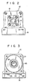
- Fig. 2 shows the right side end of the first embodiment shown in Fig. 1.
- Fig. 3 is a sectional view taken along the line 3-3 in Fig. 1.
- Fig. 4 shows how the solenoid and permanent magnet act.
- Fig. 5 is a longitudinally-sectioned view showing a second embodiment of an electromagnetic oscillation pump according to the present invention.
- Figs. 1 through 4 show a first embodiment of an electromagnetic oscillation pump according to the present invention, in which a
pump 10 has anend member 12 provided with aninlet 11 and connected to anexternal pipe 15 shown by a two-dot and dash line in Fig. 1, and anotherend member 14 provided with anoutlet 13 and connected to anexternal pipe 16 shown by a two-dot and dash line in Fig. 1. Liquid such as water and medical liquid is fed from a tank (not shown) into theinlet 11 through thepipe 15 as shown by an arrow A and discharged through theoutlet 13 into thepipe 16 in a direction shown by an arrow B to be used at an appropriate section (not shown). Theend members plural bolts rectangular frames casing 21 is sandwiched between these frames and fixed integral to theframe 18 by thebolts 20. Theseend members frames casing 21 form a pump framework. -
End portions member 22 are fixed to theframes frames member 22 are communicated with theinlet 11 andoutlet 13, respectively. Therefore, liquid to be fed through the pump flows through the oscillatingmember 22 along anaxial line 25 shown by a dot and dash line in Fig. 1. The oscillatingmember 22 has a pair ofexpansible portions 26 and 27 continuous from its end portions, and anintermediate portion 28 between these expansible portions. The oscillatingmember 22 is made integral of a resilient material such as rubber. Theexpansible portions 26 and 27 are formed in bellows shape in the case of this embodiment and the expanding and contracting movement of these expansible portions along theaxial line 25 causes theintermediate portion 28 to be oscillated in the direction ofaxial line 25. The oscillatingmember 22 is symmetrical on both sides of the center of saidintermediate portion 28, which is positioned in the center of the pump or pump framework. - The pump framework is supported by a
floating support plate 30, which is attached to the pump framework by means ofscrews 29 and suspended at both ends thereof bysprings 32 from afixed base plate 31. Therefore, the oscillation of the operating pump is absorbed by thesprings 32 and not transmitted directly to thebase plate 31. - A
valve 33 made of same material as that of theintermediate portion 28 is arranged inside theintermediate portion 28 of said oscillating member and made integral to theintermediate portion 28 at itsaxial portion 33a, with itswing portion 33b usually press-contacted with the inner circumferential wall of theintermediate portion 28 to stop the flow of liquid. When liquid pressure becomes different on both sides of thevalve 33 or higher on the upper or left side of thevalve 33 in Fig. 1, however, thewing portion 33b is resiliently deformed as shown by a two-dot and dash line, allowing liquid to flow. Thisvalve 33 is moved integral to theintermediate portion 28 and will be hereinafter referred to as movable valve. - A sleeve- or cylinder-
shaped armature 35 is fixed around the outer circumference of theintermediate portion 28 and along the whole length thereof. The armature is therefore moved integral to theintermediate portion 28 and will be hereinafter referred to as movable armature. - A
solenoid 36 is arranged concentric with the armature and in the center of the framework, enclosing themovable armature 35. Thesolenoid 36 is connected through aline 37 to a commercially available external AC power supply (not shown), and a half-wave rectifier ordiode 38 is arranged to another line. Since direct current half-wave-rectified is therefore supplied to thesolenoid 36, thearmature 35 is drawn along theaxial line 25 only in one direction (or in the right or liquid-flowing direction in Fig. 1) when the solenoid is excited, thus enabling so-called electromagnetic drive of DC solenoid type to be achieved. When thesolenoid 36 is excited, effective drawing force is caused particularly between thearmature 35 and aslanted surface 39a formed on ayoke 39 for the solenoid. Anotheryoke 40 for thesolenoid 36 is formed in L-shape to guide thearmature 35 in the axial direction and provided with anauxiliary guide 41. - A
valve 42 having same construction as that of themovable valve 33 is arranged inside theend member 14 positioned on the side of theoutlet 13. This is a fixed valve not movable in the axial direction but cooperative with themovable valve 33 to define a pumping chamber therebetween and to forcedly feed liquid, thus enabling a pump of self-supply type to be formed. - A
permanent magnet 43 is arranged in the framework along the axial line and adjacent to thesolenoid 36. Thismagnet 43 is ring- or cylinder-shaped as shown in Fig. 3 and arranged concentric with and around themovable armature 35. Themagnet 43 has a pair of left andright yokes yoke 40 is common to thesolenoid 36. This is made possible by juxtaposing themagnet 43 with thesolenoid 36 on one side thereof without any clearance interposed therebetween. However, it may be arranged as a variation that thepermanent magnet 43 is separated a little from thesolenoid 36 and has a pair of its exclusive yokes. - The
permanent magnet 43 serves to return thearmature 35 from its driven position to its original position shown in Fig. 1 after the armature is drawn and driven by the electromagnetic force of thesolenoid 36. Themagnet 43 therefore makes it unnecessary to employ the conventional mechanical return spring. The drawing force with which thearmature 35 is drawn by thesolenoid 36 is set to have a practical value about twice that of the permanent magnet, and the drawing force of the solenoid can be therefore obtained as desired even if the drawing force of thepermanent magnet 43 usually acts on thearmature 35. - Practically, the drawing and driving action of the
solenoid 36 and the drawing and returning action of thepermanent magnet 43 are alternately acted on thearmature 35, thus enabling thearmature 35 to be oscillated together with theintermediate portion 28 at high speed along the axial direction. Themovable valve 33 is also cooperated at the same time to pump liquid out of the pumping chamber defined between the movable andfixed valves - Fig. 4 shows the directions in which the
armature 35 is drawn by thesolenoid 36 andpermanent magnet 43 and the directions in which theirlines solenoid 36 is excited generates a strongest flux between both ofyokes dash lines 47 between both ofyokes permanent magnet 43 andyoke 44 are magnetic materials and effect same action as that of the solenoid yokes. In addition, the direction of the leaking fluxes is reverse to the direction in which theline 46 of magnetic force of thepermanent magnet 43 is directed. Namely, when thesolenoid 36 effects its drawing and driving force, the magnetic energy of thepermanent magnet 43 with which the drawing force is generated in the direction D is reduced by that of the leaking fluxes of thesolenoid 36. This is a preferable effect but can be achieved in the case under which the magnetic pole of thepermanent magnet 43 is arranged as shown in Fig. 4. - As described above, the reduction of drawing and driving force of the solenoid because of reversely directed drawing force of the permanent magnet can be made small when the solenoid effects its drawing and driving force, but all of drawing force of the
permanent magnet 43 can be acted on the armature when it is returned from its driven position. This is an extremely desirable effect. Fig. 4 is a sectional view but hatching in each of parts is omitted for the clarity of description. - A second embodiment of electromagnetic oscillation pump according to the present invention and shown in Fig. 5 is same in fundamental construction as the first one. Therefore, each of its parts is represented by a reference numeral expressed by adding one hundred to its corresponding original numeral and detailed description on these parts will be omitted.
- In the case of this second embodiment of a
pump 110, a pipe-like oscillatingmember 122 has diaphragms which serve as a pair ofexpansible portions end portions expansible portions expansible portions 26 and 27, and this is suitable for a pump whose length is shortened. - A
movable valve 133 is arranged inside an intermediate portion 128 and to one side thereof. A fixedvalve 142 is arranged inside anend member 114 and opposite to themovable valve 133. A sleeve-shaped movable armature 135 fixed around the intermediate portion corresponds to asolenoid 136 and apermanent magnet 143 arranged concentric with and around the armature 135. Thepermanent magnet 143 uses its drawing force to return the armature 135, which has been drawn and driven by the solenoid, from its driven position to its original position shown in Fig. 5. The conventional mechanical return spring is therefore made unnecessary. Same thing as in the first embodiment can be said about the positional relation between thesolenoid 136 andpermanent magnet 143 and the action of their electromagnetic and magnetic forces. - As described above, any of embodiments according to the present invention allows the armature to be returned not by the conventional mechanical spring but by the drawing force of the permanent magnet. Since no member such as the spring which may break because of its fatigue when the oscillating member is oscillated at high speed is used, the durability and reliability of the pump can be enhanced. In addition, it is made unnecessary to design the complicated attaching portions of the spring and to do the troublesome work of attaching it. Further, the whole of the pump can be easily smaller-sized and the problem of corrosion can be solved substantially even if the pump is used under specific atmosphere because no spring is employed as movable mechanical part. As apparent from the above, the present invention can provide an electromagnetic oscillation pump capable of achieving various excellent effects.
- It should be understood that the present invention is not limited to the above-described embodiments. The permanent magnet may not be connected or arranged adjacent to the solenoid and is not limited to those of ring-shaped or annular type.
Claims (7)
1. An electromagnetic oscillation pump comprising a pump framework (12, 14, 17, 18; 112, 114, 117, 118) having an inlet (11, 111) and an outlet (13, 113), a pipe-like oscillating member (22, 122) supported at both ends thereof by said framework and having a pair of expansible portions (26, 27; 126, 127) and an intermediate portion (28, 128) between said expansible portions and oscillated along an axial line (25) in cooperation with the expanding and contracting movement of said expansible portions to feed a liquid therethrough, a movable valve (33, 133) supported inside the intermediate portion and movable with the intermediate portion, a movable armature (35, 135) fixed around the intermediate portion and movable with the intermediate portion between an original position and a driven position, a solenoid (36, 136) arranged in the framework enclosing the armature and exerting its electromagnetic force to draw and drive the armature together with the intermediate portion from the original position to the driven position in a direction along the axial line, characterized in that a permanent magnet (43, 143) is arranged in the framework (12, 14, 17, 18; 112, 114, 117, 118) in a manner to correspond to the armature (35, 135) thereby to return by the drawing force of the permanent magnet the solenoid-driven armature from the driven position to the original position along the axial line (25).
2. An electromagnetic oscillation pump according to claim 1, wherein said permanent magnet (43, 143) is arranged adjacent to the solenoid (36, 136) and to one side thereof along the axial line.
3. An electromagnetic oscillation pump according to claim 2, wherein said permanent magnet (43, 143) has a pair of yokes (39, 40; 139, 140) for sandwiching the permanent magnet from both sides thereof, and one (40, 140) of said yokes is commonly used as one of paired yokes (40, 44; 140, 144) for the solenoid.
4. An electromagnetic oscillation pump according to any of claims 1, 2 and 3, wherein said permanent magnet (43, 143) is ring-shaped to enclose the armature (35, 135).
5. An electromagnetic oscillation pump according to claim 1, further comprising a fixed valve (42, 142) disposed remote from the movable valve (33, 133).
6. An electromagnetic oscillation pump according to claim 1, wherein the expansible portions (26, 27) of said oscillating member (22) are bellows-shaped.
7. An electromagnetic oscillation pump according to claim 1, wherein the expansible portions (126, 127) of said oscillating member (122) are diaphragm-shaped.
Applications Claiming Priority (2)
| Application Number | Priority Date | Filing Date | Title |
|---|---|---|---|
| JP45780/81 | 1981-03-28 | ||
| JP4578081A JPS57159971A (en) | 1981-03-28 | 1981-03-28 | Electromagnetic reciprocal pump |
Publications (1)
| Publication Number | Publication Date |
|---|---|
| EP0061699A1 true EP0061699A1 (en) | 1982-10-06 |
Family
ID=12728797
Family Applications (1)
| Application Number | Title | Priority Date | Filing Date |
|---|---|---|---|
| EP82102402A Withdrawn EP0061699A1 (en) | 1981-03-28 | 1982-03-23 | Electromagnetic oscillation pump |
Country Status (2)
| Country | Link |
|---|---|
| EP (1) | EP0061699A1 (en) |
| JP (1) | JPS57159971A (en) |
Cited By (4)
| Publication number | Priority date | Publication date | Assignee | Title |
|---|---|---|---|---|
| EP0110117A2 (en) * | 1982-11-26 | 1984-06-13 | Cordis Corporation | Implantable microinfusion pump system |
| DE102017203464A1 (en) | 2017-03-02 | 2018-09-06 | BSH Hausgeräte GmbH | Oscillating piston pump with valve arrangement |
| DE102018003507B3 (en) | 2018-04-28 | 2019-10-24 | Thomas Magnete Gmbh | Linear-acting electric pump unit with a bellows and method of operating the same |
| US11302468B2 (en) | 2018-04-28 | 2022-04-12 | Thomas Magnete Gmbh | Electromagnet and method to produce the electromagnet |
Families Citing this family (1)
| Publication number | Priority date | Publication date | Assignee | Title |
|---|---|---|---|---|
| JPS6157175U (en) * | 1984-09-19 | 1986-04-17 |
Citations (3)
| Publication number | Priority date | Publication date | Assignee | Title |
|---|---|---|---|---|
| US3136257A (en) * | 1961-10-26 | 1964-06-09 | Gorman Rupp Ind Inc | Oscillating pump impeller |
| AT252736B (en) * | 1963-11-29 | 1967-03-10 | Elektro App Werke Veb | Electromagnetic oscillating piston pump |
| US3756750A (en) * | 1971-07-20 | 1973-09-04 | Mattel Inc | Reciprocating valveless pump |
-
1981
- 1981-03-28 JP JP4578081A patent/JPS57159971A/en active Pending
-
1982
- 1982-03-23 EP EP82102402A patent/EP0061699A1/en not_active Withdrawn
Patent Citations (3)
| Publication number | Priority date | Publication date | Assignee | Title |
|---|---|---|---|---|
| US3136257A (en) * | 1961-10-26 | 1964-06-09 | Gorman Rupp Ind Inc | Oscillating pump impeller |
| AT252736B (en) * | 1963-11-29 | 1967-03-10 | Elektro App Werke Veb | Electromagnetic oscillating piston pump |
| US3756750A (en) * | 1971-07-20 | 1973-09-04 | Mattel Inc | Reciprocating valveless pump |
Cited By (6)
| Publication number | Priority date | Publication date | Assignee | Title |
|---|---|---|---|---|
| EP0110117A2 (en) * | 1982-11-26 | 1984-06-13 | Cordis Corporation | Implantable microinfusion pump system |
| EP0110117A3 (en) * | 1982-11-26 | 1984-09-26 | Cordis Corporation | Implantable microinfusion pump system |
| DE102017203464A1 (en) | 2017-03-02 | 2018-09-06 | BSH Hausgeräte GmbH | Oscillating piston pump with valve arrangement |
| DE102018003507B3 (en) | 2018-04-28 | 2019-10-24 | Thomas Magnete Gmbh | Linear-acting electric pump unit with a bellows and method of operating the same |
| US11302468B2 (en) | 2018-04-28 | 2022-04-12 | Thomas Magnete Gmbh | Electromagnet and method to produce the electromagnet |
| US11512682B2 (en) | 2018-04-28 | 2022-11-29 | Thomas Magnete Gmbh | Linear-acting electric pump unit and method for operating said unit |
Also Published As
| Publication number | Publication date |
|---|---|
| JPS57159971A (en) | 1982-10-02 |
Similar Documents
| Publication | Publication Date | Title |
|---|---|---|
| US6659740B2 (en) | Vibrating membrane fluid circulator | |
| US4585397A (en) | Dual bellows pump with drive circuit through bellows | |
| CN100373074C (en) | Active vibration damping device | |
| US5231337A (en) | Vibratory acoustic compressor | |
| JP2004056850A (en) | Linear actuator, and pump device or compressor device using the actuator | |
| EP0061699A1 (en) | Electromagnetic oscillation pump | |
| EP0014817A1 (en) | Electro-magnetic fluid pump | |
| US11791702B2 (en) | Electric motor with stator and mobile armature with suspending leaf springs which prevent movement in transverse direction and is in airgap plane that is perpendicular to first loop plane | |
| KR940006861B1 (en) | Electromagnetic pump | |
| EP3289259B2 (en) | Low profile miniature solenoid proportional valve | |
| US4370107A (en) | Spring biased fluid pump | |
| US7665510B2 (en) | Fluid drive unit and heat transport system | |
| KR940000808Y1 (en) | Diaphram pump | |
| US10731464B2 (en) | Linear actuator and method for operating such a linear actuator | |
| US2838007A (en) | Agitating device | |
| JP2009532011A (en) | Electromagnetic converter | |
| JPS58110871A (en) | Pump of solenoid drive | |
| JPH07167327A (en) | Displacement enlarging mechanism for actuator | |
| CN218294450U (en) | Cage type giant magnetostrictive proportional valve | |
| WO2017038146A1 (en) | Electromagnetic pump | |
| JP3005780U (en) | Vibration pump | |
| JP2006342711A (en) | Fluid pump | |
| JP3004918U (en) | Vibration pump | |
| JPH0472478A (en) | Oscillatory type pump | |
| JP2941267B2 (en) | Compressor |
Legal Events
| Date | Code | Title | Description |
|---|---|---|---|
| PUAI | Public reference made under article 153(3) epc to a published international application that has entered the european phase |
Free format text: ORIGINAL CODE: 0009012 |
|
| 17P | Request for examination filed |
Effective date: 19820323 |
|
| AK | Designated contracting states |
Designated state(s): DE FR GB IT |
|
| STAA | Information on the status of an ep patent application or granted ep patent |
Free format text: STATUS: THE APPLICATION IS DEEMED TO BE WITHDRAWN |
|
| 18D | Application deemed to be withdrawn |
Effective date: 19840410 |
|
| RIN1 | Information on inventor provided before grant (corrected) |
Inventor name: MIYAZAKI, MASAHITO Inventor name: FUJINAKA, YOSHIAKI Inventor name: CHIBA, YOSHII Inventor name: KUWABARA, FUKUZI |