EP0061906A1 - A method of, and an apparatus for, processing a workpiece with energetic particles and a product processed thereby - Google Patents
A method of, and an apparatus for, processing a workpiece with energetic particles and a product processed thereby Download PDFInfo
- Publication number
- EP0061906A1 EP0061906A1 EP82301592A EP82301592A EP0061906A1 EP 0061906 A1 EP0061906 A1 EP 0061906A1 EP 82301592 A EP82301592 A EP 82301592A EP 82301592 A EP82301592 A EP 82301592A EP 0061906 A1 EP0061906 A1 EP 0061906A1
- Authority
- EP
- European Patent Office
- Prior art keywords
- particles
- workpiece
- beams
- ions
- energetic
- Prior art date
- Legal status (The legal status is an assumption and is not a legal conclusion. Google has not performed a legal analysis and makes no representation as to the accuracy of the status listed.)
- Granted
Links
Images

Classifications
-
- H—ELECTRICITY
- H01—ELECTRIC ELEMENTS
- H01J—ELECTRIC DISCHARGE TUBES OR DISCHARGE LAMPS
- H01J37/00—Discharge tubes with provision for introducing objects or material to be exposed to the discharge, e.g. for the purpose of examination or processing thereof
- H01J37/32—Gas-filled discharge tubes
- H01J37/32431—Constructional details of the reactor
-
- C—CHEMISTRY; METALLURGY
- C23—COATING METALLIC MATERIAL; COATING MATERIAL WITH METALLIC MATERIAL; CHEMICAL SURFACE TREATMENT; DIFFUSION TREATMENT OF METALLIC MATERIAL; COATING BY VACUUM EVAPORATION, BY SPUTTERING, BY ION IMPLANTATION OR BY CHEMICAL VAPOUR DEPOSITION, IN GENERAL; INHIBITING CORROSION OF METALLIC MATERIAL OR INCRUSTATION IN GENERAL
- C23C—COATING METALLIC MATERIAL; COATING MATERIAL WITH METALLIC MATERIAL; SURFACE TREATMENT OF METALLIC MATERIAL BY DIFFUSION INTO THE SURFACE, BY CHEMICAL CONVERSION OR SUBSTITUTION; COATING BY VACUUM EVAPORATION, BY SPUTTERING, BY ION IMPLANTATION OR BY CHEMICAL VAPOUR DEPOSITION, IN GENERAL
- C23C14/00—Coating by vacuum evaporation, by sputtering or by ion implantation of the coating forming material
- C23C14/22—Coating by vacuum evaporation, by sputtering or by ion implantation of the coating forming material characterised by the process of coating
- C23C14/221—Ion beam deposition
-
- C—CHEMISTRY; METALLURGY
- C23—COATING METALLIC MATERIAL; COATING MATERIAL WITH METALLIC MATERIAL; CHEMICAL SURFACE TREATMENT; DIFFUSION TREATMENT OF METALLIC MATERIAL; COATING BY VACUUM EVAPORATION, BY SPUTTERING, BY ION IMPLANTATION OR BY CHEMICAL VAPOUR DEPOSITION, IN GENERAL; INHIBITING CORROSION OF METALLIC MATERIAL OR INCRUSTATION IN GENERAL
- C23C—COATING METALLIC MATERIAL; COATING MATERIAL WITH METALLIC MATERIAL; SURFACE TREATMENT OF METALLIC MATERIAL BY DIFFUSION INTO THE SURFACE, BY CHEMICAL CONVERSION OR SUBSTITUTION; COATING BY VACUUM EVAPORATION, BY SPUTTERING, BY ION IMPLANTATION OR BY CHEMICAL VAPOUR DEPOSITION, IN GENERAL
- C23C14/00—Coating by vacuum evaporation, by sputtering or by ion implantation of the coating forming material
- C23C14/22—Coating by vacuum evaporation, by sputtering or by ion implantation of the coating forming material characterised by the process of coating
- C23C14/48—Ion implantation
-
- C—CHEMISTRY; METALLURGY
- C23—COATING METALLIC MATERIAL; COATING MATERIAL WITH METALLIC MATERIAL; CHEMICAL SURFACE TREATMENT; DIFFUSION TREATMENT OF METALLIC MATERIAL; COATING BY VACUUM EVAPORATION, BY SPUTTERING, BY ION IMPLANTATION OR BY CHEMICAL VAPOUR DEPOSITION, IN GENERAL; INHIBITING CORROSION OF METALLIC MATERIAL OR INCRUSTATION IN GENERAL
- C23C—COATING METALLIC MATERIAL; COATING MATERIAL WITH METALLIC MATERIAL; SURFACE TREATMENT OF METALLIC MATERIAL BY DIFFUSION INTO THE SURFACE, BY CHEMICAL CONVERSION OR SUBSTITUTION; COATING BY VACUUM EVAPORATION, BY SPUTTERING, BY ION IMPLANTATION OR BY CHEMICAL VAPOUR DEPOSITION, IN GENERAL
- C23C8/00—Solid state diffusion of only non-metal elements into metallic material surfaces; Chemical surface treatment of metallic material by reaction of the surface with a reactive gas, leaving reaction products of surface material in the coating, e.g. conversion coatings, passivation of metals
- C23C8/06—Solid state diffusion of only non-metal elements into metallic material surfaces; Chemical surface treatment of metallic material by reaction of the surface with a reactive gas, leaving reaction products of surface material in the coating, e.g. conversion coatings, passivation of metals using gases
- C23C8/36—Solid state diffusion of only non-metal elements into metallic material surfaces; Chemical surface treatment of metallic material by reaction of the surface with a reactive gas, leaving reaction products of surface material in the coating, e.g. conversion coatings, passivation of metals using gases using ionised gases, e.g. ionitriding
-
- C—CHEMISTRY; METALLURGY
- C30—CRYSTAL GROWTH
- C30B—SINGLE-CRYSTAL GROWTH; UNIDIRECTIONAL SOLIDIFICATION OF EUTECTIC MATERIAL OR UNIDIRECTIONAL DEMIXING OF EUTECTOID MATERIAL; REFINING BY ZONE-MELTING OF MATERIAL; PRODUCTION OF A HOMOGENEOUS POLYCRYSTALLINE MATERIAL WITH DEFINED STRUCTURE; SINGLE CRYSTALS OR HOMOGENEOUS POLYCRYSTALLINE MATERIAL WITH DEFINED STRUCTURE; AFTER-TREATMENT OF SINGLE CRYSTALS OR A HOMOGENEOUS POLYCRYSTALLINE MATERIAL WITH DEFINED STRUCTURE; APPARATUS THEREFOR
- C30B33/00—After-treatment of single crystals or homogeneous polycrystalline material with defined structure
Definitions
- the present invention relates to a method of, and an apparatus for, processing a workpiece with energetic particles, especially energetic ions.
- the invention is applicable to ion plating in which energetic ions impinging on a workpiece surface are deposited thereon, ion-implantation in which energetic ions impinging upon a workpiece are diffused into the workpiece substrate and ion-etching or milling in which material of the workpiece is removed by energetic ion bombardment, all of which are generally referred to herein as energetic ion processing.
- the invention is also applicable to the treatment of a workpiece surface with energetic non-charged or neutral particles, such as atoms or molecules,and thus should be considered to broadly relate to energetic particle processing.
- Another important object of the invention is to provide an energetic particle processing method whereby a new and useful material or material structure can be obtained.
- a further object of the invention is to provide a novel and highly versatile apparatus for processing a workpiece with energetic particles of atomic or molecular size, which is relatively simple in structure and easy to operate.
- a method of processing a workpiece with energetic particles of atomic or molecular size comprises disposing the workpiece in with/an evacuation chamber; providing a plurality of sources of such particles of predetermined different substances and arranging the sources within respective receptacles so that each of the receptacles is in vacuum communication with the evacuation chamber and open towards the workpiece; forming the particles of the respective substances from the corresponding sources within the respective receptacles; and extracting the formed particles of the respective substances from the respective cham- beams bers in the form of respective particle/(fluxes) directed towards the workpiece and energizing the extracted particles in the res- beams pective of the different substances to propel with respective magnitudes of kinetic energy to bombard the workpiece jointly therewith in the evacuation chamber.
- the particle comprise beams of ions of different substances and may include at least beam one of neutral particles of a different substance.
- two particle beams may be used, one being a beam of energetic ions of a first substance and the other being a beam of energetic neutral or non-charged particles, e.g. atoms, of a second.substance..
- the two beams may be applied alternately or simultaneously to the workpiece for alternate or simultaneous impingement thereon.
- one or more particle beams be pulsed to provide a cluster of energetic ions and/or energetic neutral particles for impingement upon the workpiece.
- Repetitive pulsing provides a succession of clusters of energetic ions and/or energetic neutral particles for simultaneous or alternate beams impingement upon the workpiece.
- Two or more may be fo- beam cused to form a composite or cluster in which ions and/or neutral particles of difference substance are mixed together with a predetermined ratio of their numbers in the continuous beam or in the cluster, prior to impingement upon the workpiece.
- the invention also provides, in a second aspect thereof, an apparatus for processing a workpiece with energetic particles of atomic or molecular size, which apparatus comprises: an evacuation chamber; support means for supporting the workpiece within the evacuation chamber; a plurality of sources of such particles of predetermined different substances, each source being held within an individual receptacle which is in a vacuum communication with the chamber; a plurality of particle gererat- ing means associated with the plural sources, respectively, for forming the particles of the respective substances from the corresponding sources within the receptacles, respectively; a plurality of energy supply means associated with the plural receptacles, respectively., for withdrawing the formed particles of the respective substances therefrom in the form of respective particle beams directed towards the workpiece and energizing the respective beams to propel with respective magnitudes of kinetic energy for a joint bombardment of the workpiece.
- Each of the plural or of more than one generating means may comprise an ion chamber for forming ions.
- the ions formed in the ion chamber are extracted and energized towards the work- t piece by applying an acceleration polential thereto which is preferably-pulsed repetitively to form a succession of clusters of energetic ions.
- Neutral particles may be formed within a receptacle by applying an energy beam upon the particle source to knock out the atoms therefrom. The neutral particles are beam ejected from the receptacle and shaped into a by applying a vacuum to the particles by means of, say, a cryogenic pump.
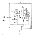
- the apparatus shown includes an evacuation chamber 1 in which a workpiece 2 is securely mounted on a rotary table 3.
- the latter is rotatable by a motor(not shown).
- the chamber 1 is hermetically sealed and provided with a duct 4 which communicates with a vacuum pump(not shown)for maintaining the space in the chamber 1 at a high vacuum ranging between 10 -6 and 10 -4 Torr ( ⁇ 1.33x10 -4 Pa and 1.33x10 -2 Pa).
- the rotary table 3 is rotated to displace the workpiece 2 to subject successive surface areas thereof to impingement of energetic particles as will be described. It will be apparent that a plurality of workpieces may be carried on the rotary table 3 for successive processing.
- heads 5 and 6 are shown and are oriented towards the workpiece 2.
- the two heads 5 and 6 may radi- ate beams 7 and 8 of energized ions of different substances jointly upon the workpiece 2.
- the head 5 may radiate a beam 7 of energized ions of one substance and the head 6 may radiate a beam 8 of energized neutral particles, e.g. atoms, of another substance, the two beams impinging jointly upon the workpiece 2.
- a cryogenic pump 9, commonly also called cryopump is shown provided midway between the head 6 and the workpiece 2.
- the cryopump 9 which may employ liquid nitrogen as its operat- ing fluid, is used to extract the neutral particles formed in the head 6 and to focus and shape them into a beam 8 for impingement upon the workpiece 2.
- the ion beam generating head 5 is provided at its outlet opening 10 with an electrode 11 connected via a switch 12 to one terminal (positive) of a voltage supply 13 whose other terminal (negative) is electrically connected to the workpiece 2 via the disk and the shaft of the rotary table 3 as shown.
- the voltage supply 13 has an output voltage ranging between 500 volts and 5 kilovolts sufficient to extract the ions formed in the head 5 and to accelerate and shape them into a beam 7 for impingement upon the workpiece 2-.
- the other head 6 is constituted as an ion beam generator, like the head 5, its opening 14 should, of course, be provided with an electrode 15 connected via a switch 16 to the positive terminal of the voltage supply 13 as shown by the phantom line.
- a lens system 17 is also provided, comprising a first pair of electrodes 18 and a second pair of electrodes 19 across the paths of the beams 7 and 8 midway between the head 5 and 6and the workpiece 2 to focus the beams 7 and 8 into a unitary composite beam in which the energetic particles in the beam 7 and the energetic particles in the beam 8 are mixed together prior to impingement upon the workpiece 2.
- the first pair of the focusing electrodes 17 are juxtaposed with each other in a given direction whereas the other pair of focusing electrodes 18 are juxtaposed with each other in a horizontal direction orthogonal to that direction.
- the electrodes 18 and the electrodes 19 are both energized by a high-frequency AC voltage source 20. It will be apparent that any other beam- focusing lens system may be employed such as an electromagnetic coil arranged to surround the paths of the beams 7 and 8 and energized bythe high-frequency AC voltage source 20.
- the head 5 for generating ions may, as shown in FIG. 3, comprise an anode 21 which constitutes a source of the ions.
- the anode 21 is spacedly juxtaposed with a cathode filament 22 within an evacuated receptacle 23.
- the latter has a duct 24 which communicates with a vacuum pump or. a fluid supply(not shown)to maintain the space within the receptacle 23 at a pressure ranging between 10 -3 and 10 Torr ( ⁇ 0.1333 Pa and 1333 Pa).
- the cathod filament.22 is heated by an AC supply 25 and also connected to the negative terminal of a DC voltage supply 26 whose positive terminal is connected to the anode 21.
- the DC voltage supply 26 is used to produce an electrical discharge between the anode 21 and the cathode 22, thereby producing ions from the anode 21.
- the voltage supply 26 should preferably be designed to provide a pulsed voltage or a succession of voltage pulses.
- the pulse duration of the voltage pulses should preferably range between 0.5 and 10 microseconds.
- the gas should then be composed, of course, of a predetermined substance of which are desired the ions for processing the workpiece 2.
- the ions formed within the receptacle 23 are withdrawn therefrom through the outlet opening 10 and shaped into a beam 7 as shown in FIG. 1.
- FIG. 4 shows an embodiment of the head 6 as contructed to form neutral particles of a desired substance.
- This embodiment employs a source of the particles shown in the form of a plate 27 placed within a receptacle 28.
- the latter is formed with a duct 29 which communicates with a vacuum pump or fluid supply(not shown)to maintain the space within the. receptacle 28 at a pressure ranging between 10 -6 and 10 -2 Torr. ( ⁇ 1.33x10⁻⁴Pa and 1.33 Pa)
- a source 30 of an energy beam is constituted by an ion gun which projects an ion beam into the receptacle 28 to apply it upon the plate 27, thereby'evaporating or knocking out atoms constituting the plate 27.
- the latter is positioned to direct the atoms liberated from the plate 27 towards the workpiece 2 through an outlet opening 31 of the receptacle 28.
- the ion acceleration voltage ranging between 1 and 5 kilovolts and applied from a voltage supply 32 between the gun 30 and the plate 27 should preferably be pulsed or in the form of voltage pulses.
- the pulse duration should preferably range between 0.5 and 10 microseconds.
- the heads 5 and 6 need not be disposed within the evacuation chamber 1 and may instead be arranged outside thereof. It is only necessary that the receptacles 23 and 28 communicate with the chamber 1 through the outlets 10 and 31, respectively.
- the ion beam 7 is projected from the head 5 to propel in a high vacuum of 10 -6 .to 10 -4 Torr ( ⁇ 1.33 x 10 -4 Pa and 1.33 x 10 -2 Pa) within the chamber 1 for impingement upon the workpiece 2.
- the impact energy of the ion beam 7 impinging on the workpiece 2 is controlled by the acceleration voltage applied by the voltage source 13.
- the power supply 26 provides a pulsed voltage. The number of ions in each cluster may be preset by presetting the pulse duration of the pulsed voltage furnished by the voltage supply 26.
- the pulse duration may range between 0.5 and 10 microseconds to provide a cluster having ions grouped therein ranging between 100 and 1000 in number.
- An acceleration voltage ranging between 500 and 5000 volts is applied to a cluster of ions 7 to cause them to impinge upon the workpiece 2.
- a cluster of ions may also be produced by turning on and off the switch 16 connecting the acceleration voltage supply 13 to the electrode 11.
- the neutral particle beam 8 may be applied, simulta- neously or alternately with the ion beam 7, to the workpiece 2.
- the source plate 27 is bombarded with an energy beam of ions from the gun 30 and is thereby evaporated to furnish the neutral particles.
- a cluster of the neutral particles is obtained by pulsing the output voltage of the supply 32.
- An isentropic expansion and overcooling process is then applied.
- the number of neutral particles is regulated by adjusting the pulse duration of the pulsed acceleration voltage applied by the voltage supply 32 across the gun 30 and the evaporation source 27.
- the ion gun may be replaced by a laser beam gun.
- a cluster of neutral particles which develops pulsively is projected pulsively into the evacuation chamber 1 from the head 6.
- the ion beam 7, either continuous or clustered, is,'while being accelerated, focused by the lens system 17 for impingement upon the workpiece 2.
- the neutral particle beam 8, either continuous or clustered, is accelerated and focused by the cryopump 9 for beam impingement upon the workpiece 2.
- the ions in the beam 7 impinge upon the workpiece 2 with a predetermined magnitude of kinetic energy preset by the acceleration voltage source 13.
- the neu- tral particles in the beam 8 impinge upon the workpiece 2 with a predetermined magnitude of kinetic energy derived from their rate of projection from the head 6 and preset by the cryopump 9.
- the proportion in number of ions and neutral particles impinging upon the workpiece 2 continuously, or synchronously in a cluster I or nonsynchronously in clusters is regulated by adjusting the voltage supply 26 and the voltage supply 32.
- the mass to charge ratio of the composite energetic particles can likewise be preset.
- the plate 27 in the head 6 may be composed of a metal which is desired to be deposited upon the workpiece 2.
- the head 5 may furnish ions of a material which it is desirable to chemically combine with the metal.
- the metal ions in the beam 7 and the reactant neutral particles in the beam 8 are directed in the arrangement shown to impinge jointly on the workpiece 2 and are then allowed, through their mutual interaction, to exchange electrical energy and to chemically react.
- a physical impact pressure is brought about and facilitate diffusion of materials of the plated layer into the substrate of the workpiece 2 while the density of the plated layer and its strength of adhesion to the substrate.
- a nitrided, carbided, fluorided or sulfided layer of deposition of an excellent quality and high hardness and/or corrosion resistance is obtainable.
- the energetic particles impinging in succession hold the workpiece surface in a highly activated state.
- a slight portion of neutral particles will, as a result of collision with energetic ions, be ionized to facilitate growth of the plated layer and increase of its thickness and to enhance the rate of deposition.
- the neutral particles when clustered can readily be accelerated with energetic ions under a high-potential electric field. An increase in the rate of deposition and an enhancement of the properties of the plating film are obtainable in this manner.
- beam Ion plating or deposition exploits a beam of energetic ions having kinetic energy ranging between 1 and 1000 eV.
- the kinetic energy may be increased to a range of 10 4 to 10 6 eV to allow ion implantation.
- a glass plate may be beam keV beam etched with a beam of oxygen ions energized at 1 Kex.
- a flux of fluorine neutral particles is added to achieve a rate of (40nm/min) etching as high as 400 angstroms/min/.
- the glass surface having (5 to 10nm) cracks of 50 to 100 angstromsLin depth is processed for a period of 25 seconds to remove the cracks 2
- the strength of glass is (kgf/cm ) increased to more than 200 kg/cm/, approximately 10 times stronger than the unprocessed glass plate.
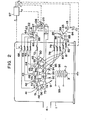
- FIG. 2 in which same referece numerals as in FIG. 1 are used to designate essentially same components, five ener- beam getic particle beam generating units 41, 42, 43, 44 and 45 are shown as disposed within the evacuation chamber 1 and as oriented towards a workpiece 2 supported on a work holder 3 which may again be a rotary table. All units 41 - 45 are shown as ion beam beam generators but one or more of the units 41 - 45 may be a neutral particle generator as shown in FIGS. 1 and 4. As already indicated the units need not be disposed within the chamber 1, but may instead be arranged outside thereof.
- Each unit 41, 42, 43, 44, 45 comprises a receptacle 46, 47, 48, 49, 50 in which an anode 51, 52, 53, 54, 55 and a filament cathode 56, 57, 58, 59, 60 are spacedly juxtaposed with each other as already described.
- the anodes 51 - 55 may provide the respective sources of different substances of which are desired ions as discribed earlier.
- the cathodes 56 - 60 are heated by a common AC supply 125 and are also connected to the negative terminal of a common DC voltage supply 126 whose p osi- tive terminal is connected to a rotary contact 61 of a rotary switch 62.
- the latter has five fixed contacts 63, 64, 65, 66 and 67 which are connected to the anodes 51, 52, 53, 54 and 55 via resistors 68, 69, 70, 71 and 72, respectively.
- the rotary contact 61 turns to engage with the fixed contacts 63 - 67 successively, the anodes and cathodes 51 and 56, 52 and 57, 53 and 58, 54 and 59 and 55 and 60 are energized successively.
- anode and the cathode in each generator 41, 42, 43, 44, 45 are energized, an electrical discharge develops between them.
- the anode is bombarded with electrons emitted from the cathode to liberate positive ions of the anode substance within each receptacle 46, 47, 48, 49, 50.
- the anodes 51 - 55 are composed of preselected different substances; ions of these different substances are formed in the receptacles 46 - 50 in a predetermined time sequence as the rotary switch 62 rotates.
- the resistors 68 - 72 are adjustably preset to variably set up the respective ion-forming voltages across the anode and the cathode in the respective receptacles 46 - 50.
- these voltages thus determine the quantity (number) of ions and the quantity (number) of charges produced in each receptacle 51, 52, 53, 54, 55.
- the voltage supply 126 may furnish a pulsed voltage or a succession of voltage pulses with a pulse duration between 0.5 and 10 microseconds'so that while the rotary contact 61 is in engagement with each fixed contact 63, 64, 65, 66, 67, the ions are obtained in the form of a succession of ion clusters each having ions ranging in number between 100 and 1000 within each corresponding receptacle, the clusters being successively extracted therefrom for successive impingment upon the workpiece 2.
- each of the receptacles 51 - 55 is held at a reduced pressure of 10 -3 to 10 Torr ( ⁇ 0.133 to 1333Pa) as previously mentioned while the space within the processing chamber 1 is held at a further reduced pressure of 10 to 10 Torr ( ⁇ 1.33x10 -4 to 1.33x10 -2 Pa.
- Ions either continuous or clustered, which are formed within each of the receptacles 51 - 55 are extracted therefrom and accelerated by a voltage drop applied between an anodic electrode 73, 74, 75, 76, 77 provided at the receptacle outlet opening and the workpiece 2 which is grounded.
- the anodic electrodes 73 - 77 associated with the respective ion generating units 41 - 45 are connected via respective resistors 78, 79, 80 81 and 82 and a rotary switch 83 to one terminal of a common DC supply l13 whose other terminal is grounded.
- the rotary switch 83 has a rotary contact 84 adapted to engage with five fixed contacts 85, 86, 87, 88 and 89 successively which lead via the resistors 78 - 82 to the ion acceleration electrodes 73 - 77, respectively.
- the rotary switch 83 is ganged with the rotary switch 62 so that when the rotary contact 61 engages with the fixed contacts 63 - 67, the rotary contact 84 is simultaneously brought into engagement with the fixed contacts 85 - 89, respectively. In this manner, the formation of ions in each receptacle or unit is synchronized with the extraction of those formed ions therefrom and the acceleration of the extracted ions.
- the resistors 78 - 81 are adjustably preset to variably set up the respective acceler- beams ation voltages acting on beam of ions 91 - 95 of different substances and hence the respective magnitudes of kinetic energy beams of the ions in the respective beams 91 - 95.
- the rotors 61 and 84 in the rotary switches 62 and 83 are driven synchronously by a motor 96 which is in turn operated by drive control signals furnished from a command circuit 97.
- the command circuit 97 establish time durations in which each of the rotary contacts 61 and 84 is held in engagement with the fixed contacts 63 - 67; 85 - 89, respectively, and time durations in which each of them is held out of engagement midway between one fixed contact and the next, hence determining the time dura- beams tions in which the respective beams 91 - 95 of ions of difference substances are held to impinge the workpiece 2 and the time durations between these successive impingements.
- the command circuit 97' may have further control settings to act on the variable resistors 68 - 72, the variable resistors 78 - 82, the ion-forming voltage supply 126 and the acceleration voltage supply 113.
- the respective numbers of different ions in respec- beams tive beams 91 - 95, their respective total electrical charges, the respective magnitudes of kinetic energy or impact energy of beams ions in the respective fluxes 91 - 95 and the respective numbers beams of different ions in each cluster in the respective beams and their respective total electrical charges may also be preprogrammed in the command circuit 97.
- the synchronous switches 62 ' beams and 83 may be modified to permit two or more beams of different ions 91 - 95 to be generated and accelerated simultaneously.
- a focusing electromagnetic coil 98 energized by a power supply 99 or any other lens system may then be arranged so as to beams beam focus such beams into a unitary composite beam in which dif- beams ferent ions in these parallel produced fluxes are mixed together prior to impingement upon the workpiece 2.
- one or more of the units 41 - 45 may be constructed beams and arranged to provide one or more beam of neutral particles and may embody the structure and function as described previously in connection in FIG. 4.
- Each source of ions in each receptacle 46 - 50 may, other than a solid body (anode) 51 - 55, be a gas or metal vapour introduced into the receptacle from a suitable exterior supply through the inlet duct not shown.
- the gas or metal vapour introduced is subjected to electrical discharge between the anode and cathode and thereby ionized.
- the formation of desirable ions may also make use of an electron beam or a DC or high-frequency ionization process.
- one of ion generating units 41 - 45 may include a source of ions of a metal with which the workpiece is to be plate and another ion generating unit may include a source of ions of a diffusible substance such as carbon, nitrogen, boron or sulfur.
- the system may then be arranged to operate to allow the workpiece beam 2 to be bombarded with a of the metal ions and sequentially beam thereafter with a beam of energetic ions of the diffusible substance so that a carbonized, nitrided boronided or sulfurized metal deposition layer is obtained on the workpiece surface.
- a plurality of beams of ions of different metals or other substances may be sequentially applied to the workpiece 2 to provide a coating consisting of stacked layers of different materials thereon. It is also possible to cyclically apply a set of beamsof ions of different substance in a preselected sequence on a workpiece 2 to provide thereon a "mix" plating. Then two or more different beams may be applied synchronously.
- the arrangement of the invention allow practically any combination of different substances.
- Possible ion source substances include carbon, nitrogen, oxygen, argon, boron, tungsten, tantalum, nickel, chromium, titanium, aluminum, yttrium, hafnium, zirconium, niobium, vanadium and so forth.
- the number of ions in each beam of a particular substance as well as their kinetic energy and hence their impact energy on the workpiece are readily adjusted to provide an ion-plated, ion-implanted, ion-etched or ion-milled layer as desired on a workpiece. It has been found that by properly choosing the numbers of impinging ions, their magnitudes of impact energy on a workpiece and respective dura- tions of beam radiations, the bombarded surface of the workpiece is crystallographically modified as desired.
- a tantulum substrate is preliminarily subjected to a beam of argon ions with an energy magnitude of 500 eV for a period of 10 seconds.
- the preliminarily treate substrate is then ion-plated with clusteres of carbon ions, each cluster containing approximately 100 carbon ions with an energy magnitude of 100 eV.
- clusteres of carbon ions each cluster containing approximately 100 carbon ions with an energy magnitude of 100 eV.
Abstract
Description
- The present invention relates to a method of, and an apparatus for, processing a workpiece with energetic particles, especially energetic ions. The invention is applicable to ion plating in which energetic ions impinging on a workpiece surface are deposited thereon, ion-implantation in which energetic ions impinging upon a workpiece are diffused into the workpiece substrate and ion-etching or milling in which material of the workpiece is removed by energetic ion bombardment, all of which are generally referred to herein as energetic ion processing. The invention is also applicable to the treatment of a workpiece surface with energetic non-charged or neutral particles, such as atoms or molecules,and thus should be considered to broadly relate to energetic particle processing.
- During the last decades marked strides have been made in the arts of ion plating, implantation, milling and etching in an attempt to put these techniques into practical use. And yet the techniques have.been finding only a limited sphere of application and have indeed left much to be desired especially as to their practical versatility.
- It is a principal object of the present invention to increase the extent of practical applicability of energetic par- ticle processing techniques especially but not exclusively,ion processing techniques.
- Another important object of the invention is to provide an energetic particle processing method whereby a new and useful material or material structure can be obtained.
- A further object of the invention is to provide a novel and highly versatile apparatus for processing a workpiece with energetic particles of atomic or molecular size, which is relatively simple in structure and easy to operate.
- Many other objects of the invention as well as advantages thereof will become apparent from the description which follows.
- In accordance with the present invention there is provided, in a first aspect thereof, a method of processing a workpiece with energetic particles of atomic or molecular size, which method comprises disposing the workpiece in with/an evacuation chamber; providing a plurality of sources of such particles of predetermined different substances and arranging the sources within respective receptacles so that each of the receptacles is in vacuum communication with the evacuation chamber and open towards the workpiece; forming the particles of the respective substances from the corresponding sources within the respective receptacles; and extracting the formed particles of the respective substances from the respective cham- beams bers in the form of respective particle/(fluxes) directed towards the workpiece and energizing the extracted particles in the res- beams pective of the different substances to propel with respective magnitudes of kinetic energy to bombard the workpiece jointly therewith in the evacuation chamber.
- beams beams It is desirable that the particle comprise beams of ions of different substances and may include at least beam one of neutral particles of a different substance. For example, two particle beams may be used, one being a beam of energetic ions of a first substance and the other being a beam of energetic neutral or non-charged particles, e.g. atoms, of a second.substance.. The two beams may be applied alternately or simultaneously to the workpiece for alternate or simultaneous impingement thereon.
- It is desirable that one or more particle beams be pulsed to provide a cluster of energetic ions and/or energetic neutral particles for impingement upon the workpiece. Repetitive pulsing provides a succession of clusters of energetic ions and/or energetic neutral particles for simultaneous or alternate beams impingement upon the workpiece. Two or more may be fo- beam cused to form a composite or cluster in which ions and/or neutral particles of difference substance are mixed together with a predetermined ratio of their numbers in the continuous beam or in the cluster, prior to impingement upon the workpiece.
- The invention also provides, in a second aspect thereof, an apparatus for processing a workpiece with energetic particles of atomic or molecular size, which apparatus comprises: an evacuation chamber; support means for supporting the workpiece within the evacuation chamber; a plurality of sources of such particles of predetermined different substances, each source being held within an individual receptacle which is in a vacuum communication with the chamber; a plurality of particle gererat- ing means associated with the plural sources, respectively, for forming the particles of the respective substances from the corresponding sources within the receptacles, respectively; a plurality of energy supply means associated with the plural receptacles, respectively., for withdrawing the formed particles of the respective substances therefrom in the form of respective particle beams directed towards the workpiece and energizing the respective beams to propel with respective magnitudes of kinetic energy for a joint bombardment of the workpiece.
- Each of the plural or of more than one generating means may comprise an ion chamber for forming ions. The ions formed in the ion chamber are extracted and energized towards the work- t piece by applying an acceleration polential thereto which is preferably-pulsed repetitively to form a succession of clusters of energetic ions. Neutral particles may be formed within a receptacle by applying an energy beam upon the particle source to knock out the atoms therefrom. The neutral particles are beam ejected from the receptacle and shaped into a by applying a vacuum to the particles by means of, say, a cryogenic pump.
- These and many other features of the present invention will become more readily apparent from the following description of certain preferred embodiments thereof, taken with reference to the accompanying drawing, in which:
- FIG. 1 is a side view diagrammatically illustrating an apparatus-according to the invention in which a beam of ener- beam getic ions. and a of energetic neutral particles are jointly applied upon.a workpiece;
- FIG. 2 is a side view diagrammatically illustrating according to another apparatus the invention utilizing a multiplicity of ion chambers a portion of which may be replaced by a neutral particle beam generating chamber;
- FIG. 3 is a side view diagrammatically illustrating an ion chamber which may constitute a portion of an apparatus as shown in FIG. 1 or FIG. 2; and
- FIG. 4 is a side view diagrammatically illustrating a neutral particle beam generating chamber which may constitute a portion of an apparatus as shown in FIG. 1 or FIG. 2.
- Referring first to FIG. 1, the apparatus shown includes an evacuation chamber 1 in which a
workpiece 2 is securely mounted on a rotary table 3. The latter is rotatable by a motor(not shown). The chamber 1 is hermetically sealed and provided with aduct 4 which communicates with a vacuum pump(not shown)for maintaining the space in the chamber 1 at a high vacuum ranging between 10-6 and 10-4 Torr (≈1.33x10⁻⁴Pa and 1.33x10⁻²Pa). The rotary table 3 is rotated to displace theworkpiece 2 to subject successive surface areas thereof to impingement of energetic particles as will be described. It will be apparent that a plurality of workpieces may be carried on the rotary table 3 for successive processing. - Within the evacuation chamber 1 two for generating a beam of particles each,
heads 5 and 6 are shown and are oriented towards theworkpiece 2. In one embodiment, the twoheads 5 and 6 may radi- ate beams 7 and 8 of energized ions of different substances jointly upon theworkpiece 2. In another embodiment, the head 5 may radiate a beam 7 of energized ions of one substance and thehead 6 may radiate a beam 8 of energized neutral particles, e.g. atoms, of another substance, the two beams impinging jointly upon theworkpiece 2. For the purpose of illustration of the latter embodiment, a cryogenic pump 9, commonly also called cryopump, is shown provided midway between thehead 6 and theworkpiece 2. The cryopump 9 , which may employ liquid nitrogen as its operat- ing fluid, is used to extract the neutral particles formed in thehead 6 and to focus and shape them into a beam 8 for impingement upon theworkpiece 2. beam - The ion beam generating head 5 is provided at its outlet opening 10 with an
electrode 11 connected via a switch 12 to one terminal (positive) of avoltage supply 13 whose other terminal (negative) is electrically connected to theworkpiece 2 via the disk and the shaft of the rotary table 3 as shown. Thevoltage supply 13 has an output voltage ranging between 500 volts and 5 kilovolts sufficient to extract the ions formed in the head 5 and to accelerate and shape them into a beam 7 for impingement upon the workpiece 2-. When theother head 6 is constituted as an ion beam generator, like the head 5, its opening 14 should, of course, be provided with anelectrode 15 connected via aswitch 16 to the positive terminal of thevoltage supply 13 as shown by the phantom line. - A
lens system 17 is also provided, comprising a first pair ofelectrodes 18 and a second pair ofelectrodes 19 across the paths of the beams 7 and 8 midway between the head 5 and 6and theworkpiece 2 to focus the beams 7 and 8 into a unitary composite beam in which the energetic particles in the beam 7 and the energetic particles in the beam 8 are mixed together prior to impingement upon theworkpiece 2. The first pair of the focusingelectrodes 17 are juxtaposed with each other in a given direction whereas the other pair of focusingelectrodes 18 are juxtaposed with each other in a horizontal direction orthogonal to that direction. Theelectrodes 18 and theelectrodes 19 are both energized by a high-frequencyAC voltage source 20. It will be apparent that any other beam- focusing lens system may be employed such as an electromagnetic coil arranged to surround the paths of the beams 7 and 8 and energized bythe high-frequencyAC voltage source 20. - The head 5 for generating ions (and the
head 6 when so arranged) may, as shown in FIG. 3, comprise ananode 21 which constitutes a source of the ions. Theanode 21 is spacedly juxtaposed with acathode filament 22 within an evacuatedreceptacle 23. The latter has aduct 24 which communicates with a vacuum pump or. a fluid supply(not shown)to maintain the space within thereceptacle 23 at a pressure ranging between 10-3 and 10 Torr (≈ 0.1333 Pa and 1333 Pa). The cathod filament.22 is heated by anAC supply 25 and also connected to the negative terminal of aDC voltage supply 26 whose positive terminal is connected to theanode 21. TheDC voltage supply 26 is used to produce an electrical discharge between theanode 21 and thecathode 22, thereby producing ions from theanode 21. Thevoltage supply 26 should preferably be designed to provide a pulsed voltage or a succession of voltage pulses. The pulse duration of the voltage pulses should preferably range between 0.5 and 10 microseconds. By employing the discharge voltage in the form of a pulse, a cluster of ions is produced and, when the pulse duration is so dimensioned, contains ions therein ranging between 100 and 1000 in number. It will be apparent that the source of ions may alternatively be constituted by a gas which is introduced into thereceptacle 23 through theinlet duct 24. The gas should then be composed, of course, of a predetermined substance of which are desired the ions for processing theworkpiece 2. The ions formed within thereceptacle 23 are withdrawn therefrom through the outlet opening 10 and shaped into a beam 7 as shown in FIG. 1. - FIG. 4 shows an embodiment of the
head 6 as contructed to form neutral particles of a desired substance. This embodiment employs a source of the particles shown in the form of aplate 27 placed within areceptacle 28. The latter is formed with aduct 29 which communicates with a vacuum pump or fluid supply(not shown)to maintain the space within the.receptacle 28 at a pressure ranging between 10-6 and 10-2 Torr. (≈1.33x10⁻⁴Pa and 1.33 Pa) Asource 30 of an energy beam is constituted by an ion gun which projects an ion beam into thereceptacle 28 to apply it upon theplate 27, thereby'evaporating or knocking out atoms constituting theplate 27. The latter is positioned to direct the atoms liberated from theplate 27 towards theworkpiece 2 through an outlet opening 31 of thereceptacle 28. The ion acceleration voltage ranging between 1 and 5 kilovolts and applied from avoltage supply 32 between thegun 30 and theplate 27 should preferably be pulsed or in the form of voltage pulses. Here again, the pulse duration should preferably range between 0.5 and 10 microseconds. By employing the acceleration voltage in the form of a pulse, a cluster of neutral particles is produced and, when the pulse duration is so dimensioned, contains neutral particles therein ranging between 100 and 1000 in number. An isentropic expansion and overcooling process is applied by means of thereceptacle 28 and the cryopump 9 to produce a sufficiently thin cluster of neutral particles directed towards theworkpiece 2 for impingement thereon. - It will be apparent that the
heads 5 and 6 need not be disposed within the evacuation chamber 1 and may instead be arranged outside thereof. It is only necessary that thereceptacles outlets - Two ion beams or an ion beam and a neutral particle beam are simultaneously or alternately applied to the
workpiece 2. The ion beam 7 is projected from the head 5 to propel in a high vacuum of 10-6.to 10-4 Torr (≈1.33 x 10⁻⁴Pa and 1.33 x 10⁻²Pa) within the chamber 1 for impingement upon theworkpiece 2. The impact energy of the ion beam 7 impinging on theworkpiece 2 is controlled by the acceleration voltage applied by thevoltage source 13. To form a succession of clusters of ions, thepower supply 26 provides a pulsed voltage. The number of ions in each cluster may be preset by presetting the pulse duration of the pulsed voltage furnished by thevoltage supply 26. The pulse duration may range between 0.5 and 10 microseconds to provide a cluster having ions grouped therein ranging between 100 and 1000 in number. An acceleration voltage ranging between 500 and 5000 volts is applied to a cluster of ions 7 to cause them to impinge upon theworkpiece 2. A cluster of ions may also be produced by turning on and off theswitch 16 connecting theacceleration voltage supply 13 to theelectrode 11. - The neutral particle beam 8 may be applied, simulta- neously or alternately with the ion beam 7, to the
workpiece 2. Within thehead 6, thesource plate 27 is bombarded with an energy beam of ions from thegun 30 and is thereby evaporated to furnish the neutral particles. A cluster of the neutral particles is obtained by pulsing the output voltage of thesupply 32. An isentropic expansion and overcooling process is then applied. The number of neutral particles is regulated by adjusting the pulse duration of the pulsed acceleration voltage applied by thevoltage supply 32 across thegun 30 and theevaporation source 27. The ion gun may be replaced by a laser beam gun. A cluster of neutral particles which develops pulsively is projected pulsively into the evacuation chamber 1 from thehead 6. The ion beam 7, either continuous or clustered, is,'while being accelerated, focused by thelens system 17 for impingement upon theworkpiece 2. The neutral particle beam 8, either continuous or clustered, is accelerated and focused by the cryopump 9 for beam impingement upon theworkpiece 2. The ions in the beam 7 impinge upon theworkpiece 2 with a predetermined magnitude of kinetic energy preset by theacceleration voltage source 13. The neu- tral particles in the beam 8 impinge upon theworkpiece 2 with a predetermined magnitude of kinetic energy derived from their rate of projection from thehead 6 and preset by the cryopump 9. The proportion in number of ions and neutral particles impinging upon theworkpiece 2 continuously, or synchronously in a cluster I or nonsynchronously in clusters is regulated by adjusting thevoltage supply 26 and thevoltage supply 32. The mass to charge ratio of the composite energetic particles can likewise be preset. - With the arrangement of the invention, an extremely unique result is obtained. For example, the
plate 27 in thehead 6 may be composed of a metal which is desired to be deposited upon theworkpiece 2. The head 5 may furnish ions of a material which it is desirable to chemically combine with the metal. The metal ions in the beam 7 and the reactant neutral particles in the beam 8 are directed in the arrangement shown to impinge jointly on theworkpiece 2 and are then allowed, through their mutual interaction, to exchange electrical energy and to chemically react. Simultaneously, a physical impact pressure is brought about and facilitate diffusion of materials of the plated layer into the substrate of theworkpiece 2 while the density of the plated layer and its strength of adhesion to the substrate. Thus, a nitrided, carbided, fluorided or sulfided layer of deposition of an excellent quality and high hardness and/or corrosion resistance is obtainable. - The energetic particles impinging in succession hold the workpiece surface in a highly activated state. In addition, a slight portion of neutral particles will, as a result of collision with energetic ions, be ionized to facilitate growth of the plated layer and increase of its thickness and to enhance the rate of deposition. As has been pointed out, it is desirable to cluster ions and neutral particles of desired substances. The neutral particles when clustered can readily be accelerated with energetic ions under a high-potential electric field. An increase in the rate of deposition and an enhancement of the properties of the plating film are obtainable in this manner.
- beam Ion plating or deposition exploits a beam of energetic ions having kinetic energy ranging between 1 and 1000 eV. The kinetic energy may be increased to a range of 104 to 106 eV to allow ion implantation. according to
- The process according of the invention is applicable to ion etching or milling as well. For example, a glass plate may be beam keV beam etched with a beam of oxygen ions energized at 1 Kex. A flux of fluorine neutral particles is added to achieve a rate of (40nm/min) etching as high as 400 angstroms/min/. The glass surface having (5 to 10nm) cracks of 50 to 100 angstromsLin depth is processed for a period of 25 seconds to remove the cracks2 The strength of glass is (kgf/cm ) increased to more than 200 kg/cm/, approximately 10 times stronger than the unprocessed glass plate.
- In FIG. 2, in which same referece numerals as in FIG. 1 are used to designate essentially same components, five ener- beam getic particle
beam generating units workpiece 2 supported on awork holder 3 which may again be a rotary table. All units 41 - 45 are shown as ion beam beam generators but one or more of the units 41 - 45 may be a neutral particle generator as shown in FIGS. 1 and 4. As already indicated the units need not be disposed within the chamber 1, but may instead be arranged outside thereof. - Each
unit receptacle anode filament cathode common AC supply 125 and are also connected to the negative terminal of a commonDC voltage supply 126 whose posi- tive terminal is connected to arotary contact 61 of arotary switch 62. The latter has five fixedcontacts anodes resistors rotary contact 61 turns to engage with the fixed contacts 63 - 67 successively, the anodes andcathodes generator receptacle rotary switch 62 rotates. The resistors 68 - 72 are adjustably preset to variably set up the respective ion-forming voltages across the anode and the cathode in the respective receptacles 46 - 50. In conjunction with the rate at which therotary switch 62 rotates to bring in the successive switching positions 63 - 67, these voltages thus determine the quantity (number) of ions and the quantity (number) of charges produced in eachreceptacle voltage supply 126 may furnish a pulsed voltage or a succession of voltage pulses with a pulse duration between 0.5 and 10 microseconds'so that while therotary contact 61 is in engagement with eachfixed contact workpiece 2. The space within each of the receptacles 51 - 55 is held at a reduced pressure of 10-3 to 10 Torr (≈0.133 to 1333Pa) as previously mentioned while the space within the processing chamber 1 is held at a further reduced pressure of 10 to 10 Torr (≈1.33x10⁻⁴ to 1.33x10⁻²Pa. - Ions, either continuous or clustered, which are formed within each of the receptacles 51 - 55 are extracted therefrom and accelerated by a voltage drop applied between an
anodic electrode workpiece 2 which is grounded. The anodic electrodes 73 - 77 associated with the respective ion generating units 41 - 45 are connected viarespective resistors rotary contact 84 adapted to engage with five fixedcontacts rotary switch 62 so that when therotary contact 61 engages with the fixed contacts 63 - 67, therotary contact 84 is simultaneously brought into engagement with the fixed contacts 85 - 89, respectively. In this manner, the formation of ions in each receptacle or unit is synchronized with the extraction of those formed ions therefrom and the acceleration of the extracted ions. It beams follows therefore that fluxes 91, 92, 93, 94 and 95 of energetic ions of different substances are successively provided and impinge successively on theworkpiece 2. The resistors 78 - 81 are adjustably preset to variably set up the respective acceler- beams ation voltages acting on beam of ions 91 - 95 of different substances and hence the respective magnitudes of kinetic energy beams of the ions in the respective beams 91 - 95. - The
rotors command circuit 97. Thecommand circuit 97 establish time durations in which each of therotary contacts workpiece 2 and the time durations between these successive impingements. The command circuit 97'may have further control settings to act on the variable resistors 68 - 72, the variable resistors 78 - 82, the ion-formingvoltage supply 126 and theacceleration voltage supply 113. Thus,-the respective numbers of different ions in respec- beams tive beams 91 - 95, their respective total electrical charges, the respective magnitudes of kinetic energy or impact energy of beams ions in the respective fluxes 91 - 95 and the respective numbers beams of different ions in each cluster in the respective beams and their respective total electrical charges may also be preprogrammed in thecommand circuit 97. - It will be apparent that the synchronous switches 62 ' beams and 83 may be modified to permit two or more beams of different ions 91 - 95 to be generated and accelerated simultaneously. A focusing
electromagnetic coil 98 energized by apower supply 99 or any other lens system may then be arranged so as to beams beam focus such beams into a unitary composite beam in which dif- beams ferent ions in these parallel produced fluxes are mixed together prior to impingement upon theworkpiece 2. It will also be ap- patent that one or more of the units 41 - 45 may be constructed beams and arranged to provide one or more beam of neutral particles and may embody the structure and function as described previously in connection in FIG. 4. - Each source of ions in each receptacle 46 - 50 may, other than a solid body (anode) 51 - 55, be a gas or metal vapour introduced into the receptacle from a suitable exterior supply through the inlet duct not shown. The gas or metal vapour introduced is subjected to electrical discharge between the anode and cathode and thereby ionized. The formation of desirable ions may also make use of an electron beam or a DC or high-frequency ionization process.
- . Various choices of ion source substances are possible. .For example, one of ion generating units 41 - 45 may include a source of ions of a metal with which the workpiece is to be plate and another ion generating unit may include a source of ions of a diffusible substance such as carbon, nitrogen, boron or sulfur. The system may then be arranged to operate to allow the
workpiece beam 2 to be bombarded with a of the metal ions and sequentially beam thereafter with a beam of energetic ions of the diffusible substance so that a carbonized, nitrided boronided or sulfurized metal deposition layer is obtained on the workpiece surface. - A plurality of beams of ions of different metals or other substances may be sequentially applied to the
workpiece 2 to provide a coating consisting of stacked layers of different materials thereon. It is also possible to cyclically apply a set of beamsof ions of different substance in a preselected sequence on aworkpiece 2 to provide thereon a "mix" plating. Then two or more different beams may be applied synchronously. Advantageously, the arrangement of the invention allow practically any combination of different substances. Possible ion source substances include carbon, nitrogen, oxygen, argon, boron, tungsten, tantalum, nickel, chromium, titanium, aluminum, yttrium, hafnium, zirconium, niobium, vanadium and so forth. The number of ions in each beam of a particular substance as well as their kinetic energy and hence their impact energy on the workpiece are readily adjusted to provide an ion-plated, ion-implanted, ion-etched or ion-milled layer as desired on a workpiece. It has been found that by properly choosing the numbers of impinging ions, their magnitudes of impact energy on a workpiece and respective dura- tions of beam radiations, the bombarded surface of the workpiece is crystallographically modified as desired. - For example, a tantulum substrate is preliminarily subjected to a beam of argon ions with an energy magnitude of 500 eV for a period of 10 seconds. The preliminarily treate substrate is then ion-plated with clusteres of carbon ions, each cluster containing approximately 100 carbon ions with an energy magnitude of 100 eV. It has been found that a single crystal of tantalum carbide with a crystal orientation in alignment with [111] plane of the tantalum substrate develops on the surface of the latter. The crystal grows at a rate of 140 angstrom per minute (14nm/min). When the thickness reaches 0.3 mm, the plated layer is beam subjected to a composite beam of tantalum and nitrogen ions with an energy magnitude of 30 eV. The resultant surface has been found to be gold-shiny and highly corrosion-resistant.
Claims (57)
Applications Claiming Priority (4)
| Application Number | Priority Date | Filing Date | Title |
|---|---|---|---|
| JP45302/81 | 1981-03-26 | ||
| JP4530281A JPS57158378A (en) | 1981-03-26 | 1981-03-26 | Ion working device |
| JP47653/81 | 1981-03-30 | ||
| JP4765381A JPS57161060A (en) | 1981-03-30 | 1981-03-30 | Ion working device |
Publications (2)
| Publication Number | Publication Date |
|---|---|
| EP0061906A1 true EP0061906A1 (en) | 1982-10-06 |
| EP0061906B1 EP0061906B1 (en) | 1987-06-10 |
Family
ID=26385276
Family Applications (1)
| Application Number | Title | Priority Date | Filing Date |
|---|---|---|---|
| EP82301592A Expired EP0061906B1 (en) | 1981-03-26 | 1982-03-25 | A method of, and an apparatus for, processing a workpiece with energetic particles and a product processed thereby |
Country Status (2)
| Country | Link |
|---|---|
| EP (1) | EP0061906B1 (en) |
| DE (2) | DE61906T1 (en) |
Cited By (9)
| Publication number | Priority date | Publication date | Assignee | Title |
|---|---|---|---|---|
| DE3335107A1 (en) * | 1982-09-30 | 1984-04-05 | Western Electric Co., Inc., 10038 New York, N.Y. | METHOD FOR PRODUCING AN OBJECT WITH A MULTI-COMPONENT MATERIAL |
| WO1985004983A1 (en) * | 1984-04-20 | 1985-11-07 | Mta Központi Fizikai Kutató Intézete | Process and arrangement to irradiate solid state materials with ions |
| GB2170822A (en) * | 1985-01-31 | 1986-08-13 | Sharp Kk | A method for the production of substrates coated with a uniform dispersion of extremely fine granules |
| WO1988002790A1 (en) * | 1986-10-15 | 1988-04-21 | Hughes Aircraft Company | Process and apparatus for film deposition utilizing volatile clusters |
| WO1988006194A1 (en) * | 1987-02-20 | 1988-08-25 | Hughes Aircraft Company | Energy intensive surface reactions using a cluster beam |
| EP0300224A2 (en) * | 1987-06-26 | 1989-01-25 | Yuzo Mori | Strainless precision after-treatment process by radical reaction |
| GB2208875A (en) * | 1987-08-21 | 1989-04-19 | Scient Coatings | Depositing surface layers using ion beans |
| JPH02502727A (en) * | 1987-12-23 | 1990-08-30 | アメリカン・ホーム・プロダクツ・コーポレイション | N-acyl-N-naphthoylglycine as an aldose reductase inhibitor |
| EP0510401A1 (en) * | 1991-04-26 | 1992-10-28 | Tokyo Electron Limited | Processing apparatus using plasma |
Families Citing this family (1)
| Publication number | Priority date | Publication date | Assignee | Title |
|---|---|---|---|---|
| DE102007024090A1 (en) * | 2007-05-22 | 2008-11-27 | Diener, Christof, Dipl.-Ing. | Device for plasma treatment of surfaces, has electrical generator and multiple plasma producers, where plasma producers are connected or disconnected together at individual output voltage of generators |
Citations (3)
| Publication number | Priority date | Publication date | Assignee | Title |
|---|---|---|---|---|
| US4108751A (en) * | 1977-06-06 | 1978-08-22 | King William J | Ion beam implantation-sputtering |
| US4213844A (en) * | 1977-12-13 | 1980-07-22 | Futaba Denshi Kogyo K.K. | Ion plating apparatus |
| US4250009A (en) * | 1979-05-18 | 1981-02-10 | International Business Machines Corporation | Energetic particle beam deposition system |
Family Cites Families (1)
| Publication number | Priority date | Publication date | Assignee | Title |
|---|---|---|---|---|
| ATE2909T1 (en) * | 1978-07-08 | 1983-04-15 | Wolfgang Kieferle | METHOD OF LAYING A METAL OR ALLOY LAYER ON AN ELECTRICALLY CONDUCTIVE WORKPIECE AND APPARATUS FOR CARRYING OUT THE SAME. |
-
1982
- 1982-03-25 EP EP82301592A patent/EP0061906B1/en not_active Expired
- 1982-03-25 DE DE1982301592 patent/DE61906T1/en active Pending
- 1982-03-25 DE DE8282301592T patent/DE3276540D1/en not_active Expired
Patent Citations (3)
| Publication number | Priority date | Publication date | Assignee | Title |
|---|---|---|---|---|
| US4108751A (en) * | 1977-06-06 | 1978-08-22 | King William J | Ion beam implantation-sputtering |
| US4213844A (en) * | 1977-12-13 | 1980-07-22 | Futaba Denshi Kogyo K.K. | Ion plating apparatus |
| US4250009A (en) * | 1979-05-18 | 1981-02-10 | International Business Machines Corporation | Energetic particle beam deposition system |
Cited By (15)
| Publication number | Priority date | Publication date | Assignee | Title |
|---|---|---|---|---|
| DE3335107A1 (en) * | 1982-09-30 | 1984-04-05 | Western Electric Co., Inc., 10038 New York, N.Y. | METHOD FOR PRODUCING AN OBJECT WITH A MULTI-COMPONENT MATERIAL |
| FR2533944A1 (en) * | 1982-09-30 | 1984-04-06 | Western Electric Co | METHOD FOR MANUFACTURING ARTICLES BY VAPOR DEPOSITION OF A MATERIAL WITH MULTIPLE CONSTITUENTS |
| WO1985004983A1 (en) * | 1984-04-20 | 1985-11-07 | Mta Központi Fizikai Kutató Intézete | Process and arrangement to irradiate solid state materials with ions |
| GB2170822B (en) * | 1985-01-31 | 1989-06-07 | Sharp Kk | A method for the production of substrates having a uniform dispersion of ultra fine granules deposited thereon |
| US4654229A (en) * | 1985-01-31 | 1987-03-31 | Sharp Kabushiki Kaisha | Method for the production of substrates with a uniform dispersion of extremely fine granules |
| GB2170822A (en) * | 1985-01-31 | 1986-08-13 | Sharp Kk | A method for the production of substrates coated with a uniform dispersion of extremely fine granules |
| WO1988002790A1 (en) * | 1986-10-15 | 1988-04-21 | Hughes Aircraft Company | Process and apparatus for film deposition utilizing volatile clusters |
| JPH0765166B2 (en) * | 1986-10-15 | 1995-07-12 | ヒユーズ・エアクラフト・カンパニー | Method and apparatus for depositing thin films using volatile clusters |
| WO1988006194A1 (en) * | 1987-02-20 | 1988-08-25 | Hughes Aircraft Company | Energy intensive surface reactions using a cluster beam |
| EP0300224A2 (en) * | 1987-06-26 | 1989-01-25 | Yuzo Mori | Strainless precision after-treatment process by radical reaction |
| EP0300224A3 (en) * | 1987-06-26 | 1990-11-28 | Yuzo Mori | Strainless precision after-treatment process by radical reaction |
| GB2208875A (en) * | 1987-08-21 | 1989-04-19 | Scient Coatings | Depositing surface layers using ion beans |
| JPH02502727A (en) * | 1987-12-23 | 1990-08-30 | アメリカン・ホーム・プロダクツ・コーポレイション | N-acyl-N-naphthoylglycine as an aldose reductase inhibitor |
| EP0510401A1 (en) * | 1991-04-26 | 1992-10-28 | Tokyo Electron Limited | Processing apparatus using plasma |
| US5368676A (en) * | 1991-04-26 | 1994-11-29 | Tokyo Electron Limited | Plasma processing apparatus comprising electron supply chamber and high frequency electric field generation means |
Also Published As
| Publication number | Publication date |
|---|---|
| DE61906T1 (en) | 1983-05-26 |
| EP0061906B1 (en) | 1987-06-10 |
| DE3276540D1 (en) | 1987-07-16 |
Similar Documents
| Publication | Publication Date | Title |
|---|---|---|
| US5777438A (en) | Apparatus for implanting metal ions in metals and ceramics | |
| US5015493A (en) | Process and apparatus for coating conducting pieces using a pulsed glow discharge | |
| US4480010A (en) | Method and coating materials by ion plating | |
| US5294322A (en) | Electric arc coating device having an additional ionization anode | |
| EP0198459A2 (en) | Thin film forming method through sputtering and sputtering device | |
| EP0266178A2 (en) | Method and apparatus for forming a thin film | |
| KR20010012970A (en) | Method of forming diamond-like carbon coating in vacuum | |
| JPH0763056B2 (en) | Thin film forming equipment | |
| EP0558061B1 (en) | Improvements in physical vapour deposition processes | |
| EP0061906A1 (en) | A method of, and an apparatus for, processing a workpiece with energetic particles and a product processed thereby | |
| JP2000506225A (en) | Method and apparatus for coating workpieces | |
| EP0167383A2 (en) | Apparatus for and a method of modifying the properties of a material | |
| JPH11335832A (en) | Ion implantation and ion implantation device | |
| JP2849771B2 (en) | Sputter type ion source | |
| JPS60251269A (en) | Method and apparatus for ionic plating | |
| JPH0236673B2 (en) | ||
| JPS6465092A (en) | Formation of thin diamond film | |
| JPS63206464A (en) | Inline type composite surface treatment device | |
| EP0193338A2 (en) | A method of and apparatus for producing multilayered coatings | |
| JPS63161168A (en) | Formation of film by ion beam sputtering | |
| JPH06279982A (en) | Method for ionically nitriding aluminum material and device therefor | |
| JPH06145979A (en) | Film forming device | |
| JPH0688222A (en) | Sputter ion plating device | |
| JP2022547879A (en) | multilayer coating | |
| JP2831169B2 (en) | CBN film forming equipment |
Legal Events
| Date | Code | Title | Description |
|---|---|---|---|
| PUAI | Public reference made under article 153(3) epc to a published international application that has entered the european phase |
Free format text: ORIGINAL CODE: 0009012 |
|
| AK | Designated contracting states |
Designated state(s): DE FR GB IT |
|
| 17P | Request for examination filed |
Effective date: 19821011 |
|
| ITCL | It: translation for ep claims filed |
Representative=s name: FIAMMENGHI FIAMMENGHI RACHELI |
|
| EL | Fr: translation of claims filed | ||
| DET | De: translation of patent claims | ||
| ITF | It: translation for a ep patent filed |
Owner name: FIAMMENGHI - DOMENIGHETTI |
|
| GRAA | (expected) grant |
Free format text: ORIGINAL CODE: 0009210 |
|
| AK | Designated contracting states |
Kind code of ref document: B1 Designated state(s): DE FR GB IT |
|
| REF | Corresponds to: |
Ref document number: 3276540 Country of ref document: DE Date of ref document: 19870716 |
|
| ET | Fr: translation filed | ||
| PLBE | No opposition filed within time limit |
Free format text: ORIGINAL CODE: 0009261 |
|
| STAA | Information on the status of an ep patent application or granted ep patent |
Free format text: STATUS: NO OPPOSITION FILED WITHIN TIME LIMIT |
|
| 26N | No opposition filed | ||
| PGFP | Annual fee paid to national office [announced via postgrant information from national office to epo] |
Ref country code: GB Payment date: 19890228 Year of fee payment: 8 |
|
| PGFP | Annual fee paid to national office [announced via postgrant information from national office to epo] |
Ref country code: FR Payment date: 19890331 Year of fee payment: 8 |
|
| PGFP | Annual fee paid to national office [announced via postgrant information from national office to epo] |
Ref country code: DE Payment date: 19890530 Year of fee payment: 8 |
|
| PG25 | Lapsed in a contracting state [announced via postgrant information from national office to epo] |
Ref country code: GB Effective date: 19900325 |
|
| GBPC | Gb: european patent ceased through non-payment of renewal fee | ||
| PG25 | Lapsed in a contracting state [announced via postgrant information from national office to epo] |
Ref country code: FR Effective date: 19901130 |
|
| PG25 | Lapsed in a contracting state [announced via postgrant information from national office to epo] |
Ref country code: DE Effective date: 19901201 |
|
| REG | Reference to a national code |
Ref country code: FR Ref legal event code: ST |