EP0062166A2 - Sound-proofed apparatus housing, and method for its manufacture - Google Patents
Sound-proofed apparatus housing, and method for its manufacture Download PDFInfo
- Publication number
- EP0062166A2 EP0062166A2 EP82101700A EP82101700A EP0062166A2 EP 0062166 A2 EP0062166 A2 EP 0062166A2 EP 82101700 A EP82101700 A EP 82101700A EP 82101700 A EP82101700 A EP 82101700A EP 0062166 A2 EP0062166 A2 EP 0062166A2
- Authority
- EP
- European Patent Office
- Prior art keywords
- outer shell
- insulating layer
- housing according
- device housing
- sound
- Prior art date
- Legal status (The legal status is an assumption and is not a legal conclusion. Google has not performed a legal analysis and makes no representation as to the accuracy of the status listed.)
- Withdrawn
Links
Images
Classifications
-
- G—PHYSICS
- G01—MEASURING; TESTING
- G01D—MEASURING NOT SPECIALLY ADAPTED FOR A SPECIFIC VARIABLE; ARRANGEMENTS FOR MEASURING TWO OR MORE VARIABLES NOT COVERED IN A SINGLE OTHER SUBCLASS; TARIFF METERING APPARATUS; MEASURING OR TESTING NOT OTHERWISE PROVIDED FOR
- G01D11/00—Component parts of measuring arrangements not specially adapted for a specific variable
- G01D11/24—Housings ; Casings for instruments
-
- G—PHYSICS
- G12—INSTRUMENT DETAILS
- G12B—CONSTRUCTIONAL DETAILS OF INSTRUMENTS, OR COMPARABLE DETAILS OF OTHER APPARATUS, NOT OTHERWISE PROVIDED FOR
- G12B9/00—Housing or supporting of instruments or other apparatus
- G12B9/02—Casings; Housings; Cabinets
Definitions
- the invention relates to a soundproofing device housing with a rigid outer shell, on the inside of which soundproofing material is arranged.
- the invention has for its object to provide a sound-absorbing housing of the type mentioned, which is simple and inexpensive to manufacture and has significantly improved sound insulation qualities.
- This object is achieved in that the outer shell is lined on its inside with a continuous insulation layer made of an elastic plastic foam.
- Such an insulating layer can be produced according to the invention in a simple manner by inserting an inner shape into the outer shell serving as the outer shape and by the space between the outer shell and the inner shape being adhered to the outer shell elastic plastic foam is foamed.
- the outer layer is covered on its entire inside by the insulating layer according to the invention, so that no sound bridges remain. Regardless of the inner contour of the outer shell, the insulation layer can be applied with little effort.
- the insulation layer can consist of a plurality of plastic foam layers of different densities, each of which has particularly good sound insulation properties in a specific frequency range.
- a layer of a material with a high specific weight can also be embedded in the insulation layer or attached to the inside of the outer shell.
- the insulation layer can be provided with a sound-absorbing profile on the inside.
- a sound-absorbing profile on the inside.
- Such a profile can have ribs, depressions or cone structures or, for example, a combination of such shapes.
- the insulation layer according to the invention also has an air-conditioning effect, since it exchanges heat between the housing interior and the exterior of the housing difficult.
- the insulating layer With the method according to the invention, it is easily possible to design the insulating layer so that it has an inner surface adapted to the contour of the device to be accommodated or a part thereof. This allows the existing space between the device and the device housing to be used optimally for noise reduction.
- a groove is formed in one of two abutting surfaces of the insulating layer intended for abutment against one another and a spring engaging in the groove is formed in the other abutting surface.
- an electrical shield such as a grid or perforated plate can be embedded in the insulation layer.
- the latter can also be used as a sound insulation element at the same time.
- Foaming the outer shell with the insulation layer offers the possibility of forming cable ducts in the insulation layer.
- the cable guides can be formed with the help of profiles embedded in the insulation layer; however, there is also the possibility of designing the cable guides in the form of guide grooves which are open towards the inside of the housing and which the cables are pressed in.
- the method according to the invention for producing the insulation layer offers the possibility of easily achieving a certain lock effect at the inlet and outlet openings, in that the sections of the inlet and outlet openings running in the insulation layer are at least part of their length compared to the section running in the outer shell run obliquely.
- the sections running in the insulation layer can be bent or bent so that the inner and outer ends of the inlet and outlet openings cannot be connected to one another by a straight line.
- the method according to the invention can be used to very easily form air guiding surfaces on the inside of the insulating layer, which guide the ventilation flow in a desired direction.
- the connecting elements between the noise-generating device and the housing usually form sound bridges.
- the sound transmission via the sound bridges can be reduced to a minimum by the fact that the connecting elements are embedded in the insulation layer to such an extent that only the sections that come into direct contact with the device or the device parts protrude from the insulation layer.
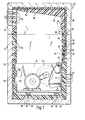
- FIG. 1 shows a device housing, generally designated 10, with a lower housing part 12 and an upper housing part 14.
- a device 16 is arranged, which in the present example has a blower 18. Otherwise, the structure of the device 16 is not essential for understanding the present invention.
- the device housing 10 comprises a rigid outer shell 20 made of plastic, metal or another suitable material, which is completely lined on the inside with an insulating layer 22 made of plastic foam.
- This insulation layer 22 thus covers the entire inner contour of the outer shell 20 with all corners, depressions, undercuts, so that no sound bridges can be formed at these points.
- An example of this is the stiffening ribs 24 formed on the outer shell 20 of the lower housing part 12. Only the projecting from the bottom of the lower housing part 12 mounting cams 26 on which the device 16 with the interposition of Schwingmetallmaschine 28 is fastened with the aid of screws 30 are only enclosed in the region of their jacket by the insulating layer 22, while the bearing surface for the Schwingmetallmaschine 28 remains uncovered.
- a mounting bracket 32 usually acts as a sound bridge, which is screwed with one leg to the device 16 and with its other leg to the outer shell 20 of the lower housing part. In order to reduce the sound transmission to a minimum here too, the mounting bracket 32 is embedded in the insulation layer 22 to such an extent that only part of the leg attached to the device 16 protrudes from the insulation layer 22.
- the insulation layer 22 In order to improve the sound-absorbing effect of the insulation layer 22, it can be provided on its inside with a profiled surface, as is shown in the area 34. It goes without saying that this profile can extend over the entire inner surface or over a desired part of the inner surface of the insulation layer 22.
- the area 34 is only intended to be an example of such a surface design.
- a rib 36 is formed on the abutting surface of the insulating layer of the lower housing part 12 facing the upper housing part 14, which rib engages in a complementary groove 38 which is formed in the corresponding abutting surface of the insulating layer 22 of the upper part 14.
- air inlet slots 40 are formed in the lower region of the lower housing part 12 and air outlet slots 42 in the upper region of the upper housing part 14.
- the sections 44 of the air inlet slots 40 running in the insulation layer 22 are cranked, i.e. designed angled in itself.
- the sound exit through the air inlet slots 40 is largely avoided.
- the air outlet slots 42, the section 46 of which extends in the insulating layer 22 are directed obliquely to the sections which extend in the outer shell 20.
- the insulation layer 22 is provided in the area of the top surface of the upper housing part 14 with an air guiding surface 48 which rises obliquely towards the air outlet slots 42.
- air guiding surfaces can be provided on the insulation layer 22 in any desired shape.
- cutouts 50 are formed in the insulating layer 22, the contours of which correspond to corresponding projections on the device 16.
- the inner layer of the insulating layer 22 can thus be completely adapted to the outer contour of the device to be accommodated.
- a layer 52 made of a specifically heavy material with material can be provided between the outer shell 20 and the insulation layer 22, as is shown on the left-hand side of FIG. 1 at the level of the device 16.
- an electrical shield in the form of a grid or perforated plate 54 can be embedded in the insulation layer 22, as is shown in the area of the upper housing part 14.
- An electrical shield in the form of a perforated plate also has a sound-absorbing function. Both the shield 54 and the heavy material layer 52 can of course extend over the entire inner circumference of the housing 10 or only over a certain part of the same. In Fig. 1 only one section was shown as an example.
- Cable management shafts can also be formed in the insulation layer 22.
- a channel-shaped profile 56 is embedded in the insulation layer 22, which is closed on its open side by the outer shell 20 and together with this forms a cable duct 58 for inserting cables 60.
- a mushroom-shaped groove 62 in cross-section or a dovetail-shaped groove 64 in cross-section is formed, into each of which a cable 65 or 66 can be pressed from the inside of the housing, which in the groove 62 or 64 is recorded.
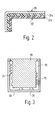
- the insulation layer 22 can also 3, the outer shell 20 is used as an outer mold, into which a correspondingly shaped inner mold 68 is inserted, whereupon the space 70 between the outer shell 20 and the inner mold 68 is foamed with an elastic plastic, which connects firmly to the outer shell 20.
- FIG. 3 shows this process schematically only for the production of the lower housing part 12.
- the sections 44 of the ventilation slots 40 are produced by shaped pieces 72 which, due to the elasticity of the plastic material, can be easily pulled out of the insulating layer after foaming.
- the objects to be embedded in the insulation layer must of course be arranged beforehand in the intermediate space 70. The techniques required for this are known per se and therefore do not need to be explained in more detail.
- Fig. 2 shows a partial section through a further embodiment of the invention, in which the insulating layer 22 is constructed from two partial layers 22a and 22b, which consist of plastic material of different densities. As a result, a larger range of sound frequencies can be effectively absorbed.
Abstract
Description
Die Erfindung betrifft ein schalldämmendes Gerätegehäuse mit einer starren Außenschale, an deren Innenseite schalldämmendes Material angeordnet ist.The invention relates to a soundproofing device housing with a rigid outer shell, on the inside of which soundproofing material is arranged.
Zur Schalldämmung von derartigen Gerätegehäuse ist es bisher bekannt, auf die Innenseite der Außenschale ein schalldämmendes Material aufzukleben. Diese Art der Auskleidung ist nicht nur arbeitsaufwendig und schwierig, sondern sie erfüllt hinsichtlich der Schalldämmung auch nicht die gestellten Anforderungen, da einerseits eine genaue Anpassung an die Gehäuseinnenform nicht immer möglich ist und andererseits die Eckbereiche des Gehäuses vielfach nicht mit schalldämmendem Material ausgekleidet werden können, so daß immer noch Schallbrücken vorhanden sind.For sound insulation of such a device housing, it is previously known to glue a sound-absorbing material to the inside of the outer shell. This type of lining is not only labor-intensive and difficult, but it also does not meet the requirements with regard to sound insulation, since on the one hand an exact adaptation to the interior shape of the housing is not always possible and on the other hand the corner areas of the housing can often not be lined with sound-absorbing material, so there are still sound bridges.
Der Erfindung liegt die Aufgabe zugrunde, ein schalldämmendes Gehäuse der eingangs genannten Art anzugeben, das einfach und preisgünstig herzustellen ist und erheblich verbesserte Schalldämmqualitäten besitzt. Diese Aufgabe wird erfindungsgemäß dadurch gelöst, daß die Außenschale auf ihrer Innenseite mit einer zusammenhängenden Dämmschicht aus einem elastischem Kunststoffschaum ausgekleidet ist. Eine derartige Dämmschicht kann erfindungsgemäß in einfacher Weise dadurch hergestellt werden, daß in die als Außenform dienende Außenschale eine Innenform eingesetzt wird und daß der Zwischenraum zwischen der Außenschale und der Innenform mit einem an der Außenschale haftenden elastischen Kunststoffschaum ausgeschäumt wird.The invention has for its object to provide a sound-absorbing housing of the type mentioned, which is simple and inexpensive to manufacture and has significantly improved sound insulation qualities. This object is achieved in that the outer shell is lined on its inside with a continuous insulation layer made of an elastic plastic foam. Such an insulating layer can be produced according to the invention in a simple manner by inserting an inner shape into the outer shell serving as the outer shape and by the space between the outer shell and the inner shape being adhered to the outer shell elastic plastic foam is foamed.
Durch die erfindungsgemäße Dämmschicht wird die Außenschale auf ihrer gesamten Innenseite abgedeckt, so daß keine Schallbrücken zurück bleiben. Unabhängig von der Innenkontur der Außenschale kann dabei die Dämmschicht mit einem geringen Arbeitsaufwand aufgebracht werden.The outer layer is covered on its entire inside by the insulating layer according to the invention, so that no sound bridges remain. Regardless of the inner contour of the outer shell, the insulation layer can be applied with little effort.
Um einen größeren Frequenzbereich abzuschirmen, kann die Dämmschicht aus einer Mehrzahl von Kunststoffschaumschichten unterschiedlicher Dichte bestehen, deren jede in einem bestimmten Frequenzbereich besonders gute Schalldämmeigenschaften besitzt. Zur Dämpfung des Körperschalles kann dabei zusätzlich eine Schicht aus einem Material hohen spezifischen Gewichtes in die Dämmschicht eingebettet oder an der Innenseite der Außenschale befestigt werden.In order to shield a larger frequency range, the insulation layer can consist of a plurality of plastic foam layers of different densities, each of which has particularly good sound insulation properties in a specific frequency range. To dampen the structure-borne noise, a layer of a material with a high specific weight can also be embedded in the insulation layer or attached to the inside of the outer shell.
Ohne Erhöhung des Arbeitsaufwandes kann die Dämmschicht auf ihrer Innenseite mit einem schallschluckenden Profil versehen werden. Durch eine geeignete Wahl der Profilquerschnitte bzw. Profilzwischenräume entsprechend den auftretenden Schallwellenlängen kann dabei eine gesteigerte Absorption des Schalles in bestimmten Frequenzbereichen erreicht werden. Ein solches Profil kann Rippen, Vertiefungen oder Kegelstrukturen oder beispielsweise eine Kombination derartiger Formen aufweisen.Without increasing the amount of work, the insulation layer can be provided with a sound-absorbing profile on the inside. Through a suitable choice of the profile cross-sections or profile interspaces in accordance with the occurring sound wavelengths, an increased absorption of the sound in certain frequency ranges can be achieved. Such a profile can have ribs, depressions or cone structures or, for example, a combination of such shapes.
Über die bereits genannten Vorteile hinaus hat die erfindungsgemäße Dämmschicht auch eine klimatisierende Wirkung, da sie den Wärmeaustausch zwischen dem Gehäuseinnenraum und dem Gehäuseaußenraum erschwert.In addition to the advantages already mentioned, the insulation layer according to the invention also has an air-conditioning effect, since it exchanges heat between the housing interior and the exterior of the housing difficult.
Mit dem erfindungsgemäßen Verfahren ist es ohne Mühe möglich, die Dämmschicht so auszubilden, daß sie eine der Kontur des aufzunehmenden Gerätes oder eines Teiles desselben angepaßte Innenoberfläche aufweist. Dadurch läßt sich der vorhandene Zwischenraum zwischen dem Gerät und dem Gerätegehäuse optimal für die Geräuschdämpfung nutzen.With the method according to the invention, it is easily possible to design the insulating layer so that it has an inner surface adapted to the contour of the device to be accommodated or a part thereof. This allows the existing space between the device and the device housing to be used optimally for noise reduction.
Bei einem mehrteiligen Gerätegehäuse ist es zur Abdichtung zwischen den einzelnen Gehäuseteilen zweckmäßig, wenn in jeweils einer von zwei zur Anlage aneinander bestimmten Stoßflächen der Dämmschicht eine Nut und in der jeweils anderen Stoßfläche eine in die Nut eingreifende Feder ausgebildet ist.In the case of a multi-part device housing, it is expedient for sealing between the individual housing parts if a groove is formed in one of two abutting surfaces of the insulating layer intended for abutment against one another and a spring engaging in the groove is formed in the other abutting surface.
Falls es erforderlich ist, kann in die Dämmschicht eine elektrische Abschirmung wie beispielsweise ein Gitter oder Lochblech eingebettet sein. Letzteres kann auch gleichzeitig als Schalldämmelement verwendet werden.If necessary, an electrical shield such as a grid or perforated plate can be embedded in the insulation layer. The latter can also be used as a sound insulation element at the same time.
Das Ausschäumen der Außenschale mit der Dämmschicht bietet die Möglichkeit, in der Dämmschicht Kabelführungen auszubilden. Die Kabelführungenkönnen dabei mit Hilfe von in die Dämmschicht eingebetteten Profilen gebildet werden; es besteht jedoch auch die Möglichkeit, die Kabelführungen in Form von Führungsnuten auszubilden, die zur Gehäuseinnenseite hin offen sind und welche die Kabel eingedrückt werden.Foaming the outer shell with the insulation layer offers the possibility of forming cable ducts in the insulation layer. The cable guides can be formed with the help of profiles embedded in the insulation layer; however, there is also the possibility of designing the cable guides in the form of guide grooves which are open towards the inside of the housing and which the cables are pressed in.
Üblicherweise sind in einem solchen Gerätegehäuse Ein-und Austrittsöffnungen wie Lüftungsschlitze oder dergleichen ausgebildet. Das erfindungsgemäße Verfahren zur Herstellung der Dämmschicht bietet die Möglichkeit, auf einfache Weise einen gewissen Schleuseneffekt an den Ein- undAustrittsöffnungen zu erreichen, in dem die in der Dämmschicht verlaufenden Abschnitte der Ein- und Austrittsöffnungenmindestens auf einem Teil ihrer Länge gegenüber dem in der Außenschale verlaufenden Abschnitt schräg verlaufen. Beispielsweise können die in der Dämmschicht verlaufenden Abschnitte abgekröpft oder geknickt verlaufen, so daß das innere und das äußere Ende der Ein- und Austrittsöffnungen nicht durch eine gerade Linie miteinander verbunden werden können.In such a device housing, there are usually and outlet openings such as ventilation slots or the like are formed. The method according to the invention for producing the insulation layer offers the possibility of easily achieving a certain lock effect at the inlet and outlet openings, in that the sections of the inlet and outlet openings running in the insulation layer are at least part of their length compared to the section running in the outer shell run obliquely. For example, the sections running in the insulation layer can be bent or bent so that the inner and outer ends of the inlet and outlet openings cannot be connected to one another by a straight line.
Bei einer Belüftung des in dem Gehäuse eingeschlossenen Gerätes können mit dem erfindungsgemäßen Verfahren sehr einfach an der Innenseite der Dämmschicht Luftleitflächen ausgebildet werden, welche den Lüftungsstrom in eine gewünschte Richtung lenken.When the device enclosed in the housing is ventilated, the method according to the invention can be used to very easily form air guiding surfaces on the inside of the insulating layer, which guide the ventilation flow in a desired direction.
Üblicherweise bilden die Verbindungselemente zwischen dem geräuscherzeugenden Gerät und dem Gehäuse Schallbrücken. Die Schallübertragung über die Schallbrücken kann auf ein Minimum dadurch beschränkt werden, daß die Verbindungselemente in die Dämmschicht soweit eingebettet sind, daß nur die mit dem Gerät oder den Geräteteilen unmittelbar in Berührung tretenden Abschnitte aus der Dämmschicht herausragen.The connecting elements between the noise-generating device and the housing usually form sound bridges. The sound transmission via the sound bridges can be reduced to a minimum by the fact that the connecting elements are embedded in the insulation layer to such an extent that only the sections that come into direct contact with the device or the device parts protrude from the insulation layer.
Weitere Merkmale und Vorteile der Erfindung ergeben sich aus der folgenden Beschreibung, welche in Verbindung mit den beigefügten Zeichnungen die Erfindung anhand von Ausführungsbeispielen erläutert. Es zeigen:
- Fig. 1 einen schematischen Schnitt durch ein Gerätegehäuse mit einem darin untergebrachten Gerät,
- Fig. 2 einen Teilschnitt durch eine zweite Ausführungsform der Erfindung, und
- Fig. 3 eine schematische Skizze zur Erläuterung der Herstellung der Dämmschicht.
- 1 shows a schematic section through a device housing with a device accommodated therein,
- Fig. 2 is a partial section through a second embodiment of the invention, and
- Fig. 3 is a schematic sketch to explain the manufacture of the insulation layer.
In der Fig. 1 erkennt man ein allgemein mit 10 bezeichnetes Gerätegehäuse mit einem Gehäuseunterteil 12 und einem Gehäuseoberteil 14. In dem Gehäuseunterteil 12 ist ein Gerät 16 angeordnet, das im vorliegeden Beispiel ein Gebläse 18 aufweist. Im übrigen ist der Aufbau des Gerätes 16 für das Verständnis der vorliegenden Erfindung nicht wesentlich.1 shows a device housing, generally designated 10, with a
Das Gerätegehäuse 10 umfaßt eine steife Außenschale 20 aus Kunststoff, Metall oder einem anderen geeigneten Material, die auf ihrer Innenseite mit einer aus Kunststoffschaum bestehenden Dämmschicht 22 vollständig ausgekleidet ist. Diese Dämmschicht 22 überdeckt somit die gesamte Innenkontur der Außenschale 20 mit allen Ecken, Vertiefungen, Hinterschneidungen, so daß an diesen Stellen keine Schallbrücken gebildet werden können. Als Beispiel seien hierfür die an der Außenschale 20 des Gehäuseunterteils 12 ausgebildeten Versteifungsrippen 24 genannt. Nur die vom Boden des Gehäuseunterteiles 12 vorstehenden Befestigungsnocken 26, auf denen das Gerät 16 unter der Zwischenschaltung von Schwingmetallteilen 28 mit Hilfe von Schrauben 30 befestigt ist, sind nur im Bereich ihres Mantels von der Dämmschicht 22 umschlossen, während die Auflagefläche für die Schwingmetallteile 28 unbedeckt bleibt.The
Als Schallbrücke wirkt überlicherweise auch ein Befestigungswinkel 32, der mit seinem einen Schenkel an dem Gerät 16 und mit seinem anderen Schenkel an der Außenschale 20 des Gehäuseunterteiles angeschraubt ist. Um auch hier die Schallübertragung auf ein Minimum zu reduzieren, ist der Befestigungswinkel 32 soweit in die Dämmschicht 22 eingebettet, daß nur ein Teil des am Gerät 16 befestigten Schenkels aus der Dämmschicht 22 herausragt.A
Um die schallabsorbierende Wirkung der Dämmschicht 22 zu verbessern, kann diese auf ihrer Innenseite mit einer profilierten Oberfläche versehen sein, wie dies in dem Bereich 34 dargestellt ist. Es versteht sich, daß dieses Profil sich über die gesamte Innenoberfläche oder über einen gewünschten Teil der Innenoberfläche der Dämmschicht 22 erstrecken kann. Der Bereich 34 soll lediglich als Beispiel für eine derartigen Oberflächengestaltung gelten.In order to improve the sound-absorbing effect of the
Zur Abdichtung zwischen dem Gehäuseoberteil 14 und dem Gehäuseunterteil 12 ist an der dem Gehäuseoberteil 14 zugewandten Stoßfläche der Dämmschicht des Gehäuseunterteiles 12 eine Rippe 36 ausgebildet, die in eine komplementäre Nut 38 eingreift, die in der entsprechenden Stoßfläche der Dämmschicht 22 des Oberteiles 14 ausgeformt ist.For sealing between the
Für die Belüftung des Gehäuseinnenraumes mittels des Gebläses 18 sind Lufteintrittsschlitze 40 im unteren Bereich des Gehäuseunterteils 12 und Luftaustrittsschlitze 42 im oberen Bereich des Gehäuseoberteiles 14 ausgebildet. Wie man erkennt, sind die in der Dämmschicht 22 verlaufenden Abschnitte 44 der Lufteintrittsschlitze 40 gekröpft, d.h. in sich abgewinkelt gestaltet. Dadurch wird der Schallaustritt durch die Lufteintrittsschlitze 40 weitgehend vermieden. Das gleiche gilt für die Luftaustrittsschlitze 42, deren in der Dämmschicht 22 verlaufender Abschnitt 46 schräg zu den in der Außenschale 20 verlaufenden Abschnitten gerichtet sind.For the ventilation of the interior of the housing by means of the
Um die von dem Gebläse 18 angesaugte Luft zu den Luftaustrittsschlitzen 42 zu leiten, ist die Dämmschicht 22 im Bereich der Deckfläche des Gehäuseoberteiles 14 mit einer schräg zu den Luftaustrittsschlitzen 42 hin ansteigenden Luftleitfläche 48 versehen. Solche Luftleitflächen können in jeder gewünschten Form an der Dämmschicht 22 vorgesehen sein.In order to guide the air sucked in by the
Im Bereich des Gerätes 16 sind in der Dämmschicht 22 Aussparungen 50 ausgebildet, die in ihrer Kontur mit entsprechenden Vorsprüngen an dem Gerät 16 übereinstimmen. Dadurch wird der Zwischenraum zwischen der Außenschale 20 und dem Gerät 16 optimal für die Geräuschdämpfung genutzt. Die Dämmschicht 22 kann in ihrer Innenkontur somit vollständig an die Außenkontur des aufzunehmenden Gerätes angepaßt sein.In the area of the
In die Dämmschicht 22 lassen sich verschiedene Elemente einbetten, die für die Schallabsoption oder für die spätere Nutzung des Gerätes wesentlich sind. So kann zur besseren Körperschalldämpfung beispielsweise eine Schicht 52 aus einem spezifisch schweren mit Material zwischen der Außenschale 20 und der Dämmschicht 22 vorgesehen sein, wie dies auf der linken Seite der Fig. 1 in Höhe des Gerätes 16 dargestellt ist. Ferner kann eine elektrische Abschirmung in Form eines Gitters oder Lochbleches 54 in die Dämmschicht 22 eingebettet sein, wie dies im Bereich des Gehäuseoberteiles 14 dargestellt ist. Eine elektrische Abschirmung in Form eines Lochbleches hat gleichzeitig eine Schallabsorbierende Funktion. Sowohl die Abschirmung 54 als auch die Schwermaterialschicht 52 können sich selbstverständlich über den gesamten Innenumfang des Gehäuses 10 oder nur über einen bestimmten Teil desselben erstrecken. In der Fig. 1 wurde lediglich jeweils ein Abschnitt als Beispiel dargestellt.Various elements can be embedded in the
In der Dämmschicht 22 können auch Kabelführungsschächte ausgebildet sein. Eine Möglichkeit zu Ihrer Bildung besteht darin, daß in die Dämmschicht 22 ein rinnenförmiges Profil 56 eingebettet ist, das an seiner offenen Seite von der Außenschale 20 abgeschlossen wird und zusammen mit dieser einen Kabelschacht 58 zum Einschieben von Kabeln 60 bildet. Eine andere Möglichkeit besteht darin, daß in der Dämmschicht 22 eine im Querschnitt pilzförmige Nut 62 oder eine im Querschnitt schwalbenschwanzförmige Nut 64 ausgebildet ist, in die jeweils von der Gehäuseinnenseite her ein Kabel 65 bzw. 66 eingedrückt werden kann, das in der Nut 62 bzw. 64 festgehalten wird.Cable management shafts can also be formed in the
Trotz ihrer komplexen Form kann die Dämmschicht 22 auch auf einfache Weise und kostengünstig hergestellt werden, in dem gemäß Fig. 3 die Außenschale 20 als eine Außenform verwendet wird, in die eine entsprechend gestalte Innenform 68 eingesetzt wird, worauf der Zwischenraum 70 zwischen Außenschale 20 und Innenform 68 mit einem elastischen Kunststoff ausgeschäumt wird, der sich fest mit der Außenschale 20 verbindet. Die Fig. 3 zeigt diesen Vorgang schematisch nur für die Herstellung des Gehäuseunterteiles 12. Die Abschnitte 44 der Lüftungsschlitze 40 werden dabei durch Formstücke 72 erzeugt, die aufgrund der Elastizität des Kunststoffmaterials nach dem Schäumen ohne Mühe aus der Dämmschicht herausgezogen werden können. Die in die Dämmschicht einzubettenden Gegenstände müssen selbstverständlich vorher in dem Zwischenraum 70 angeordnet werden. Die hierzu erforderlichen Techniken sind an sich bekannt und brauchen daher nicht näher erläutert zu werden.Despite its complex shape, the
Fig. 2 zeigt noch einenTeilschnitt durch eine weitere Ausführungsform der Erfindung, bei welcher die Dämmschicht 22 aus zwei Teilschichten 22a und 22b aufgebaut ist, die aus Kunststoffmaterial unterschiedlicher Dichte bestehen. Dadurch kann ein größerer Bereich von Schallfrequenzen wirkungsvoll absorbiert werden.Fig. 2 shows a partial section through a further embodiment of the invention, in which the insulating
Die vorstehende Beschreibung zeigt, daß mit der erfindungsgemäßen Lösung auf einfachste Weise eine vollständige Abdeckung der Gehäuseinnenwand erreicht wird, so daß alle Schallbrücken vom Gehäuseinnenraum zum Gehäuseaußenraum weitgehend vermieden werden. Somit wird eine optimale Schalldämmung erreicht, wobei es die Herstellung der Dämmschicht aus einem Kunststoffschaum ermöglicht, in der Dämmschicht eine Vielzahl von Einbauteilen einzubetten und Einformungen vorzusehen, die für die spätere Nutzung des Gehäuses wesentlich sind, so daß beim Einbau eines Gerätes in das Gehäuse ein wesentlicher Teil der früher erforderlichen Arbeiten entfällt. Ein weiterer Vorteil der erfindungsgemäßen Lösung ist noch darin zu sehen, daß durch die vollständige Überdeckung der Innenoberfläche der Außenschale keine zu lackierenden Flächen übrig bleiben, die früher unter Aufwand von Material und Arbeitszeit lackiert werden mußten.The above description shows that with the solution according to the invention a complete covering of the housing inner wall is achieved in the simplest way, so that all sound bridges from the housing interior to the housing exterior are largely avoided. This ensures optimal sound insulation, whereby the production of the insulating layer from a plastic foam enables a plurality of built-in parts to be embedded in the insulating layer and to provide indentations which are essential for the later use of the housing, so that when a device is installed in the housing a substantial part of the work previously required is eliminated . Another advantage of the solution according to the invention can be seen in the fact that the complete covering of the inner surface of the outer shell means that there are no areas left to be painted, which previously had to be painted with the expenditure of material and working time.
Claims (15)
Applications Claiming Priority (2)
| Application Number | Priority Date | Filing Date | Title |
|---|---|---|---|
| DE3112591 | 1981-03-30 | ||
| DE19813112591 DE3112591C2 (en) | 1981-03-30 | 1981-03-30 | Sound-insulating, closed device housing |
Publications (2)
| Publication Number | Publication Date |
|---|---|
| EP0062166A2 true EP0062166A2 (en) | 1982-10-13 |
| EP0062166A3 EP0062166A3 (en) | 1984-02-22 |
Family
ID=6128735
Family Applications (1)
| Application Number | Title | Priority Date | Filing Date |
|---|---|---|---|
| EP82101700A Withdrawn EP0062166A3 (en) | 1981-03-30 | 1982-03-04 | Sound-proofed apparatus housing, and method for its manufacture |
Country Status (3)
| Country | Link |
|---|---|
| EP (1) | EP0062166A3 (en) |
| JP (1) | JPS57169797A (en) |
| DE (1) | DE3112591C2 (en) |
Cited By (10)
| Publication number | Priority date | Publication date | Assignee | Title |
|---|---|---|---|---|
| EP0304398A1 (en) * | 1987-08-21 | 1989-02-22 | Leica Aarau AG | Instrument having a housing |
| WO1999022794A1 (en) * | 1997-11-03 | 1999-05-14 | Resmed Limited | Noise damping mounting body for cpap compressor |
| US6532957B2 (en) | 1996-09-23 | 2003-03-18 | Resmed Limited | Assisted ventilation to match patient respiratory need |
| US6776155B2 (en) | 1997-05-16 | 2004-08-17 | Resmed Limited | Nasal ventilation as a treatment for stroke |
| WO2005001215A1 (en) | 2003-06-25 | 2005-01-06 | Parker, Ronald, Brian | Sound attenuating apparatus for machinery |
| US6951263B2 (en) | 2000-04-12 | 2005-10-04 | Carcoustics Tech Center Gmbh | Sound absorber, especially for motor vehicles, and a method for producing a sound absorber |
| EP1772480A1 (en) * | 2005-10-06 | 2007-04-11 | Henkel KGaA | Reduction of transfer of vibrations |
| US7931023B2 (en) | 1991-12-20 | 2011-04-26 | Resmed Limited | Patient interface assembly for CPAP respiratory apparatus |
| CN106025847A (en) * | 2016-06-08 | 2016-10-12 | 佘峰 | Noise-reduction electrical equipment protection box with high stability |
| DE102019117717A1 (en) * | 2019-07-01 | 2021-01-07 | Wolf Gmbh | Cladding part and sound insulation hood for a heat pump |
Families Citing this family (6)
| Publication number | Priority date | Publication date | Assignee | Title |
|---|---|---|---|---|
| CA2232546A1 (en) | 1995-09-18 | 1997-03-27 | Resmed Limited | Pressure control in cpap treatment or assisted respiration |
| AUPO742297A0 (en) | 1997-06-18 | 1997-07-10 | Resmed Limited | An apparatus for supplying breathable gas |
| DE19839968C2 (en) * | 1998-09-02 | 2000-06-21 | Siemens Nixdorf Inf Syst | Arrangement and method for sound insulation |
| DE19925661A1 (en) * | 1999-06-04 | 2000-12-07 | Volkswagen Ag | Acoustic compact insulation |
| DE10007419A1 (en) * | 2000-02-18 | 2001-08-30 | Fujitsu Siemens Computers Gmbh | Device for reducing the noise level and for cooling a component with moving parts |
| DE102006058840B4 (en) * | 2006-12-13 | 2021-01-14 | Pfeiffer Vacuum Gmbh | Vacuum pump |
Citations (3)
| Publication number | Priority date | Publication date | Assignee | Title |
|---|---|---|---|---|
| US3855028A (en) * | 1972-11-08 | 1974-12-17 | D Larson | Method of fabricating structures |
| FR2388360A1 (en) * | 1977-04-20 | 1978-11-17 | Turati Giuseppe | Sound-proof casing for equipment - has sides fitting into slots in frames at top and bottom to prevent sound leakage |
| GB2056360A (en) * | 1979-07-31 | 1981-03-18 | Teroson Gmbh | A process for producing a sound-insulating and sound- absorbing shaped part and a shaped part having a foam layer |
Family Cites Families (5)
| Publication number | Priority date | Publication date | Assignee | Title |
|---|---|---|---|---|
| DE1037572B (en) * | 1955-10-21 | 1958-08-28 | Licentia Gmbh | Electric machine in which the sheet metal stacks are united with the parts that carry them with an adhesive |
| US2989855A (en) * | 1960-03-07 | 1961-06-27 | Gen Motors Corp | Refrigerating apparatus |
| DE2045718A1 (en) * | 1970-09-16 | 1972-03-23 | Baus H | |
| FR2350556A1 (en) * | 1976-05-04 | 1977-12-02 | Segic | Sound attenuating ventilation unit for habitable rooms - has labyrinth air passage between attenuating sides of varying thickness |
| DE2923077B1 (en) * | 1979-06-07 | 1980-08-21 | Klein Schanzlin & Becker Ag | Noise protection hood for electric motors |
-
1981
- 1981-03-30 DE DE19813112591 patent/DE3112591C2/en not_active Expired
-
1982
- 1982-03-04 EP EP82101700A patent/EP0062166A3/en not_active Withdrawn
- 1982-03-26 JP JP57047500A patent/JPS57169797A/en active Pending
Patent Citations (3)
| Publication number | Priority date | Publication date | Assignee | Title |
|---|---|---|---|---|
| US3855028A (en) * | 1972-11-08 | 1974-12-17 | D Larson | Method of fabricating structures |
| FR2388360A1 (en) * | 1977-04-20 | 1978-11-17 | Turati Giuseppe | Sound-proof casing for equipment - has sides fitting into slots in frames at top and bottom to prevent sound leakage |
| GB2056360A (en) * | 1979-07-31 | 1981-03-18 | Teroson Gmbh | A process for producing a sound-insulating and sound- absorbing shaped part and a shaped part having a foam layer |
Non-Patent Citations (2)
| Title |
|---|
| IBM TECHNICAL DISCLOSURE BULLETIN, Band 18, Nr. 12, Mai 1976, Seite 4172, New York, USA * |
| IBM TECHNICAL DISCLOSURE BULLETIN, Band 20, Nr. 12, Mai 1978, Seiten 207-208, New York, USA * |
Cited By (20)
| Publication number | Priority date | Publication date | Assignee | Title |
|---|---|---|---|---|
| EP0304398A1 (en) * | 1987-08-21 | 1989-02-22 | Leica Aarau AG | Instrument having a housing |
| US7931023B2 (en) | 1991-12-20 | 2011-04-26 | Resmed Limited | Patient interface assembly for CPAP respiratory apparatus |
| US8733351B2 (en) | 1996-09-23 | 2014-05-27 | Resmed Limited | Method and apparatus for providing ventilatory assistance |
| US7644713B2 (en) | 1996-09-23 | 2010-01-12 | Resmed Limited | Method and apparatus for determining instantaneous leak during ventilatory assistance |
| US6810876B2 (en) | 1996-09-23 | 2004-11-02 | Resmed Ltd. | Assisted ventilation to match patient respiratory need |
| US9974911B2 (en) | 1996-09-23 | 2018-05-22 | Resmed Limited | Method and apparatus for providing ventilatory assistance |
| US6688307B2 (en) | 1996-09-23 | 2004-02-10 | Resmed Limited | Methods and apparatus for determining instantaneous elastic recoil and assistance pressure during ventilatory support |
| US8051853B2 (en) | 1996-09-23 | 2011-11-08 | Resmed Limited | Method and apparatus for providing ventilatory assistance |
| US6532957B2 (en) | 1996-09-23 | 2003-03-18 | Resmed Limited | Assisted ventilation to match patient respiratory need |
| US6776155B2 (en) | 1997-05-16 | 2004-08-17 | Resmed Limited | Nasal ventilation as a treatment for stroke |
| WO1999022794A1 (en) * | 1997-11-03 | 1999-05-14 | Resmed Limited | Noise damping mounting body for cpap compressor |
| US6951263B2 (en) | 2000-04-12 | 2005-10-04 | Carcoustics Tech Center Gmbh | Sound absorber, especially for motor vehicles, and a method for producing a sound absorber |
| WO2005001215A1 (en) | 2003-06-25 | 2005-01-06 | Parker, Ronald, Brian | Sound attenuating apparatus for machinery |
| US7364221B2 (en) | 2005-10-06 | 2008-04-29 | Henkel Kommanditgesellschaft Auf Aktien | Reduction of vibration transfer |
| WO2007039308A1 (en) * | 2005-10-06 | 2007-04-12 | Henkel Kgaa | Reduction of vibration transfer |
| EP1772480A1 (en) * | 2005-10-06 | 2007-04-11 | Henkel KGaA | Reduction of transfer of vibrations |
| CN101341199B (en) * | 2005-10-06 | 2012-03-28 | 汉高两合股份公司 | Reduction of transfer of vibrations |
| CN106025847A (en) * | 2016-06-08 | 2016-10-12 | 佘峰 | Noise-reduction electrical equipment protection box with high stability |
| CN106025847B (en) * | 2016-06-08 | 2017-12-22 | 江苏盐阜电站阀门辅机制造有限公司 | A kind of high noise reduction power equipment protective housing of stability |
| DE102019117717A1 (en) * | 2019-07-01 | 2021-01-07 | Wolf Gmbh | Cladding part and sound insulation hood for a heat pump |
Also Published As
| Publication number | Publication date |
|---|---|
| DE3112591C2 (en) | 1983-12-29 |
| JPS57169797A (en) | 1982-10-19 |
| DE3112591A1 (en) | 1982-10-14 |
| EP0062166A3 (en) | 1984-02-22 |
Similar Documents
| Publication | Publication Date | Title |
|---|---|---|
| EP0062166A2 (en) | Sound-proofed apparatus housing, and method for its manufacture | |
| DE1680066B2 (en) | Sunroof construction for automobiles | |
| DE2902831A1 (en) | SOUND AND THERMAL INSULATION WALL | |
| CH672932A5 (en) | Noise-attenuating wall section - contains insulating layers of different densities, with first layer held clear of front wall by distance piece | |
| DE3441769A1 (en) | VENTILATION DEVICE FOR ROOMS | |
| DE202005012384U1 (en) | Rolling shutter unit for installation into window or door openings in building walls comprises an inspection opening which is located in the bottom of the shutter box, and is accessible from outside | |
| EP0947638B1 (en) | Insulation panel for use on exterior facades of houses | |
| DE2943953C2 (en) | Heald bar | |
| WO2014111219A1 (en) | Structural profile element | |
| EP0940518A1 (en) | Cladding element for covering building walls | |
| EP1233137A2 (en) | Device for sealing the lower edge of a door without a threshold | |
| DE2716957A1 (en) | INSULATION, IN PARTICULAR FOAM MOLDED BODY | |
| DE10359157A1 (en) | Heat-conductive insert mat for electrical and electronic devices and method for producing such insert mats | |
| DE19959123B4 (en) | Sound- and / or heat-insulating mat | |
| EP0835979B1 (en) | Roller shutter and internal cover therefor | |
| EP0149053A2 (en) | Ventilation apparatus for rooms | |
| DE3530431C2 (en) | ||
| DE3343773C2 (en) | ||
| EP0670450B1 (en) | Fastening clamp | |
| DE2616787A1 (en) | Double skinned cladding panel - consists of two flanged trays clamped together by dumb bell shaped interior member | |
| DE20319931U1 (en) | Compound profile for use in air-conditioning units and installations, noise attenuation hoods and the like comprises at least two electrically conductive carrier elements with multiply bent end sections | |
| DE2819657A1 (en) | Machine or engine air duct sound insulation - has walling made solely of foamed plastic, pref. polyether or polyurethane | |
| EP1300527A2 (en) | Device for fixing listel rails, especially listel rails designed as skirting boards | |
| DE3240474A1 (en) | Fire protection device for an encased cable duct passing through building walls, ceilings and the like | |
| DE19519416C1 (en) | Pipe joint or union used in heating system |
Legal Events
| Date | Code | Title | Description |
|---|---|---|---|
| PUAI | Public reference made under article 153(3) epc to a published international application that has entered the european phase |
Free format text: ORIGINAL CODE: 0009012 |
|
| AK | Designated contracting states |
Designated state(s): AT BE CH DE FR GB IT LI NL SE |
|
| PUAL | Search report despatched |
Free format text: ORIGINAL CODE: 0009013 |
|
| RHK1 | Main classification (correction) |
Ipc: G10K 11/16 |
|
| AK | Designated contracting states |
Designated state(s): AT BE CH DE FR GB IT LI NL SE |
|
| STAA | Information on the status of an ep patent application or granted ep patent |
Free format text: STATUS: THE APPLICATION IS DEEMED TO BE WITHDRAWN |
|
| 18D | Application deemed to be withdrawn |
Effective date: 19841023 |
|
| RIN1 | Information on inventor provided before grant (corrected) |
Inventor name: SCHMEYKAL, RUDOLF Inventor name: DOEINGHAUS, HERMANN |