EP0063745A2 - Regulating device for a self piloted inverter with an intermediate D.C. circuit - Google Patents
Regulating device for a self piloted inverter with an intermediate D.C. circuit Download PDFInfo
- Publication number
- EP0063745A2 EP0063745A2 EP82103133A EP82103133A EP0063745A2 EP 0063745 A2 EP0063745 A2 EP 0063745A2 EP 82103133 A EP82103133 A EP 82103133A EP 82103133 A EP82103133 A EP 82103133A EP 0063745 A2 EP0063745 A2 EP 0063745A2
- Authority
- EP
- European Patent Office
- Prior art keywords
- voltage
- inverter
- input
- control
- value
- Prior art date
- Legal status (The legal status is an assumption and is not a legal conclusion. Google has not performed a legal analysis and makes no representation as to the accuracy of the status listed.)
- Granted
Links
Images

Classifications
-
- H—ELECTRICITY
- H02—GENERATION; CONVERSION OR DISTRIBUTION OF ELECTRIC POWER
- H02M—APPARATUS FOR CONVERSION BETWEEN AC AND AC, BETWEEN AC AND DC, OR BETWEEN DC AND DC, AND FOR USE WITH MAINS OR SIMILAR POWER SUPPLY SYSTEMS; CONVERSION OF DC OR AC INPUT POWER INTO SURGE OUTPUT POWER; CONTROL OR REGULATION THEREOF
- H02M5/00—Conversion of ac power input into ac power output, e.g. for change of voltage, for change of frequency, for change of number of phases
- H02M5/40—Conversion of ac power input into ac power output, e.g. for change of voltage, for change of frequency, for change of number of phases with intermediate conversion into dc
- H02M5/42—Conversion of ac power input into ac power output, e.g. for change of voltage, for change of frequency, for change of number of phases with intermediate conversion into dc by static converters
- H02M5/44—Conversion of ac power input into ac power output, e.g. for change of voltage, for change of frequency, for change of number of phases with intermediate conversion into dc by static converters using discharge tubes or semiconductor devices to convert the intermediate dc into ac
- H02M5/443—Conversion of ac power input into ac power output, e.g. for change of voltage, for change of frequency, for change of number of phases with intermediate conversion into dc by static converters using discharge tubes or semiconductor devices to convert the intermediate dc into ac using devices of a thyratron or thyristor type requiring extinguishing means
- H02M5/45—Conversion of ac power input into ac power output, e.g. for change of voltage, for change of frequency, for change of number of phases with intermediate conversion into dc by static converters using discharge tubes or semiconductor devices to convert the intermediate dc into ac using devices of a thyratron or thyristor type requiring extinguishing means using semiconductor devices only
- H02M5/4505—Conversion of ac power input into ac power output, e.g. for change of voltage, for change of frequency, for change of number of phases with intermediate conversion into dc by static converters using discharge tubes or semiconductor devices to convert the intermediate dc into ac using devices of a thyratron or thyristor type requiring extinguishing means using semiconductor devices only having a rectifier with controlled elements
-
- H—ELECTRICITY
- H02—GENERATION; CONVERSION OR DISTRIBUTION OF ELECTRIC POWER
- H02M—APPARATUS FOR CONVERSION BETWEEN AC AND AC, BETWEEN AC AND DC, OR BETWEEN DC AND DC, AND FOR USE WITH MAINS OR SIMILAR POWER SUPPLY SYSTEMS; CONVERSION OF DC OR AC INPUT POWER INTO SURGE OUTPUT POWER; CONTROL OR REGULATION THEREOF
- H02M7/00—Conversion of ac power input into dc power output; Conversion of dc power input into ac power output
- H02M7/42—Conversion of dc power input into ac power output without possibility of reversal
- H02M7/44—Conversion of dc power input into ac power output without possibility of reversal by static converters
- H02M7/48—Conversion of dc power input into ac power output without possibility of reversal by static converters using discharge tubes with control electrode or semiconductor devices with control electrode
- H02M7/505—Conversion of dc power input into ac power output without possibility of reversal by static converters using discharge tubes with control electrode or semiconductor devices with control electrode using devices of a thyratron or thyristor type requiring extinguishing means
- H02M7/515—Conversion of dc power input into ac power output without possibility of reversal by static converters using discharge tubes with control electrode or semiconductor devices with control electrode using devices of a thyratron or thyristor type requiring extinguishing means using semiconductor devices only
- H02M7/525—Conversion of dc power input into ac power output without possibility of reversal by static converters using discharge tubes with control electrode or semiconductor devices with control electrode using devices of a thyratron or thyristor type requiring extinguishing means using semiconductor devices only with automatic control of output waveform or frequency
- H02M7/527—Conversion of dc power input into ac power output without possibility of reversal by static converters using discharge tubes with control electrode or semiconductor devices with control electrode using devices of a thyratron or thyristor type requiring extinguishing means using semiconductor devices only with automatic control of output waveform or frequency by pulse width modulation
-
- F—MECHANICAL ENGINEERING; LIGHTING; HEATING; WEAPONS; BLASTING
- F02—COMBUSTION ENGINES; HOT-GAS OR COMBUSTION-PRODUCT ENGINE PLANTS
- F02B—INTERNAL-COMBUSTION PISTON ENGINES; COMBUSTION ENGINES IN GENERAL
- F02B3/00—Engines characterised by air compression and subsequent fuel addition
- F02B3/06—Engines characterised by air compression and subsequent fuel addition with compression ignition
Abstract
Description
Die Erfindung bezieht sich auf eine Regelanordnung für einen selbstgeführten, nach dem Pulsbreitenmodulationsverfahren betriebenen Wechselrichter mit Gleichspannungszwischenkreis, wobei die Steuerbefehle für die Stromrichterventile des Wechselrichters durch Schnittpunktbildung einer Steuerspannung mit einer Hilfsspannung gewonnen werden.The invention relates to a control arrangement for a self-commutated inverter operated according to the pulse-width modulation method with a DC voltage intermediate circuit, the control commands for the converter valves of the inverter being obtained by forming a control voltage with an auxiliary voltage.
Ein Pulsbreitenmodulationsverfahren (Unterschwingungsverfahren) ist beispielsweise aus dem BBC-Silizium-Stromrichter-Handbuch, 1971, Seite 213 bis 216 bekannt. Es eignet sich zur Pulsbreitenmodulation für einen selbstgeführten Wechselrichter mit Gleichspannungszwischenkreis, wie in den Figuren 1 bis 4 dargestellt. In der Figur 1 ist ein zweiphasiger Zwischenkreis-Wechselrichter mit Gleichspannungszwischenkreis dargestellt. Zwischen den Eingangsklemmen 1 und 2 des Zwischenkreises liegt die Eingangsgleichspannung UE an. Mit den Klemmen 1 und 2 ist ein Stützkondensator 3 verbunden. An Klemme 1 sind zünd- und löschbare Stromrichterventile 4 und 5 sowie an Klemme 2 zünd-und löschbare Stromrichterventile 6 und 7 angeschlossen. Die Ventile 4 und 6 sowie 5 und 7 sind jeweils miteinander verbunden. Am gemeinsamen Verbindungspunkt der Ventile 4 und 6 liegt die erste Klemme eines induktiven Verbrauchers 8, dessen zweite Klemme an den gemeinsamen Verbindungspunkt der Ventile 5 und 7 angeschlossen ist. Zwischen den Klemmen des Verbrauchers 8 liegt die Ausgangsspannung UA an.A pulse width modulation method (undershoot method) is known, for example, from the BBC silicon power converter manual, 1971, pages 213 to 216. It is suitable for pulse width modulation for a self-commutated inverter with a DC link, as shown in FIGS. 1 to 4. 1 is a Two-phase DC link inverter with DC voltage DC link shown. The DC input voltage U E is present between the
In einer der Stromzuführungen zum Verbraucher 8 ist ein Strommeßgerät 9 angeordnet, das den Stromistwert U mit negativem Vorzeichen an eine Additionsstelle 10 abgibt. Der Additionsstelle 10 liegt mit positivem Vorzeichen der Stromsollwert Us an. Die Additionsstelle 10 ist ausgangsseitig mit einem Stromregler 11 verbunden. Die ausgangsseitige Steuerspannung UY des Stromreglers 11 wird einer Additionsstelle 12 mit positivem Vorzeichen zugeleitet. Der Additionsstelle 12 liegt ferner eine Hilfsspannung UH mit negativem Vorzeichen an. Die Additionsstelle 12 ist ausgangsseitig mit einem Komparator 13 beschaltet. Der Komparator 13 gibt ausgangsseitig Schaltbefehle S an einen Steuersatz 14 ab. Der Steuersatz 14 liefert Steuerimpulse Z an die Ventile 4, 5, 6, 7.A
In Fig. 2 ist der zeitliche Verlauf der Eingangsspannung UE dargestellt. Zum Zeitpunkt t0 steigt die Eingangsspannung UE von einem konstanten Wert UEl auf einen höheren Wert UE2 an. In Fig. 3 sind der zeitliche Verlauf der sägezahnförmigen Hilfsspannung UH konstanter Amplitude UH1 sowie der Steuerspannung UY dargestellt. Jeweils bei Auftreten eines Schnittpunktes zwischen UH und Uy erfolgt das Pulsen der Ausgangsspannung UA, wie in Fig. 4 dargestellt. Bis zum Zeitpunkt t0 erreicht die Ausgangsspannung U jeweils den Amplitudenwert UA1 und der Mittelwert der Ausgangsspannung
Diese bekannte Regelanordnung hat also den Nachteil, daß sich bei Änderung der Eingangsgleichspannung (Zwischenkreisspannung) UE auch die Ausgangsspannung U A ändert. Diese unerwünschte Änderung der Ausgangsspannung UA muß vom überlagerten Strom-, Spannungs- oder Leistungsregler ausgeregelt werden, indem die Steuerspannung verändert wird. Diese Ausregelung hat störende Ausgleichsvorgänge in dem vom Wechselrichter gespeisten Verbraucher zur Folge.This known control arrangement therefore has the disadvantage that when the input DC voltage (intermediate circuit voltage) U E changes , the output voltage U A also changes. This undesirable change in the output voltage U A must be corrected by the superimposed current, voltage or power regulator by changing the control voltage. This regulation results in disturbing compensation processes in the consumer fed by the inverter.
Der Erfindung liegt davon ausgehend die Aufgabe zugrunde, eine Regelanordnung für einen selbstgeführten, nach dem Pulsbreitenmodulationsverfahren betriebenen Wechselrichter mit Gleichspannungszwischenkreis anzugeben, bei der eine störende Änderung der Eingangsgleichspannung ohne Auswirkung auf die vorgegebene Ausgangsspannung ist.The invention is based on the object of specifying a control arrangement for a self-commutated inverter operated according to the pulse width modulation method with a DC voltage intermediate circuit, in which a disturbing change in the DC input voltage has no effect on the predetermined output voltage.
Diese Aufgabe wird erfindungsgemäß dadurch gelöst, daß ein Multiplizierer vorgesehen ist, dem eingangsseitig die Eingangsgleichspannung des Zwischenkreises sowie eine konstante Hilfsspannung als Faktoren zugeleitet werden und der ausgangsseitig eine Hilfsspannung abgibt, deren Amplitude proportional zum Wert der Eingangsgleichspannung ist.This object is achieved in that a multiplier is provided, to which the DC input voltage of the intermediate circuit and a constant auxiliary voltage are fed as factors on the input side and which outputs an auxiliary voltage on the output side, the amplitude of which is proportional to the value of the DC input voltage.
Die mit der Erfindung erzielbaren Vorteile bestehen insbesondere darin, daß störende Ausgleichsvorgänge in dem vom Wechselrichter gespeisten Verbraucher bei Änderungen der Eingangsspannung des Zwischenkreises vermieden werden.The advantages that can be achieved with the invention are, in particular, that disruptive compensation processes in the load fed by the inverter are avoided when the input voltage of the intermediate circuit changes.
Ein Ausführungsbeispiel der Erfindung ist im folgenden anhand der Zeichnungen erläutert.An embodiment of the invention is explained below with reference to the drawings.
Es zeigen:
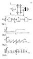
- Fig. 5 einen selbstgeführten Wechselrichter mit Gleichspannungszwischenkreis und Regelanordnung,
- Fig. 6 den zeitlichen Verlauf der Eingangsgleichspannung,
- Fig. 7 den zeitlichen Verlauf der Hilfsspannung und der Steuerspannung,
- Fig. 8 den zeitlichen Verlauf der Ausgangsspannung.
- 5 shows a self-commutated inverter with a DC link and control arrangement,
- 6 shows the time course of the DC input voltage,
- 7 shows the time course of the auxiliary voltage and the control voltage,
- 8 shows the time course of the output voltage.
In Fig. 5 ist ein selbstgeführter Wechselrichter mit Gleichspannungszwischenkreis und Regelanordnung dargestellt. Zwischen den Eingangsklemmen 1 und 2 des Zwischenkreises sind ein Stützkondensator 3 sowie ein Spannungsmeßgerät 15 geschaltet. Mit der Klemme 1 sind zünd- und löschbare Stromrichterventile 4 und 5 sowie mit der Klemme 2 zünd- und löschbare Stromrichterventile 6 und 7 verbunden. Am gemeinsamen Verbindungspunkt der Stromrichterventile 4 und 6 liegt die erste Klemme eines Verbrauchers 8 (z:.B. Motor) sowie am gemeinsamen Verbindungspunkt der Stromrichterventile 5 und 7 die zweite Klemme des Verbrauchers 8. Am Verbraucher 8 liegt die Ausgangsspannung des Wechselrichters U an. Zur Vereinfachung ist in Fig. 5 ein zweiphasiger Wechselrichter dargestellt, die Erfindung findet jedoch vorzugsweise bei dreiphasigen Wechselrichtern zur Speisung von Drehstrom-Asynchronmotoren Anwendung.5 shows a self-commutated inverter with a DC link and control arrangement. A supporting
Die zwischen den Klemmen 1 und 2 anliegende Eingangsgleichspannung UE des Zwischenkreises wird vom Spannungsmeßgerät 15 erfaßt, mit einem Faktor K bewertet und der Wert K . UE wird einem Multiplizierer 16 zugeleitet. Dem Multiplizierer 16 wird als weiterer Faktor die sägezahnförmige Hilfsspannung UB zugeführt. Die ausgangsseitige Hilfsspannung des Multiplizierers UH = UB . K . UE wird einer Additionsstelle 12 mit negativem Vorzeichen zugeführt. Der Additionsstelle 12 liegt mit positivem Vorzeichen die Steuerspannung UY an. Die Steuerspannung Uy kann bei einer gesteuerten Anordnung vorgegeben werden oder sie wird bei einer geregelten Anordnung mittels eines Strom-, bzw. Spannungs- bzw. Leistungsreglers gewonnen. Im Ausführungsbeispiel wird die Steuerspannung UY mit Hilfe eines Stromreglers 11 ermittelt, der eingangsseitig mit einer Additionsstelle 10 verbunden ist. Der Additionsstelle 10 liegen eingangsseitig mit positivem Vorzeichen ein Stromsollwert Us sowie mit negativem Vorzeichen ein Stromistwert UI an. Der Stromistwert U1 wird mit Hilfe eines in einer der Stromzuleitungen des Verbrauchers 8 angeordneten Strommeßgerätes 9 ermittelt.The DC input voltage U E present between the
Die Additionsstelle 12 ist ausgangsseitig mit einem Komparator 13 verbunden. Der Komparator 13 liefert ausgangsseitig Schaltbefehle S an einen Steuersatz 14, der Steuerbefehle Z zur Zündung bzw. Löschung der Stromrichterventile 4, 5, 6, 7 abgibt.The
Zur Beschreibung der Funktionsweise der erfindungsgemäßen Regelanordnung sind in den Figuren 6, 7, 8 die zeitlichen Verläufe der Eingangsgleichspannung UE des Wechselrichters, der sägezahnförmigen Hilfsspannung UH, der Steuerspannung UY sowie der Ausgangsspannung UA des Wechselrichters dargestellt. Wie aus Fig. 6 ersichtlich ist, steigt die Eingangsgleichspannung (Zwischenkreisspannung) UE aufgrund einer Störung zum Zeitpunkt t0 von einem konstanten Wert UE1 auf einen erhöhten Wert UE2 an. Diese Spannungserhöhung wird vom Spannungsmeßgerät 15 erfaßt und an den Multiplizierer 16 weitergegeben. Der Multiplizierer 16 bildet das Produkt UH = U B . K . UE und leitet es der Additionsstelle 12 zu. Die Amplitude der sägezahnförmigen Hilfsspannung UH steigt also vom Wert UH1 vor dem Zeitpunkt t0 auf den Wert UH2 nach dem Zeitpunkt t0, d.h. die Eingangsgleichspannung (Zwischenkreisspannung) UE wird als Störgröße in die Regelung so eingeführt, daß die Amplitude der Hilfsspannung proportional zur Eingangsgleichspannung ist.6, 7, 8 show the time profiles of the DC input voltage U E of the inverter, the sawtooth-shaped auxiliary voltage U H , the control voltage U Y and the output voltage U A of the inverter. As can be seen from FIG. 6, the input DC voltage (intermediate circuit voltage) U E rises from a constant value U E1 to an increased value U E2 due to a fault at time t 0 . This voltage increase is detected by the
Die Schaltbefehle S bzw. Steuerimpulse Z für die Stromrichterventile 4, 5, 6, 7 des Wechselrichters werden durch Schnittpunktbildung zwischen UH und UY gewonnen. Die Steuerspannung UY ist dabei proportional zum Grundschwingungssollwert der Ausgangsspannung UA und wird meist sinusförmig vorgegeben. Im Ausführungsbeispiel ist die Steuerspannung U zur Vereinfachung konstant angenommen. Die Hilfsspannung UH kann dreieckförmig, sägezahnförmig, trapezförmig usw. vorgegeben sein. Bei Auftreten eines Schnittpunktes zwischen der Anstiegsflanke von UH und der Steuerspannung UY erfolgt eine Löschung des gerade stromführenden Stromrichterventils, d.h. die Ausgangsspannung UA des Wechselrichters fällt auf den Wert 0 ab. Bei Auftreten eines Schnittpunktes zwischen der Abfallflanke von UH und der Steuerspannung U erfolgt eine Zündung eines der Stromrichterventile, d.h. die Ausgangsspannung UA steigt auf den Amplitudenwert UA1 (vor dem Zeitpunkt t0) bzw. auf den erhöhten Amplitudenwert UA2 (nach dem Zeitpunkt t0). Durch die Erhöhung der Amplitude der Hilfsspannung vom Wert UH1 auf den Wert U H2 ergeben sich steilere Anstiegsflanken der Hilfsspannung UH und damit eine kürzere Leitdauer der Stromrichterventile bzw. schmalere Pulsbreiten der Ausgangsspannung UA. Die Spannungs-Zeit-Flächen der einzelnen Pulse der Ausgangsspannung UA vor bzw. nach dem Zeitpunkt t0 bleiben dabei konstant, da die erhöhte Amplitude UA2 der Ausgangsspannung UA durch die Verkleinerung der Pulsbreite bzw. die verkürzte Leitdauer der Ventile kompensiert wird. Der Mittelwert der Ausgangsspannung
Claims (1)
Priority Applications (1)
| Application Number | Priority Date | Filing Date | Title |
|---|---|---|---|
| AT82103133T ATE13112T1 (en) | 1981-04-24 | 1982-04-14 | CONTROL ARRANGEMENT FOR A SELF-COMPATIENT INVERTER WITH D.C. LINK. |
Applications Claiming Priority (2)
| Application Number | Priority Date | Filing Date | Title |
|---|---|---|---|
| DE3116342 | 1981-04-24 | ||
| DE19813116342 DE3116342A1 (en) | 1981-04-24 | 1981-04-24 | "CONTROL ARRANGEMENT FOR A SELF-GUIDED INVERTER WITH A DC INTERMEDIATE CIRCUIT" |
Publications (3)
| Publication Number | Publication Date |
|---|---|
| EP0063745A2 true EP0063745A2 (en) | 1982-11-03 |
| EP0063745A3 EP0063745A3 (en) | 1983-06-29 |
| EP0063745B1 EP0063745B1 (en) | 1985-05-02 |
Family
ID=6130760
Family Applications (1)
| Application Number | Title | Priority Date | Filing Date |
|---|---|---|---|
| EP82103133A Expired EP0063745B1 (en) | 1981-04-24 | 1982-04-14 | Regulating device for a self piloted inverter with an intermediate d.c. circuit |
Country Status (3)
| Country | Link |
|---|---|
| EP (1) | EP0063745B1 (en) |
| AT (1) | ATE13112T1 (en) |
| DE (1) | DE3116342A1 (en) |
Cited By (2)
| Publication number | Priority date | Publication date | Assignee | Title |
|---|---|---|---|---|
| EP0073045A2 (en) * | 1981-08-21 | 1983-03-02 | Hitachi, Ltd. | Method of controlling an induction motor by a PWM inverter |
| EP0483447A2 (en) * | 1990-10-29 | 1992-05-06 | Hughes Aircraft Company | Pulse width modulated motor control system |
Citations (3)
| Publication number | Priority date | Publication date | Assignee | Title |
|---|---|---|---|---|
| FR1515719A (en) * | 1966-03-31 | 1968-03-01 | Bbc Brown Boveri & Cie | Method of controlling a static converter device |
| FR2107963A1 (en) * | 1970-09-25 | 1972-05-12 | Borg Warner | |
| FR2200669A1 (en) * | 1972-09-20 | 1974-04-19 | Bbc Brown Boveri & Cie |
-
1981
- 1981-04-24 DE DE19813116342 patent/DE3116342A1/en active Granted
-
1982
- 1982-04-14 EP EP82103133A patent/EP0063745B1/en not_active Expired
- 1982-04-14 AT AT82103133T patent/ATE13112T1/en not_active IP Right Cessation
Patent Citations (3)
| Publication number | Priority date | Publication date | Assignee | Title |
|---|---|---|---|---|
| FR1515719A (en) * | 1966-03-31 | 1968-03-01 | Bbc Brown Boveri & Cie | Method of controlling a static converter device |
| FR2107963A1 (en) * | 1970-09-25 | 1972-05-12 | Borg Warner | |
| FR2200669A1 (en) * | 1972-09-20 | 1974-04-19 | Bbc Brown Boveri & Cie |
Cited By (4)
| Publication number | Priority date | Publication date | Assignee | Title |
|---|---|---|---|---|
| EP0073045A2 (en) * | 1981-08-21 | 1983-03-02 | Hitachi, Ltd. | Method of controlling an induction motor by a PWM inverter |
| EP0073045A3 (en) * | 1981-08-21 | 1984-02-01 | Hitachi, Ltd. | Method of controlling an induction motor by a pwm inverter |
| EP0483447A2 (en) * | 1990-10-29 | 1992-05-06 | Hughes Aircraft Company | Pulse width modulated motor control system |
| EP0483447A3 (en) * | 1990-10-29 | 1992-06-17 | Hughes Aircraft Company | Pulse width modulated motor control system |
Also Published As
| Publication number | Publication date |
|---|---|
| DE3116342A1 (en) | 1982-11-18 |
| EP0063745B1 (en) | 1985-05-02 |
| EP0063745A3 (en) | 1983-06-29 |
| ATE13112T1 (en) | 1985-05-15 |
| DE3116342C2 (en) | 1988-11-10 |
Similar Documents
| Publication | Publication Date | Title |
|---|---|---|
| DE4208114C2 (en) | Control device for a bidirectional pulse width modulated converter | |
| AT403865B (en) | VOLTAGE CONVERSION DEVICE FOR A DC VOLTAGE CONSUMER | |
| EP0664613B1 (en) | Method and device for balancing the load on power semiconductor modules connected in parallel | |
| EP1157320A1 (en) | Method for generating a regulated direct voltage from an alternating voltage and power supply device for implementing said | |
| DE2143622A1 (en) | DC arc welder | |
| EP0063745B1 (en) | Regulating device for a self piloted inverter with an intermediate d.c. circuit | |
| EP0252898A2 (en) | Three-phase induction motor drive with frequency converter control | |
| DE2217023C3 (en) | Feed circuit for a direct current consumer fed by a single or multi-phase alternating current source | |
| DE3721631C2 (en) | ||
| DE2151019C3 (en) | Process for regulating the current drawn from or supplied to an alternating current network and arrangement for carrying out the process | |
| DE3130356C2 (en) | Control arrangement for the even load distribution of two power supply devices connected in parallel on the output side | |
| DE3731555C1 (en) | Induction heating device with a setting preset controlled by the actual value | |
| DE2907580A1 (en) | METHOD AND ARRANGEMENT FOR GENERATING A SMOOTHED VOLTAGE FROM THREE-PHASE | |
| EP3871329B1 (en) | Converter, drive system having converter, and method for operating a converter | |
| DE1613775C3 (en) | Arrangement for controlling the speed of an AC motor operated by an inverter | |
| EP0330055B1 (en) | Process for the symmetrical subdivision of a dc voltage in series with a voltage divider consisting of n capacitors, and circuitry for carrying out the process | |
| DE102020129614B3 (en) | Voltage regulation circuit and method of operating a voltage regulation circuit | |
| DE19848728B4 (en) | Converter device for a DC machine | |
| DE3224301C2 (en) | ||
| DE3223655A1 (en) | DEVICE FOR CONTROLLING AN AC INDUCTION MOTOR | |
| DE3239310A1 (en) | Control device for a converter having a DC intermediate circuit | |
| EP1298781A1 (en) | Power converter device and method for adjusting a variable DC voltage | |
| AT514684B1 (en) | Method for controlling a rectifier circuit | |
| DE2621763A1 (en) | Blocking transformer power pack operation - controls differential amplifier input voltages by different variables with amplifier output voltage control | |
| DE2340705C3 (en) | Control method for starting up a direct current motor fed by a controllable and extinguishable converter |
Legal Events
| Date | Code | Title | Description |
|---|---|---|---|
| PUAI | Public reference made under article 153(3) epc to a published international application that has entered the european phase |
Free format text: ORIGINAL CODE: 0009012 |
|
| AK | Designated contracting states |
Designated state(s): AT BE FR GB IT NL SE |
|
| PUAL | Search report despatched |
Free format text: ORIGINAL CODE: 0009013 |
|
| AK | Designated contracting states |
Designated state(s): AT BE FR GB IT NL SE |
|
| 17P | Request for examination filed |
Effective date: 19830720 |
|
| ITF | It: translation for a ep patent filed |
Owner name: DE DOMINICIS & MAYER S.R.L. |
|
| GRAA | (expected) grant |
Free format text: ORIGINAL CODE: 0009210 |
|
| AK | Designated contracting states |
Designated state(s): AT BE FR GB IT NL SE |
|
| REF | Corresponds to: |
Ref document number: 13112 Country of ref document: AT Date of ref document: 19850515 Kind code of ref document: T |
|
| ET | Fr: translation filed | ||
| PGFP | Annual fee paid to national office [announced via postgrant information from national office to epo] |
Ref country code: AT Payment date: 19860226 Year of fee payment: 5 |
|
| PLBE | No opposition filed within time limit |
Free format text: ORIGINAL CODE: 0009261 |
|
| STAA | Information on the status of an ep patent application or granted ep patent |
Free format text: STATUS: NO OPPOSITION FILED WITHIN TIME LIMIT |
|
| 26N | No opposition filed | ||
| PG25 | Lapsed in a contracting state [announced via postgrant information from national office to epo] |
Ref country code: BE Effective date: 19860430 |
|
| BERE | Be: lapsed |
Owner name: BROWN BOVERI & CIE A.G. Effective date: 19860430 |
|
| PGFP | Annual fee paid to national office [announced via postgrant information from national office to epo] |
Ref country code: NL Payment date: 19870430 Year of fee payment: 6 |
|
| PG25 | Lapsed in a contracting state [announced via postgrant information from national office to epo] |
Ref country code: AT Effective date: 19880414 |
|
| PG25 | Lapsed in a contracting state [announced via postgrant information from national office to epo] |
Ref country code: SE Effective date: 19880415 |
|
| PG25 | Lapsed in a contracting state [announced via postgrant information from national office to epo] |
Ref country code: NL Effective date: 19881101 |
|
| PG25 | Lapsed in a contracting state [announced via postgrant information from national office to epo] |
Ref country code: GB Effective date: 19881121 |
|
| NLV4 | Nl: lapsed or anulled due to non-payment of the annual fee | ||
| GBPC | Gb: european patent ceased through non-payment of renewal fee | ||
| PG25 | Lapsed in a contracting state [announced via postgrant information from national office to epo] |
Ref country code: FR Free format text: LAPSE BECAUSE OF NON-PAYMENT OF DUE FEES Effective date: 19881229 |
|
| REG | Reference to a national code |
Ref country code: FR Ref legal event code: ST |
|
| EUG | Se: european patent has lapsed |
Ref document number: 82103133.3 Effective date: 19890726 |