EP0064787A2 - Methods for timing pigeon races - Google Patents
Methods for timing pigeon races Download PDFInfo
- Publication number
- EP0064787A2 EP0064787A2 EP82200491A EP82200491A EP0064787A2 EP 0064787 A2 EP0064787 A2 EP 0064787A2 EP 82200491 A EP82200491 A EP 82200491A EP 82200491 A EP82200491 A EP 82200491A EP 0064787 A2 EP0064787 A2 EP 0064787A2
- Authority
- EP
- European Patent Office
- Prior art keywords
- pigeon
- recorder
- carrier
- data
- ring
- Prior art date
- Legal status (The legal status is an assumption and is not a legal conclusion. Google has not performed a legal analysis and makes no representation as to the accuracy of the status listed.)
- Granted
Links
Images


Classifications
-
- G—PHYSICS
- G07—CHECKING-DEVICES
- G07C—TIME OR ATTENDANCE REGISTERS; REGISTERING OR INDICATING THE WORKING OF MACHINES; GENERATING RANDOM NUMBERS; VOTING OR LOTTERY APPARATUS; ARRANGEMENTS, SYSTEMS OR APPARATUS FOR CHECKING NOT PROVIDED FOR ELSEWHERE
- G07C1/00—Registering, indicating or recording the time of events or elapsed time, e.g. time-recorders for work people
- G07C1/22—Registering, indicating or recording the time of events or elapsed time, e.g. time-recorders for work people in connection with sports or games
- G07C1/26—Pigeon-timing or like equipment
Landscapes
- Physics & Mathematics (AREA)
- General Physics & Mathematics (AREA)
- Time Recorders, Dirve Recorders, Access Control (AREA)
Abstract
Description
- In pigeon-flying it is usual to provide the pigeons, which are to compete in a race, with a rubber-ring before putting them into a shipping wicker. In these races pigeon-fanciers can earn sometimes fat prices when their pigeon comes back as the first one, and if they have staked moreover on a pigeon an amount of money being a multiple of the normal stake. Accordingly the race-rules are such that fraud is excluded. Therefore, only the race-commissioner, with the aid, if any, of a numer of assistants, is entitled to ring the race-pigeons. To this end he uses a special pair of ring pincers, by means of which the ring is expanded. In that situation the pincers with ring are slid over the pigeon's foot with the four toes being kept straight, after which the pincers are pinced together, so that the ring can be removed from the pincers rather easily, and, after removal of the pincers, is left on the foot. This procedure is very laborious and takes many hours to ring about 100 pigeons.
- The rubber ring bears a competition number and is always slid on the "free foot", this term being chosen to distinguish from the foot with the identification ring, which the pigeon soon receives after its birth, already when it is still a young. This ring was in older times of aluminum, at present of plastics.
- The race-commissioner's assistant accompanies the wickered pigeons at their journey with truck or railway-van to the place of destination in inland or abroad, which serves as a start point for the pigeons. The commissioner's assistant notes the time on which the pigeons are released, and passes this on to the race-commisioner by telephone or by cablegram.
- When the pigeons come home from the race, the pigeon's owner takes the race-ring from the foot, puts the ring in the relevant aperture in the clock (recorder) which, besides, is sealed. The ring drops into a space defined by one of the recesses in a cog-wheel being provided along its circumference with 36 recesses and mounted on the axle of the clock-work. The pigeon-fancier should now give the cog-wheel a short turn (1/36 of a complete circle arc = 10 ) whereby the recess with ring is shoven up by one location and will lie above an aperture in the bottom plate of the cog-wheel. This aperture leads to a collecting tray for rings, wherein the ring will fall, whereas simultaneously the time indicated by the clock-work, during the turning of the cog-wheel, is recorded on a registration roll. By this the pigeon is "clocked-in". So with one
clock 36 pigeons can be clocked. - When the competition is finished, the pigeon-fancier brings his clock to the club-room, where the race-commissioner starts stopping the clocks: the clocks are all depressed, the sealing is broken, whereafter the registration roll is taken out of the clock. Then the flight time is calculated and also the average velocity of each individual pigeon, the order of arrival of the pigeons, whilst considering the coordinates. These areiie meters which must be added to or subtracted from the race-distance towards a central point (for example a church-tower) in the residence of the club to make a correction for the fact that pigeons of some club members have to cover a small distance more and other pigeons a small distance less. Further the prize-money must be calculated, which the first arriving pigeons have earned for their bosses, because the stakes for the pigeons can differ and also because age, sex, "civil status" of the pigeons must be considered as handicaps. Moreover the clocks must be compared with a master clock in the club-room and any differences must be cleared in the calculation. The ciphering or calculating work is therefore after finishing of the competition, enormous. In spite of the use of pocket mini-computers, this work asks for many hours.
- Still an objection adhering to the conventional pigeon competitive sport is the heavy weight of the clocks. A clock has a weight of about 7 kg. Some pigeon votaries posses a great number of pigeons, divided over two or more pigeon houses. It may happen that from each house a few pigeons join in the competition. This makes it necessary during the arrival of the pigeons to walk with the clock from one pigeon house to the other.
- To alleviate these and other difficulties, the invention provides an electronic pigeon-recorder, cooperating with a data-carrier bearing a competition number - if any in code form - on or in it, the cooperation between the recorder and the data-carrier being such that the former registers electronically on the latter a time-observation originating from a built-in clock-work, there being provided in the recorder a collecting room for the temporary collecting of the data-carriers, thus provided with the two data being 1. most essential for pigeon-flying, in abeyance of further processing of these data-carriers with data in a micro-processor.
- It is thought that the disadvantages mentioned of the present competition system can be avoided by designing a simpler system whilst making use of modern electronics, with which the end result can be found faster. An additional advantage is that the new pigeon recorder is lighter in weight. In the following paragraphs some main systems together with a few alternatives will be discussed, in which systems the objections mentioned have been met. The system will be discussed on the order of increasing growth of data-processing.
- In this system a pigeon, taking part of a competition, gets, as usual, a rubber race-ring shoven over its foot, which ring carries on its circumference a magnetic susceptible strip, that is sent along in a blanc, magnetically virgin or non-magnetized state.
- After the pigeon's entrance said ring is stripped off the pigeon's foot by its boss and is thrown through an appropriate aperture in the pigeon recorder. Said recorder is no longer a traditional clock, but an aperture, in which the heavy mecanical parts have largely been replaced by light weight electronic parts. The clockwork itself is still present, but also in a lighter embodiment, for example in a numerical mode.
- The new pigeon recorder comprises therefore among other elements: a magnetic wiping head and a writing head. When the ring is thrown by the pigeon-fancier through an opening in the recorder, it lands on a rotatable disc-shaped ring-holder or the like, which rotates the ring along the wiping head and then along the writing head. In this way the previous magnetic registration or, if any, a magnetic registration, picked up casually by the pigeon flying home, is wiped, and the time-signalling of the internal clockwork is registered via the writing head in a magnetic code on the magnetic strip. Hereafter the ring drops into a collecting tray.
- When the competition is finished, the pigeon-fanciers hand in their recorders. The race-commissioner depresses the clocks, breaks the seals and collets the rings. The competition number is read visually and noted and the ring is introduced immediately thereafter into a magnetic reading apparatus for decoding the magnetic code, so that the point of time, on which the ring concerned was "clocked-in", becomes known. The reading apparatus can be coupled to or is part of a data processing computer, so that the decoded time-observations a=e stored in the memory, in which also other significant data have been or are being introduced, like distance, point of time for setting free, competition numbers, identification numbers, coordinates, wind force and directions, name proprietor, previous performances of the winning pigeons, sums of money staked,handicaps,special stakes (multiplying factor) from which finally the order and the prizepayments are calculated by the computer, whereas on said list-of-results also the input data are stated, of course. All this is effected by a very extensive computer. It is possible, however, to content oneself with a simpler machine and to have the race-commissioner also done some calculation work.
- The advantage of this embodiment, in which still much handwork has to be done, is that brainwork is strongly simplified, in that via the magnetic time code provided on the ring, this information is suitable for automatic processing, whereby the calculation work, if any, can be safed. The recorder too can be carried out mecanically with regard to the traditional clock, essentially simpler. The apparatus is entirely tamper-proof. The recorder to be used by the pigeon-fancier is easy and foolproof, whereas the duties which the computer has to fulfil, can be extended gradually from a simpler reading apparatus for reading the magnetic time code to a computer with a bulky memory, in which not only are introduced the data valid for a certain competition, but also the data of previous competitions. Before procuring an expensive computer it would suffice to connect the recorder to programmable table computer apparatus, which the club is the proprietor of. When one wants more - information to be processed respectively when one wants to do less calculation work, a larger computer with a larger memory is to be considered, which can be controlled together with a number of sister unions in the neighbourhood. Finally if it is wanted to set eyes on all the information, just mentioned, it is necessary to install a data bank at rural level, to which each union is connected via a terminal.
- A still remaining complication is the ringing of the pigeons and the mecanism of rotating or conveying the ring on the ring-holder.
- Also for this problem this application offers a solution. Part of the problem vanishes by taking an additional ring.
- Such a ring can be provided with all pigeons, regardless their age, thus also with old pigeons whose feet no longer grow in thickness, so that the new ring could be removed from the foot. Notwithstanding, fraud is excluded since the code to be provided is only known to the race-commissioner and is provided by him and is illegible and invisible for the race-participants. If in spite thereof they consider it undesirable that the additional ring can be removed from the foot of all pigeons, the ring can be pinced on one or more locations.
- In the long run, thus with each new brood, the new-born pigeon-young can be ringed with an identification ring of larger size than usual, so that room is left thereon for positioning a code. In this way the identification ring can also be used as race-ring in that thereon the code valid for a certain competition is provided.
- Anyway by these measures it is not necessary to ring the pigeon prior to their wickering which sofar has led to a very cumbersome treatment.
- All these data-carriers of various "clocked" pigeons collect themselves in a collecting tray, which only, when opening the recorder by the race-commissioner, become accessible.
- la. The cheapest one of both embodiments is to put the individual data-carrier in a programmable pocket mini-computer, which can outreal these carriers. On a card, the program to be executed can already be encoded - so as to take the problems off the user in this respect too. The user can even introduce (or inreal) certain data into the pocket mini-computer which are important for the calculation desired.
- Pigeon-fanciers who avail of such pocket. mini-computer are still relatively cheap off.
- lb. A more expensive embodiment destined for people who do not avail of a programmable pocket mini-computer, is to connect to the recorder a separate calculator-module. The calculator-module comprises an entrance, through which significant data are stored to a memory, for example the starting-time, or unloading time, distance etc., and furtheron the calculator proper and a display.
- The calculator is connected to a processor in the recorder- module. The calculator also receives the data stored in the memory. The information calculated from these two kinds of data is supplied back to the memory on the one hand, and to the display: screen or registration strip, on the other hand.
- Also in this extended embodiment there is still question of a light weight recorder having a weight of a few hundred grams. The conventional pigeon-clock weighs 7 kg. and costs ± f 700,= For the many homing pigeon-votaries, 700.00 in number in the world, this new apparatus will meet with a long felt need.
- In the above main-system the magnetic code has been the middle-point of the discussion. This code, which bears a magnetic race- . code, produces, if put in a recorder, a signal causing the registration of a time observation. However, it is likewise possible to render the magnetic area on the ring double-tracked. Said one track bears the competition code of the pigeon and said other track will receive the time-signalling.
- A disadvantage adhering to this magnetic system (System I)is that the magnetic competition code on the ring, during the flight of the pigeons, can be disturbed seriously by strong magnetic fields. However, in regions where high tension pillons do not occur, this system satisfies excellently and can be used in practice, whereas regularly new alloys are being developed- having better magnetic properties.
- The objections adhering to the above rubber ring system with magnetic code system (ft) can be met partly by means of a barcode system, consisting of a plurality of transparent and opaque bars, in which,a code has been incorporated. Since there is in such a code an optical contrast, the bars can be sensed in an optical way by means of a reading pencil. The equipment which must process said information in the next step, is expensive and bulky and should be procured in union-/or in a wider context.
- Both identification number of the pigeon and the competition code used in a competition can be fixed in barcode shape on a ring. The barcode, however, is less ambulant than the magnetic code. That means that a barcode, if applied, cannot be wiped off and be registered in a simple manner. Therefore this code is not suited for competitions, since the competitive sport wants a code which can easily be modified.
- When, however, the competitive barcode is applied on a self-adhesive tape (the adhesive must be water-repellent for reasons evident per sd or on a easily bendable tape, there are on the tape two kinds of code-carriers which can easily be applied around and removed from the pigeons foot. The barcode sticker can be applied on a separate, but permanent ring (thus as a second ring) or even on the identification ring - if it is not too narrow. The metal tape with barcode can easily be bent by hand or by means of pincers around the pigeon's foot.
- Have therewith the objections adhering to the ringing with rubber rings come back again entirely? No. The rubber ring previously must be expanded widely with a pair of pincers and must be shoven over the foot, which is a laborious work. Applying the barcode sticker is a simple act and the same is true more or less for bending thermetal tape. Although the two kinds-of barcode carriers do not constitute a ring closed in itself, there is no risk of loosing the barcode sticker or the metal tape. Here too fraud is excluded, because the code being mentioned on these carriers is only known to the race-commissioner. When the race-pigeon drops in, the pigeon-fancier must remove the barcode carrier from the pigeon's foot and stick the sticker on an internal data-carrier. The code-carrier is put next in a recorder. An optical eye incorporated records that the code-carrier is thrown through a slot and produces a signal so that a time observation can be done, which is recorded on a magnetic card, or on the magnetic susceptible zone of the carrier of the sticker. The barcode is not sensed within the recorder because this would require a too expensive apparatus.
- At the end of the competition the barcode carriers collected at the bottom of the recorder are removed from the apparatus by the race-commissioner and offered in the order present to the computer for reading (outrealing) together with a magnetic collecting card. Accordingly the computer tells which pigeon at which point of time is entered and is clocked-in. If the time-signalling has occurred on the sticker or tape, the processing of the information is much simpler for the computer.
- The ideal system is formed by a combination of the magnetic code and the barcode. On the pigeon ring (second or identification ring) the fixed barcode of the identification is applied on a suitable area, whereas on an adjacent area the competition number in code-form is applied optically or magnetically. If this is done optically, a barcode sticker or the like is used. Two optical codes behind each other have the advantage that the race-commissioner can read both numbers with one op÷ tical reading pencil which the union is availing of. Also the combination I of magnetic and optical codes has said same advantage , viz. a coupling between identification and competition numbers.
- In the above embodiments there has occurred a gradual reduction of calculation and hand works.
- The electronic pigeon recorder according to the invention distinguishes itself of the conventional mecanical pigeon clocks in that it is equipped not only with a clock and a data carrier, but also with means for transforming the data registered with the recorder,into a form suitable for automatic processing, whereby the data carrier, being, after passing the recorder, ready for automatic processing, comprises the two data being most essential for the pigeon-flying, viz. the competition number assigned for the race and the time-observation indicated by the clockwork after the race.
- The embodiment based on System I. is characterised in that the data-carrier is formed by a rubber race-ring having along its circumference a magnetically susceptible carrier which, after inserting the data carrier into the recorder, cooperates with a magneting wiping head and writing head provided in the recorder, for recording a time observation into the magnetic susceptible area.
- An embodiment based upon System II is characterised in that on the permanent foot ring is provided a barcode corresponding to the pigeon's identification number and on the same ring or another one a removable barcode corresponding to a competition number assigned to a pigeon, whereby the race-barcode after the flight is provided on another internal carrier with a magnetic zone, and furtheron an optical reading means is provided for sensing the barcode, whereas the pigeon recorder itself is equipped with an optical eye (photo cell). In a further alternative the removable barcode is provided on a carrier with adhesive sub-layer or on a bendable metallic tape.
- Preferentially the pigeon recorder according to the invention consists of the combination of the magnetic system (System I) and the optical system (system II).
- The invention is also related to a combination of the present pigeon recorder with its own display unit, including a simple reading device, and further to a combination of the present pigeon recorder with its own calculator, of course including an entry for data.
- It will be clear that the carriers with information about competition number and time observation, though they do not constitute a fixed constituent of the recorder, yet should be considered as ambulant part and in the afore mentioned description have been considered as such. Owing to their ambulant nature they can be manufactured entirely separated from the recorder, and their manufacture can or must be accomodated with another factory. For that reason a separate protection is claimed for the information carriers used in the recorder accoring to the invention.
- In the preceding chapters a magnetic and/or optical application is given; in this section of the application an electrical application is given, in which passive circuit components are playing a role, such as resistor, capacitor and inductor, completed by electronic accessories.
- The internal data carrier according to the invention is characterised in that the data recorder is formed as a passive circuit-element and cooperates with a pigeon recorder comprising a housing, in which an electric current circuit, including a power-pack for electric current, a registration unit, registering the time and the like, an operative amplifier and a numerical display and further an entry-opening, an entry-room connected to the electric current circuit and a collecting room, whereby the electric current circuit is activated when inserting the passive circuit element into the entry-room, whereas means are provided for transmitting the circuit-element from the entry-room to the collecting room. In the collecting-room the passive circuit components of all pigeons which have been "clocked-in" within the time-period set, come together, said room being emptied by the race-commissioner in the club's room. The components are controlled by measuring their value in a current circuit or measuring bridge, if ever this has not already been done in the registration unit of the data recorder itself. It is therefore clear that in principle the data recorder can initially be kept simple and that the functions, saved therein, can be accomodated in a more extended device, disposed in the club's room. Gradually more facilities can be imparted to the private data recorder of the pigeon-fancier, and those of the club's data recorder can be reduced, or be extended with new functions.
- An advantageous and very simple embodiment too of the electric/electronic application is a data-carrier, in which the passive circuit element is a resistor. Such a mini-resistor that is carried by the pigeon during its transportation trip and during its flight back again, is taken from the pigeon after its arrival by the pigeon-fancier, and put by him into the data recorder. In electronics mini- or print-resistors are in use having very small sizes, which are particularly useful for the present purpose. For example diameter φ = 2 mm and length L = 4 mm. These resistors have a resistance range from ion to 1MΩ. These resistance values are exact within 1%; for example R = 98.674.0 ± 1% tolerance. This means that the resistors must be divided into sub-ranges. Theoretically there are 582 possibilities, in practice less. If there would be a race every week, the total number of possibilities would suffice for 10 years. Everytime another resistance value can be chosen ensuring reliability for every flight. Statistically the 580 different resistance values will not come to their turn one by one. In one month a certain resistance sub-range could even be used twice, but anybody who fosters fraudulent intentions cannot predict this. The chance of fraud is therefore (also on this system) excluded.
- If there is need for a larger number of possibilities, their quantity can be raised by offering not only a choice out of various resistance sub-ranges, but also out of a certain colourcode , or a choice out of other sizes of these print- or mini-resistors, so that again other resistance-values can be obtained. Apart therefrom letter and/or cipher combinations can be applied on the outer surface of the resistor.
- Similar advantages and possibilities can be obtained when instead of a resistive circuit component, a capacitive circuit component is applied.
- Combinations of the various kinds of circuit components are also possible.
- The data recorder is constructed such that after the circuit component is taken off the pigeon and is put via the entry opening into the entry-room, a depression-key is to be activated in order to include the circuit component really into the electric current circuit and to close the latter, so that the circuit becomes operative such that the exact time of arrival of the pigeon, that means the time at which the circuit component was put into the entry-room and the depression-key was activated, is registered. This can be shown on a (display)-screen registered on a paper-roll or strip, or on a magnetic strip or tape, so that they can be used later for automatic processing of all individual data of the pigeons f the club members by a computer, if any, arranged in the club's room.-Thereby the minute calculation work, that must be executed after finishing the competition by a calculating person for
Dutch f 0,24 the pigeon, which would maintain the suspense for some additional hours after the end of the flight, can be abandoned, which means a considerable saving of costs. - Also for the race-ring this new form of registration has consequences. As stated in the preceding chapters, it is the intention of the new system to get rid of the cumbersome, time-consuming "ringing" of the pigeons prior to their "wickering". For this ringing it is necessary to expand a rubber ring by means of a pair of ring-pincers and to slip the ring over the widely spread toes of the pigeon's foot. Sliding a small resistor in a thickened portion of the fixed ring means an essential alleviation of the race-commissioner's work.
- In a similar way a mini-capacitor, having for example aflat-round shape and being of the plate-capacitor type, can be inserted in a pocket in the wall of the pigeon-ring, said pocket being executed as a kind of letter-box.
- In a practical embodiment of the race=ring according to the invention, the passive circuit-element is inserted under spring-bias into a ferrule or pocket, which can be closed to keep the element under mecanical tension. In this way the resistor included in the hollow space of the wall of the pigeon-ring is shielded from moisture, when a pigeon for drinking on its way home, steps with its feet in a pool of water. Apart therefrom the spring is intended to press the resistor a little outwards so that, after the closurecap is turned or swung away, the protruding end of the resistor can be seized easily by the proprietor. Also for that reason there is a need for a closing means to close the ferrule or the pocket in the pigeon-ring and to lock the circuit-element against spring-bias.
- In order to introduce a new system in the pigeon-flying, the circuit-component must be formed such, that it can be sent along with older pigeons, which from their birth are already ringed with an identification ring, not being provided with a facility to accomnodate thereon a circuit fcomponent. This difficulty can be met by securing a ferrule or the like, provided with a circuit-element, to the pigeon's foot, by means of a springing clip.
- The mecanical pigeon recorder can be replaced by an electronic data coupler, having the dimensions of a pocket-mini-com puter. This apparatus does no longer store the competition ring, but registers the secret competition number, different for each pigeon, which is taken along by the pigeon on its flight. This number can only become known to the pigeon-fancier, after the pigeon has come home.
- The competition number can be read visually and be transmitted to the pigeon recorder indirectly via a key-board or directly via a code-reader. This number together with the exact time of entry (from the built-in real-time clock) is stored into the memory.
- From the introduced release- and arrival times and the start-and home-coordinates, the processor can determine for the pigeon-fancier the flight velocity. This item can be stored into a memory and can be reproduced via a display. This can be realised with an electronic pigeon recorder, comprising input means for introducing flight data (clock-time, competition number, identification number etc.), a clockwork, whereby the signals of the input means and the clock-work are stored into the memory, after being processed, if any, in a processor placed before the memory, whereas the data stored into the memory can be called on for representation on a display.(The pigeon-fancier can call up all values, but he himself can modify nothing. Besides, each input is fixed with its own entry-time. In the club-room, or at home, the recorder can be connected, via a data link, to a host-computer, read (outrealed) and wiped out. The central host-computer or a terminal thereof, collects all competition numbers with associated times and coordinates. Previously, during "wickering" the pigeons, said competition numbers have been coupled to the pigeon's ring number. This information together with the coordinates of the pigeon-loft and the data of the proprietor is stored in the central computer.
- To restrict on the occasion of big flights the number of ciphers of the race-number, the recorder can even get a proprietor number or letter, which is coupled to the competition number, then there must be taken care that per proprietor no double competition numbers can occur. Further the number of possible combinations must be sufficient large to make the chance on "good gambling" as small as possible. It is meant herewith that the pigeon-fancier depresses an arbitray number on the key board at a too early moment. It follows that during wickering of the pigeons, no subsequent numbers may be used. Otherwise the flutter would become quite simple when one or two pigeons have already come in.
- A modification in the release-time can simply-be taken along in the calculations. The calculating and the arranging of the results can be done in a simple and especially fast manner, with the computer. The results are virtually immediately knwon after the flight.
- The new system can be introduced gradually. The number can always be stored on a small bit of paper in a conventional computer. The data of arrival ascertained with the electronic recorder can still be processed by hand. The automatic calculation and storage of the flight data make this work much easier.
- The number of pigeons that can be recorded by each recorder, is only dependent on the available room in the memory, which can easily be extended to a few hundreds of pigeons. In this system use can be made successfully of an external or internal data-carrier characterized in that the carrier, during the race, is taken along on the pigeon's foot as a vane, which is formed by overlapping the extremities of a narrow strip wrapped around a pigeon's foot and by sticking them to each other or heat-sealing them together, and in that the carrier cooperates with an electronic pigeon recorder, comprising input means for introducing flight data (clock-time, competition number, identification number), a clock-work, whereby the signals of the input means and the clock-work are stored into the memory, after being processed, if any, in a processor placed before the memory, whereas the data stored into the memory can be called-in for representation on a display.
- Preferentially a magnetic core is provided between the overlapping . extremities of the ribbon-shaped strip.
- Introduction: the electronic pigeon recorder requires a well-readable ring, whereas in the wickering of the pigeon still much time can be won. The pigeon's foot receives by means of a special pair of pincers a kind of numbered vane. This pair of pincers is characterised in that said pair of pincers comprises a cutting means and a reel on which is wound a roll of flexible material, which is provided on one face with an adhesive, or is heat-sealable, said material being conducted such that a pigeon's foot is wrapped with extending overlapping extremities to form a vane acting as code-carrier.
- Upon this vane high demands are made in respect of "pigeon-friendliness", durability and readability. For this -vane use can be made of plastics tape (adhesive or heat-sealable). This can be uninterruptedly taken from ;.a roll or by way of individual stickers. The ribbon may not irritate the pigeon's foot, so that if an adhesive tape is chosen, this tape may not stick to the foot, as a plaster does, It can be encoded beforehand or can be provided with codes during the ringing operation. Such pair of pincers is according to the invention characterized by an encoding device, arranged to apply a code on the vane to be formed during the adhering of the overlapping extremities.
- The identification number is to be coupled with the ring number for the later processing. This has to be done as automatically as possible. It is to be preferred to provide the pigeon-ring with an automatic code, for example a bar-code, so that it can be read with a code-reader. To this end the wickering-man will have to brush the correct zone of the ring with .a- reading means. A self-seeking reading means is asking a little too much for the time being. Also in the absence of a code-reader (decoder) or coder, the number can simply be read and be introduced via a key-board.
- The competition-number can be applied in visual ciphers and/or in a code readable by machines. The code can be applied on the tape beforehand but for establishing a coupling during the ringing operation, it must then be machine-readable for the ring-pincers. If it is provided during the ringing operation, it can be determined internally. These codes may not be applied in a predictable order, but in a secret order, differing for each competition. There must be an order anyway, since, this is the simplest manner to avoid doublures. The fact that the competition number is known to the pigeon-fancier is the proof that the pigeon has arrived.
- This apparatus has to be rigidly mounted on the table to give the wickering-man both hands free for holding the pigeon. After bringing the pincers around the pigeon's foot, the latter will automatically be provided with a numbered race-vane. Thereafter the number of the pigeon-ring can be read by a code-reader (decoder). The wickering-man has to keep the decoder near the encoded part of the ring. Reading is necessary for the coupling of the numbers. The numbers are stored in order to be used in the central computer for the processing of the flight results.
- Further the vane can also comprise a magnet core. Accordingly the pair of pincers is characterised by means to provide a magnetic core between the overlapping extremities during adhering said extremities together.
- Although the system heretofore described has, in respect to the conventional system, many advantages, viz. it is cheaper and lighter in weight, it processes without difficulty all kinds of data, and it is easy to be manufactured, there is still one important wish, which, on introducing electronics in the pigeon-flying, is not yet fulfilled. This concerns the wish that the time-registration of the competitive pigeons should not be dependent on the point of time at which the pigeon is caught and its ring is put in the clock (or recorder). Therefore, the system should be perfected such that the pigeon, if it were, clocks-in itself. But anyway, it must become such, that as the pigeon is settling itself on the landing-platform, its time is fixed.
- Applicant has indeed been able to perfect this system in the above manner, which can be realised in a device for recording the time or arrival and identification data of homing pigeons participating in a race, comprising a pigeon recorder, cooperating with means arranged on the landing-platform of the pigeon-loft, such that the point of time at which these means are passed by the pigeon, can be fixed in the pigeon recorder without it being necessary to have first the pigeon caught.
- In a first embodiment there are disposed on the landing-platform photocells which the pigeon has to pass after settling itself on its way to the entry-gate of the pigeon-loft, which produces a signal, that in the recorder transmits a time-signalling of the clockwork to the memory and is stored therein for the time being. At the same time the photocells become inactive and the entry-gate is blocked. Thereafter - in a quiet ambiance - the pigeon can be caught and its race-number can be read, or the race-ring should be fetched from the pigeon's foot, etc. and put into the clock, after which the time noted provisionally becomes definitive. All this time the device is blocked. The insertion of the code abolishes said blocking. This embodiment'; is characterised in that the means on the landing-platform consist of two or more photocells, which, when the pigeon passes the connection line between two cells, supply a signal to the pigeon recorder so that the passing time is stored by the clockwork in the memory and the device is locked untill the moment that the pigeon is cuaght and the race-ring itself or the data carried by it can be supplied to the pigeon recorder, whereafter the blocking of the device is abolished.
- It can be useful when more optical eyes (photocells) watch the arrival of the pigeon. Accordingly two or more photocells are also mounted at the location of the extension of the landing-platform behind the entry-gate or -gates, which cells cooperate with the cells in front of the entry-gate or -gates.
- In a second embodiment the means of the landing-platform are of magnetic nature and also destined for cooperation with magnetic means on the foot of the competitive pigeon. Two possibilities can be discerned. On the one hand the magnetic means on the landing-platform include a magnetic loop as primary circuit, cooperating with a secondary circuit, carried by the pigeon.
- The race-set for a competitive pigeon to be used in the device just described is according to the invention constructed as a secondary circuit, including a rectifier, an interruptor, a relay with soft-iron pin, cooperating with a code-carrier, likewise carried by the pigeon.
- On the other hand - instead of the magnetic loop - the means on the landing-platform include a magnet, cooperating directly or indirectly with a code-carrier, carried by the pigeon. The magnet can be constituted as a permanent magnet or as an electro-magnet. Therefore in the first place, the magnetc means on the landing-platform include a permanent magnet, being movable in a direction transversely to the horizontal depth direction of the platform, which magnet is able to attract a soft-iron plate adhering to the race-ring and carried along by the pigeon, and to hold said plate, while the pigeon walks further to an entry-gate at the end of the landing-platform. The soft-iron plate acting as code-carrier, is in this manner displaced by shearing from one permanent magnet to the other permenent magnet, which, to this end, has to be stronger than the first magnet.
- Preferentially the permanent magnet on the landing-platform is mounted to a string or the like which strings allows inward deflection-of the magnet on the string.
- The race-ring which can be used in this device, is according to the invention made of an a-magnetic material, for example plastics, whereby in the wall thereof a magnetic core is included.
- The soft-iron code-carrier transferred to the slidable permanent magent is taken from the magnet by the pigeon-fancier and the code is then read (a directly readable number or an encoded number in the form of bars or the like) and introduced into the recorder, so that the point of time concerned for the pigeon in question is fixed as time of arrival. Since the magnet is more or less bound to a fixed location, the magnet core in the plastic ring must point to or face said magnet. To prevent any rotating of the ring, the gap between ring and pigeon's foot can be filled with for example foam rubber or any other suited material. Secondly the magnetic means on the landing-platform include an electro-magnet being mounted below the landing-platform and cooperating indirectly and temporarily with a code-carrier.
- The race-set for a competitive pigeon to be used in the device comprises a magnetic core, a code-carrier and a soft-iron pin. In an alternative embodiment the race-set is modified such that this set holds the code-carrier not magnetically, but mecanically. In this embodiment the electro-magnet arranged below the landing-platform operates the soft-iron pin such that the code-carrier of the magnetic core passes over to the soft-iron pin.
- The cooperation is temporarily, because when the electro-magnet is de-energized, the code-carrier is released by the pin and falls on the landing-platform. The energizing of the strong electro-magnet can ¡ be actuated by the pigeon itself. To this end the electro-magnet is connected in a secondary circuit, in which the landing-platform is modified such, that when a pigeon settles on said platform, the electro-magnet is automatically energized.
- The next actuating of the circuitry is effected by means of a depressing key, to be operated by the pigeon-fancier, so that after a certain retardation time the circuitry is again ready for a new action, set moving by the next pigeon.
- Further and additional objects and advantages of the present invention will become apparent to those skilled in the art when considering the following detailed description and accompanying drawings, wherein like elements have been given like numbers, showing in
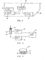
- Fig. 1 a block diagram illustrating the most important functions which are performed in a recorder according to the invention based on System I;
- Fig. 2 a ring with information being applied therein;
- Fig. 3 a block diagram illustrating the most important functions which are performed in a recorder according to the invention based upon system II.
- Fig. 5 a ring with information as used therein; and
- Fig. 6 a block diagram of a calculator module which can be used in the present pigeon recorder.
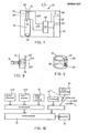
- Fig. 7 a circuitry, in which schematically the most important components of the electronic recorder according to the invention are illustrated;
- Fig. 8 a detail of the recorder, when a capacitor as loose circuit component is applied; and
- Fig. 9 a pigeon-identification-ring, modified in conformity with the invention.
- Fig.10 a block diagram of an electronic pigeon recorder according to the invention;
- Fig.11 a race-ring with a readable code;
- Fig.12 the race-ring with the vane in plan view;
- Fig.13 the same race-ring at larger scale having between the opposite faces of the vane a magnetic core;
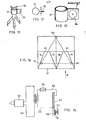
- Fig.14 a landing-platform on which a number of photocells are provided;
- Fig.15 a circuitry diagram of a magnetic loop arranged at the landing-platform, said loop cooperating with a secondary loop, as soon as the pigeon is settling itself on the landing-platform;
- Fig.16 a pigeon-house or -loft, in a perspective view, with landing-platform and two entry-gates;
- Fig.17 the landing-platform in a side-view;
- Fig.18 the landing-platform in a plan-view;
- Fig.19 a flat ring to be used in the above mentioned device;
- Fig.20 an electro-magnet;
- Fig.21 a race-set for a competitive pigeon being in comparison with that of fig. 7, much simpler;
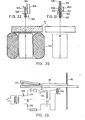
- Fig.22 a similar race-set as fig.20, the difference being that the code-carrier is not held magnetically, but mecanically;
- Fig.23 a circuit for a device with electro-magnet, which can be energized by the pigeon itself on its arrival, and
- Figures 24-26 an other device and circuit diagram of a self- activatable recorder.
- In the system I represented in Fig. 1 and 2 a pigeon taking part of a competition gets - as usual - a rubber race-
ring 1 shoven over thefoot 1 on which thecompetition number 2 is mentioned. This ring is provided circumferentially with a magneticsusceptible zone 3. After the entrance of the pigeon the ring is taken from its foot and put on arotatable ring holder 4 of the recorder. This ringholder is turned till it is automatically held in a certain position by a stop or the like. Thering 1 with itsholder 4 passes at first amagnetic wiping head 6 for wiping off any undesired magnetizing of thezone 3 picked up during the flight. Next the ring on theholder 4 is turned along a writing or signalling head 7. Due to this location of the ring on theholder 4, heretofore mentioned, aninternal clock 8 receives a signal to give a time signalling to the writing head or signalling head 7, which passes on said time information to themagnetizable zone 3 on thering 1. In the end thering 1 contains thecompetition number 2 and the time observation 3', fig. 2. - When the competition is finished, all pigeon-fanciers hand in their sealed recorder to the committee or the race-commissioner, who puts the
ring 1 in a computer-processor. Herein is also a memory, in which other competition-data are stored. After a short while the order of entrance of the pigeons is known and the average velocity has been calculated. - In fig. 3 is shown a ring which has been worked in a special manner, and which remains permanently around the pigeon's foot. The special working which the ring has undegone, is the provision of a magnetically
susceptible zone 12. If there is sufficient space on the identification ring, the latter can be provided with such azone 1, and otherwise the pigeon would receive a second ring, its width being chosen such that a magnetically susceptible zone can be provided thereon. On this zone the race-commissioner puts a competition number in magnetic code just before wickering ofthepigeons. - In System II shown in Fig. 4 and 5 optical encoding is used. On a
permanent ring 23 the pigeon's identification number is applied in barcode on anarea 24. This registration remains permanently on the ring. Next to it is azone 26, where room is available for applying the competition number in barcode. This latter however, must, with each competition, be be renewed and must not applied permanently but temporarily. To this end the barcode is adhered as self-adhesive tape orstrip 27 on thezone 26 by the race-commissioner. Before the pigeons are wickered, a reading pencil, communicating with a computer in the club's room, is passed over the two zones so that a coupling is made between the pigeon's identification number and the competition number, and it is this coupled information that is stored in the memory of the central computer. - When the pigeon has entered, the pigeon-fancier takes the
barcode strip 27 off thefoot ring 23 and sticks it to aninformation carrier 28, on which there is also a magneticsusceptible zone 29. When theinformation carrier 28 is put into the recorder, it passes anoptical eye 31, which is then caused to transmit a signal to aninternal clock 32, which passes on a time signal to a writinghead 33, that next, fixes the time observation in a magnetic code on the magneticsusceptible zone 29 of theinformation carrier 28. After-the competition these information carriers are removed by the race-commissioner from the unsealed recorder and put in the central been computer. When this has done for all participating recorders, the calcu lation work can be done by the computer. - Pigeon-fanciers who cannot wait for the calculation result of the computer which is done after the competition, can use their own pocket or table mini-computer or still simpler: connect a
calculator module 26 on the recorder module 34. The calculator module includes, according to the block diagram of fig. 6, anyway aninput 37, over which significant data are stored in amemory 38, for example the starting or releasing time, distance etc., and further thecalculation unit 39 proper and adisplay 41. Thecalculator unit 39 is connected to the central processor 16 of the recorder module 14. Thecalculator unit 39 also receives the data stored in thememory 38. The information calculated from these two kinds of data is supplied back to thememory 38 on the one hand, and on the other hand supplied to the display 14, viz. screen or registration strip. - In fig. 7 is shown very schematically an illustration of a
recorder 41 according to the invention which has in practice more or less the dimensions of a pocket mini-computer. Within thehousing 42 are accommodated : - - a
power pack 43 in the form of one or more batteries for supplying electric current to an electric current circuit 44, - - an
amplifier 6; - - a
registration device 47 for registering the time, for example; - - a
display 48 in the form of a screen. - For receiving a loose circuit-
component 49, the device includes further an entry-opening 51 in the wall of thehousing 42 to be closed by a valve 25. Below said opening there is an entry-room 53, in which the circuit element - in the case as represented a print-resistor 49 - can be contacted with thecurrent wires valve 54 in the bottom of the entry-room 53. However, in the activated position said relay opens saidvalve 54 after a certain retardation time, so that the circuit-component 49 falls into acollecting room 56 lying uhder the entry-room 53. This latter room is closed by aseal plug 57, which may be removed only by the race-commi-sioner. - In fig. 8 is drawn a detail of a recorder, as represented in fig. 1, but in a modified form. The entry-
room 53 is here made suitable for receiving a print-capacitor 59, just like theresistor 49, of small dimensions. At the side-face of the recorder - in fig. 1 at the lower side of the paper - aknob 61 is shown with which thewall 62 of the entry-room 53' can be depressed inwards a little, so that the two poles of thecapacitor 59 can contact thecontact wires - In fig. 9 a
pigeon identification ring 65 according to the invention is shown..It is to be noted that thewall 66 has locally a thickenedportion 27, provided with ahollow space 68, having suitable dimensions for receiving a print-resistor 9. In saidhollow space 68 is provided aspring 69, whereas thehollow space 28 can be closed by a closing means (not represented) for example a plug, a valve, a slide or the like. - In fig. 10 is shown an electronic pigeon recorder-according to the invention, in which the input means may be formed by a key-
board 71a or a code-reader 71b. Further this pigeon recorder comprises aclockwork 72, aprocessor 73, amemory 76 and a display orsimilar device 77. The pigeon recorder can be connected via a data-link to an external host-computer 79. - In fig. 11 is illustrated a race-
ring 81, which can rather easily be applied around a pigeon'sfoot 82, whilst forming a vane 13, where there is sufficient room for a directly readable competition number or a bar code or any other suitable code. - In fig. 12 a plan view thereof is shown.
- In fig. 13 the
ring 81 of figures 11 and 12 is shown at enlarged scale, in which between the opposite faces of the vane 83 amagnetic core 86 is arranged. This core can magnetically hold an externally provided, soft-iron plate, that can act as code-carrier. Applications thereof will be discussed here below. - In fig. 14 a landing-
platform 91 is shown in plan view and in fig. 17 in perspective view. There are two entry-gates funnelshaped partitions gates - In fig. 15 a circuitry is shown consisting of two magnetically coupled circuits. The
primary circuit 121, which is fed from the mains via anadaptor 122, is built as a loop, which is mounted around the landing-platform. Theprimary circuit 121 cooperates with asecondary circuit 123, including arectifier 124, aninterruptor 126 and arelay 127 in which a soft-iron pin 128 is slidably supported. Further there is provided a magnetic core 131, which holds magnetically a soft-iron plate 132 bearing thereon a code-carrier. If thesecondary circuit 123 is coupled magnetically with theprimary circuit 121, thepin 128 will, on energizing therelay 127, attract thelower lying plate 132 and shear same from the magnetic core 131 and substantially at the same time open thecircuit 123 at the place . .of theinterruptor 126 so that thepin 128 then releases theplate 132. - The secondary circuit, in mini-form, is carried along by a competitive pigeon, said circuit being located within a ring or ferrule, in which only the
place 132 is externally visible. - When the pigeon settles itself on the landing-platform, the coupling between the two
circuits plate 132 will drop on the landing-platform and is picked up by the pigeon-fancier. He can now read the number or code and introduce same in the pigeon recorder. - In fig. 16 a pigeon-house or
loft 135 is shown in a perspective view.'The landing-platform 91 is provided with the funnel-shaped partitions 96-99, which could be seen already in Fig. 14, and which extend towards thegates permanent magnet 137 is secured onto astring 138 mounted between two standers 141-142, such that themagnet 137 can swing inwards a little. This side-view of fig. 17 and the plan view of fig. 18 clarify this construction. In this case the pigeon is equipped with a .tape 81 as shown in Fig. 13 with an external soft-iron plate 63 bearing a code-carrier. On the other hand there can be provided around the pigeon's foot 82 a plastic ring 78, having in its wall a magnetic core 16, as shown in fig.19. - When the pigeon, on its way to the entry-
gates permanent magnet 137, the latter will swing a little inwards as clearly shown in fig. 18. - On passing this
magnet 137, theplate 132 will first be kept by the twomagnets plate 132 is separated from themagnet 86 by shearing and keeps sticking to themagnet 137. There, it can be taken from by the pigeon-fancier, whereafter the code present thereon, can be supplied to the pigeon recorder. This code can be on a sticker, acting as code-carrier, and is stuck onto theplate 132. - In the figures 20-23 a system is shown, in which the
plate 132 is released and drops onto the landing platform, as soon as the pigeon comes within the influence sphere of a strongpermanent magnet 153, .being arranged under the landing-platform 91 (fig. 20). - In fig. 21 the race-set of a competitive pigeon is shown, which set it carries along, comprising a soft-
iron plate 132, being magnetically held by one or more magnetic cores 16. Further there is provided a pin 128', differing fro thepin 128 of fig. 16 in that it is composed of several parts, viz. a soft-iron piece 156, an a-magnetic, for example plastics,part 157, a permanentmagnetic part 158 and ana-magnetic part 159. The pin as a whole rests in a ferrule 161 whereas on the bottom abias spring 162 is located. When the pigeon with this race-set walks over the landing-platform 91 and approaches the electro-magnet 153, the pin 128' is all of a sudden drawn'downwards, because the soft-iron pin 156 is in the influence sphere of themagnet 153. By this sudden pull, theplate 132 sticking to thepermanent magnet 158 is shifted off the permanentmagnetic core 86a, so far, that theplate 132 is brought beyond the attraction sphere of themagnet 86. In his turn it comes in the attraction sphere of the big electro-magnet 153 and is therefore shifted from themagnet 158. Theplate 132 falls thus on theplatform 91. At the same time the electro-magnet 158 is de-energized. - In fig. 22 a mecanical embodiment is shown. When here the soft-iron pin comes into the influence sphere of the strong electro-
magnet 153, thepin 128 will be withdrawn completely out of theopening 163 in theeyelet 164 on the code-carrier, so that the latter falls.on theplatform 91. - In fig. 23 is shown a complete circuitry of a pigeon self-service device. In the landing-platform 91' a starting switch 171 (microswitch) is arranged, which when a pigeon is settling thereon, closes a circuit by means of a hold-
relay 174. The energizing of therelay 174 closes - thecircuit 176 atinterruptor 177, in which circuit is included the strong electro-magnet 153. Thus, after the pigeon has actuated the circuitry, theplate 132 or the code-carrier 166 will be drawn out of the pigeon's race-set further-on,somewhere above the electro-magnet 153. To reset the installation again in a non-active condition, the pigeon-fancier has to actuate the key 178, causing the circuitry to return to the starting position. - The landing-
platform 91" in fig. 24 is disposed in an elastically rotatory position and provided with a micro-switch 181 (fig.26). When a pigeon lands on the platform, said micro-switch makes contact. The input of the controlling unit rises from 0 Volt to x Volt. The voltage increase (AV) acts as signal, which starts the delay-unit 184 and the flip-flop 186 of the alarm. The delay-unit 184 energize themagnet 191 during a certain time. Thealarm 187 rings until it is stopped via a reset-key. The alarm may not frighten the pigeon. The alarm goes up for example in house, so that the pigeon-fancier's attention is drawn to the pigeon's arrival. - After de-energizing of the
magnet 191 an automatic collecting and registeringmecanism 194 can be activated which can indeed energize automatically the recorder. The quick landing of a next pigeon, before the magnet is de-energized, places thecounter 184 at the begin of the delay-period.
Claims (36)
Applications Claiming Priority (6)
| Application Number | Priority Date | Filing Date | Title |
|---|---|---|---|
| NL8102046A NL8102046A (en) | 1981-04-24 | 1981-04-24 | Electronic pigeon race recorder - has sealed container for collecting data carrier bearing competition number and upon which time information is recorded |
| NL8102046 | 1981-04-24 | ||
| NL8105490A NL8105490A (en) | 1981-12-07 | 1981-12-07 | Electronic pigeon race recorder - has sealed container for collecting data carrier bearing competition number and upon which time information is recorded |
| NL8105490 | 1981-12-07 | ||
| NL8200835A NL8200835A (en) | 1982-03-02 | 1982-03-02 | Electronic pigeon race recorder - has sealed container for collecting data carrier bearing competition number and upon which time information is recorded |
| NL8200835 | 1982-03-02 |
Publications (3)
| Publication Number | Publication Date |
|---|---|
| EP0064787A2 true EP0064787A2 (en) | 1982-11-17 |
| EP0064787A3 EP0064787A3 (en) | 1983-08-03 |
| EP0064787B1 EP0064787B1 (en) | 1986-03-19 |
Family
ID=27352078
Family Applications (1)
| Application Number | Title | Priority Date | Filing Date |
|---|---|---|---|
| EP82200491A Expired EP0064787B1 (en) | 1981-04-24 | 1982-04-23 | Methods for timing pigeon races |
Country Status (2)
| Country | Link |
|---|---|
| EP (1) | EP0064787B1 (en) |
| DE (1) | DE3269936D1 (en) |
Cited By (18)
| Publication number | Priority date | Publication date | Assignee | Title |
|---|---|---|---|---|
| EP0083457A1 (en) * | 1982-01-05 | 1983-07-13 | DESCHEEMAECKER, Frans | Device for establishing the time of arrival of pigeons |
| EP0118141A2 (en) * | 1983-01-29 | 1984-09-12 | Johannes De Oude | Competition ring for pigeons and apparatus for ringing pigeons with said ring |
| DE3632958A1 (en) * | 1986-09-27 | 1987-11-12 | Heimes Horst Peter Dr Ing | Electronically recordable and readable identification ring, particularly for carrier pigeons |
| DE3801004A1 (en) * | 1988-01-15 | 1989-07-27 | Benzing Tech Uhren Gmbh | Carrier-pigeon clock |
| EP0432801A2 (en) * | 1989-12-15 | 1991-06-19 | Kazuo Takahashi | Method for determining sequence of arrival and racing time of runners at finish line by use of bar codes |
| EP0487810A1 (en) * | 1990-11-28 | 1992-06-03 | Frans De Scheemaecker | Method for checking the arrival of a pigeon and identification element and data processing unit to be used therewith |
| EP0544277A2 (en) * | 1991-11-27 | 1993-06-02 | DIEHL GMBH & CO. | Time-keeping apparatus for sporting events |
| EP0582138A2 (en) * | 1992-08-01 | 1994-02-09 | DIEHL GMBH & CO. | Device for detecting real time information |
| EP0660272A2 (en) * | 1993-12-22 | 1995-06-28 | DIEHL GMBH & CO. | Time-keeping device for sporting events |
| EP0660273A2 (en) * | 1993-12-22 | 1995-06-28 | DIEHL GMBH & CO. | Time-keeping device for sporting events |
| EP0660271A2 (en) * | 1993-12-22 | 1995-06-28 | DIEHL GMBH & CO. | Event registration device, especially for homing pigeon sport |
| GB2295926A (en) * | 1994-12-10 | 1996-06-12 | Benzing Tech Uhren Gmbh | Detection antenna |
| GB2298118A (en) * | 1995-02-27 | 1996-08-28 | Benzing Tech Uhren Gmbh | Pigeon ring |
| DE19733479A1 (en) * | 1997-08-01 | 1999-02-04 | Diehl Ident Gmbh | Pigeon leg ring |
| EP0919958A2 (en) * | 1997-11-27 | 1999-06-02 | Anatoli Stobbe | Electronic ring for competition pigeon |
| US20090181739A1 (en) * | 2008-01-10 | 2009-07-16 | Jin-Hao Chao Cheng | Competition cheat-preventing system and method |
| US20120179417A1 (en) * | 2001-12-03 | 2012-07-12 | Fernando Vincenzini | System and process for charting and displaying the time and position of contestants in a race |
| CN107316352A (en) * | 2017-07-13 | 2017-11-03 | 东莞市异能无人机科技有限公司 | A kind of unmanned plane match timing and scoring system |
Citations (21)
| Publication number | Priority date | Publication date | Assignee | Title |
|---|---|---|---|---|
| BE554970A (en) * | ||||
| US2343679A (en) * | 1942-10-27 | 1944-03-07 | Celluplastic Corp | Message holder for use with homing pigeons |
| NL6413783A (en) * | 1963-11-28 | 1965-05-31 | ||
| US3237058A (en) * | 1960-08-25 | 1966-02-22 | Bell Telephone Labor Inc | Impedance measuring circuit |
| NL6807483A (en) * | 1967-05-25 | 1968-11-26 | ||
| FR1564874A (en) * | 1968-03-13 | 1969-04-25 | ||
| DE2124562A1 (en) * | 1971-05-18 | 1972-11-30 | Hermann, Klaus Dieter, 6932 Hirschhorn | Method and device for providing labels with an adhesive layer that can be activated by heating |
| DE2245529A1 (en) * | 1971-09-20 | 1973-03-22 | Manuel Alexandre Vincen Araujo | AUTOMATIC DEVICE FOR MEASURING THE TIME REQUIRED TO CROSS A TRACK AND CONTROLLING ACCESS TO THE TRACK |
| US3894215A (en) * | 1973-10-17 | 1975-07-08 | Decicom Systems Inc | Time clock system |
| US3897753A (en) * | 1974-01-31 | 1975-08-05 | Barry Thomas Lee | Means and method for selectively controlling animals |
| FR2258787A1 (en) * | 1974-01-24 | 1975-08-22 | Kiestra Philippus | |
| GB1413377A (en) * | 1973-01-26 | 1975-11-12 | Univ Southampton | Contact lenses and magnetic means for their introduction and removal |
| US3952438A (en) * | 1971-07-06 | 1976-04-27 | Herman Miller, Inc. | Animal marking apparatus |
| DE2502108A1 (en) * | 1975-01-20 | 1976-07-22 | Sato Kenkyusho Setagaya Kk | Portable labelling machine - has removable inking cartridge fitted with roller which is spring-loaded against printing drum |
| US4011434A (en) * | 1975-08-25 | 1977-03-08 | North Electric Company | Stand-alone cumulative elapsed-time calculating system |
| FR2327586A1 (en) * | 1975-10-06 | 1977-05-06 | Cincinnati Milacron Inc | CONTROL UNIT FOR A MAGNETIC CLAMPING DEVICE OF A PART |
| US4065753A (en) * | 1974-09-09 | 1977-12-27 | Minnesota Mining & Manufacturing Company | Electromagnetically responsive projectile and system for detecting same |
| US4086453A (en) * | 1976-10-20 | 1978-04-25 | Bresan Joseph R | Game tracking device |
| LU79476A1 (en) * | 1978-04-20 | 1978-09-29 | Nedap Nv | DETECTING PLATES FOR AN IDENTIFICATION SYSTEM |
| DE2746735A1 (en) * | 1977-10-18 | 1979-04-19 | Roland Dr Ing Luecke | Time period recording device - has timer and printing mechanism reproducing clock time, date and similar information |
| US4268744A (en) * | 1979-12-05 | 1981-05-19 | Mcgeary Thomas C | Score processing system for use with ID cards |
-
1982
- 1982-04-23 EP EP82200491A patent/EP0064787B1/en not_active Expired
- 1982-04-23 DE DE8282200491T patent/DE3269936D1/en not_active Expired
Patent Citations (21)
| Publication number | Priority date | Publication date | Assignee | Title |
|---|---|---|---|---|
| BE554970A (en) * | ||||
| US2343679A (en) * | 1942-10-27 | 1944-03-07 | Celluplastic Corp | Message holder for use with homing pigeons |
| US3237058A (en) * | 1960-08-25 | 1966-02-22 | Bell Telephone Labor Inc | Impedance measuring circuit |
| NL6413783A (en) * | 1963-11-28 | 1965-05-31 | ||
| NL6807483A (en) * | 1967-05-25 | 1968-11-26 | ||
| FR1564874A (en) * | 1968-03-13 | 1969-04-25 | ||
| DE2124562A1 (en) * | 1971-05-18 | 1972-11-30 | Hermann, Klaus Dieter, 6932 Hirschhorn | Method and device for providing labels with an adhesive layer that can be activated by heating |
| US3952438A (en) * | 1971-07-06 | 1976-04-27 | Herman Miller, Inc. | Animal marking apparatus |
| DE2245529A1 (en) * | 1971-09-20 | 1973-03-22 | Manuel Alexandre Vincen Araujo | AUTOMATIC DEVICE FOR MEASURING THE TIME REQUIRED TO CROSS A TRACK AND CONTROLLING ACCESS TO THE TRACK |
| GB1413377A (en) * | 1973-01-26 | 1975-11-12 | Univ Southampton | Contact lenses and magnetic means for their introduction and removal |
| US3894215A (en) * | 1973-10-17 | 1975-07-08 | Decicom Systems Inc | Time clock system |
| FR2258787A1 (en) * | 1974-01-24 | 1975-08-22 | Kiestra Philippus | |
| US3897753A (en) * | 1974-01-31 | 1975-08-05 | Barry Thomas Lee | Means and method for selectively controlling animals |
| US4065753A (en) * | 1974-09-09 | 1977-12-27 | Minnesota Mining & Manufacturing Company | Electromagnetically responsive projectile and system for detecting same |
| DE2502108A1 (en) * | 1975-01-20 | 1976-07-22 | Sato Kenkyusho Setagaya Kk | Portable labelling machine - has removable inking cartridge fitted with roller which is spring-loaded against printing drum |
| US4011434A (en) * | 1975-08-25 | 1977-03-08 | North Electric Company | Stand-alone cumulative elapsed-time calculating system |
| FR2327586A1 (en) * | 1975-10-06 | 1977-05-06 | Cincinnati Milacron Inc | CONTROL UNIT FOR A MAGNETIC CLAMPING DEVICE OF A PART |
| US4086453A (en) * | 1976-10-20 | 1978-04-25 | Bresan Joseph R | Game tracking device |
| DE2746735A1 (en) * | 1977-10-18 | 1979-04-19 | Roland Dr Ing Luecke | Time period recording device - has timer and printing mechanism reproducing clock time, date and similar information |
| LU79476A1 (en) * | 1978-04-20 | 1978-09-29 | Nedap Nv | DETECTING PLATES FOR AN IDENTIFICATION SYSTEM |
| US4268744A (en) * | 1979-12-05 | 1981-05-19 | Mcgeary Thomas C | Score processing system for use with ID cards |
Non-Patent Citations (2)
| Title |
|---|
| IBM TECHNICAL DISCLOSURE BULLETIN, vol. 14, no. 12, May 1972, NEW YORK (US) G.V.A. MALMROS: "Acces Control System", pages 3860-3861 * |
| SIEMENS-ZEITSCHRIFT, vol.46, no.7, July 1972 (DE) W. KOLZER: "Auromatisches Datenerfassungssystem bei den olympischen Schwimmwettkampfen", pages 553-556 * |
Cited By (34)
| Publication number | Priority date | Publication date | Assignee | Title |
|---|---|---|---|---|
| EP0083457A1 (en) * | 1982-01-05 | 1983-07-13 | DESCHEEMAECKER, Frans | Device for establishing the time of arrival of pigeons |
| EP0118141A2 (en) * | 1983-01-29 | 1984-09-12 | Johannes De Oude | Competition ring for pigeons and apparatus for ringing pigeons with said ring |
| EP0118141A3 (en) * | 1983-01-29 | 1984-12-19 | Johannes De Oude | Apparatus for providing pigeons with rings for competition flights |
| DE3632958A1 (en) * | 1986-09-27 | 1987-11-12 | Heimes Horst Peter Dr Ing | Electronically recordable and readable identification ring, particularly for carrier pigeons |
| DE3801004A1 (en) * | 1988-01-15 | 1989-07-27 | Benzing Tech Uhren Gmbh | Carrier-pigeon clock |
| DE3801004C2 (en) * | 1988-01-15 | 1999-01-07 | Benzing Tech Uhren Gmbh | Carrier pigeon clock |
| EP0432801A3 (en) * | 1989-12-15 | 1992-05-06 | Kazuo Takahashi | Method for determining sequence of arrival and racing time of runners at finish line by use of bar codes |
| EP0432801A2 (en) * | 1989-12-15 | 1991-06-19 | Kazuo Takahashi | Method for determining sequence of arrival and racing time of runners at finish line by use of bar codes |
| EP0487810A1 (en) * | 1990-11-28 | 1992-06-03 | Frans De Scheemaecker | Method for checking the arrival of a pigeon and identification element and data processing unit to be used therewith |
| EP0544277A2 (en) * | 1991-11-27 | 1993-06-02 | DIEHL GMBH & CO. | Time-keeping apparatus for sporting events |
| EP0544277A3 (en) * | 1991-11-27 | 1995-05-24 | Diehl Gmbh & Co | Time-keeping apparatus for sporting events |
| EP0582138A2 (en) * | 1992-08-01 | 1994-02-09 | DIEHL GMBH & CO. | Device for detecting real time information |
| EP0582138A3 (en) * | 1992-08-01 | 1995-05-24 | Diehl Gmbh & Co | Device for detecting real time information. |
| EP0660273A3 (en) * | 1993-12-22 | 1996-05-22 | Diehl Gmbh & Co | Time-keeping device for sporting events. |
| EP0660271A3 (en) * | 1993-12-22 | 1996-02-21 | Diehl Gmbh & Co | Event registration device, especially for homing pigeon sport. |
| EP0660273A2 (en) * | 1993-12-22 | 1995-06-28 | DIEHL GMBH & CO. | Time-keeping device for sporting events |
| EP0660272A3 (en) * | 1993-12-22 | 1996-05-22 | Diehl Gmbh & Co | Time-keeping device for sporting events. |
| US5654685A (en) * | 1993-12-22 | 1997-08-05 | Diehl Gmbh & Co. | Timekeeping arrangement for sporting competitions |
| AU683959B2 (en) * | 1993-12-22 | 1997-11-27 | Diehl Stiftung & Co. | Timekeeping arrangement for sporting competitions |
| EP0660272A2 (en) * | 1993-12-22 | 1995-06-28 | DIEHL GMBH & CO. | Time-keeping device for sporting events |
| EP0660271A2 (en) * | 1993-12-22 | 1995-06-28 | DIEHL GMBH & CO. | Event registration device, especially for homing pigeon sport |
| GB2295926A (en) * | 1994-12-10 | 1996-06-12 | Benzing Tech Uhren Gmbh | Detection antenna |
| GB2295926B (en) * | 1994-12-10 | 1997-12-03 | Benzing Tech Uhren Gmbh | Antenna |
| GB2298118B (en) * | 1995-02-27 | 1999-04-28 | Benzing Tech Uhren Gmbh | A process for ringing a carrier pigeon and carrier pigeon ring for use therein |
| GB2298118A (en) * | 1995-02-27 | 1996-08-28 | Benzing Tech Uhren Gmbh | Pigeon ring |
| DE19733479A1 (en) * | 1997-08-01 | 1999-02-04 | Diehl Ident Gmbh | Pigeon leg ring |
| BE1013069A3 (en) * | 1997-08-01 | 2001-09-04 | Aeg Identifikationssys Gmbh | METHOD AND MECHANISM FOR REGISTRATION IN THE TIMES pigeon sport. |
| EP0919958A2 (en) * | 1997-11-27 | 1999-06-02 | Anatoli Stobbe | Electronic ring for competition pigeon |
| EP0919958A3 (en) * | 1997-11-27 | 2000-04-12 | Anatoli Stobbe | Electronic ring for competition pigeon |
| US20120179417A1 (en) * | 2001-12-03 | 2012-07-12 | Fernando Vincenzini | System and process for charting and displaying the time and position of contestants in a race |
| US20090181739A1 (en) * | 2008-01-10 | 2009-07-16 | Jin-Hao Chao Cheng | Competition cheat-preventing system and method |
| US8128470B2 (en) * | 2008-01-10 | 2012-03-06 | Jin-Hao Chao Cheng | Competition cheat-preventing system and method |
| CN107316352A (en) * | 2017-07-13 | 2017-11-03 | 东莞市异能无人机科技有限公司 | A kind of unmanned plane match timing and scoring system |
| CN107316352B (en) * | 2017-07-13 | 2023-03-28 | 东莞市异能无人机科技有限公司 | Unmanned aerial vehicle match timing branch system |
Also Published As
| Publication number | Publication date |
|---|---|
| EP0064787B1 (en) | 1986-03-19 |
| DE3269936D1 (en) | 1986-04-24 |
| EP0064787A3 (en) | 1983-08-03 |
Similar Documents
| Publication | Publication Date | Title |
|---|---|---|
| EP0064787A2 (en) | Methods for timing pigeon races | |
| US5525969A (en) | Monitoring device for location verification | |
| US4609780A (en) | Electronic secure entry system, apparatus and method | |
| US4086475A (en) | Ticket taking system | |
| JPH02501600A (en) | Portable manual device for automatic processing of data recorded on data supports | |
| GB2208024A (en) | Parking meters capable of being operated without monetary coins | |
| SE433014B (en) | PARKING FACILITIES, PREFERRED TO CYCLES | |
| US3548161A (en) | Vehicle parking time and fee computing system | |
| US2278357A (en) | Identification apparatus | |
| US20090236804A1 (en) | Playing Cards with Electronic Circuitry | |
| JPS6162816A (en) | Device for gaining, recording and evaluating inspection-process data | |
| JP5849080B2 (en) | Amusement hall apparatus and amusement hall system including the amusement hall apparatus | |
| US3281855A (en) | Apparatus for monitoring the operation of a machine | |
| JP6062023B2 (en) | Amusement machine equipment | |
| EP0783161A3 (en) | Double registration control of entry and exit of persons or things in a predetermined zone | |
| JP3819227B2 (en) | Automatic determination method for lottery results | |
| US4139764A (en) | Event monitor for court games | |
| JP2014098955A (en) | Automatic reception device and reception system | |
| EP0118141A2 (en) | Competition ring for pigeons and apparatus for ringing pigeons with said ring | |
| JPS5975383A (en) | Electric memory for dove racing | |
| JPH11183194A (en) | Noncontact information management system | |
| JP2007143738A (en) | Game medium counting system, game medium counting device, managing unit and game medium counting method | |
| JPH07246265A (en) | Timer for sports competition | |
| NL8102046A (en) | Electronic pigeon race recorder - has sealed container for collecting data carrier bearing competition number and upon which time information is recorded | |
| JPS599329Y2 (en) | Ski lift common use ticket processing device |
Legal Events
| Date | Code | Title | Description |
|---|---|---|---|
| PUAI | Public reference made under article 153(3) epc to a published international application that has entered the european phase |
Free format text: ORIGINAL CODE: 0009012 |
|
| AK | Designated contracting states |
Designated state(s): BE DE FR GB NL |
|
| RBV | Designated contracting states (corrected) |
Designated state(s): BE DE FR GB NL |
|
| PUAL | Search report despatched |
Free format text: ORIGINAL CODE: 0009013 |
|
| AK | Designated contracting states |
Designated state(s): BE DE FR GB NL |
|
| 17P | Request for examination filed |
Effective date: 19840203 |
|
| GRAA | (expected) grant |
Free format text: ORIGINAL CODE: 0009210 |
|
| AK | Designated contracting states |
Kind code of ref document: B1 Designated state(s): BE DE FR GB NL |
|
| REF | Corresponds to: |
Ref document number: 3269936 Country of ref document: DE Date of ref document: 19860424 |
|
| ET | Fr: translation filed | ||
| PLBE | No opposition filed within time limit |
Free format text: ORIGINAL CODE: 0009261 |
|
| STAA | Information on the status of an ep patent application or granted ep patent |
Free format text: STATUS: NO OPPOSITION FILED WITHIN TIME LIMIT |
|
| 26N | No opposition filed | ||
| PGFP | Annual fee paid to national office [announced via postgrant information from national office to epo] |
Ref country code: FR Payment date: 19980429 Year of fee payment: 17 |
|
| PGFP | Annual fee paid to national office [announced via postgrant information from national office to epo] |
Ref country code: NL Payment date: 19980430 Year of fee payment: 17 |
|
| PGFP | Annual fee paid to national office [announced via postgrant information from national office to epo] |
Ref country code: GB Payment date: 19980504 Year of fee payment: 17 |
|
| PGFP | Annual fee paid to national office [announced via postgrant information from national office to epo] |
Ref country code: BE Payment date: 19980506 Year of fee payment: 17 |
|
| PGFP | Annual fee paid to national office [announced via postgrant information from national office to epo] |
Ref country code: DE Payment date: 19980529 Year of fee payment: 17 |
|
| PG25 | Lapsed in a contracting state [announced via postgrant information from national office to epo] |
Ref country code: GB Free format text: LAPSE BECAUSE OF NON-PAYMENT OF DUE FEES Effective date: 19990423 |
|
| PG25 | Lapsed in a contracting state [announced via postgrant information from national office to epo] |
Ref country code: BE Free format text: LAPSE BECAUSE OF NON-PAYMENT OF DUE FEES Effective date: 19990430 |
|
| BERE | Be: lapsed |
Owner name: DE OUDE JOHANNES Effective date: 19990430 |
|
| PG25 | Lapsed in a contracting state [announced via postgrant information from national office to epo] |
Ref country code: NL Free format text: LAPSE BECAUSE OF NON-PAYMENT OF DUE FEES Effective date: 19991101 |
|
| GBPC | Gb: european patent ceased through non-payment of renewal fee |
Effective date: 19990423 |
|
| PG25 | Lapsed in a contracting state [announced via postgrant information from national office to epo] |
Ref country code: FR Free format text: LAPSE BECAUSE OF NON-PAYMENT OF DUE FEES Effective date: 19991231 |
|
| NLV4 | Nl: lapsed or anulled due to non-payment of the annual fee |
Effective date: 19991101 |
|
| REG | Reference to a national code |
Ref country code: FR Ref legal event code: ST |
|
| PG25 | Lapsed in a contracting state [announced via postgrant information from national office to epo] |
Ref country code: DE Free format text: LAPSE BECAUSE OF NON-PAYMENT OF DUE FEES Effective date: 20000201 |