EP0065541B1 - Intraocular lens forceps - Google Patents
Intraocular lens forceps Download PDFInfo
- Publication number
- EP0065541B1 EP0065541B1 EP19810903186 EP81903186A EP0065541B1 EP 0065541 B1 EP0065541 B1 EP 0065541B1 EP 19810903186 EP19810903186 EP 19810903186 EP 81903186 A EP81903186 A EP 81903186A EP 0065541 B1 EP0065541 B1 EP 0065541B1
- Authority
- EP
- European Patent Office
- Prior art keywords
- lens
- jaw members
- fulcrum
- extensions
- combination
- Prior art date
- Legal status (The legal status is an assumption and is not a legal conclusion. Google has not performed a legal analysis and makes no representation as to the accuracy of the status listed.)
- Expired
Links
Images
Classifications
-
- A—HUMAN NECESSITIES
- A61—MEDICAL OR VETERINARY SCIENCE; HYGIENE
- A61F—FILTERS IMPLANTABLE INTO BLOOD VESSELS; PROSTHESES; DEVICES PROVIDING PATENCY TO, OR PREVENTING COLLAPSING OF, TUBULAR STRUCTURES OF THE BODY, e.g. STENTS; ORTHOPAEDIC, NURSING OR CONTRACEPTIVE DEVICES; FOMENTATION; TREATMENT OR PROTECTION OF EYES OR EARS; BANDAGES, DRESSINGS OR ABSORBENT PADS; FIRST-AID KITS
- A61F2/00—Filters implantable into blood vessels; Prostheses, i.e. artificial substitutes or replacements for parts of the body; Appliances for connecting them with the body; Devices providing patency to, or preventing collapsing of, tubular structures of the body, e.g. stents
- A61F2/02—Prostheses implantable into the body
- A61F2/14—Eye parts, e.g. lenses, corneal implants; Implanting instruments specially adapted therefor; Artificial eyes
- A61F2/16—Intraocular lenses
- A61F2/1662—Instruments for inserting intraocular lenses into the eye
-
- A—HUMAN NECESSITIES
- A61—MEDICAL OR VETERINARY SCIENCE; HYGIENE
- A61B—DIAGNOSIS; SURGERY; IDENTIFICATION
- A61B17/00—Surgical instruments, devices or methods, e.g. tourniquets
- A61B17/30—Surgical pincettes without pivotal connections
Definitions
- the condition of lenticular opacity in the eye is a leading cause of blindness and is especially common among the elderly.
- the primary means of alleviating a cataract is to remove the diseased natural lens, and more than 400,000 persons in the United States undergo surgery for removal of clouded lenses in eyes each year.
- the eye When no lens is present in the eye, which is known as an aphakic condition or aphakia and is usually the result of intracapsular or extra- capsular lens extraction, the eye does not have the ability to focus rays of light. Therefore, the eye receives a blurred image and vision is severely impaired.
- the most common solution for providing a focusing mechanism to obviate the aphakic condition is to interpose contact lenses or spectacles or a combination thereof between the eye and the light entering therein.
- both contact lenses and spectacles have drawbacks when used in the treatment of aphakia.
- Neither spectacles nor contact lenses can duplicate the natural optical system because they are positioned outside of the eye, which results in a shift of the optical center from the vivo state. Because the optical center has been shifted, the image received by the eye is changed in size.
- Contact lenses are superior to thick cataract spectacles since the wearer enjoys good peripheral vision.
- the magnification problem does not bother contact lens wearers as much as it does cataract spectacle wearers, because the contact lenses only magnify in the range of 7 to 10 percent.
- hand to eye coordination of contact lens wearers is better than in spectacle wearers, as objects are seen in more normal spatial orientation and straight lines are not seen as curves.
- contact lenses are very small and fragile, and it is difficult to insert and remove them daily, particularly for elderly users or individuals with arthritis or coordination problems. In addition allergies and dry eye conditions also interfere with contact lens wearing.
- An intraocular lens (hereinafter sometimes referred to as an IOL in various parts of the specification) is one which is placed inside the eye.
- an IOL is implanted in substantially the same location formerly occupied by the natural lens, relatively normal vision may be restored to the patient.
- lens implantation and cataract surgery takes around 45 minutes to an hour and with the lens implant the person usually has improved vision within a couple of days, and continued improvement over several more weeks until the eye is completely healed.
- Intraocular lenses provide a significant improvement over the previously used artificial ocular aids in that once the implantation has been implemented patients regain a close approximation of their former visual function.
- the wearers of intraocular lens implants regain full side to side vision and problems of magnification and depth perception are practically non-existent. Since the intraocular lenses are permanently implanted within the eye, problems of daily cleaning, insertion and removal, and loss and replacement are eliminated. Furthermore, the wearer can enjoy sports such as swimming as the lenses remain in the eye and cosmetically there is no difference between persons who have intraocular lenses and those persons who have had no history of cataracts or eye surgery.
- lenses which are placed in the anterior chamber and are secured to the iris by various methods are shown in United States Patent Nos. 3,673,611; 3,906,551; 3,922,728; 3,925,825; 3,971,073; 3,975,779; 3,979,780; 3,986,214; 3,996,627; 4,010,496; 4,056,855; 4,073,015; 4,077,071; 4,079,470; and 4,087,866.
- U.S. Patent No. 3,913,148 discloses a lens apparatus inserted in the posterior chamber, with a plurality of cantilevered clips, each of which is mounted to a central portion which extends outward from the face of the lens towards the periphery.
- the clips are used to secure the iris to the front face of the lens when the lens is positioned within the posterior chamber of the eye behind the iris.
- each intraocular lens is less than half the diameter of a contact lens and is correspondingly light and flimsier.
- an intraocular lens may be subject to scratching of its surface which degrades its optical qualities, but unlike exterior lenses, the intraocular lens is not easily replaced when damaged.
- lens holder for contact lenses in the prior art is found in United States Patent No. 3,063,083 and corresponding GB-A-999138.
- the lens holder is used for immersing a contact lens in cleaning fluid.
- the jaws of the lens holder are lined with radial protuberances arranged in pairs spaced intermittently about the edges of the lens within the jaws. The circumference of the lens is engaged by the protuberances so that the periphery of the lens is separated from the jaws by clearance spaces.
- the minimal contact of the lens holder with the lens allows the greatest amount of lens surface area to come into contact with the cleaning fluid.
- United States Patent No. 3,817,087 discloses a wound clip removal device with jaws biased in a partly open positioned. The jaws may be opened further by placing pressure on two bowed handle portions which flex the jaws open.
- the holding means should maintain a constant grasp on the lens during manipulation by the physician, because small differences in tension and motion may result in dropping the lens onto an unsterile surface or a surface which scratches the lens or even losing grasp of the lens at a critical moment of implantation.
- Ordinary forceps have the disadvantage of requiring finger pressure to hold the lens, and movement of the jaws is magnified as compared to the movement of the compressing fingers.
- the lens holder should also be strong, light and of small dimensions so that it is easy to manipulate yet not so large as to require broad incision into the eye.
- an intraocular lens having a predetermined diameter and a lens holder therefor said lens holder comprising first and second jaw members, a fulcrum, and a handle; each of said first and second jaw members being attached to said fulcrum and spaced apart from one another, said jaw members being arranged so as to selectively hold and release the lens, said handle comprising first and second extensions of said first and second jaw members beyond said fulcrum, said extensions being substantially identical to each other and spaced apart from one another for a predetermined distance from said fulcrum, said extensions being united at a distance from said fulcrum, each of said first and second jaw members defining an inner face, said inner faces being spaced apart a distance less than said diameter of said lens, each of said jaw members further defining an arcuate slot within said inner face retaining said lens without applying pressure thereto, said arcuate slots preferably being of a radius equal to the radius of said lens, said first and second extensions being coupled respectively to said first and second jaw members
- the pair of jaws are spaced apart a distance slightly less than the diameter of the lens to'be held, and the surfaces of the jaws which face each other are slotted lengthwise so that when the jaws are in their normal position, a lens may be retained within the slotted faces without pressure.
- the neck of the holder is flattened in the same plane as the lens so that both may be inserted through a small surgical incision without difficulty.
- the fulcrum normally comprises a small cross piece extending between the two jaws and behind the slotted jaw surfaces in which the lens is held.
- the jaws extend beyond the fulcrum to form a handle, and the extension of the jaws eventually unite at a point well beyond the fulcrum.
- the jaws and the handle preferably meet at the fulcrum at an angle to each other to allow placement of the lens without either prying the cornea or the iris during its insertion.
- the lens When the lens is placed at the implantation site, it may be released from the jaws by squeezing the extensions of the jaws behind the fulcrum. The jaws are forced apart through the action of the fulcrum allowing removal of the holder from the surgical site, leaving the lens behind.
- the present invention may be made of one-piece disposable semi-rigid plastic or other smooth lightweight material, and has no jagged edges or surfaces to interfere with manipulation by the physician or to damage the eye or the lens itself. Being of one-piece construction, the present invention also offers the advantage of having no delicate small separable parts to lose or be dropped within or without the eye.
- the present invention will be packaged in a sterile wrapping with a lens placed in the jaws. Therefore, the physician need not expose the holder or the lens to potentially destructive sterilization procedures immediately prior to implantation.
- FIGURES 1 through 4 show the preferred embodiment and best mode of the invention.
- the lens holder generally indicated at 10, comprises a pair of opposed jaws 12, a fulcrum 14 separating the jaws 12, and an extension 18 of each of the two jaws 12 extending away from the fulcrum 14.
- the two jaw extensions 18 meet to form handle 22 at an integral connection 19.
- the extensions 18 meet at a distance from fulcrum 14 which ranges from 3.175 to 4.445 cm (1.25 to 1.75 inches) and is preferably 3.4925 cm (1.375 inches).
- the two extensions 18 are separated from each other allowing finger pressure on the jaw extensions 18 to push the jaw extensions 18 toward each other into contact with one another.
- each opposing jaw 12 defines an arcuate slot 16, the radius of which corresponds to the radius of the intraocular lens intended to be held by the jaws 12.
- a typical intraocular lens 20 may be held securely within the slots 16 of the jaws 12 without pressure on the lens 20.
- FIGURE 3 shows a cross- section of the jaws 12 and lens 20 taken at line A-A' of FIGURE 2, and shows that the portion of the jaws 12 which surround the slots 16 and the lens 20 prevents the lens 20 from moving to the right or to the left.
- the mouth 13 of jaws 12 is normally open less than the diameter of lens 20, so that lens 20 may not fall out of the mouth.
- FIGURE 1 shows the manner in which the lens 20 may be released from the jaws 12 when the lens is placed within the eye during a surgical operation.
- the jaw extensions 18 are depressed by finger pressure toward one another and may contact one another. Pressure on jaw extensions 18 rotates the jaws 12 around fulcrum 14, thus moving the slots 16 away from lens 20 and enlarging the mouth between the jaws 12 so that the diameter of lens 20 is less than the width of the mouth.
- Contact of the jaw extensions 18 against each other affords positive feedback to the surgeon that the lens has been released, and is not damaging to the lens 20 or the lens holder 10. Positive feedback of this sort is extremely valuable to a physician in surgical procedures such as intraocular lens placement where both the lens and the tissues involved are small, and the physician's ability to view the surgical site is limited.
- FIGURE 4 shows the angle at which the jaws 12 are mounted with respect to the jaw extensions 18 and handle 22.
- the placement of jaws 12 at an acute angle to the line of jaw extensions 18 and handle 22 allows the physician to manoeuver more accurately within the confines of the human eye than would a straight lens holder. This angle preferably falls within the range of ten degrees to fifty degrees.
- the angled construction allows placement of the lens without prying either the cornea or the iris during its insertion.
- the lens holder is typically formed by injection molding of a thermoplastic which is rigid or semi-rigid and sufficiently flexible to allow jaw and extension movement in the shape and size required.
- plastics include high density polyethylene, polypropylene, filled or unfilled polyacetyl, polystyrene, ABS polymers and nylon.
- the lens holder is made of fiberglass-filled polyacetyl. These materials give maximum strength with minimal volume, and allow the jaw extensions 18 to resist normal finger pressure and prevent accidental opening of the jaws. Thus, the lens holder thus gives the maximum finger control and requires sufficient force to open the jaws while being easy to manipulate with respect to rotation. Furthermore, the constructional distances of the lens holder are such that magnification of movement does not occur.
- the lens holder 10 is sterilized immediately after manufacture and then packaged in an air-tight plastic envelope wrapper with a sterilized lens 20 placed between jaws 12. This enables the physician to avoid the step of placing or grasping a lens 20 within jaws 12 of the lens holder which could allow the lens to pop out of the holder in an undesirable location or cause damage to the lens. While the preferred embodiment of the invention has been disclosed, it is understood that the invention is not limited to such an embodiment, since it may be otherwise embodied in the scope of the appended claims.
Abstract
Description
- The condition of lenticular opacity in the eye, known as a cataract, is a leading cause of blindness and is especially common among the elderly. The primary means of alleviating a cataract is to remove the diseased natural lens, and more than 400,000 persons in the United States undergo surgery for removal of clouded lenses in eyes each year.
- When no lens is present in the eye, which is known as an aphakic condition or aphakia and is usually the result of intracapsular or extra- capsular lens extraction, the eye does not have the ability to focus rays of light. Therefore, the eye receives a blurred image and vision is severely impaired.
- The most common solution for providing a focusing mechanism to obviate the aphakic condition is to interpose contact lenses or spectacles or a combination thereof between the eye and the light entering therein. However, both contact lenses and spectacles have drawbacks when used in the treatment of aphakia. Neither spectacles nor contact lenses can duplicate the natural optical system because they are positioned outside of the eye, which results in a shift of the optical center from the vivo state. Because the optical center has been shifted, the image received by the eye is changed in size.
- Many aphakia patients who have had their cataracts removed are fitted with glasses or spectacles. These thick lenses present many more problems than they solve. Immediately upon receiving cataract spectacles a patient is confronted with several problems in that there is significant increase in the size and shape of familiar objects and straight lines are formed into curves.
- Contact lenses are superior to thick cataract spectacles since the wearer enjoys good peripheral vision. The magnification problem does not bother contact lens wearers as much as it does cataract spectacle wearers, because the contact lenses only magnify in the range of 7 to 10 percent. Furthermore, hand to eye coordination of contact lens wearers is better than in spectacle wearers, as objects are seen in more normal spatial orientation and straight lines are not seen as curves. However, contact lenses are very small and fragile, and it is difficult to insert and remove them daily, particularly for elderly users or individuals with arthritis or coordination problems. In addition allergies and dry eye conditions also interfere with contact lens wearing.
- The most promising method of sight restoration for cataract patients is the intraocular lens. An intraocular lens (hereinafter sometimes referred to as an IOL in various parts of the specification) is one which is placed inside the eye. When an IOL is implanted in substantially the same location formerly occupied by the natural lens, relatively normal vision may be restored to the patient. Generally lens implantation and cataract surgery takes around 45 minutes to an hour and with the lens implant the person usually has improved vision within a couple of days, and continued improvement over several more weeks until the eye is completely healed.
- Intraocular lenses provide a significant improvement over the previously used artificial ocular aids in that once the implantation has been implemented patients regain a close approximation of their former visual function. The wearers of intraocular lens implants regain full side to side vision and problems of magnification and depth perception are practically non-existent. Since the intraocular lenses are permanently implanted within the eye, problems of daily cleaning, insertion and removal, and loss and replacement are eliminated. Furthermore, the wearer can enjoy sports such as swimming as the lenses remain in the eye and cosmetically there is no difference between persons who have intraocular lenses and those persons who have had no history of cataracts or eye surgery.
- Examples of lenses which are placed in the anterior chamber and are secured to the iris by various methods are shown in United States Patent Nos. 3,673,611; 3,906,551; 3,922,728; 3,925,825; 3,971,073; 3,975,779; 3,979,780; 3,986,214; 3,996,627; 4,010,496; 4,056,855; 4,073,015; 4,077,071; 4,079,470; and 4,087,866.
- Artificial lenses designed for positioning in the posterior chamber are described in United States Patent Nos. 3,711,870 and 4,014,049. The lenses disclosed in these patents comprise a central optical element surrounded by a resilient silicone flange shaped to receive and nest against the ciliary body. The lenses are held in place by suturing the resilient flange to the ciliary body. Another lens shown in U.S. Patent Nos. 3,925,835 and 4,014,089 is designed for implantation in either the anterior or posterior chamber of the eye, with the lens supporting (haptic) section of the IOL comprising a plurality of flexible spring like members designed to follow the margin of the dynamic pupil, while providing longitudinal fixation and centration of the lens. Patent Nos. 4,053,953 and 3,866,249 disclose a posterior lens held in place by an insertion necklace in the former and a holding ring in the latter. In U.S. Patent No. 4,041,552 the lens element is placed in the posterior chamber and supported by support on the anterior side of the iris, while a lower arm is sutured to the ciliary body and sclera at one side of the iris with another arm extending to the opposite side.
- U.S. Patent No. 3,913,148 discloses a lens apparatus inserted in the posterior chamber, with a plurality of cantilevered clips, each of which is mounted to a central portion which extends outward from the face of the lens towards the periphery. The clips are used to secure the iris to the front face of the lens when the lens is positioned within the posterior chamber of the eye behind the iris.
- Various lenses are discussed in an article by D.P. Choyce entitled "History of Intraocular Implants" which is printed in Annals of Opthal- mology, October 1973. The article also includes a list of references from which further information concerning prior art intraocular lenses can be obtained. The aforementioned prior art lenses represent typical lenses which can be used in the present lens holding apparatus.
- In the performance of intraocular lens implantation surgery, it is of course necessary to place and orient the delicate plastic lens accurately at the implantation site. Typically, each intraocular lens is less than half the diameter of a contact lens and is correspondingly light and flimsier. Like contact lenses and spectacles, an intraocular lens may be subject to scratching of its surface which degrades its optical qualities, but unlike exterior lenses, the intraocular lens is not easily replaced when damaged.
- An example of a lens holder for contact lenses in the prior art is found in United States Patent No. 3,063,083 and corresponding GB-A-999138. In these references, the lens holder is used for immersing a contact lens in cleaning fluid. The jaws of the lens holder are lined with radial protuberances arranged in pairs spaced intermittently about the edges of the lens within the jaws. The circumference of the lens is engaged by the protuberances so that the periphery of the lens is separated from the jaws by clearance spaces. Thus, the minimal contact of the lens holder with the lens allows the greatest amount of lens surface area to come into contact with the cleaning fluid. However the pressure exerted on the lens, whilst acceptable in the context of the contact lenses being dealt with, is not acceptable in holding an intraocular lens, which offers less structural resistance to damage than a contact lens. Further if a device of these two specifications scaled down to a size appropriate to an intraocular lens, the sizes of jaws would be greater than is appropriate for a minimal surgical incision length on the eye.
- United States Patent No. 3,817,087 discloses a wound clip removal device with jaws biased in a partly open positioned. The jaws may be opened further by placing pressure on two bowed handle portions which flex the jaws open.
- Other patents of interest in the field of small clamping devices include United States Patent Nos. 1,521,689; 1,748,765; 2,222,744; 2,477,466; 2,595,683; 2,943,521; 3,063,083; 3,265,068; 3,650,008; 3,677,112; 3,817,078; 3,977,410; and 4,044,771. These devices share the deficiencies of numerous sharp and abrasive surfaces and a lack of adaptation for the particular nature of intraocular lenses.
- Therefore, there is a clear need in the art for a means to hold an intraocular lens during surgery which will allow a lens to be oriented properly and accurately positioned either anterior or posterior to the iris, and which will hold the lens securely, yet without excess pressure which may damage the lens. The lenses generally have small loops which must be manoeuvered to engage them into proper position. The lens holder should firmly grasp the lens but not continuously squeeze it since pressure can induce a creep into plastic lens material which will distort the optical qualities of the lens. In addition, since there is little room in the anterior chamber to manipulate a lens, the neck of the inserting device must be kept small. Further, the holding means should maintain a constant grasp on the lens during manipulation by the physician, because small differences in tension and motion may result in dropping the lens onto an unsterile surface or a surface which scratches the lens or even losing grasp of the lens at a critical moment of implantation. Ordinary forceps have the disadvantage of requiring finger pressure to hold the lens, and movement of the jaws is magnified as compared to the movement of the compressing fingers. The lens holder should also be strong, light and of small dimensions so that it is easy to manipulate yet not so large as to require broad incision into the eye.
- According to the present invention there is provided a combination of an intraocular lens having a predetermined diameter and a lens holder therefor said lens holder comprising first and second jaw members, a fulcrum, and a handle; each of said first and second jaw members being attached to said fulcrum and spaced apart from one another, said jaw members being arranged so as to selectively hold and release the lens, said handle comprising first and second extensions of said first and second jaw members beyond said fulcrum, said extensions being substantially identical to each other and spaced apart from one another for a predetermined distance from said fulcrum, said extensions being united at a distance from said fulcrum, each of said first and second jaw members defining an inner face, said inner faces being spaced apart a distance less than said diameter of said lens, each of said jaw members further defining an arcuate slot within said inner face retaining said lens without applying pressure thereto, said arcuate slots preferably being of a radius equal to the radius of said lens, said first and second extensions being coupled respectively to said first and second jaw members and sufficiently flexible so that finger compression of said extensions together separates said jaw members to release said lens held in said holder.
- The pair of jaws are spaced apart a distance slightly less than the diameter of the lens to'be held, and the surfaces of the jaws which face each other are slotted lengthwise so that when the jaws are in their normal position, a lens may be retained within the slotted faces without pressure. The neck of the holder is flattened in the same plane as the lens so that both may be inserted through a small surgical incision without difficulty.
- The fulcrum normally comprises a small cross piece extending between the two jaws and behind the slotted jaw surfaces in which the lens is held. The jaws extend beyond the fulcrum to form a handle, and the extension of the jaws eventually unite at a point well beyond the fulcrum. The jaws and the handle preferably meet at the fulcrum at an angle to each other to allow placement of the lens without either prying the cornea or the iris during its insertion.
- When the lens is placed at the implantation site, it may be released from the jaws by squeezing the extensions of the jaws behind the fulcrum. The jaws are forced apart through the action of the fulcrum allowing removal of the holder from the surgical site, leaving the lens behind.
- The present invention may be made of one-piece disposable semi-rigid plastic or other smooth lightweight material, and has no jagged edges or surfaces to interfere with manipulation by the physician or to damage the eye or the lens itself. Being of one-piece construction, the present invention also offers the advantage of having no delicate small separable parts to lose or be dropped within or without the eye.
- Typically, the present invention will be packaged in a sterile wrapping with a lens placed in the jaws. Therefore, the physician need not expose the holder or the lens to potentially destructive sterilization procedures immediately prior to implantation.
- The above-mentioned purposes and operations of the invention are more readily apparent when read in conjunction with the following description of the drawings, and the detailed discussion of the preferred embodiment of the present invention.
-
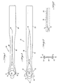
- FIGURE 1 is a top plan view of the forceps of the invention showing the jaws in an open position;
- FIGURE 2 is a top plan view of the apparatus of FIGURE 1 with the jaws shown in a closed position;
- FIGURE 3 is a cross-sectional view of the apparatus of FIGURE 2 taken along line A-A'; and
- FIGURE 4 is a side view of the apparatus of FIGURE 1.
- FIGURES 1 through 4 show the preferred embodiment and best mode of the invention. The lens holder, generally indicated at 10, comprises a pair of
opposed jaws 12, a fulcrum 14 separating thejaws 12, and anextension 18 of each of the twojaws 12 extending away from thefulcrum 14. The twojaw extensions 18 meet to formhandle 22 at anintegral connection 19. Theextensions 18 meet at a distance fromfulcrum 14 which ranges from 3.175 to 4.445 cm (1.25 to 1.75 inches) and is preferably 3.4925 cm (1.375 inches). Thus, the twoextensions 18 are separated from each other allowing finger pressure on thejaw extensions 18 to push thejaw extensions 18 toward each other into contact with one another. - The face of each opposing
jaw 12 defines anarcuate slot 16, the radius of which corresponds to the radius of the intraocular lens intended to be held by thejaws 12. When thejaws 12 are in their normal closed position as is illustrated in FIGURE 2, a typicalintraocular lens 20 may be held securely within theslots 16 of thejaws 12 without pressure on thelens 20. FIGURE 3 shows a cross- section of thejaws 12 andlens 20 taken at line A-A' of FIGURE 2, and shows that the portion of thejaws 12 which surround theslots 16 and thelens 20 prevents thelens 20 from moving to the right or to the left. Referring again to FIGURE 2, themouth 13 ofjaws 12 is normally open less than the diameter oflens 20, so thatlens 20 may not fall out of the mouth. - FIGURE 1 shows the manner in which the
lens 20 may be released from thejaws 12 when the lens is placed within the eye during a surgical operation. Thejaw extensions 18 are depressed by finger pressure toward one another and may contact one another. Pressure onjaw extensions 18 rotates thejaws 12 aroundfulcrum 14, thus moving theslots 16 away fromlens 20 and enlarging the mouth between thejaws 12 so that the diameter oflens 20 is less than the width of the mouth. Contact of thejaw extensions 18 against each other affords positive feedback to the surgeon that the lens has been released, and is not damaging to thelens 20 or thelens holder 10. Positive feedback of this sort is extremely valuable to a physician in surgical procedures such as intraocular lens placement where both the lens and the tissues involved are small, and the physician's ability to view the surgical site is limited. - Contact of the
jaw extensions 18 also preventsjaws 12 from opening so wide as to damage sensitive eye tissue through which thelens holder 10 is moved during surgery. - FIGURE 4 shows the angle at which the
jaws 12 are mounted with respect to thejaw extensions 18 and handle 22. The placement ofjaws 12 at an acute angle to the line ofjaw extensions 18 and handle 22 allows the physician to manoeuver more accurately within the confines of the human eye than would a straight lens holder. This angle preferably falls within the range of ten degrees to fifty degrees. The angled construction allows placement of the lens without prying either the cornea or the iris during its insertion. - The lens holder is typically formed by injection molding of a thermoplastic which is rigid or semi-rigid and sufficiently flexible to allow jaw and extension movement in the shape and size required. Such plastics include high density polyethylene, polypropylene, filled or unfilled polyacetyl, polystyrene, ABS polymers and nylon. In the preferred embodiment, the lens holder is made of fiberglass-filled polyacetyl. These materials give maximum strength with minimal volume, and allow the
jaw extensions 18 to resist normal finger pressure and prevent accidental opening of the jaws. Thus, the lens holder thus gives the maximum finger control and requires sufficient force to open the jaws while being easy to manipulate with respect to rotation. Furthermore, the constructional distances of the lens holder are such that magnification of movement does not occur. - Typically, the
lens holder 10 is sterilized immediately after manufacture and then packaged in an air-tight plastic envelope wrapper with a sterilizedlens 20 placed betweenjaws 12. This enables the physician to avoid the step of placing or grasping alens 20 withinjaws 12 of the lens holder which could allow the lens to pop out of the holder in an undesirable location or cause damage to the lens. While the preferred embodiment of the invention has been disclosed, it is understood that the invention is not limited to such an embodiment, since it may be otherwise embodied in the scope of the appended claims.
Claims (10)
Priority Applications (1)
| Application Number | Priority Date | Filing Date | Title |
|---|---|---|---|
| AT81903186T ATE15587T1 (en) | 1980-11-13 | 1981-11-12 | TWEEZERS FOR INNER EYE LENSES. |
Applications Claiming Priority (2)
| Application Number | Priority Date | Filing Date | Title |
|---|---|---|---|
| US20648880A | 1980-11-13 | 1980-11-13 | |
| US206488 | 1998-12-07 |
Publications (3)
| Publication Number | Publication Date |
|---|---|
| EP0065541A1 EP0065541A1 (en) | 1982-12-01 |
| EP0065541A4 EP0065541A4 (en) | 1983-10-26 |
| EP0065541B1 true EP0065541B1 (en) | 1985-09-18 |
Family
ID=22766625
Family Applications (1)
| Application Number | Title | Priority Date | Filing Date |
|---|---|---|---|
| EP19810903186 Expired EP0065541B1 (en) | 1980-11-13 | 1981-11-12 | Intraocular lens forceps |
Country Status (3)
| Country | Link |
|---|---|
| EP (1) | EP0065541B1 (en) |
| BR (1) | BR8108867A (en) |
| WO (1) | WO1982001646A1 (en) |
Families Citing this family (17)
| Publication number | Priority date | Publication date | Assignee | Title |
|---|---|---|---|---|
| US4573998A (en) * | 1982-02-05 | 1986-03-04 | Staar Surgical Co. | Methods for implantation of deformable intraocular lenses |
| FR2538697B1 (en) * | 1982-12-30 | 1985-09-13 | Guerin Daniel | IMPLANT HOLDER PLIERS |
| GB8618667D0 (en) * | 1986-07-31 | 1986-09-10 | British Telecomm | Hand tool |
| US5222972A (en) * | 1989-04-12 | 1993-06-29 | Allergan, Inc. | Small incision intraocular lens insertion apparatus |
| US5007913A (en) * | 1989-09-19 | 1991-04-16 | Alcon Surgical, Inc. | Apparatus and method for implantation of intraocular lenses |
| US5100410A (en) * | 1991-01-28 | 1992-03-31 | Andrew Tool Co., Inc. | Means and method for facilitating folding of an intraocular lens |
| US5425734A (en) * | 1993-07-02 | 1995-06-20 | Iovision, Inc. | Intraocular lens injector |
| US5468246A (en) * | 1993-07-02 | 1995-11-21 | Iovision, Inc. | Intraocular lens injector |
| US5582613A (en) * | 1993-11-18 | 1996-12-10 | Allergan | Apparatus and methods for controlled insertion of intraocular lenses |
| WO1995013766A1 (en) | 1993-11-18 | 1995-05-26 | Allergan, Inc. | Deformable lens insertion apparatus |
| US5702402A (en) * | 1994-04-29 | 1997-12-30 | Allergal | Method and apparatus for folding of intraocular lens |
| US5584304A (en) * | 1993-11-18 | 1996-12-17 | Allergan, Inc. | Method of inserting an IOL using a forceps inside a folding tube |
| DE19827651C1 (en) * | 1998-06-22 | 2000-01-27 | Eckhardt Abform Und Giestechni | Device for removing ticks |
| AU8384098A (en) * | 1998-07-06 | 2000-01-24 | Haefliger, William W | Rocking lens implantation apparatus |
| US7008777B2 (en) | 2001-10-15 | 2006-03-07 | Barry J. Marshall | System for the detection of urease and method for using same |
| US20030072678A1 (en) * | 2001-10-15 | 2003-04-17 | Kristy Peterson | Systems for diagnostic testing |
| CN104605978B (en) * | 2015-02-13 | 2016-06-01 | 苏州贝尔一锋医疗器械有限公司 | A kind of two curved folder flesh tweezer for extraocular surgery |
Family Cites Families (3)
| Publication number | Priority date | Publication date | Assignee | Title |
|---|---|---|---|---|
| US3063083A (en) * | 1960-07-12 | 1962-11-13 | Milton L Obitts | Wash kit for contact lenses and the like |
| BE793463A (en) * | 1971-12-29 | 1973-06-28 | Ici Ltd | STAPLE REMOVAL INSTRUMENT |
| US4198980A (en) * | 1976-10-29 | 1980-04-22 | Bausch & Lomb Incorporated | Intraocular lens inserting tool |
-
1981
- 1981-11-12 EP EP19810903186 patent/EP0065541B1/en not_active Expired
- 1981-11-12 WO PCT/US1981/001509 patent/WO1982001646A1/en active IP Right Grant
- 1981-11-12 BR BR8108867A patent/BR8108867A/en unknown
Also Published As
| Publication number | Publication date |
|---|---|
| BR8108867A (en) | 1982-10-13 |
| WO1982001646A1 (en) | 1982-05-27 |
| EP0065541A4 (en) | 1983-10-26 |
| EP0065541A1 (en) | 1982-12-01 |
Similar Documents
| Publication | Publication Date | Title |
|---|---|---|
| EP0065541B1 (en) | Intraocular lens forceps | |
| US6972034B2 (en) | Intraocular lens system | |
| US8758434B2 (en) | Intraocular lens | |
| US4617023A (en) | Intraocular lenses with openable haptic loops | |
| US4463458A (en) | Intraocular lens and implantation method | |
| US4685922A (en) | Alterable refractive power intraocular lenses | |
| US4950289A (en) | Small incision intraocular lens with adjustable refractive power | |
| US4619256A (en) | Intraocular lens inserting assembly | |
| EP1341486B1 (en) | Intraocular lens fixable to the iris | |
| US5178622A (en) | Instrument for implanting a soft intraocular lens | |
| US4600004A (en) | Intraocular lens holder and inserter | |
| US6050999A (en) | Corneal implant introducer and method of use | |
| US5578042A (en) | Ophthalmic kit and method for lens insertion | |
| US20030088253A1 (en) | Dual action ophthalmic implant extractor | |
| US4718906A (en) | Intraocular lens | |
| US4589147A (en) | Intraocular lens | |
| US11826244B2 (en) | Artificial lens capsule | |
| US4704125A (en) | Intraocular lens for posterior chamber implantation | |
| US4822358A (en) | Intraocular lens | |
| JPH0245455B2 (en) | ||
| AU7893781A (en) | Intraocular lens forceps | |
| US5207708A (en) | Artificial eye lens and method of implanting same | |
| RU7858U1 (en) | ARTIFICIAL INLINE-EYE IMPLANT |
Legal Events
| Date | Code | Title | Description |
|---|---|---|---|
| PUAI | Public reference made under article 153(3) epc to a published international application that has entered the european phase |
Free format text: ORIGINAL CODE: 0009012 |
|
| AK | Designated contracting states |
Designated state(s): AT CH DE FR GB LU NL SE |
|
| 17P | Request for examination filed |
Effective date: 19821018 |
|
| GRAA | (expected) grant |
Free format text: ORIGINAL CODE: 0009210 |
|
| AK | Designated contracting states |
Designated state(s): AT CH DE FR GB LI LU NL SE |
|
| PG25 | Lapsed in a contracting state [announced via postgrant information from national office to epo] |
Ref country code: NL Effective date: 19850918 Ref country code: LI Effective date: 19850918 Ref country code: CH Effective date: 19850918 Ref country code: AT Effective date: 19850918 |
|
| REF | Corresponds to: |
Ref document number: 15587 Country of ref document: AT Date of ref document: 19851015 Kind code of ref document: T |
|
| PG25 | Lapsed in a contracting state [announced via postgrant information from national office to epo] |
Ref country code: SE Effective date: 19850930 |
|
| REF | Corresponds to: |
Ref document number: 3172370 Country of ref document: DE Date of ref document: 19851024 |
|
| PG25 | Lapsed in a contracting state [announced via postgrant information from national office to epo] |
Ref country code: LU Free format text: LAPSE BECAUSE OF NON-PAYMENT OF DUE FEES Effective date: 19851130 |
|
| ET | Fr: translation filed | ||
| REG | Reference to a national code |
Ref country code: CH Ref legal event code: PL |
|
| NLV1 | Nl: lapsed or annulled due to failure to fulfill the requirements of art. 29p and 29m of the patents act | ||
| GBPC | Gb: european patent ceased through non-payment of renewal fee | ||
| PLBE | No opposition filed within time limit |
Free format text: ORIGINAL CODE: 0009261 |
|
| STAA | Information on the status of an ep patent application or granted ep patent |
Free format text: STATUS: NO OPPOSITION FILED WITHIN TIME LIMIT |
|
| PG25 | Lapsed in a contracting state [announced via postgrant information from national office to epo] |
Ref country code: FR Free format text: LAPSE BECAUSE OF NON-PAYMENT OF DUE FEES Effective date: 19860731 |
|
| PG25 | Lapsed in a contracting state [announced via postgrant information from national office to epo] |
Ref country code: DE Effective date: 19860801 |
|
| 26N | No opposition filed | ||
| REG | Reference to a national code |
Ref country code: FR Ref legal event code: ST |
|
| PG25 | Lapsed in a contracting state [announced via postgrant information from national office to epo] |
Ref country code: GB Effective date: 19881121 |