EP0068108A2 - System and process for diagnosing and correcting errors in a remote data processing equipment - Google Patents
System and process for diagnosing and correcting errors in a remote data processing equipment Download PDFInfo
- Publication number
- EP0068108A2 EP0068108A2 EP82103878A EP82103878A EP0068108A2 EP 0068108 A2 EP0068108 A2 EP 0068108A2 EP 82103878 A EP82103878 A EP 82103878A EP 82103878 A EP82103878 A EP 82103878A EP 0068108 A2 EP0068108 A2 EP 0068108A2
- Authority
- EP
- European Patent Office
- Prior art keywords
- data
- disk
- diskette
- remote data
- processor
- Prior art date
- Legal status (The legal status is an assumption and is not a legal conclusion. Google has not performed a legal analysis and makes no representation as to the accuracy of the status listed.)
- Granted
Links
Images


Classifications
-
- G—PHYSICS
- G06—COMPUTING; CALCULATING OR COUNTING
- G06F—ELECTRIC DIGITAL DATA PROCESSING
- G06F11/00—Error detection; Error correction; Monitoring
- G06F11/07—Responding to the occurrence of a fault, e.g. fault tolerance
- G06F11/0703—Error or fault processing not based on redundancy, i.e. by taking additional measures to deal with the error or fault not making use of redundancy in operation, in hardware, or in data representation
- G06F11/0766—Error or fault reporting or storing
- G06F11/0778—Dumping, i.e. gathering error/state information after a fault for later diagnosis
-
- G—PHYSICS
- G06—COMPUTING; CALCULATING OR COUNTING
- G06F—ELECTRIC DIGITAL DATA PROCESSING
- G06F11/00—Error detection; Error correction; Monitoring
- G06F11/07—Responding to the occurrence of a fault, e.g. fault tolerance
- G06F11/0703—Error or fault processing not based on redundancy, i.e. by taking additional measures to deal with the error or fault not making use of redundancy in operation, in hardware, or in data representation
- G06F11/0706—Error or fault processing not based on redundancy, i.e. by taking additional measures to deal with the error or fault not making use of redundancy in operation, in hardware, or in data representation the processing taking place on a specific hardware platform or in a specific software environment
- G06F11/0748—Error or fault processing not based on redundancy, i.e. by taking additional measures to deal with the error or fault not making use of redundancy in operation, in hardware, or in data representation the processing taking place on a specific hardware platform or in a specific software environment in a remote unit communicating with a single-box computer node experiencing an error/fault
Definitions
- This invention relates to communication of data between a transmitting and a remote receiving terminal, and more particularly, it relates to a system wherein communicated data is used for the purpose of diagnosing and correcting an error condition which exists in a data processor located at a remote location where engineering and service support necessary to correct the error condition may not be available.
- the system of the present invention offers an approach which not only avoids costly service calls to correct error or problem conditions in data processing or word processing equipment but in addition is quite rapid. In fact, in many cases, particularly where the data processing equipment is at a location which is fairly remote from the nearest available servicing center, the system of this invention can correct many problems and error conditions in a much shorter time period than that required for the more costly service call.
- the present invention involves a system which operates in the following manner. Let us assume that data processing or word processing equipment in a remote location, e.g., Naples, Italy, develops an error or problem condition.
- the remote processor has associated therewith, magnetic media storage means such as disks or diskettes. Further included are means for recording on such disks or diskettes, data representing the status of the data processor or portions thereof under this error condition.
- the processor has means for providing a data dump onto the diskette.
- transmission means for transmitting the status data stored on said magnetic media storage means, i.e., the data stored on said dump diskette.
- the invention further includes receiving means distant from said remote data processor, e.g., in Austin, Texas for receiving said transmitted data and means associated with the receiving means for reconstructing the magnetic media storage containing said status data, e.g., the dump diskette communicated from Naples is reconstructed in Austin, Texas and is now available for diagnostics in Austin.
- receiving means distant from said remote data processor e.g., in Austin, Texas for receiving said transmitted data
- means associated with the receiving means for reconstructing the magnetic media storage containing said status data e.g., the dump diskette communicated from Naples is reconstructed in Austin, Texas and is now available for diagnostics in Austin.
- the dumped diskette which a service engineer would have gotten out of the processor for his diagnostic purposes if he travelled to Naples.
- the receiving location i.e., the receiving means in Austin have associated therewith means for providing an error correction storage diskette or disk. After the error condition has been diagnosed by normal diagnostic methods associated with particular data processing or word processing equipment, these means produce a correction diskette.
- transmission means for transmitting the data on this correction disk or diskette.
- the remote location i.e., Naples has associated therewith receiving means for receiving the data on the correction disk or diskette and means for reconstructing the error correction diskette or disk whereby the disk or diskette is available for the remote data processor.
- the data contained on this diskette may be loaded into the remote processor to correct the error condition which has been diagnosed and repaired in Austin.
- Fig. 1 a major aspect of the present invention involves communication between two data processors or word processors remote and distant from each other, the invention will be described and illustrated with respect to Fig. 1 which for purposes of the present illustration will consist of two identical word processing work stations or terminals.
- the first work station 11 will be in Naples and the second work station 10 will be in Austin.
- service support to correct and diagnose error and problem conditions is not available in Naples but is available in Austin and that an error or problem in the word processor occurs in Naples.
- Each of the two word processing work stations is a display terminal work station which has been modified in accordance with the present invention as will be hereinafter described in detail.
- Each of the terminals includes a communications adapter 14 and 114, each respectively connected to communication link 12.
- the communications adapters may be any standard device having capability, at the transmitting end, of converting parallel to serial data so that the data may be communicated over external lines and, at the receiving end, for reconverting the received serial data into parallel form so that it may be handled by the receiving display terminal.
- the mode of communication over communication link 12 which represents a link between the two terminals is a synchronous serial communication.
- the communication adapter which can be used in the present invention is described in detail in European patent application, assigned to the assignee of the present application. For purposes of describing the communications adapter, said application is hereby incorporated by reference.
- the general operations of the display terminals 10 and 11 is set forth in European patent application No. 82103174.7 assigned to the assignee of the present invention hereby incorporated by reference. While this application uses an asynchronous protocol for communication while the present invention uses a synchronous protocol, the general operation of the display terminal logic will be substantially the same.
- the following description made with respect to the second work station 11 is also substantially applicable to the first work station 10.
- the operator accesses the machine through operator control keys on a keyboard 15.
- the keyboard drives a processor 16.
- the processor 16 is operably interconnected into a visual display 17, a diskette 18, and a random access memory 19 via memory bus 20.
- a system clock 21 is provided for the timing functions within work station 11.
- the information transmitted from work station 11 in Naples to remote display terminal 10 in Austin is serially and synchronously sent over communication link 12 from communications adapter 14.
- Communications adapter 114 does a serial to parallel conversion of the input data and sends it over a memory bus 120 to memory means 119 which has the capability of storing the received data and displaying it at some subsequent time.
- Memory 119 includes a number of data areas and functional programs for operating with the data input into it through bus 120 from communications adapter 114.
- Memory 19 of work station 11 and memory 119 of work station 10 which are substantially identical in structure contain all of the programming expedients and routines necessary to operate word processing work stations 10 and 11. The operations of many of these expedients, particularly with respect to the display function is described in greater detail in the above mentioned application No. 82 1 0333 1 .3.
- Each of the two memory units 19 and 119 contains the send formatting system 22 shown within the dashed lines of memory 19, Fig. 1B and the receive formatting system shown in Fig. 2. Although the send formatting and receive formatting systems are only shown with respect to memory 19 in work station 11, it is to be understood that memory 119 of word processing station 10 also contains identical send formatting and receive formatting systems.
- Fig. 1 The logic shown in Fig. 1 will now be considered in connection with the data handling processors which will be subsequently described in connection with the flow charts of Figs. 3 through 6 in order to illustrate how the system of the present invention operates.
- step 22 the operator presses the dump switch.
- This is merely a switch on the keyboard or elsewhere in word processing work station 11 which starts the dump procedure shown in Fig. 3 which results in the status of every bit in all of or a selected portion of memory 19 being stored onto or dumped onto a diskette.
- routine will provide on a diskette a "snap shot" dump giving the status of every bit in memory 19 of a selected portion of the memory at the time that the error condition arose.
- ROS read only store
- a decision step 27 (Fig. 3) is made as to whether the dump is complete. If the dump is complete, the routine is ended. If the dump is not complete, an address on the diskette is assigned for the particular portion of the status of memory 19 stored on diskette 18, step 28 and more data indicative of the status of memory 19 is written onto the diskette, step 29.
- the status diskette which we will refer to as the dump diskette reflecting the status of memory 19 during the error condition is to be queued for transmission to word processing work station 10 in Austin so that the service engineering support available in Austin may diagnose the error or problem condition.
- the dump diskette must be queued for sending.
- step 30 the dump diskette is queued. This is carried out under a standard queueing routine "Send Queue Manager" stored in key stroke service routine, block 50 of Fig. 1B which is under the control of key stroke control block 51.
- the next command in the sequence of Fig. 5 is the communication start command, step 31, which activates the communication monitor 37, Fig. 1B, which in turn activates communication access method 34 via bus 35, as set forth in step 32 of Fig. 5.
- system is ready to communicate, i.e., transmit the dump disk to word processing work station 10 in Austin. Operator must establish communication linkage 12.
- the "Send Formatter” routine is called, step 36.
- This "Send Formatter” routine is shown in Fig. 4.
- This "Send Formatter” routine is carried out by the send formatting system shown in Fig. 1.
- the operations of the "Send Formatter” routine will now be described using the operations flow chart of Fig. 4 with respect to the operational elements of Fig. 1.
- step 38 the prefix for the data stream to be transmitted or sent is generated. This is done in the "Send Formatter", block 39, and passed to the communications access method 34 via the send buffer 40 as shown in step 41.
- step 42 a sector is read from the diskette 18 through diskette access method 43 into read buffer 44.
- step 45 a header which contains control instructions is added to the sector in the read buffer, after which the sector is passed to the communications access method 34 in accordance with step 46.
- the communications access method sends the data through the link buffer 48 to the communications adapter 14 through which data on the diskette is sent over communication linkage 12 to the communications adapter 114 at the receiving word processing work station 10.
- step 47 a determination is made, step 47, as to whether the entire dump diskette has been sent. If it has not, the operation is branched back to step 42 and the next sector is read. If the operation is complete, then the transmission ends. At this point, complete dump diskette has been sent to the word processing work station 10 at the remote location where the dump diskette is to be diagnosed.
- each of work stations 10 and 11 contain both the send formatting system 22 shown in Fig. 1 as well as the receive formatting system shown in Fig. 2.
- the receive formatting system in work station 10 is being considered in Fig. 2.
- step 53 A decision is made in the receive formatter system, step 54, as to whether the complete diskette has been received as yet. If it has been received, the transmission is completed and we now have a complete reconstructed diskette. If the complete disk has been received, the routine ends. If the complete disk has not been received as yet, then the communication access method 55 fetches the section of data which has been received from the link buffer 56 and places it in the receive buffer 57 (step 58 in Fig. 6).
- step 60 a decision is made in receive formatter of block 59 as to whether this is the beginning of a job or function (step 60). If it is the beginning of a job or function, then the formatter 59 processes the previously described prefix (step 61). This involves an initiation step wherein the receiving disk medium is checked for compatibility with its equivalent medium at the transmitting end, e.g., since the disk or diskette is to be reconstructed at the receiving end, the disk medium at the receiving end is checked to see if it has equivalent structural properties such as size. In addition, a determination is made as to whether there are any optional information messages to be retrieved from the prefix and displayed on the display terminal of the receiving word processing station.
- step 62 is carried out in formatter 59 and the sector header on the disk is removed.
- step 63 next sector is written on the disk through the write buffer 64 communicating with the diskette access method 65 which in turn accesses disk 118 over bus 120.
- diagnosis of data dumps for error and problem detection is an extensive and varied technology and is dependent on the nature of the application involved in the processor having the error condition, we will not here attempt to suggest any particular diagnostic technique which may be used on the data dump contained on the reconstructed diskette at work station 10.
- service engineering personnel at work station 10 using suitable conventional diagnostic techniques which would be essentially the same had they been available at work station 11 to deal directly with the original dump diskette now proceed to diagnosis and correct the problem.
- This correction diskette may provide a status condition for all or any part of memory 19 in which the error occurred.
- This correction diskette when made available to memory 19 in work station 11 will correct the error condition in memory 19 and, thus, permit work station 11 in Naples to resume normal operations.
- the initial correction diskette made in connection with work station 10 in Austin may now be transmitted to work station 11 in Naples and based upon the data transmitted from work station 10, the word processor work station 11 can reconstruct the correction diskette and make it available for insertion of the correction status into memory 19.
- Transmission of the data on the initial correction diskette formed at work station 10 to work station 11 may be carried out using the same procedures set forth hereinabove for the transmission of the data on the dump diskette from work station 11 to work station 10.
- the data thus transmitted may be rerecorded on a reconstructed correction diskette at work station 11 in Naples which is a full replica of the initial correction diskette formed at work station 10 in Austin.
- the reconstructed correction diskette when unloaded into memory 19 at work station 11 will correct the error status and permit work station 10 to resume its normal operation.
- disk and diskettes have been used to describe magnetic storage media.
- disk has been used in the claims wherein the term is used in its generic sense to cover both conventional disks and diskettes.
Abstract
Description
- This invention relates to communication of data between a transmitting and a remote receiving terminal, and more particularly, it relates to a system wherein communicated data is used for the purpose of diagnosing and correcting an error condition which exists in a data processor located at a remote location where engineering and service support necessary to correct the error condition may not be available.
- The data processing technology together with its offspring, the word processing technology, have been rapidly expanding in recent years. Where ten years ago the number of data processors needing servicing in the United States was measured in thousands, at the present time, the processors potentially requiring service are measured in the hundreds of thousand and in the near future, there will be millions.
- In addition, because of technological advancement, data processing and word processing fields are ones in which the cost of the processor is actually going down. Because of the combination of the relatively low selling prices of data processing and word processing units, together with the greatly expanding number of units potentially requiring service, the field has been seeking methods of reducing servicing requirements and particularly actual service calls wherein a service engineer or technician has to travel and visit the site where the data processing or word processing unit is located in order to repair it.
- Many of the expedients available for avoiding a service call may be time consuming, i.e., requiring a considerable period of down time for the equipment which renders the approach undesirable.
- The system of the present invention offers an approach which not only avoids costly service calls to correct error or problem conditions in data processing or word processing equipment but in addition is quite rapid. In fact, in many cases, particularly where the data processing equipment is at a location which is fairly remote from the nearest available servicing center, the system of this invention can correct many problems and error conditions in a much shorter time period than that required for the more costly service call.
- The present invention involves a system which operates in the following manner. Let us assume that data processing or word processing equipment in a remote location, e.g., Naples, Italy, develops an error or problem condition. In accordance with the present invention, the remote processor has associated therewith, magnetic media storage means such as disks or diskettes. Further included are means for recording on such disks or diskettes, data representing the status of the data processor or portions thereof under this error condition. In other words, the processor has means for providing a data dump onto the diskette.
- Associated with this remote data processor is transmission means for transmitting the status data stored on said magnetic media storage means, i.e., the data stored on said dump diskette.
- Let us assume that while data processor service personnel are not available at the remote location in Naples, Italy, they are available in Austin, Texas. Thus, the invention further includes receiving means distant from said remote data processor, e.g., in Austin, Texas for receiving said transmitted data and means associated with the receiving means for reconstructing the magnetic media storage containing said status data, e.g., the dump diskette communicated from Naples is reconstructed in Austin, Texas and is now available for diagnostics in Austin. Thus, in a matter of minutes, we have available in Austin, the dumped diskette which a service engineer would have gotten out of the processor for his diagnostic purposes if he travelled to Naples.
- In accordance with a further aspect of the present invention, the receiving location, i.e., the receiving means in Austin have associated therewith means for providing an error correction storage diskette or disk. After the error condition has been diagnosed by normal diagnostic methods associated with particular data processing or word processing equipment, these means produce a correction diskette. In addition, there are transmission means for transmitting the data on this correction disk or diskette. The remote location, i.e., Naples has associated therewith receiving means for receiving the data on the correction disk or diskette and means for reconstructing the error correction diskette or disk whereby the disk or diskette is available for the remote data processor. In other words, upon the reconstruction of the correction diskette in Naples, the data contained on this diskette may be loaded into the remote processor to correct the error condition which has been diagnosed and repaired in Austin.
- Referring now to the drawings, wherein a preferred embodiment of the invention is illustrated, and wherein like reference numerals are used throughout to designate like parts;
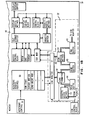
- Fig. 1 is a logical block diagram showing apparatus which may be used in the practice of the present invention.
- Fig. 2 is a logical block diagram of the logic used in the receive formatter system which may be used in combination with the logic shown in Fig. 1.
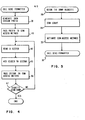
- Fig. 3 is a flow chart showing the general steps involved in recording a machine status or data dump onto a diskette.
- Fig. 4 is a flow chart of the operations of the apparatus during the sending of the data recorded on the dump diskette.
- Fig. 5 is a flow chart of the general steps involved in the initiation and queueing of the dump diskette operation which is then'carried out in accordance with the flow chart of Fig. 4.
- Fig. 6 is a flow chart of the operations involved in receiving data transmitted from another diskette at a remote location and reconstructing the data onto a diskette at the receiving location.
- With reference to Fig. 1, the system of the present invention will be described. 'As a major aspect of the present invention involves communication between two data processors or word processors remote and distant from each other, the invention will be described and illustrated with respect to Fig. 1 which for purposes of the present illustration will consist of two identical word processing work stations or terminals. For example, the
first work station 11 will be in Naples and thesecond work station 10 will be in Austin. In addition, for purposes of this illustration, we will assume that service support to correct and diagnose error and problem conditions is not available in Naples but is available in Austin and that an error or problem in the word processor occurs in Naples. Each of the two word processing work stations is a display terminal work station which has been modified in accordance with the present invention as will be hereinafter described in detail. Since the problem which we assume to occur has occurred inwork station 11 in Naples, we will describe primarily the functional units in the Napleswork station 11. However, it is to be understood that identical units exist in wordprocessing work station 10 in Austin. After we describe the standard functions of these work stations, we will proceed to describe specific units necessary to carry out the various operations of the present invention and will also cover the functions of these units in a series of flow charts. - Now, with reference to Fig. 1,
work stations communication link 12 represented by a bus. Each of the terminals includes acommunications adapter 14 and 114, each respectively connected tocommunication link 12. The communications adapters may be any standard device having capability, at the transmitting end, of converting parallel to serial data so that the data may be communicated over external lines and, at the receiving end, for reconverting the received serial data into parallel form so that it may be handled by the receiving display terminal. These communications adapters will not be described in detail since they are not involved in the present invention which is directed to how the data is transmitted and how transmitted data is handled once it is received at the receiving terminal. - The mode of communication over
communication link 12 which represents a link between the two terminals is a synchronous serial communication. The communication adapter which can be used in the present invention is described in detail in European patent application, assigned to the assignee of the present application. For purposes of describing the communications adapter, said application is hereby incorporated by reference. In addition, the general operations of thedisplay terminals - The following description made with respect to the
second work station 11 is also substantially applicable to thefirst work station 10. Inwork station 11, the operator accesses the machine through operator control keys on akeyboard 15. The keyboard drives aprocessor 16. Theprocessor 16 is operably interconnected into avisual display 17, adiskette 18, and arandom access memory 19 viamemory bus 20. Asystem clock 21 is provided for the timing functions withinwork station 11. The information transmitted fromwork station 11 in Naples toremote display terminal 10 in Austin is serially and synchronously sent overcommunication link 12 from communications adapter 14.Communications adapter 114 does a serial to parallel conversion of the input data and sends it over amemory bus 120 to memory means 119 which has the capability of storing the received data and displaying it at some subsequent time. Memory 119 includes a number of data areas and functional programs for operating with the data input into it throughbus 120 fromcommunications adapter 114. -
Memory 19 ofwork station 11 andmemory 119 ofwork station 10 which are substantially identical in structure contain all of the programming expedients and routines necessary to operate wordprocessing work stations - In addition, the expedients required to carry out the functions of the present invention are also respectively included in
memories memory units send formatting system 22 shown within the dashed lines ofmemory 19, Fig. 1B and the receive formatting system shown in Fig. 2. Although the send formatting and receive formatting systems are only shown with respect tomemory 19 inwork station 11, it is to be understood thatmemory 119 ofword processing station 10 also contains identical send formatting and receive formatting systems. - The logic shown in Fig. 1 will now be considered in connection with the data handling processors which will be subsequently described in connection with the flow charts of Figs. 3 through 6 in order to illustrate how the system of the present invention operates.
- Let us assume that the operator is operating on word
processing work station 11 in Naples when an error condition develops. The operator is incapable of diagnosing his problem. Let us further assume that the problem exists some place inmemory 19 ofwork station 11. Then, with reference to Fig. 3,step 22, the operator presses the dump switch. This is merely a switch on the keyboard or elsewhere in wordprocessing work station 11 which starts the dump procedure shown in Fig. 3 which results in the status of every bit in all of or a selected portion ofmemory 19 being stored onto or dumped onto a diskette. In other words, routine will provide on a diskette a "snap shot" dump giving the status of every bit inmemory 19 of a selected portion of the memory at the time that the error condition arose. The operator pressesdump switch 23, Fig. lA which communicates with theprocessor 16 to activate a conventional routine stored in read only store (ROS)unit 33 resulting in the dump. Because data dumps onto storage means such as disks or diskettes are well known in the art, any conventional expedient for conducting such a data dump may be used. In any event, the dump routine stored inROS 33 is activated fromprocessor 16 overline 24 and communicated fromROS 33 tomemory 19 viabus 25 andbus 20 which results in the status of the total context ofmemory 19 being dumped or loaded upon adiskette 18 viabus 20. - As each unit and section of
memory 19 is dumped upondiskette 18, a decision step 27 (Fig. 3) is made as to whether the dump is complete. If the dump is complete, the routine is ended. If the dump is not complete, an address on the diskette is assigned for the particular portion of the status ofmemory 19 stored ondiskette 18,step 28 and more data indicative of the status ofmemory 19 is written onto the diskette,step 29. - At this point, the status diskette which we will refer to as the dump diskette reflecting the status of
memory 19 during the error condition is to be queued for transmission to wordprocessing work station 10 in Austin so that the service engineering support available in Austin may diagnose the error or problem condition. In order to accomplish this, the dump diskette must be queued for sending. With reference to Fig. 5,step 30, the dump diskette is queued. This is carried out under a standard queueing routine "Send Queue Manager" stored in key stroke service routine, block 50 of Fig. 1B which is under the control of keystroke control block 51. - The next command in the sequence of Fig. 5 is the communication start command, step 31, which activates the
communication monitor 37, Fig. 1B, which in turn activatescommunication access method 34 viabus 35, as set forth in step 32 of Fig. 5. At this point, system is ready to communicate, i.e., transmit the dump disk to wordprocessing work station 10 in Austin. Operator must establishcommunication linkage 12. Then, the "Send Formatter" routine is called,step 36. This "Send Formatter" routine is shown in Fig. 4. This "Send Formatter" routine is carried out by the send formatting system shown in Fig. 1. The operations of the "Send Formatter" routine will now be described using the operations flow chart of Fig. 4 with respect to the operational elements of Fig. 1. First,step 38, the prefix for the data stream to be transmitted or sent is generated. This is done in the "Send Formatter", block 39, and passed to thecommunications access method 34 via thesend buffer 40 as shown instep 41. Next,step 42, a sector is read from thediskette 18 throughdiskette access method 43 into readbuffer 44. Then, step 45, a header which contains control instructions is added to the sector in the read buffer, after which the sector is passed to thecommunications access method 34 in accordance withstep 46. Then, the communications access method sends the data through thelink buffer 48 to the communications adapter 14 through which data on the diskette is sent overcommunication linkage 12 to thecommunications adapter 114 at the receiving wordprocessing work station 10. - Next, a determination is made, step 47, as to whether the entire dump diskette has been sent. If it has not, the operation is branched back to step 42 and the next sector is read. If the operation is complete, then the transmission ends. At this point, complete dump diskette has been sent to the word
processing work station 10 at the remote location where the dump diskette is to be diagnosed. - The reconstruction of the dump diskette, the data of which has been just transmitted will now be described with respect to word
processing work station 10 in Austin. This is carried out using a receive formatting system the logic of which is shown in Fig. 2. It should be noted that the receive formatting system is attached to thecommunication monitor 37 and controlled by it in a fashion similar to the send formatting system. In the present embodiment, each ofwork stations send formatting system 22 shown in Fig. 1 as well as the receive formatting system shown in Fig. 2. For purposes of the present illustrative communication, the receive formatting system inwork station 10 is being considered in Fig. 2. When the data transmitted fromwork station 11 as previously described reaches thecommunication adapter 114 inwork station 10, a data interrupt occurs,step 52, Fig. 6. This results in the receive formatter system of Fig. 2 being called,step 53. A decision is made in the receive formatter system,step 54, as to whether the complete diskette has been received as yet. If it has been received, the transmission is completed and we now have a complete reconstructed diskette. If the complete disk has been received, the routine ends. If the complete disk has not been received as yet, then thecommunication access method 55 fetches the section of data which has been received from thelink buffer 56 and places it in the receive buffer 57 (step 58 in Fig. 6). - At this point a decision is made in receive formatter of block 59 as to whether this is the beginning of a job or function (step 60). If it is the beginning of a job or function, then the formatter 59 processes the previously described prefix (step 61). This involves an initiation step wherein the receiving disk medium is checked for compatibility with its equivalent medium at the transmitting end, e.g., since the disk or diskette is to be reconstructed at the receiving end, the disk medium at the receiving end is checked to see if it has equivalent structural properties such as size. In addition, a determination is made as to whether there are any optional information messages to be retrieved from the prefix and displayed on the display terminal of the receiving word processing station. Next, after the prefix has been processed or if it is not the start of a job, step 62 is carried out in formatter 59 and the sector header on the disk is removed. Next,
step 63, next sector is written on the disk through thewrite buffer 64 communicating with thediskette access method 65 which in turn accesses disk 118 overbus 120. - This procedure is continued until the data representative of the dumped diskette from word
processing work station 11 is received and recorded on a diskette 118 in remote wordprocessing work station 10. We now have at work station 10 a complete reconstruction of the dumped diskette formed atwork station 11. This diskette is now available for any conventional diagnostics which the service engineering personnel at thework station 10 location may wish to carry out either usingword processor station 10 or any other diagnostic equipment. - Because diagnosis of data dumps for error and problem detection is an extensive and varied technology and is dependent on the nature of the application involved in the processor having the error condition, we will not here attempt to suggest any particular diagnostic technique which may be used on the data dump contained on the reconstructed diskette at
work station 10. In any event, service engineering personnel atwork station 10 using suitable conventional diagnostic techniques which would be essentially the same had they been available atwork station 11 to deal directly with the original dump diskette now proceed to diagnosis and correct the problem. - Upon correction of the problem, they may now provide at
work station 10 an initial correction diskette. This correction diskette may provide a status condition for all or any part ofmemory 19 in which the error occurred. This correction diskette when made available tomemory 19 inwork station 11 will correct the error condition inmemory 19 and, thus,permit work station 11 in Naples to resume normal operations. The initial correction diskette made in connection withwork station 10 in Austin may now be transmitted to workstation 11 in Naples and based upon the data transmitted fromwork station 10, the wordprocessor work station 11 can reconstruct the correction diskette and make it available for insertion of the correction status intomemory 19. - Transmission of the data on the initial correction diskette formed at
work station 10 to workstation 11 may be carried out using the same procedures set forth hereinabove for the transmission of the data on the dump diskette fromwork station 11 to workstation 10. The data thus transmitted may be rerecorded on a reconstructed correction diskette atwork station 11 in Naples which is a full replica of the initial correction diskette formed atwork station 10 in Austin. The reconstructed correction diskette when unloaded intomemory 19 atwork station 11 will correct the error status andpermit work station 10 to resume its normal operation. - In the present application, the terms disk and diskettes have been used to describe magnetic storage media. However, only the term disk has been used in the claims wherein the term is used in its generic sense to cover both conventional disks and diskettes.
- While the invention has been particularly shown and described with reference to a preferred embodiment it will be understood by those skilled in the art that various other changes in form and detail may be made without departing from the spirit and scope of the invention.
Claims (7)
Applications Claiming Priority (2)
| Application Number | Priority Date | Filing Date | Title |
|---|---|---|---|
| US280023 | 1981-06-30 | ||
| US06/280,023 US4463418A (en) | 1981-06-30 | 1981-06-30 | Error correction from remote data processor by communication and reconstruction of processor status storage disk |
Publications (3)
| Publication Number | Publication Date |
|---|---|
| EP0068108A2 true EP0068108A2 (en) | 1983-01-05 |
| EP0068108A3 EP0068108A3 (en) | 1986-02-05 |
| EP0068108B1 EP0068108B1 (en) | 1989-03-08 |
Family
ID=23071303
Family Applications (1)
| Application Number | Title | Priority Date | Filing Date |
|---|---|---|---|
| EP82103878A Expired EP0068108B1 (en) | 1981-06-30 | 1982-05-05 | System and process for diagnosing and correcting errors in a remote data processing equipment |
Country Status (8)
| Country | Link |
|---|---|
| US (1) | US4463418A (en) |
| EP (1) | EP0068108B1 (en) |
| JP (1) | JPS585859A (en) |
| AU (1) | AU544805B2 (en) |
| BR (1) | BR8203724A (en) |
| CA (1) | CA1169568A (en) |
| DE (1) | DE3279516D1 (en) |
| ES (1) | ES513517A0 (en) |
Cited By (6)
| Publication number | Priority date | Publication date | Assignee | Title |
|---|---|---|---|---|
| EP0333620A2 (en) * | 1988-03-17 | 1989-09-20 | International Business Machines Corporation | On-line problem management for data-processing systems |
| EP1117232A2 (en) * | 2000-01-11 | 2001-07-18 | Siemens Information and Communication Networks Inc. | System and method for digital telephone trouble reporting |
| WO2011020051A1 (en) * | 2009-08-13 | 2011-02-17 | Qualcomm Incorporated | Apparatus and method for distributed data processing |
| US8762532B2 (en) | 2009-08-13 | 2014-06-24 | Qualcomm Incorporated | Apparatus and method for efficient memory allocation |
| US8788782B2 (en) | 2009-08-13 | 2014-07-22 | Qualcomm Incorporated | Apparatus and method for memory management and efficient data processing |
| US9038073B2 (en) | 2009-08-13 | 2015-05-19 | Qualcomm Incorporated | Data mover moving data to accelerator for processing and returning result data based on instruction received from a processor utilizing software and hardware interrupts |
Families Citing this family (37)
| Publication number | Priority date | Publication date | Assignee | Title |
|---|---|---|---|---|
| US4672574A (en) * | 1981-06-16 | 1987-06-09 | International Business Machines Corporation | Data communication system with terminal for displaying the coded stream of data being transmitted |
| JPS59123058A (en) * | 1982-12-29 | 1984-07-16 | Fujitsu Ltd | Machine check processing system |
| US5038319A (en) * | 1989-04-24 | 1991-08-06 | Xerox Corporation | System for recording and remotely accessing operating data in a reproduction machine |
| US6009284A (en) * | 1989-12-13 | 1999-12-28 | The Weinberger Group, L.L.C. | System and method for controlling image processing devices from a remote location |
| US5214772A (en) * | 1989-12-13 | 1993-05-25 | Joseph Weinberger | System for automatically monitoring copiers from a remote location |
| US5333286A (en) * | 1989-12-13 | 1994-07-26 | Joseph Weinberger | Two way copier monitoring system |
| US5084875A (en) * | 1989-12-13 | 1992-01-28 | Joseph Weinberger | System for automatically monitoring copiers from a remote location |
| JPH0815277B2 (en) * | 1991-08-09 | 1996-02-14 | インターナショナル・ビジネス・マシーンズ・コーポレイション | System and method for obtaining performance measurements |
| US6145088A (en) * | 1996-06-18 | 2000-11-07 | Ontrack Data International, Inc. | Apparatus and method for remote data recovery |
| AU716035B2 (en) * | 1996-06-18 | 2000-02-17 | Ontrack Data International, Inc. | Apparatus and method for remote data recovery |
| DE69833817T2 (en) * | 1997-09-02 | 2007-03-29 | Johnson, R. Brent, Tulsa | Emulation and emulated screen history |
| US6622264B1 (en) | 1999-10-28 | 2003-09-16 | General Electric Company | Process and system for analyzing fault log data from a machine so as to identify faults predictive of machine failures |
| US6947797B2 (en) * | 1999-04-02 | 2005-09-20 | General Electric Company | Method and system for diagnosing machine malfunctions |
| US6636771B1 (en) | 1999-04-02 | 2003-10-21 | General Electric Company | Method and system for analyzing continuous parameter data for diagnostics and repairs |
| US6336065B1 (en) | 1999-10-28 | 2002-01-01 | General Electric Company | Method and system for analyzing fault and snapshot operational parameter data for diagnostics of machine malfunctions |
| US7783507B2 (en) * | 1999-08-23 | 2010-08-24 | General Electric Company | System and method for managing a fleet of remote assets |
| US6263265B1 (en) | 1999-10-01 | 2001-07-17 | General Electric Company | Web information vault |
| US20110208567A9 (en) * | 1999-08-23 | 2011-08-25 | Roddy Nicholas E | System and method for managing a fleet of remote assets |
| CA2783174A1 (en) | 1999-10-28 | 2001-05-10 | General Electric Company | Method and system for remotely managing communication of data used for predicting malfunctions in a plurality of machines |
| US6324659B1 (en) | 1999-10-28 | 2001-11-27 | General Electric Company | Method and system for identifying critical faults in machines |
| US6543007B1 (en) | 1999-10-28 | 2003-04-01 | General Electric Company | Process and system for configuring repair codes for diagnostics of machine malfunctions |
| US6338152B1 (en) | 1999-10-28 | 2002-01-08 | General Electric Company | Method and system for remotely managing communication of data used for predicting malfunctions in a plurality of machines |
| US6446026B1 (en) | 1999-10-28 | 2002-09-03 | General Electric Company | Method and system for identifying performance degradation of a cooling subsystem in a locomotive |
| US6643801B1 (en) | 1999-10-28 | 2003-11-04 | General Electric Company | Method and system for estimating time of occurrence of machine-disabling failures |
| US6651034B1 (en) * | 1999-10-28 | 2003-11-18 | General Electric Company | Apparatus and method for performance and fault data analysis |
| US6286479B1 (en) | 1999-10-28 | 2001-09-11 | General Electric Company | Method and system for predictably assessing performance of a fuel pump in a locomotive |
| US6625589B1 (en) | 1999-10-28 | 2003-09-23 | General Electric Company | Method for adaptive threshold computation for time and frequency based anomalous feature identification in fault log data |
| US6959235B1 (en) * | 1999-10-28 | 2005-10-25 | General Electric Company | Diagnosis and repair system and method |
| US6795935B1 (en) | 1999-10-28 | 2004-09-21 | General Electric Company | Diagnosis of faults in a complex system |
| US6615367B1 (en) * | 1999-10-28 | 2003-09-02 | General Electric Company | Method and apparatus for diagnosing difficult to diagnose faults in a complex system |
| US6405108B1 (en) | 1999-10-28 | 2002-06-11 | General Electric Company | Process and system for developing predictive diagnostics algorithms in a machine |
| EP2319472B1 (en) | 1999-12-29 | 2016-03-23 | Hill-Rom Services, Inc. | Patient support |
| US6993675B2 (en) * | 2002-07-31 | 2006-01-31 | General Electric Company | Method and system for monitoring problem resolution of a machine |
| US6810312B2 (en) * | 2002-09-30 | 2004-10-26 | General Electric Company | Method for identifying a loss of utilization of mobile assets |
| FR2882448B1 (en) * | 2005-01-21 | 2007-05-04 | Meiosys Soc Par Actions Simpli | METHOD OF MANAGING, JOURNALIZING OR REJECTING THE PROGRESS OF AN APPLICATION PROCESS |
| US8560903B2 (en) | 2010-08-31 | 2013-10-15 | Cisco Technology, Inc. | System and method for executing functional scanning in an integrated circuit environment |
| US8560474B2 (en) | 2011-03-07 | 2013-10-15 | Cisco Technology, Inc. | System and method for providing adaptive manufacturing diagnoses in a circuit board environment |
Citations (1)
| Publication number | Priority date | Publication date | Assignee | Title |
|---|---|---|---|---|
| US4057847A (en) * | 1976-06-14 | 1977-11-08 | Sperry Rand Corporation | Remote controlled test interface unit |
Family Cites Families (20)
| Publication number | Priority date | Publication date | Assignee | Title |
|---|---|---|---|---|
| US3325788A (en) * | 1964-12-21 | 1967-06-13 | Ibm | Extrinsically variable microprogram controls |
| US3343141A (en) * | 1964-12-23 | 1967-09-19 | Ibm | Bypassing of processor sequence controls for diagnostic tests |
| US3564509A (en) * | 1968-04-22 | 1971-02-16 | Burroughs Corp | Data processing apparatus |
| US3585599A (en) * | 1968-07-09 | 1971-06-15 | Ibm | Universal system service adapter |
| US3676846A (en) * | 1968-10-08 | 1972-07-11 | Call A Computer Inc | Message buffering communication system |
| US3767901A (en) * | 1971-01-11 | 1973-10-23 | Walt Disney Prod | Digital animation apparatus and methods |
| US3805038A (en) * | 1972-07-12 | 1974-04-16 | Gte Automatic Electric Lab Inc | Data handling system maintenance arrangement for processing system fault conditions |
| US3784801A (en) * | 1972-07-12 | 1974-01-08 | Gte Automatic Electric Lab Inc | Data handling system error and fault detecting and discriminating maintenance arrangement |
| US3910322A (en) * | 1972-08-24 | 1975-10-07 | Westinghouse Electric Corp | Test set controlled by a remotely positioned digital computer |
| US3889062A (en) * | 1972-10-02 | 1975-06-10 | Action Communication Systems I | System and method for coupling remote data terminals via telephone lines |
| US3825901A (en) * | 1972-11-09 | 1974-07-23 | Ibm | Integrated diagnostic tool |
| US3916177A (en) * | 1973-12-10 | 1975-10-28 | Honeywell Inf Systems | Remote entry diagnostic and verification procedure apparatus for a data processing unit |
| US3940744A (en) * | 1973-12-17 | 1976-02-24 | Xerox Corporation | Self contained program loading apparatus |
| US3909802A (en) * | 1974-04-08 | 1975-09-30 | Honeywell Inf Systems | Diagnostic maintenance and test apparatus |
| US3958111A (en) * | 1975-03-20 | 1976-05-18 | Bell Telephone Laboratories, Incorporated | Remote diagnostic apparatus |
| JPS5399739A (en) * | 1977-02-12 | 1978-08-31 | Nippon Telegr & Teleph Corp <Ntt> | Terminal remote diagnostic system |
| JPS53105149A (en) * | 1977-02-24 | 1978-09-13 | Nec Corp | Romote maintenance system |
| US4225918A (en) * | 1977-03-09 | 1980-09-30 | Giddings & Lewis, Inc. | System for entering information into and taking it from a computer from a remote location |
| JPS55112657A (en) * | 1979-02-22 | 1980-08-30 | Nec Corp | Computer inspection unit |
| US4322846A (en) * | 1980-04-15 | 1982-03-30 | Honeywell Information Systems Inc. | Self-evaluation system for determining the operational integrity of a data processing system |
-
1981
- 1981-06-30 US US06/280,023 patent/US4463418A/en not_active Expired - Lifetime
-
1982
- 1982-03-23 CA CA000399180A patent/CA1169568A/en not_active Expired
- 1982-05-05 DE DE8282103878T patent/DE3279516D1/en not_active Expired
- 1982-05-05 EP EP82103878A patent/EP0068108B1/en not_active Expired
- 1982-05-14 AU AU83711/82A patent/AU544805B2/en not_active Ceased
- 1982-05-20 JP JP57084118A patent/JPS585859A/en active Granted
- 1982-06-25 BR BR8203724A patent/BR8203724A/en not_active IP Right Cessation
- 1982-06-28 ES ES513517A patent/ES513517A0/en active Granted
Patent Citations (1)
| Publication number | Priority date | Publication date | Assignee | Title |
|---|---|---|---|---|
| US4057847A (en) * | 1976-06-14 | 1977-11-08 | Sperry Rand Corporation | Remote controlled test interface unit |
Non-Patent Citations (3)
| Title |
|---|
| HEWLETT-PACKARD JOURAL, September 1979, pages 13-16, Palo Alto, US; D.L. NELSON: "A remote computer troubleshooting facility" * |
| IBM TECHNICAL DISCLOSURE BULLETIN, vol. 22, no. 3, August 1979, pages 1129-1130, New York, US; B.B. MOORE et al.: "Dumping of inaccessible handware storage areas" * |
| THE EIGHT ANNUAL INTERNATIONAL CONFERENCE ON FAULT-TOLERANT COMPUTING, Toulouse, France, 21st-23st June 1978, pages 24-28, IEEE, Piscataway, US; R.S. SWARZ: "Reliability and maintainability enhancements for the vax-11/780" * |
Cited By (9)
| Publication number | Priority date | Publication date | Assignee | Title |
|---|---|---|---|---|
| EP0333620A2 (en) * | 1988-03-17 | 1989-09-20 | International Business Machines Corporation | On-line problem management for data-processing systems |
| EP0333620A3 (en) * | 1988-03-17 | 1991-03-20 | International Business Machines Corporation | On-line problem management for data-processing systems |
| US5287505A (en) * | 1988-03-17 | 1994-02-15 | International Business Machines Corporation | On-line problem management of remote data processing systems, using local problem determination procedures and a centralized database |
| EP1117232A2 (en) * | 2000-01-11 | 2001-07-18 | Siemens Information and Communication Networks Inc. | System and method for digital telephone trouble reporting |
| EP1117232A3 (en) * | 2000-01-11 | 2010-11-10 | Siemens Communications, Inc. | System and method for digital telephone trouble reporting |
| WO2011020051A1 (en) * | 2009-08-13 | 2011-02-17 | Qualcomm Incorporated | Apparatus and method for distributed data processing |
| US8762532B2 (en) | 2009-08-13 | 2014-06-24 | Qualcomm Incorporated | Apparatus and method for efficient memory allocation |
| US8788782B2 (en) | 2009-08-13 | 2014-07-22 | Qualcomm Incorporated | Apparatus and method for memory management and efficient data processing |
| US9038073B2 (en) | 2009-08-13 | 2015-05-19 | Qualcomm Incorporated | Data mover moving data to accelerator for processing and returning result data based on instruction received from a processor utilizing software and hardware interrupts |
Also Published As
| Publication number | Publication date |
|---|---|
| BR8203724A (en) | 1983-06-21 |
| AU544805B2 (en) | 1985-06-13 |
| DE3279516D1 (en) | 1989-04-13 |
| CA1169568A (en) | 1984-06-19 |
| JPS631628B2 (en) | 1988-01-13 |
| ES8400617A1 (en) | 1983-10-16 |
| JPS585859A (en) | 1983-01-13 |
| EP0068108A3 (en) | 1986-02-05 |
| AU8371182A (en) | 1983-01-06 |
| EP0068108B1 (en) | 1989-03-08 |
| US4463418A (en) | 1984-07-31 |
| ES513517A0 (en) | 1983-10-16 |
Similar Documents
| Publication | Publication Date | Title |
|---|---|---|
| US4463418A (en) | Error correction from remote data processor by communication and reconstruction of processor status storage disk | |
| US4653112A (en) | Image data management system | |
| US4437184A (en) | Method of testing a data communication system | |
| US20030023791A1 (en) | Device driver apparatus | |
| US4672574A (en) | Data communication system with terminal for displaying the coded stream of data being transmitted | |
| US20050144339A1 (en) | Speculative processing of transaction layer packets | |
| US4985894A (en) | Fault information collection processing system | |
| US4855900A (en) | System for transferring data to a mainframe computer | |
| EP0503920A2 (en) | Apparatus and system for providing diagnostic support to one or more computer systems | |
| JP2738173B2 (en) | Diagnostic system for stand-alone equipment | |
| JP2776679B2 (en) | Information processing system | |
| JPS6245266A (en) | Method for remote fault diagnosis and fault repair of communication terminal equipment | |
| EP0378398A2 (en) | Data processing system with means for detecting status of data processing device receiving commands | |
| JPH0426500B2 (en) | ||
| JPS59181860A (en) | Diagnostic system of communication controller | |
| JP2858135B2 (en) | Method and apparatus for diagnosing connection between line controllers | |
| JPH039439A (en) | Diagnostic control system | |
| JPS63181057A (en) | System for testing communication control program | |
| JPH0362752A (en) | Communication system | |
| JP3372192B2 (en) | Bus interface test method and recording medium storing the processing program | |
| Austin et al. | Linking a CYBER76 to a 3600 | |
| JPS5949611B2 (en) | Communication control device diagnostic processing method | |
| JPS58182988A (en) | Remote file transfer system | |
| EP0046466A1 (en) | A method of testing a data communication system | |
| JPS60136838A (en) | Information storage device |
Legal Events
| Date | Code | Title | Description |
|---|---|---|---|
| PUAI | Public reference made under article 153(3) epc to a published international application that has entered the european phase |
Free format text: ORIGINAL CODE: 0009012 |
|
| AK | Designated contracting states |
Designated state(s): BE CH DE FR GB IT LI NL SE |
|
| 17P | Request for examination filed |
Effective date: 19830420 |
|
| PUAL | Search report despatched |
Free format text: ORIGINAL CODE: 0009013 |
|
| AK | Designated contracting states |
Designated state(s): BE CH DE FR GB IT LI NL SE |
|
| 17Q | First examination report despatched |
Effective date: 19870602 |
|
| GRAA | (expected) grant |
Free format text: ORIGINAL CODE: 0009210 |
|
| AK | Designated contracting states |
Kind code of ref document: B1 Designated state(s): BE CH DE FR GB IT LI NL SE |
|
| REF | Corresponds to: |
Ref document number: 3279516 Country of ref document: DE Date of ref document: 19890413 |
|
| ET | Fr: translation filed | ||
| ITF | It: translation for a ep patent filed |
Owner name: IBM - DR. ALFREDO BRAVI |
|
| PLBE | No opposition filed within time limit |
Free format text: ORIGINAL CODE: 0009261 |
|
| STAA | Information on the status of an ep patent application or granted ep patent |
Free format text: STATUS: NO OPPOSITION FILED WITHIN TIME LIMIT |
|
| 26N | No opposition filed | ||
| ITTA | It: last paid annual fee | ||
| PGFP | Annual fee paid to national office [announced via postgrant information from national office to epo] |
Ref country code: CH Payment date: 19930811 Year of fee payment: 12 |
|
| PGFP | Annual fee paid to national office [announced via postgrant information from national office to epo] |
Ref country code: BE Payment date: 19940415 Year of fee payment: 13 |
|
| PGFP | Annual fee paid to national office [announced via postgrant information from national office to epo] |
Ref country code: SE Payment date: 19940518 Year of fee payment: 13 |
|
| PG25 | Lapsed in a contracting state [announced via postgrant information from national office to epo] |
Ref country code: LI Effective date: 19940531 Ref country code: CH Effective date: 19940531 |
|
| PGFP | Annual fee paid to national office [announced via postgrant information from national office to epo] |
Ref country code: NL Payment date: 19940531 Year of fee payment: 13 |
|
| EAL | Se: european patent in force in sweden |
Ref document number: 82103878.3 |
|
| REG | Reference to a national code |
Ref country code: CH Ref legal event code: PL |
|
| PGFP | Annual fee paid to national office [announced via postgrant information from national office to epo] |
Ref country code: FR Payment date: 19950427 Year of fee payment: 14 |
|
| PG25 | Lapsed in a contracting state [announced via postgrant information from national office to epo] |
Ref country code: SE Effective date: 19950506 |
|
| PG25 | Lapsed in a contracting state [announced via postgrant information from national office to epo] |
Ref country code: BE Effective date: 19950531 |
|
| BERE | Be: lapsed |
Owner name: INTERNATIONAL BUSINESS MACHINES CORP. Effective date: 19950531 |
|
| PG25 | Lapsed in a contracting state [announced via postgrant information from national office to epo] |
Ref country code: NL Effective date: 19951201 |
|
| NLV4 | Nl: lapsed or anulled due to non-payment of the annual fee |
Effective date: 19951201 |
|
| EUG | Se: european patent has lapsed |
Ref document number: 82103878.3 |
|
| PG25 | Lapsed in a contracting state [announced via postgrant information from national office to epo] |
Ref country code: FR Effective date: 19970131 |
|
| REG | Reference to a national code |
Ref country code: FR Ref legal event code: ST |
|
| PGFP | Annual fee paid to national office [announced via postgrant information from national office to epo] |
Ref country code: GB Payment date: 20010514 Year of fee payment: 20 |
|
| PGFP | Annual fee paid to national office [announced via postgrant information from national office to epo] |
Ref country code: DE Payment date: 20010914 Year of fee payment: 20 |
|
| REG | Reference to a national code |
Ref country code: GB Ref legal event code: IF02 |
|
| PG25 | Lapsed in a contracting state [announced via postgrant information from national office to epo] |
Ref country code: GB Free format text: LAPSE BECAUSE OF EXPIRATION OF PROTECTION Effective date: 20020504 |
|
| REG | Reference to a national code |
Ref country code: GB Ref legal event code: PE20 Effective date: 20020504 |