EP0069653A1 - Device for mounting an information panel, panel and intermediate part belonging to it - Google Patents
Device for mounting an information panel, panel and intermediate part belonging to it Download PDFInfo
- Publication number
- EP0069653A1 EP0069653A1 EP82401221A EP82401221A EP0069653A1 EP 0069653 A1 EP0069653 A1 EP 0069653A1 EP 82401221 A EP82401221 A EP 82401221A EP 82401221 A EP82401221 A EP 82401221A EP 0069653 A1 EP0069653 A1 EP 0069653A1
- Authority
- EP
- European Patent Office
- Prior art keywords
- arm
- panel
- post
- screw
- slide
- Prior art date
- Legal status (The legal status is an assumption and is not a legal conclusion. Google has not performed a legal analysis and makes no representation as to the accuracy of the status listed.)
- Granted
Links
Images


Classifications
-
- G—PHYSICS
- G09—EDUCATION; CRYPTOGRAPHY; DISPLAY; ADVERTISING; SEALS
- G09F—DISPLAYING; ADVERTISING; SIGNS; LABELS OR NAME-PLATES; SEALS
- G09F7/00—Signs, name or number plates, letters, numerals, or symbols; Panels or boards
- G09F7/18—Means for attaching signs, plates, panels, or boards to a supporting structure
- G09F7/20—Means for attaching signs, plates, panels, or boards to a supporting structure for adjustably mounting
Definitions
- the present invention relates to a device for mounting an information panel on a support.
- the invention also relates to a panel intended to be installed by means of such a device, as well as an intermediate piece necessary in the case where the support is a surface such as a wall.
- Another type of fixing applied in particular in the case of multiple superposed panels and having a notable thickness, such as light panels, consists in constituting the post, from a certain height, along a rod of small diameter on which are threaded panels pierced in their thickness, with spacer interposition.
- Such an embodiment relatively aesthetic, is quite expensive.
- adding an additional panel practically requires replacing the post.
- Another known solution consists in constituting the arm by two shells articulated at one end of the arm by means of a screw forming a hinge pin and each comprising an internal face having a recess, the two recesses facing each other to constitute, in closed position of the arm, a cavity for the passage of a cylindrical support. Locking means are provided to keep the two shells in the closed position.
- the present invention aims to achieve an economical device which allows the installation of a panel on any post of usual dimensions, round or polygonal, leaving the possibility of multiple adjustments, and which allows easy disassembly, as well as the addition additional panels.
- the arm can be fixed to any post, round or polygonal, provided that its diameter is less than that of the cavity.
- the locking means comprise a threaded guided part provided with a V-shaped part, and cooperating with a screw immobilized axially with respect to the arm.
- the two shells are hinged together by means of a screw forming a hinge pin, the locking means keeping the shells tight against one another comprising a similar screw and similarly arranged at the opposite end of the arm.
- mounting can be done by opening the arm around one axis or the other.
- the device is characterized in that the arm comprises a lug to cooperate with a slide extending along the panel and this post is rotatably mounted on the arm to allow rotation of the panel relative to the arm.
- the indicator panel intended for fixing to a support by means of a device as described above is characterized in that it comprises, on at least one of its horizontal edges, a slide formed by two wings facing each other to cooperate with the tenon of the arm.
- the intermediate piece for fixing an indicator panel to a wall by means of a device as described above is characterized in that it comprises a substantially flat face provided with fixing holes in said wall, and a cylindrical part for cooperating with the cavity of the arm.
- an arm 1 comprises two shells 2a, 2b assembled by means of two screws 3a, 3b each located at one end of the arm. For clarity, these screws are only shown in Figure 4.
- the shell 2a (the only one shown in FIG. 1, the shell 2b being supposed to have been removed) has teeth 4a forming a cutout in Greek, between which come teeth 4b of the shell 2b (FIG. 4) arranged with similar way.
- the teeth 4a and 4b are pierced with smooth holes 5, except, at each end of the arm 1, an end tooth of the shell 2a which includes a tapping 6. In the example described, this tapping is reported.
- the screws 3a, 3b pass through the holes 5 and are screwed into the threads 6.
- Each shell has a substantially semi-cylindrical recess, respectively 7a, 7b. These recesses are arranged to face each other when the shells are assembled ( Figure 2) and constitute a cylindrical cavity allowing the passage of any sign post, cylindrical or polygonal, of usual diameter.
- Two half-cylinders 8a, 8b formed in webs 9a, 9b of each shell constitute, once the shell has been assembled, a bearing for a smooth bearing 11 of a screw 12 provided with a hexagonal section 13.
- the screw 12 is held axially by a circlip 14.
- This screw cooperates with a thread 15 of a part 16 slidingly mounted in the shells.
- the shells carry slides 17a, 17b T-shaped ( Figure 3).
- the part 16 comprises on one side a T-shaped notch to cooperate with the slide 17b and, on the other side, a wide notch 18 allowing the wings of the slide 17a to pass.
- a cylindrical part 23 bears on the shells by a shoulder 24.
- This part is crossed axially by a screw 25 which cooperates with a tapping 26 of a nut 27 of which is integral a tenon 28.
- the nut 27 comprises a conical bearing 29 made of plastic material which cooperates with a conical cavity 23a of the part 23.
- the lug 28 which projects out of the arm on the side opposite to the head of the screw 25, cooperates with a slide 31 of an indicator panel 32 (FIG. 6).
- This slide is formed by two wings making face and extending on a horizontal base (in service position) of the panel.
- the tenon 28 can rotate around the axis of the screw 25 and can also slide in the slide 31.
- the dimensions of the arm and the stroke of the locking screw 12 are such that the arm can be fixed to any post with a diameter between 70 and 120 mm, possibly polygonal.
- This part is constituted by a bottom 34 surrounded on three sides by two side walls 35 and by a transverse wall 36.
- the latter is provided with holes 37 for fixing bolts in the wall.
- the side walls 35 leave a clearance sufficient to allow significant freedom of orientation of the arm, to which is added the freedom of translation of the panel.
Abstract
Description
La présente invention concerne un dispositif de montage de panneau d'information sur un support.The present invention relates to a device for mounting an information panel on a support.
L'invention concerne également un panneau prévu pour être installé par l'intermédiaire d'un tel dispositif, ainsi qu'une pièce intermédiaire nécessaire dans le cas où le support est une surface telle qu'un mur.The invention also relates to a panel intended to be installed by means of such a device, as well as an intermediate piece necessary in the case where the support is a surface such as a wall.
Les panneaux indicateurs sont le plus souvent fixés sur des poteaux. La fixation la plus économique consiste en des colliersà pattes qui nécessitent le perçage du panneau en des emplacements définitifs ne permettant plus, par la suite, que le seul déplacement rotatif autour du poteau, malgré l'inconvénient qui peut en résulter si des panneaux supplémentaires doivent être installés par la suite. En outre, il est nécessaire de disposer d'un jeu de colliers de divers diamètres pour s'adapter à différents types de poteau existants ou non.Signs are most often attached to poles. The most economical fixing consists of leg collars which require the panel to be drilled in definitive locations, thereafter allowing only the only rotary movement around the post, despite the drawback which may result if additional panels have to be be installed afterwards. In addition, it is necessary to have a set of collars of various diameters to adapt to different types of post existing or not.
Un autre type de fixation, appliqué notamment dans le cas de panneaux multiples superposés et présentant une épaisseur notable, tels que les panneaux lumineux, consiste à constituer le poteau, à partir d'une certaine hauteur, suivant une tige de faible diamètre sur laquelle sont enfilés les panneaux percés dans leur épaisseur, avec interposition d'entretoise. Une telle réalisation, relativement esthétique, est assez coûteuse. En outre, une fois les panneaux percés, elle ne permet plus qu'un réglage en rotation. Enfin., l'adjonction d'un panneau supplémentaire nécessite pratiquement de remplacer le poteau.Another type of fixing, applied in particular in the case of multiple superposed panels and having a notable thickness, such as light panels, consists in constituting the post, from a certain height, along a rod of small diameter on which are threaded panels pierced in their thickness, with spacer interposition. Such an embodiment, relatively aesthetic, is quite expensive. In addition, once the panels are drilled, it only allows an adjustment in rotation. Finally, adding an additional panel practically requires replacing the post.
Une autre solution connue consiste à constituer le bras par deux coquilles articulées à une extrémité du bras au moyen d'une vis formant axe d'articulation et comportant chacune une face interne présentant un évidement, les deux évidements se faisant face pour constituer, en position fermée du bras, une cavité pour le passage d'un support cylindrique. Des moyens de verrouillage sont prévus pour maintenir les deux coquilles en position fermée.Another known solution consists in constituting the arm by two shells articulated at one end of the arm by means of a screw forming a hinge pin and each comprising an internal face having a recess, the two recesses facing each other to constitute, in closed position of the arm, a cavity for the passage of a cylindrical support. Locking means are provided to keep the two shells in the closed position.
Cette solution nécessite que la cavité du bras s'adapte assez exactement au support, donc que ce dernier soit cylindrique, sensiblement au diamètre de la cavité. Il faut donc prévoir un type précis de support.This solution requires that the arm cavity adapts fairly exactly to the support, therefore that the latter is cylindrical, substantially to the diameter of the cavity. It is therefore necessary to provide a specific type of support.
La présente invention vise à réaliser un dispositif économique qui permette l'installation d'un panneau sur un poteau quelconque de dimensions usuelles, rond ou polygonal, en laissant la possibilité de multiples réglages, et qui permette un démontage facile, ainsi que l'adjonction de panneaux supplémentaires.The present invention aims to achieve an economical device which allows the installation of a panel on any post of usual dimensions, round or polygonal, leaving the possibility of multiple adjustments, and which allows easy disassembly, as well as the addition additional panels.
Ce résultat est obtenu, conformément à l'invention, grâce à des moyens de blocage du bras sur le support cylindrique.This result is obtained, in accordance with the invention, by means of blocking the arm on the cylindrical support.
Grâce à ces moyens de blocage, le bras peut être fixé sur tout poteau, rond ou polygonal, pourvu que son diamètre soit inférieur à celui de la cavité.Thanks to these blocking means, the arm can be fixed to any post, round or polygonal, provided that its diameter is less than that of the cavity.
Suivant une réalisation préférée de l'invention les moyens de blocage comprennent une pièce taraudée guidée munie d'une partie en V, et coopérant avec une vis immobilisée axialement par rapport au bras.According to a preferred embodiment of the invention, the locking means comprise a threaded guided part provided with a V-shaped part, and cooperating with a screw immobilized axially with respect to the arm.
Suivant une réalisation avantageuse de l'invention, les deux coquilles sont articulées entre elles par l'intermédiaire d'une vis formant axe d'articulation, les moyens de verrouillage maintenant les coquilles serrées l'une contre l'autre comprenant une vis similaire et similairement disposée à l'extrémité opposée du bras.According to an advantageous embodiment of the invention, the two shells are hinged together by means of a screw forming a hinge pin, the locking means keeping the shells tight against one another comprising a similar screw and similarly arranged at the opposite end of the arm.
Suivant l'espace disponible autour du poteau, on peut réaliser le montage en ouvrant le bras autour d'un axe ou de l'autre.Depending on the space available around the post, mounting can be done by opening the arm around one axis or the other.
Suivant une réalisation perfectionnée de l'invention, le dispositif est caractérisé en ce que le bras comprend un tenon pour coopérer avec une glissière s'étendant le long du panneau et ce tenon est monté rotativement sur le bras pour permettre une rotation du panneau par rapport au bras.According to an improved embodiment of the invention, the device is characterized in that the arm comprises a lug to cooperate with a slide extending along the panel and this post is rotatably mounted on the arm to allow rotation of the panel relative to the arm.
On peut donc, sur place et à la demande, fixer le bras en n'importe quel point du panneau et orienter ce dernier à volonté.We can therefore, on site and on demand, fix the arm at any point of the panel and orient the latter at will.
Suivant un autre aspect de l'invention, le panneau indicateur prévu pour fixation sur un support au moyen d'un dispositif tel que décrit plus haut est caractérisé en ce qu'il comprend, sur au moins l'un de ses bords horizontaux, une glissière formée de deux ailes se faisant face pour coopérer avec le tenon du bras.According to another aspect of the invention, the indicator panel intended for fixing to a support by means of a device as described above is characterized in that it comprises, on at least one of its horizontal edges, a slide formed by two wings facing each other to cooperate with the tenon of the arm.
Suivant un troisième aspect de l'invention, la pièce intermédiaire pour fixation d'un panneau indicateur sur une paroi au moyen d'un dispositif tel que décrit plus haut est caractérisée en ce qu'elle comprend une face sensiblement plane munie de trous de fixation dans ladite paroi, et une partie cylindrique pour coopérer avec la cavité du bras.According to a third aspect of the invention, the intermediate piece for fixing an indicator panel to a wall by means of a device as described above is characterized in that it comprises a substantially flat face provided with fixing holes in said wall, and a cylindrical part for cooperating with the cavity of the arm.
Grâce à cette pièce, on ramène le problème de la fixation sur un mur à celui de la fixation sur un poteau, dont le rôle est joué par la partie cylindrique.Thanks to this piece, the problem of fixing on a wall is reduced to that of fixing on a post, the role of which is played by the cylindrical part.
D'autres particularités et avantages de l'invention ressortiront encore de la description détaillée qui va suivre.Other features and advantages of the invention will emerge from the detailed description which follows.
Aux dessins annexés, donnés à titre d'exemple non limitatif:
- - la figure 1 est une vue en coupe longitudinale du bras, suivant I-I de la figure 2,
- - la figure 2 est une vue en coupe horizontale suivant II-II de la figure 1,
- - la figure 3 est une vue en coupe transversale suivant III-III des figures 1 et 2,
- - la figure 4 est une vue en bout suivant IV-IV des figures 1 et 2,
- - la figure 5 est une vue en perspective du bras ouvert,
- - la figure 6 est une vue en coupe du panneau engagé sur le tenon,
- - la figure 7 est une vue en perspective d'un certain nombre de panneaux montés sur un poteau,
- - la figure 8 est une vue en coupe longitudinale de la pièce intermédiaire, suivant VIII-VIII de la figure 9,
- - la figure 9 est une vue du plan suivant IX-IX de la figure 8.
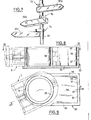
- FIG. 1 is a view in longitudinal section of the arm, along II of FIG. 2,
- FIG. 2 is a view in horizontal section along II-II of FIG. 1,
- FIG. 3 is a cross-sectional view along III-III of FIGS. 1 and 2,
- FIG. 4 is an end view along IV-IV of FIGS. 1 and 2,
- FIG. 5 is a perspective view of the open arm,
- FIG. 6 is a sectional view of the panel engaged on the post,
- FIG. 7 is a perspective view of a certain number of panels mounted on a post,
- FIG. 8 is a view in longitudinal section of the intermediate piece, along line VIII-VIII of FIG. 9,
- FIG. 9 is a view of the plane along line IX-IX of FIG. 8.
En référence aux figures 1 à 4, un bras 1 comprend deux coquilles 2a, 2b assemblées au moyen de deux vis 3a, 3b situées chacune à une extrémité du bras. Pour plus de clarté, ces vis ne sont représentées que sur la figure 4.Referring to Figures 1 to 4, an
A ces extrémités, la coquille 2a (seule représentée sur la figure 1, la coquille 2b étant supposée enlevée) présente des dents 4a formant découpe en grecque, entre lesquelles viennent s'emboîter des dents 4b de la coquille 2b (figure 4) disposées de façon similaire.At these ends, the
Les dents 4a et 4b sont percées de trous lisses 5, sauf, à chaque extrémité du bras 1, une dent extrême de la coquille 2a qui comporte un taraudage 6. Dans l'exemple décrit, ce taraudage est rapporté. Les vis 3a, 3b passent par les trous 5 et se vissent dans les taraudages 6.The
De la sorte, par démontage de l'une quelconque des deux vis, les deux coquilles peuvent pivoter autour de l'autre vis pour ouvrir le bras (figure 5).In this way, by dismantling any one of the two screws, the two shells can pivot around the other screw to open the arm (Figure 5).
Chaque coquille comporte un évidement sensiblement semi-cylindrique, respectivement 7a, 7b. Ces évidements sont disposés pour se faire vis-à-vis quand les coquilles sont assemblées (figure 2) et constituer une cavité cylindrique permettant le passage de tout poteau de signalisation, cylindrique ou polygonal, de diamètre usuel.Each shell has a substantially semi-cylindrical recess, respectively 7a, 7b. These recesses are arranged to face each other when the shells are assembled (Figure 2) and constitute a cylindrical cavity allowing the passage of any sign post, cylindrical or polygonal, of usual diameter.
Deux demi-cylindres 8a, 8b pratiqués dans des voiles 9a, 9b de chaque coquille constituent, une fois la coquille assemblée, un palier pour une portée lisse 11 d'une vis 12 munie d'un tronçon à six pans 13. La vis 12 est maintenue axialement par un circlip 14.Two half-
Cette vis coopère avec un taraudage 15 d'une pièce 16 montée coulissante dans les coquilles. A cette fin, les coquilles portent des glissières 17a, 17b profilées en T (figure 3). La pièce 16 comporte d'un côté une entaille en T pour coopérer avec la glissière 17b et, de l'autre côté, une large entaille 18 laissant passer les ailes de la glissière 17a.This screw cooperates with a
Enfin, une portée 19 en V, en matériau plastique, est fixée sur la pièce 16.Finally, a
On comprend que la manoeuvre du six pans 13 par une clef, à travers des fentes 21 ménagées dans les coquilles, permette de faire avancer la portée 19 jusqu'en 19a, au contact d'un poteau 22 logé dans la cavité.We understand that the operation of the
Vers l'extrémité du bras opposée aux évidements 7a, 7b, une pièce cylindrique 23 prend appui sur les coquilles par un épaulement 24. Cette pièce est traversée axialement par une vis 25 qui coopère avec un taraudage 26 d'un écrou 27 dont est solidaire un tenon 28. L'écrou 27 comporte une porté conique 29 en matériau plastique qui coopère avec une cavité conique 23a de la pièce 23.Towards the end of the arm opposite to the
Le tenon 28, qui fait saillie hors du bras du côté opposé à la tête de la vis 25, coopère avec une glissière 31 d'un panneau indicateur 32 (figure 6). Cette glissière est formée de deux ailes se faisant face et s'étendant sur une base horizontale (en position de service) du panneau.The
Il résulte de la structure décrite que le tenon 28 peut tourner autour de l'axe de la vis 25 et peut aussi glisser dans la glissière 31.It follows from the structure described that the
Pour monter un panneau sur un poteau, on enlève l'une des vis 3a ou 3b et l'on ouvre le bras. Dans cette opération, l'ensemble du tenon et de la pièce 23 échappe mais reste assemblé par le vis 25, et on le recueille. Par contre, la pièce 16 liée à la portée 19 en V n'échappe pas car elle est retenue accrochée à la coquille 2b par la glissière 17b en T.To mount a panel on a pole, remove one of the
On passe le bras ouvert autour du poteau 22 qui vient se loger dans les évidements 7a, 7b. Puis on replace l'ensemble du tenon 28 et de la pièce 23 et l'on ferme le bras et on le verrouille en replaçant la vis 3a. Enfin, en manoeuvrant la vis 12, on applique la portée 19 sur le poteau pour bloquer le bras après l'avoir orienté à la demande.We pass the open arm around the
Dans l'exemple décrit, les dimensions du bras et la course de la vis de blocage 12 sont telles que le bras puisse être fixé sur tout poteau d'un diamètre compris entre 70 et 120 mm, éventuellement polygonal.In the example described, the dimensions of the arm and the stroke of the locking
Ensuite, on engage la glissière 29 du panneau indicateur sur le tenon 28, la vis 25 étant supposée desserrée. On fait glisser le panneau sur le tenon jusqu'à atteindre la position désirée du point d'attache au bras, et on l'oriente définitivement. Enfin, on bloque la vis 25, ce qui a pour effet d'appliquer la glissière sur la face inférieure du bras et de bloquer la translation du panneau, et aussi de serrer la portée conique 29 pour bloquer sa rotation.Then, the
Suivant l'espace disponible autour du poteau, on pourra ouvrir le bras comme indiqué plus haut ou en enlevant la vis 3b et en faisant tourner les coquilles autour de la vis 3a.Depending on the space available around the post, you can open the arm as indicated above or by removing the
Grâce à l'invention, on peut monter sur un même poteau 22 un nombre quelconque de bras 1a, 1b, 1c portant chacun un panneau 32a, 32b, 32e (figure 7). Quel que soit l'environnement, l'orientation de chaque panneau est entièrement libre, disposant de deux angles de rotation arbitraires du bras autour du poteau et du panneau autour du bras. En outre, grâce à la glissière, aucune détermination préalable définitive au point de formation du panneau sur le bras n'est à prévoir.Thanks to the invention, it is possible to mount on the
Enfin, non seulement l'invention permet de fixer un panneau sur n'importe quel type de poteau, même initialement non prévu à cet effet, mais elle permet encore d'adjoindre un panneau supplémentaire sur un poteau qui en porte déjà un certain nombre. On peut même, à cet effet, déplacer les panneaux déjà en place, même si le poteau est d'un diamètre variable entre sa base et son sommet.Finally, not only does the invention make it possible to fix a panel on any type of pole, even initially not provided for this purpose, but it also makes it possible to add an additional panel to a pole which already carries a certain number thereof. One can even, for this purpose, move the panels already in place, even if the post is of a variable diameter between its base and its top.
On va maintenant décrire, en référence aux figures 8 et 9, une pièce intermédiaire 33 destinée à la fixation d'un panneau sur une paroi telle qu'un mur.We will now describe, with reference to Figures 8 and 9, an
Cette pièce est constituée par un fond 34 entouré sur trois côtés par deux parois 35 latérales et par une paroi transversale 36. Cette dernière est munie de trous 37 pour des boulons de fixation dans le mur.This part is constituted by a bottom 34 surrounded on three sides by two
Une partie avancée du fond 34, dégagée des parois latérales 35, porte un cylindre 38 d'un diamètre légèrement inférieur à celui de la cavité formée par les évidements 7a, 7b du bras 1.An advanced part of the bottom 34, released from the
Après avoir fixé la pièce 33 sur le mur par boulonnage, il suffit de coiffer le cylindre 38 par le bras 1 qui n'a pas besoin d'être ouvert. On bloque ensuite la portée 19 sur le cylindre.After fixing the
Les parois latérales 35 laissent un dégagement suffisant pour permettre une liberté importante d'orientation du bras, à laquelle s'ajoute la liberté de translation du panneau.The
Bien entendu, l'invention n'est pas limitée à l'exemple décrit mais couvre toute variante technologique à la portée de l'homme de l'art.Of course, the invention is not limited to the example described but covers any technological variant within the reach of ordinary skill in the art.
Claims (10)
Priority Applications (1)
| Application Number | Priority Date | Filing Date | Title |
|---|---|---|---|
| AT82401221T ATE22187T1 (en) | 1981-07-08 | 1982-06-30 | DEVICE FOR ATTACHING AN INFORMATION PANEL TO A CARRIER, SUCH PANEL AND RELATED INTERMEDIATE. |
Applications Claiming Priority (2)
| Application Number | Priority Date | Filing Date | Title |
|---|---|---|---|
| FR8113408A FR2509498A1 (en) | 1981-07-08 | 1981-07-08 | DEVICE FOR MOUNTING AN INDICATOR PANEL ON A SUPPORT, PANEL AND INTERMEDIATE PART RELATING THERETO |
| FR8113408 | 1981-07-08 |
Publications (2)
| Publication Number | Publication Date |
|---|---|
| EP0069653A1 true EP0069653A1 (en) | 1983-01-12 |
| EP0069653B1 EP0069653B1 (en) | 1986-09-10 |
Family
ID=9260342
Family Applications (1)
| Application Number | Title | Priority Date | Filing Date |
|---|---|---|---|
| EP82401221A Expired EP0069653B1 (en) | 1981-07-08 | 1982-06-30 | Device for mounting an information panel, panel and intermediate part belonging to it |
Country Status (4)
| Country | Link |
|---|---|
| EP (1) | EP0069653B1 (en) |
| AT (1) | ATE22187T1 (en) |
| DE (1) | DE3273174D1 (en) |
| FR (1) | FR2509498A1 (en) |
Cited By (4)
| Publication number | Priority date | Publication date | Assignee | Title |
|---|---|---|---|---|
| US4822348A (en) * | 1987-05-13 | 1989-04-18 | Donn Casey | Surgical clips |
| FR2650847A1 (en) * | 1989-08-09 | 1991-02-15 | Tech Nles Signalisation | Signalling assembly, especially for road arrowing (signposting) |
| US5002552A (en) * | 1987-11-10 | 1991-03-26 | Donn Casey | Surgical clip |
| WO1991012603A1 (en) * | 1990-02-19 | 1991-08-22 | Ole Schou Nielsen | Arrangement with at least one sign secured to at least one post |
Families Citing this family (1)
| Publication number | Priority date | Publication date | Assignee | Title |
|---|---|---|---|---|
| DE3739828C1 (en) * | 1987-11-24 | 1989-04-27 | Isaria Display Gmbh & Co Kg | Advertisement and information device |
Citations (5)
| Publication number | Priority date | Publication date | Assignee | Title |
|---|---|---|---|---|
| US1854145A (en) * | 1928-11-08 | 1932-04-12 | Anteck Forj Inc | Sign |
| GB643565A (en) * | 1947-12-02 | 1950-09-20 | Bernhard Volkery | Clamps |
| DE1188461B (en) * | 1963-04-01 | 1965-03-04 | Eugen Loeffler | License plate holder for motor vehicles |
| US3552702A (en) * | 1969-01-10 | 1971-01-05 | Heyer Inc | Sign holder |
| FR2346498A1 (en) * | 1976-04-02 | 1977-10-28 | Securite Signalisation | Sign-post of round hollow section - with radial fingers mounted at top on axially interfitting spigot sleeves secured by axial bolt |
-
1981
- 1981-07-08 FR FR8113408A patent/FR2509498A1/en active Granted
-
1982
- 1982-06-30 EP EP82401221A patent/EP0069653B1/en not_active Expired
- 1982-06-30 AT AT82401221T patent/ATE22187T1/en not_active IP Right Cessation
- 1982-06-30 DE DE8282401221T patent/DE3273174D1/en not_active Expired
Patent Citations (5)
| Publication number | Priority date | Publication date | Assignee | Title |
|---|---|---|---|---|
| US1854145A (en) * | 1928-11-08 | 1932-04-12 | Anteck Forj Inc | Sign |
| GB643565A (en) * | 1947-12-02 | 1950-09-20 | Bernhard Volkery | Clamps |
| DE1188461B (en) * | 1963-04-01 | 1965-03-04 | Eugen Loeffler | License plate holder for motor vehicles |
| US3552702A (en) * | 1969-01-10 | 1971-01-05 | Heyer Inc | Sign holder |
| FR2346498A1 (en) * | 1976-04-02 | 1977-10-28 | Securite Signalisation | Sign-post of round hollow section - with radial fingers mounted at top on axially interfitting spigot sleeves secured by axial bolt |
Non-Patent Citations (1)
| Title |
|---|
| TECHNOLOGICAL DIGESTS, vol. 8, no. 3, mars 1963, pages 59,60, O.E.C.D., Paris (FR); * |
Cited By (4)
| Publication number | Priority date | Publication date | Assignee | Title |
|---|---|---|---|---|
| US4822348A (en) * | 1987-05-13 | 1989-04-18 | Donn Casey | Surgical clips |
| US5002552A (en) * | 1987-11-10 | 1991-03-26 | Donn Casey | Surgical clip |
| FR2650847A1 (en) * | 1989-08-09 | 1991-02-15 | Tech Nles Signalisation | Signalling assembly, especially for road arrowing (signposting) |
| WO1991012603A1 (en) * | 1990-02-19 | 1991-08-22 | Ole Schou Nielsen | Arrangement with at least one sign secured to at least one post |
Also Published As
| Publication number | Publication date |
|---|---|
| ATE22187T1 (en) | 1986-09-15 |
| FR2509498A1 (en) | 1983-01-14 |
| EP0069653B1 (en) | 1986-09-10 |
| DE3273174D1 (en) | 1986-10-16 |
| FR2509498B1 (en) | 1984-10-26 |
Similar Documents
| Publication | Publication Date | Title |
|---|---|---|
| FR2705722A1 (en) | Device for operating locks by pushing or pulling. | |
| EP0757146B1 (en) | Locking device with at least one lock bolt, for a sliding frame | |
| FR2569626A1 (en) | LOCKING MECHANISM FOR A DECAPABLE VEHICLE | |
| WO2007063204A1 (en) | Locking device | |
| EP0069653A1 (en) | Device for mounting an information panel, panel and intermediate part belonging to it | |
| WO2007096540A1 (en) | Device for the hinged mounting of a window on a frameless door of a vehicle of the cabriolet or coupé type | |
| FR2719269A1 (en) | Assembly for the adjustable fixing in three dimensions of a lighting and / or signaling device of a motor vehicle. | |
| FR2476192A2 (en) | DOOR LOCK DEVICE | |
| FR2877979A1 (en) | Locking/unlocking device for e.g. hollow profiled frame, has support plate with inner cross bars moved from mounting position until to fixation position in which bars are deployed and tightened in support to fix support on front wall | |
| EP1607568A1 (en) | Support of a roller shaft and corresponding screen or solar protection | |
| FR2623553A1 (en) | Hinge with lateral engagement for a leaf and the like | |
| FR2567950A1 (en) | Hinge of the looped-pin type | |
| EP1059409B1 (en) | Drive gear for a lock follower | |
| FR2652374A1 (en) | HANDLE FOR A VEHICLE DOOR WITH A MOTOR. | |
| EP1244585B1 (en) | Method for mounting a motor vehicle hinged panel and device therefor | |
| EP0262998A1 (en) | Drilling device for wooden panels so as to assemble them by using dowels | |
| FR3096714A3 (en) | Comb type hinge for window and swing leaf doors | |
| FR2477624A1 (en) | CORNER BEARING FOR DOOR OR WINDOW LEAF | |
| FR2579658A1 (en) | Surface-mounted hinge for doors | |
| FR2538840A1 (en) | Adjustable stop-piece for a joinery leaf and particulary for windows, shutters or French windows | |
| FR2789416A1 (en) | PANEL FORMED FROM A GLASS PLATE, PROVIDED WITH AT LEAST ONE ASSEMBLY DEVICE TO A NEIGHBORING STRUCTURE | |
| FR2706938A1 (en) | Adjustable keeper for a motor-vehicle body lock | |
| FR2532355A1 (en) | System for protecting doors against break-in. | |
| FR2889236A1 (en) | ADJUSTABLE HINGE | |
| FR2662202A1 (en) | Device for attaching the control rods of bolts to the control levers of a lock |
Legal Events
| Date | Code | Title | Description |
|---|---|---|---|
| PUAI | Public reference made under article 153(3) epc to a published international application that has entered the european phase |
Free format text: ORIGINAL CODE: 0009012 |
|
| 17P | Request for examination filed |
Effective date: 19820703 |
|
| AK | Designated contracting states |
Designated state(s): AT BE CH DE GB IT LI LU NL SE |
|
| ITF | It: translation for a ep patent filed |
Owner name: BARZANO' E ZANARDO ROMA S.P.A. |
|
| GRAA | (expected) grant |
Free format text: ORIGINAL CODE: 0009210 |
|
| AK | Designated contracting states |
Kind code of ref document: B1 Designated state(s): AT BE CH DE GB IT LI LU NL SE |
|
| PG25 | Lapsed in a contracting state [announced via postgrant information from national office to epo] |
Ref country code: NL Effective date: 19860910 Ref country code: AT Effective date: 19860910 |
|
| REF | Corresponds to: |
Ref document number: 22187 Country of ref document: AT Date of ref document: 19860915 Kind code of ref document: T |
|
| PG25 | Lapsed in a contracting state [announced via postgrant information from national office to epo] |
Ref country code: SE Effective date: 19860930 |
|
| REF | Corresponds to: |
Ref document number: 3273174 Country of ref document: DE Date of ref document: 19861016 |
|
| NLV1 | Nl: lapsed or annulled due to failure to fulfill the requirements of art. 29p and 29m of the patents act | ||
| PG25 | Lapsed in a contracting state [announced via postgrant information from national office to epo] |
Ref country code: LI Effective date: 19870630 Ref country code: CH Effective date: 19870630 |
|
| PLBE | No opposition filed within time limit |
Free format text: ORIGINAL CODE: 0009261 |
|
| STAA | Information on the status of an ep patent application or granted ep patent |
Free format text: STATUS: NO OPPOSITION FILED WITHIN TIME LIMIT |
|
| 26N | No opposition filed | ||
| REG | Reference to a national code |
Ref country code: CH Ref legal event code: PL |
|
| ITTA | It: last paid annual fee | ||
| EPTA | Lu: last paid annual fee | ||
| REG | Reference to a national code |
Ref country code: GB Ref legal event code: 732E |
|
| PGFP | Annual fee paid to national office [announced via postgrant information from national office to epo] |
Ref country code: BE Payment date: 19970530 Year of fee payment: 16 |
|
| PGFP | Annual fee paid to national office [announced via postgrant information from national office to epo] |
Ref country code: GB Payment date: 19970624 Year of fee payment: 16 |
|
| PGFP | Annual fee paid to national office [announced via postgrant information from national office to epo] |
Ref country code: LU Payment date: 19970710 Year of fee payment: 16 |
|
| PGFP | Annual fee paid to national office [announced via postgrant information from national office to epo] |
Ref country code: DE Payment date: 19970814 Year of fee payment: 16 |
|
| PG25 | Lapsed in a contracting state [announced via postgrant information from national office to epo] |
Ref country code: LU Free format text: LAPSE BECAUSE OF NON-PAYMENT OF DUE FEES Effective date: 19980630 Ref country code: GB Free format text: LAPSE BECAUSE OF NON-PAYMENT OF DUE FEES Effective date: 19980630 Ref country code: BE Free format text: LAPSE BECAUSE OF NON-PAYMENT OF DUE FEES Effective date: 19980630 |
|
| BERE | Be: lapsed |
Owner name: ALLIBERT EQUIPEMENT Effective date: 19980630 |
|
| GBPC | Gb: european patent ceased through non-payment of renewal fee |
Effective date: 19980630 |
|
| PG25 | Lapsed in a contracting state [announced via postgrant information from national office to epo] |
Ref country code: DE Free format text: LAPSE BECAUSE OF NON-PAYMENT OF DUE FEES Effective date: 19990401 |