EP0070459A2 - Hand piece for laser knife - Google Patents
Hand piece for laser knife Download PDFInfo
- Publication number
- EP0070459A2 EP0070459A2 EP82106090A EP82106090A EP0070459A2 EP 0070459 A2 EP0070459 A2 EP 0070459A2 EP 82106090 A EP82106090 A EP 82106090A EP 82106090 A EP82106090 A EP 82106090A EP 0070459 A2 EP0070459 A2 EP 0070459A2
- Authority
- EP
- European Patent Office
- Prior art keywords
- holder
- hand piece
- end portion
- laser beam
- gripping end
- Prior art date
- Legal status (The legal status is an assumption and is not a legal conclusion. Google has not performed a legal analysis and makes no representation as to the accuracy of the status listed.)
- Withdrawn
Links
Images
Classifications
-
- A—HUMAN NECESSITIES
- A61—MEDICAL OR VETERINARY SCIENCE; HYGIENE
- A61B—DIAGNOSIS; SURGERY; IDENTIFICATION
- A61B18/00—Surgical instruments, devices or methods for transferring non-mechanical forms of energy to or from the body
- A61B18/18—Surgical instruments, devices or methods for transferring non-mechanical forms of energy to or from the body by applying electromagnetic radiation, e.g. microwaves
- A61B18/20—Surgical instruments, devices or methods for transferring non-mechanical forms of energy to or from the body by applying electromagnetic radiation, e.g. microwaves using laser
- A61B18/22—Surgical instruments, devices or methods for transferring non-mechanical forms of energy to or from the body by applying electromagnetic radiation, e.g. microwaves using laser the beam being directed along or through a flexible conduit, e.g. an optical fibre; Couplings or hand-pieces therefor
-
- A—HUMAN NECESSITIES
- A61—MEDICAL OR VETERINARY SCIENCE; HYGIENE
- A61B—DIAGNOSIS; SURGERY; IDENTIFICATION
- A61B17/00—Surgical instruments, devices or methods, e.g. tourniquets
- A61B17/30—Surgical pincettes without pivotal connections
-
- A—HUMAN NECESSITIES
- A61—MEDICAL OR VETERINARY SCIENCE; HYGIENE
- A61B—DIAGNOSIS; SURGERY; IDENTIFICATION
- A61B90/00—Instruments, implements or accessories specially adapted for surgery or diagnosis and not covered by any of the groups A61B1/00 - A61B50/00, e.g. for luxation treatment or for protecting wound edges
- A61B90/04—Protection of tissue around surgical sites against effects of non-mechanical surgery, e.g. laser surgery
- A61B2090/049—Protection of tissue around surgical sites against effects of non-mechanical surgery, e.g. laser surgery against light, e.g. laser
Definitions
- This invention relates to a hand piece for a laser knife.
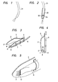
- a covered fiber 01 as shown in Fig. 1 is used directly.
- the front end portion of a fiber 01 is inserted into a straight tube 02, and a lens 04 is provided at the emergent end 03 of the fiber 01, so tht the laser beam emerging from the end 03 is applied to one point of the target part.
- the fiber 01 is not reinforced. Accordingly, the fiber is readily bent even by a small force.
- the fiber 01 is inserted into the straight tube 02. Accordingly, the flexibility of the fiber is limited, and the direction of irradiation is limited to the axial direction of the straight tube 02. Aecordingly, the range of applicability of the device is reduced by as much. Furthermore, when the power of the laser beam is high with respect to the thickness of the diseased tissue to be removed, or when it is necessary to apply the beam to the body part several times in order to remove the diseased tissue, the laser beam may pass through the diseased region to damage normal cells or tissues in the irradiation direction.
- a pair of tweezers held by one hand is normally used to grip the tissues to be removed, while a laser knife held by the other hand is used to sever the tissue; i.e., both hands are used.
- a laser knife held by the other hand is used to sever the tissue; i.e., both hands are used.
- an object of this invention is to provide a hand piece for a laser knife in which the above-described difficulties have been eliminated; i.e., wherein the laser beam is applied to only a desired area, and adjacent normal cells are not affected by the application of the laser beam.
- a first example of a laser knife hand piece according to the invention is in the form of a pair of tweezers as shown in Fig. 3.
- the hand piece 5 comprises a first holder 1 and a second holder 2, the rear end portions 4 of which are joined together in such a manner that the gripping end portions 3 thereof are elastically-closely spaced from each other.
- An optical fiber 6 is fixedly secured to the outer wall of the first holder with fasteners 7.
- the front end portion of the optical fiber 6 is inserted into a hole 9 cut in the first holder 1 in a manner such that the emergent end of the fiber 6 confronts the gripping end portion 3 of the second holder.2.
- the first example described above may be modified by replacing the first holder with a bent tube. After-an optical fiber is inserted into the bent tube, the tube is then coupled to the second holder in a manner such that the emergent end of the fiber and the gripping end portion of the second holder are elastically closely spaced.
- an optical fiber may be secured to a hand piece in the form of a clothespin. When necessary, the gripping portions of the hand piece are then manually operated to elastically grip the diseased tissues.
- the diseased region 10 is gripped and is pulled upwardly with the gripping end portion 3 of the second holder 2 and the emergent end 8 of the fiber 6. In this condition, the laser beam is then applied to sever the tissues 10 and remove the latter.
- the laser beam can be sufficiently intercepted by increased the area of the gripping end portion 3 of the second holder 2. However, if the gripping end portion 3 has a mirrored or smoothened surface, the laser beam is reflected thereby. Such reflection is of course hazardous. In order to prevent the same, it is necessary to roughen the surface of the gripping end portion 3 to thereby irregularly reflect the laser beam, or to subject the gripping end portion 3 to a surface treatment so that the gripping end portion 3 is suitably colored to absorb the laser beam to an extent.
- a second example of the laser knife hand piece according to the invention is as shown in Fig. 5.
- a water supplying tube 11 mounted on the second holder 2 has an opening near the gripping end portion 3 of the second holder 2, so that a liquid or physiological salt solution adapted to intercept the laser beam is applied to the surface of the gripping end portion 3 to which the laser beam is applied.
- the gripping end thus cooled, but also the laser beam is absorbed.
- the laser knife hand piece is excellent from a safety standpoint.
- the second example of the hand piece may be modified by providing a cooling medium circulating path in the hand piece itself.
- the second holder may be provided in the form of a pipe through which cooling solution flows, and the cooling solution may be discharged through small holes cut in the gripping end portion.
- the laser knife hand piece according to the invention is provided in the form of a pair of tweezers as described above. Therefore, the diseased part alone can readily be gripped with the hand piece, and accordingly it can be safely cut and removed.
- the gripping end portion which confronts the emergent end of the optical fiber, so that adjacent normal cells are protected from damage due to the laser beam.
Abstract
A hand piece for a laser knife includes a first holder with a gripping end portion and a second holder with a gripping end portion, and the holders are joined together in a manner such that the gripping end portions are elastically spaced in the manner of tweezers. A laser beam transmitting optical fiber is mounted on the gripping end portion of the first holder in a manner such that the emergent end of the optical fiber confronts the gripping end portion of the second holder, which is adapted to intercept the laser beam.
Description
- This invention relates to a hand piece for a laser knife. Heretofore, in a laser knife using an energy beam transmitting optical fiber (hereinafter referred to merely as "a fiber"), a covered
fiber 01 as shown in Fig. 1 is used directly. Alternatively, in such a laser knife, the front end portion of afiber 01 is inserted into astraight tube 02, and alens 04 is provided at theemergent end 03 of thefiber 01, so tht the laser beam emerging from theend 03 is applied to one point of the target part. In the former case, thefiber 01 is not reinforced. Accordingly, the fiber is readily bent even by a small force. Furthermore, since it is hazardous to hold the front end portion of thefiber 01, it is difficult to correctly apply the laser beam to the diseased tissue. On the other hand, in the latter case, thefiber 01 is inserted into thestraight tube 02. Accordingly, the flexibility of the fiber is limited, and the direction of irradiation is limited to the axial direction of thestraight tube 02. Aecordingly, the range of applicability of the device is reduced by as much. Furthermore, when the power of the laser beam is high with respect to the thickness of the diseased tissue to be removed, or when it is necessary to apply the beam to the body part several times in order to remove the diseased tissue, the laser beam may pass through the diseased region to damage normal cells or tissues in the irradiation direction. - In severing tissues, in order to facilitate the surgical operation, a pair of tweezers held by one hand is normally used to grip the tissues to be removed, while a laser knife held by the other hand is used to sever the tissue; i.e., both hands are used. In this case, it:-is difficult to correctly apply the laser beam to the tissues to be removed. If the hands shake even slightly, normal cells around the diseased area may be damaged.
- Accordingly, an object of this invention is to provide a hand piece for a laser knife in which the above-described difficulties have been eliminated; i.e., wherein the laser beam is applied to only a desired area, and adjacent normal cells are not affected by the application of the laser beam.
- The foregoing object and other objects as well as the specific features of the invention will become more apparent from the following detailed description when read in conjunction with the accompanying drawings, in which like parts are designated by like reference numerals.
-
- Figs. 1 and 2 are explanatory diagrams showing examples of a conventional laser knife hand piece;
- Fig. 3 is a perspective view showing a first example of a laser knife hand piece according to the invention;
- Fig. 4 is an explanatory diagram showing the use of the hand piece shown in Fig. 3; and,
- Fig. 5 is an enlarged perspective view showing a part of a second example of the laser knife hand piece according to the invention.
- A first example of a laser knife hand piece according to the invention is in the form of a pair of tweezers as shown in Fig. 3. The
hand piece 5 comprises afirst holder 1 and asecond holder 2, therear end portions 4 of which are joined together in such a manner that the grippingend portions 3 thereof are elastically-closely spaced from each other. Anoptical fiber 6 is fixedly secured to the outer wall of the first holder withfasteners 7. The front end portion of theoptical fiber 6 is inserted into ahole 9 cut in thefirst holder 1 in a manner such that the emergent end of thefiber 6 confronts thegripping end portion 3 of the second holder.2. - The first example described above may be modified by replacing the first holder with a bent tube. After-an optical fiber is inserted into the bent tube, the tube is then coupled to the second holder in a manner such that the emergent end of the fiber and the gripping end portion of the second holder are elastically closely spaced. As a further modification, an optical fiber may be secured to a hand piece in the form of a clothespin. When necessary, the gripping portions of the hand piece are then manually operated to elastically grip the diseased tissues.
- In cutting the diseased tissues with the hand piece described above, the
diseased region 10 is gripped and is pulled upwardly with the grippingend portion 3 of thesecond holder 2 and theemergent end 8 of thefiber 6. In this condition, the laser beam is then applied to sever thetissues 10 and remove the latter. - The laser beam can be sufficiently intercepted by increased the area of the
gripping end portion 3 of thesecond holder 2. However, if thegripping end portion 3 has a mirrored or smoothened surface, the laser beam is reflected thereby. Such reflection is of course hazardous. In order to prevent the same, it is necessary to roughen the surface of thegripping end portion 3 to thereby irregularly reflect the laser beam, or to subject thegripping end portion 3 to a surface treatment so that thegripping end portion 3 is suitably colored to absorb the laser beam to an extent. - A second example of the laser knife hand piece according to the invention is as shown in Fig. 5. In this example, a
water supplying tube 11 mounted on thesecond holder 2 has an opening near thegripping end portion 3 of thesecond holder 2, so that a liquid or physiological salt solution adapted to intercept the laser beam is applied to the surface of thegripping end portion 3 to which the laser beam is applied. In this case, not only is the gripping end thus cooled, but also the laser beam is absorbed. Thus, the laser knife hand piece is excellent from a safety standpoint. - The second example of the hand piece may be modified by providing a cooling medium circulating path in the hand piece itself. Also, the second holder may be provided in the form of a pipe through which cooling solution flows, and the cooling solution may be discharged through small holes cut in the gripping end portion.
- The laser knife hand piece according to the invention is provided in the form of a pair of tweezers as described above. Therefore, the diseased part alone can readily be gripped with the hand piece, and accordingly it can be safely cut and removed. When the laser beam passes through the diseased tissue, it is intercepted by the gripping end portion, which confronts the emergent end of the optical fiber, so that adjacent normal cells are protected from damage due to the laser beam.
Claims (8)
1. A hand piece for_a laser knife, comprising, a first holder having a gripping end portion, and a second holder having a confronting gripping end portion, said first and second holders being'joined in a manner such that said gripping end portions are elastically closely spaced, and
a laser beam transmitting optical fiber mounted on said gripping end portion of said first holder is a manner such that an emergent end of said optical fiber confronts said gripping end portion of said second holder, said second holder including means capable of intercepting said laser beam.
2. A hand piece as claimed in claim 1, said means for intercepting said laser beam comprising a surface treated area on said confronting gripping end portion for partially absorbing said laser beam.
3. A hand piece as claimed in claim 1, said means for intercepting said laser beam comprising a roughened area adapted to scatter said beam.
4. A hand piece as claimed in claim 1, said means for intercepting said laser beam comprising a conduit arranged on said second holder and including an outlet, and a laser beam absorbing fluid flowing in said conduit.
5. A hand piece as claimed in claim 4, said conduit comprising a circulating path for a cooling medium.
6. A hand piece as claimed in claim 1, further comprising cooling means including a circulating path for a cooling medium, and forming at least a part of said second holder.
7. A hand piece as claimed in claim 1, said first holder comprising a bent tube receiving said fiber.
8. A hand piece as claimed in claim 1, said gripping end portion of said first holder including said emergent end portion of said optical fiber.
Applications Claiming Priority (2)
| Application Number | Priority Date | Filing Date | Title |
|---|---|---|---|
| JP56108109A JPS5810039A (en) | 1981-07-13 | 1981-07-13 | Handpiece for laser knife |
| JP108109/81 | 1981-07-13 |
Publications (2)
| Publication Number | Publication Date |
|---|---|
| EP0070459A2 true EP0070459A2 (en) | 1983-01-26 |
| EP0070459A3 EP0070459A3 (en) | 1984-01-04 |
Family
ID=14476114
Family Applications (1)
| Application Number | Title | Priority Date | Filing Date |
|---|---|---|---|
| EP82106090A Withdrawn EP0070459A3 (en) | 1981-07-13 | 1982-07-07 | Hand piece for laser knife |
Country Status (4)
| Country | Link |
|---|---|
| EP (1) | EP0070459A3 (en) |
| JP (1) | JPS5810039A (en) |
| AU (1) | AU8595582A (en) |
| CA (1) | CA1190603A (en) |
Cited By (18)
| Publication number | Priority date | Publication date | Assignee | Title |
|---|---|---|---|---|
| DE3413520A1 (en) * | 1984-03-30 | 1985-10-31 | Vitalij Petrovič Moskau/Moskva Bašilov | Clamping device for clamping tissues during severing thereof with a laser beam |
| EP0205176A1 (en) * | 1985-06-12 | 1986-12-17 | Aesculap Ag | Surgical instrument |
| US4800877A (en) * | 1986-05-23 | 1989-01-31 | Laserscope | Laser output calibration tab |
| US4815461A (en) * | 1987-10-13 | 1989-03-28 | Rodriguez Michael A | Surgical laser backstop instrument |
| US4944738A (en) * | 1987-10-13 | 1990-07-31 | Rodriguez Michael A | Surgical laser backstop instrument |
| WO1990010420A1 (en) * | 1989-03-09 | 1990-09-20 | Applied Microsurgical Research Limited | Forceps |
| EP0441978A1 (en) * | 1989-09-01 | 1991-08-21 | S.L.T. Japan Co, Ltd. | Device for radiating laser beams |
| US5090908A (en) * | 1988-07-06 | 1992-02-25 | Teumim Stone Zvi | Laser apparatus for periodontal treatment |
| US5129896A (en) * | 1989-11-13 | 1992-07-14 | Hasson Harrith M | Holder to facilitate use of a laser in surgical procedures |
| US5147356A (en) * | 1991-04-16 | 1992-09-15 | Microsurge, Inc. | Surgical instrument |
| US5328488A (en) * | 1990-01-22 | 1994-07-12 | S.L.T. Japan Co., Ltd. | Laser light irradiation apparatus for medical treatment |
| US5342358A (en) * | 1993-01-12 | 1994-08-30 | S.L.T. Japan Co., Ltd. | Apparatus for operation by laser energy |
| US5672171A (en) * | 1994-06-30 | 1997-09-30 | American Medical Systems, Inc. | Apparatus and method for interstitial laser treatment |
| US5693041A (en) * | 1996-08-23 | 1997-12-02 | Eclipse Surgical Technologies, Inc. | Laser delivery means ring stabilization method and apparatus for surgical and other procedures |
| EP0910294A1 (en) * | 1996-07-01 | 1999-04-28 | University of Massachusetts | Fingertip-mounted minimally invasive surgical instruments and methods of use |
| EP0920280A1 (en) * | 1996-07-01 | 1999-06-09 | University of Massachusetts | Fingertip-mounted minimally invasive surgical instruments and methods of use |
| KR101430821B1 (en) | 2012-10-02 | 2014-08-14 | 강준규 | Electric Light Type Pinset Apparatus |
| CN105769291A (en) * | 2016-03-25 | 2016-07-20 | 何琴 | Detachable type luminous forceps |
Families Citing this family (1)
| Publication number | Priority date | Publication date | Assignee | Title |
|---|---|---|---|---|
| JPS59230547A (en) * | 1983-06-14 | 1984-12-25 | ヤ−マン株式会社 | Output holder for permanent dehairing device |
Citations (6)
| Publication number | Priority date | Publication date | Assignee | Title |
|---|---|---|---|---|
| DE2207387A1 (en) * | 1972-02-17 | 1973-08-23 | Messer Griesheim Gmbh | DEVICE FOR THE PROTECTION OF ORGANIC TISSUE |
| US3865113A (en) * | 1972-10-17 | 1975-02-11 | Laser Ind Ltd | Laser device particularly useful as surgical scalpel |
| DE2821264A1 (en) * | 1977-05-16 | 1978-11-23 | Olympus Optical Co | LASER SCALPEL |
| US4211229A (en) * | 1977-12-01 | 1980-07-08 | Richard Wolf Medical Instruments Corp. | Laser endoscope |
| FR2450660A1 (en) * | 1979-03-05 | 1980-10-03 | Fiat Auto Spa | APPARATUS FOR PROCESSING METAL WORKPIECES USING LASER RADIATION |
| EP0033958A1 (en) * | 1980-02-08 | 1981-08-19 | Sumitomo Electric Industries Limited | A laser knife |
-
1981
- 1981-07-13 JP JP56108109A patent/JPS5810039A/en active Pending
-
1982
- 1982-07-06 CA CA000406718A patent/CA1190603A/en not_active Expired
- 1982-07-07 EP EP82106090A patent/EP0070459A3/en not_active Withdrawn
- 1982-07-13 AU AU85955/82A patent/AU8595582A/en not_active Abandoned
Patent Citations (6)
| Publication number | Priority date | Publication date | Assignee | Title |
|---|---|---|---|---|
| DE2207387A1 (en) * | 1972-02-17 | 1973-08-23 | Messer Griesheim Gmbh | DEVICE FOR THE PROTECTION OF ORGANIC TISSUE |
| US3865113A (en) * | 1972-10-17 | 1975-02-11 | Laser Ind Ltd | Laser device particularly useful as surgical scalpel |
| DE2821264A1 (en) * | 1977-05-16 | 1978-11-23 | Olympus Optical Co | LASER SCALPEL |
| US4211229A (en) * | 1977-12-01 | 1980-07-08 | Richard Wolf Medical Instruments Corp. | Laser endoscope |
| FR2450660A1 (en) * | 1979-03-05 | 1980-10-03 | Fiat Auto Spa | APPARATUS FOR PROCESSING METAL WORKPIECES USING LASER RADIATION |
| EP0033958A1 (en) * | 1980-02-08 | 1981-08-19 | Sumitomo Electric Industries Limited | A laser knife |
Cited By (23)
| Publication number | Priority date | Publication date | Assignee | Title |
|---|---|---|---|---|
| DE3413520A1 (en) * | 1984-03-30 | 1985-10-31 | Vitalij Petrovič Moskau/Moskva Bašilov | Clamping device for clamping tissues during severing thereof with a laser beam |
| EP0205176A1 (en) * | 1985-06-12 | 1986-12-17 | Aesculap Ag | Surgical instrument |
| US4800877A (en) * | 1986-05-23 | 1989-01-31 | Laserscope | Laser output calibration tab |
| US4815461A (en) * | 1987-10-13 | 1989-03-28 | Rodriguez Michael A | Surgical laser backstop instrument |
| US4944738A (en) * | 1987-10-13 | 1990-07-31 | Rodriguez Michael A | Surgical laser backstop instrument |
| US5090908A (en) * | 1988-07-06 | 1992-02-25 | Teumim Stone Zvi | Laser apparatus for periodontal treatment |
| WO1990010420A1 (en) * | 1989-03-09 | 1990-09-20 | Applied Microsurgical Research Limited | Forceps |
| EP0441978A1 (en) * | 1989-09-01 | 1991-08-21 | S.L.T. Japan Co, Ltd. | Device for radiating laser beams |
| EP0441978A4 (en) * | 1989-09-01 | 1992-04-22 | S.L.T. Japan Co, Ltd. | Device for radiating laser beams |
| US5129896A (en) * | 1989-11-13 | 1992-07-14 | Hasson Harrith M | Holder to facilitate use of a laser in surgical procedures |
| US5470331A (en) * | 1990-01-22 | 1995-11-28 | S.L.T. Japan Co., Ltd. | Laser light irradiation apparatus for medical treatment |
| US5328488A (en) * | 1990-01-22 | 1994-07-12 | S.L.T. Japan Co., Ltd. | Laser light irradiation apparatus for medical treatment |
| US5147356A (en) * | 1991-04-16 | 1992-09-15 | Microsurge, Inc. | Surgical instrument |
| US5342358A (en) * | 1993-01-12 | 1994-08-30 | S.L.T. Japan Co., Ltd. | Apparatus for operation by laser energy |
| US5672171A (en) * | 1994-06-30 | 1997-09-30 | American Medical Systems, Inc. | Apparatus and method for interstitial laser treatment |
| EP0910294A1 (en) * | 1996-07-01 | 1999-04-28 | University of Massachusetts | Fingertip-mounted minimally invasive surgical instruments and methods of use |
| EP0920280A1 (en) * | 1996-07-01 | 1999-06-09 | University of Massachusetts | Fingertip-mounted minimally invasive surgical instruments and methods of use |
| EP0910294A4 (en) * | 1996-07-01 | 1999-08-11 | Univ Massachusetts | Fingertip-mounted minimally invasive surgical instruments and methods of use |
| EP0920280A4 (en) * | 1996-07-01 | 1999-09-01 | Univ Massachusetts | Fingertip-mounted minimally invasive surgical instruments and methods of use |
| EP1862134A3 (en) * | 1996-07-01 | 2008-02-20 | University of Massachusetts | Fingertip-mounted minimally invasive surgical instruments and methods of use |
| US5693041A (en) * | 1996-08-23 | 1997-12-02 | Eclipse Surgical Technologies, Inc. | Laser delivery means ring stabilization method and apparatus for surgical and other procedures |
| KR101430821B1 (en) | 2012-10-02 | 2014-08-14 | 강준규 | Electric Light Type Pinset Apparatus |
| CN105769291A (en) * | 2016-03-25 | 2016-07-20 | 何琴 | Detachable type luminous forceps |
Also Published As
| Publication number | Publication date |
|---|---|
| AU8595582A (en) | 1983-01-20 |
| CA1190603A (en) | 1985-07-16 |
| JPS5810039A (en) | 1983-01-20 |
| EP0070459A3 (en) | 1984-01-04 |
Similar Documents
| Publication | Publication Date | Title |
|---|---|---|
| EP0070459A2 (en) | Hand piece for laser knife | |
| EP0069389B1 (en) | Manipulator for laser knife | |
| US4517974A (en) | Disposable hand piece for surgical lasers | |
| AU8923382A (en) | Trocar | |
| JPH02213804A (en) | Laser light projector | |
| CA2129421A1 (en) | Surgical instrument | |
| ES8501575A1 (en) | Microsurgical laser. | |
| EP0746382A1 (en) | Device for laser application in fluid environment | |
| US20060271130A1 (en) | Transmission device for introducing light into an ear | |
| EP0230089A2 (en) | Laser instrument | |
| JP2794624B2 (en) | Laser probe | |
| JPS6326660B2 (en) | ||
| EP0380260A3 (en) | Ophthalmic measurement apparatus | |
| JPS62290451A (en) | Optical fiber cable | |
| EP0799603A2 (en) | Method of laser treatment for living tissue and target to be used therein | |
| Oka et al. | Composite-type optical fiberscope for laser surgery for twin-to-twin transfusion syndrome | |
| JPS5997109A (en) | Connector for optical fiber | |
| WO2020198049A1 (en) | Surgical device, laser surgery system, and methods of operation thereof | |
| JPH0240961Y2 (en) | ||
| JPS60108804A (en) | Optical fiber probe | |
| JPS6141676B2 (en) | ||
| JPH01136650A (en) | Contact type laser knife | |
| JPS62213748A (en) | Laser knife apparatus | |
| JPH02104347A (en) | Optical fiber cable | |
| JPH0221856A (en) | Laser probe |
Legal Events
| Date | Code | Title | Description |
|---|---|---|---|
| PUAI | Public reference made under article 153(3) epc to a published international application that has entered the european phase |
Free format text: ORIGINAL CODE: 0009012 |
|
| AK | Designated contracting states |
Designated state(s): DE FR GB SE |
|
| 17P | Request for examination filed |
Effective date: 19821230 |
|
| PUAL | Search report despatched |
Free format text: ORIGINAL CODE: 0009013 |
|
| AK | Designated contracting states |
Designated state(s): DE FR GB SE |
|
| STAA | Information on the status of an ep patent application or granted ep patent |
Free format text: STATUS: THE APPLICATION IS DEEMED TO BE WITHDRAWN |
|
| 18D | Application deemed to be withdrawn |
Effective date: 19860103 |
|
| RIN1 | Information on inventor provided before grant (corrected) |
Inventor name: TAKENAKA, SHINYAC/O SUMITOMO ELECTRIC Inventor name: SUNAGO, KATSUYOSHIC/O SUMITOMO ELECTRIC |