EP0073512A1 - Apparatus and method for controlling and mixing a liquid subjected to a centrifugal force - Google Patents
Apparatus and method for controlling and mixing a liquid subjected to a centrifugal force Download PDFInfo
- Publication number
- EP0073512A1 EP0073512A1 EP82107971A EP82107971A EP0073512A1 EP 0073512 A1 EP0073512 A1 EP 0073512A1 EP 82107971 A EP82107971 A EP 82107971A EP 82107971 A EP82107971 A EP 82107971A EP 0073512 A1 EP0073512 A1 EP 0073512A1
- Authority
- EP
- European Patent Office
- Prior art keywords
- liquid
- speed
- outlet channel
- storage chamber
- rotation
- Prior art date
- Legal status (The legal status is an assumption and is not a legal conclusion. Google has not performed a legal analysis and makes no representation as to the accuracy of the status listed.)
- Granted
Links
Images

Classifications
-
- B—PERFORMING OPERATIONS; TRANSPORTING
- B04—CENTRIFUGAL APPARATUS OR MACHINES FOR CARRYING-OUT PHYSICAL OR CHEMICAL PROCESSES
- B04B—CENTRIFUGES
- B04B5/00—Other centrifuges
- B04B5/04—Radial chamber apparatus for separating predominantly liquid mixtures, e.g. butyrometers
- B04B5/0407—Radial chamber apparatus for separating predominantly liquid mixtures, e.g. butyrometers for liquids contained in receptacles
-
- G—PHYSICS
- G01—MEASURING; TESTING
- G01N—INVESTIGATING OR ANALYSING MATERIALS BY DETERMINING THEIR CHEMICAL OR PHYSICAL PROPERTIES
- G01N21/00—Investigating or analysing materials by the use of optical means, i.e. using sub-millimetre waves, infrared, visible or ultraviolet light
- G01N21/01—Arrangements or apparatus for facilitating the optical investigation
- G01N21/03—Cuvette constructions
- G01N21/07—Centrifugal type cuvettes
-
- G—PHYSICS
- G01—MEASURING; TESTING
- G01N—INVESTIGATING OR ANALYSING MATERIALS BY DETERMINING THEIR CHEMICAL OR PHYSICAL PROPERTIES
- G01N35/00—Automatic analysis not limited to methods or materials provided for in any single one of groups G01N1/00 - G01N33/00; Handling materials therefor
- G01N2035/00465—Separating and mixing arrangements
- G01N2035/00495—Centrifuges
-
- Y—GENERAL TAGGING OF NEW TECHNOLOGICAL DEVELOPMENTS; GENERAL TAGGING OF CROSS-SECTIONAL TECHNOLOGIES SPANNING OVER SEVERAL SECTIONS OF THE IPC; TECHNICAL SUBJECTS COVERED BY FORMER USPC CROSS-REFERENCE ART COLLECTIONS [XRACs] AND DIGESTS
- Y10—TECHNICAL SUBJECTS COVERED BY FORMER USPC
- Y10T—TECHNICAL SUBJECTS COVERED BY FORMER US CLASSIFICATION
- Y10T436/00—Chemistry: analytical and immunological testing
- Y10T436/11—Automated chemical analysis
- Y10T436/111666—Utilizing a centrifuge or compartmented rotor
Abstract
Description
Die Erfindung betrifft eine Vorrichtung zum Steuern und Mischen einer dem Einfluß der Zentrifugalkraft in einem um eine Achse rotierenden Element, insbesondere dem Rotor eines Zentrifugalanalysators ausgesetzten Flüssigkeitsmenge, wobei die zu steuernde Flüssigkeitsmenge ein begrenztes Volumen hat, sowie ein Verfahren zum Betreiben einer derartigen Vorrichtung.The invention relates to a device for controlling and mixing an amount of liquid exposed to the influence of centrifugal force in an element rotating about an axis, in particular the rotor of a centrifugal analyzer, the amount of liquid to be controlled having a limited volume, and a method for operating such a device.
Die Erfindung ist insbesondere zur Verwendung in Zentrifugalanalysatoren geeignet, wie sie seit einer Reihe von Jahren für Zwecke der chemischen Analyse, insbesondere in der klinischen Chemie, gebräuchlich sind. Derartige Analysatoren zeichnen sich besonders durch ihren relativ einfachen mechanischen Aufbau und demzufolge große Zuverlässigkeit aus. Sie haben im allgemeinen kreissymetrisch aufgebaute Rotoren mit einer Mehrzahl von radial verlaufenden Strömungskanälen, die mehrere Kammern verbinden. Jeder Strömungskanal weist von innen nach außen üblicherweise einen muldenförmig ausgebildeten Reagenzraum, einen Probenraum und einen Meßraum auf, der bei den bekannten Einrichtungen als optische Küvette ausgebildet ist. Üblicherweise werden der Reagenzraum und der Probenraum bei stehendem Rotor mit flüssigem Reagenz beziehungsweise der zu untersuchenden flüssigen Probe (meist Serum oder Plasma des Blutes) gefüllt. Danach wird der Rotor in verhältnismäßig schnelle Umdrehung (größenordnungsmäßig 1ooo Umdrehungen/Minute) versetzt, so daß das Reagenz von der Zentrifugalkraft durch den Strömungskanal in die Probenkammer und Probe und Reagenz gemeinsam durch die Fortsetzung des Strömungskanals in die optische Küvette getrieben werden. Während der Rotation des Rotors wird dann die optische Absorption des Reaktionsgemisches in den verschiedenen Küvetten mit Hilfe geeigneter Detektoren und einer die Synchronisation des Rotorlaufs und der Auswerteeinrichtungen ermöglichenden elektronischen Schaltung gemessen. Ein besonderer Vorteil der Zentrifugalanalysatoren besteht hierbei darin, daß der Reaktionsverlauf in allen Küvetten des Rotors praktisch gleichzeitig verfolgt werden kann und dadurch eine besonders genaue Auswertung insbesondere dann möglich ist, wenn die Kinetik der Reaktion die gewünschte Aussage über einen bestimmten Bestandteil der Probenflüssigkeit gibt. Das Prinzip des Zentrifugalanalysators ist aus zahlreichen Publikationen bekannt, so daß hier nicht weiter darauf eingegangen werden soll.The invention is particularly suitable for use in centrifugal analyzers as have been in use for a number of years for chemical analysis purposes, particularly in clinical chemistry. Such analyzers are particularly characterized by their relatively simple mechanical structure and, consequently, great reliability. They generally have rotors of circular symmetry with a plurality of radially extending flow channels which connect a plurality of chambers. From the inside to the outside, each flow channel usually has a trough-shaped reagent chamber, a sample chamber and a measuring chamber, which in the known devices is designed as an optical cuvette. Usually, the reagent space and the sample space are filled with liquid reagent or the liquid sample to be examined (usually serum or plasma of the blood) when the rotor is stationary. Thereafter, the rotor is rotated at a relatively rapid rate (on the order of 100 revolutions / minute), so that the reagent is removed from the centrifugal force through the flow channel into the sample chamber and sample and reagent driven together into the optical cuvette by the continuation of the flow channel. During the rotation of the rotor, the optical absorption of the reaction mixture in the various cuvettes is then measured with the aid of suitable detectors and an electronic circuit which enables the rotor run and the evaluation devices to be synchronized. A particular advantage of centrifugal analyzers is that the course of the reaction in all cuvettes of the rotor can be followed practically simultaneously, making particularly precise evaluation possible, in particular if the kinetics of the reaction give the desired information about a specific component of the sample liquid. The principle of the centrifugal analyzer is known from numerous publications, so that it will not be discussed further here.
Ein Nachteil der bekannten Zentrifugalanalysatoren besteht darin, daß sie nur relativ einfache Reaktionsabläufe erlauben. Wie beschrieben, werden eine oder in Ausnahmefällen auch mehrere Reagenzflüssigkeiten in einem Arbeitsgang mit der Probe vermischt und durch Zentrifugalkraft in die Küvette transportiert. Die Reaktion muß deswegen notwendigerweise einstufig sein, das heißt es gibt insbesondere kein Möglichkeit, zunächst eine Vorreaktion mit einem ersten Reagenz ablaufen zu lassen und dann, gegebenenfalls nach einer entsprechenden Inkubationszeit, eine zweite Reaktion mit einem weiteren Reagenz durchzuführen. Derartige zweistufige Reaktionen sind aber insbesondere in der klinischen Analytik von erheblicher Bedeutung. In der DE-PS 2o o9 993 ist im Zusammenhang mit einer anderen Aufgabenstellung eine Einrichtung beschrieben, die eine Steuerung, das heißt ein Unterbrechen, gezieltes Freigeben und Umlenken einer Flüssigkeitsströmung in einer Einrichtung der eingangs erwähnten Art erlaubt. Bei dieser bekannten Vorrichtung sind im Strömungskanal der Flüssigkeit Hohlräume vorgesehen, die jeweils durch einen siphonartigen Kanal mit dem anschließenden Hohlraum verbunden sind. Derjenige Teil des Siphon, der der Rotationsachse am nächsten liegt, ist dieser näher als der Flüssigkeitsspiegel in dem Hohlraum bei der Rotation des Rotors. Dadurch wird zunächst nur der Hohlraum und der anschließende Teil des siphonförmigen Kanals mit Flüssigkeit gefüllt. Das Weiterströmen der Flüssigkeit aus dem Hohlraum in die sich an den Siphon anschließende Kammer wird dadurch bewerkstelligt, daß ein entsprechender Gasdruck an den Hohlraum angelegt wird, der die Flüssigkeit durch den Siphon treibt. Die Zuführung des notwendigen Druckgases zu dem Rotor kann nur in dessen Zentrum erfolgen und ist notwendigerweise aufwendig in der Konstruktion. Sie erfordert eine spezielle Rotorgestaltung, durch die der Konstruktion des Rotors in anderer Hinsicht unerwünschte Beschränkungen auferlegt werden.A disadvantage of the known centrifugal analyzers is that they only allow relatively simple reaction sequences. As described, one or, in exceptional cases, several reagent liquids are mixed with the sample in one operation and transported into the cuvette by centrifugal force. The reaction must therefore necessarily be in one stage, that is to say there is in particular no possibility of first allowing a preliminary reaction to take place with a first reagent and then, if appropriate after a corresponding incubation period, carrying out a second reaction with a further reagent. Such two-stage reactions are of considerable importance, especially in clinical analysis. In DE-PS 2o o9 993, in connection with another task, a device is described that controls, that is, interrupting, specifically releasing and deflecting a liquid keitsströmung allowed in a device of the type mentioned. In this known device cavities are provided in the flow channel of the liquid, each of which is connected to the adjoining cavity by a siphon-like channel. The part of the siphon that is closest to the axis of rotation is closer to it than the liquid level in the cavity during the rotation of the rotor. As a result, only the cavity and the subsequent part of the siphon-shaped channel are initially filled with liquid. The further flow of the liquid from the cavity into the chamber adjoining the siphon is accomplished in that a corresponding gas pressure is applied to the cavity, which drives the liquid through the siphon. The supply of the necessary compressed gas to the rotor can only take place in the center thereof and is necessarily complex in construction. It requires a special rotor design which imposes undesirable restrictions on the design of the rotor in other respects.
Aus der DE-OS 2o 22 o84 ist eine Vorrichtung bekannt, bei der ein Flüssigkeit, insbesondere eine Probenflüssigkeit, wie zum Beispiel Blut, zum Zwecke des Abzentrifugierens von festen Bestandteilen in entsprechende Kammern geschleudert wird, aus denen sie beim Anhalten des Rotors aufgrund der Schwerkraft in zentripetal schräg nach unten führende Kanäle abfließt. Diese Einrichtung hat einen erheblichen Platzbedarf und birgt, wollte man sie zum Steuern des Flüssigkeitsstroms verwenden, das Risiko, daß ein Teil der Flüssigkeit unkontrolliert durch die relativ großen Kanäle weiterströmt.From DE-OS
Ein anderes Problem der bekannten Zentrifugalanalysatoren bezieht sich auf die Durchmischung der Flüssigkeit. Es ist für die Analyse sehr wesentlich, daß Reagenz und Probe in kurzer Zeit und möglichst vollständig durchmischt werden, bevor sie in die Meßküvetten gelangen. Zur Erreichung dieses Zieles sind bereits eine Vielzahl von Verbesserungen an Zentrifugalanalysatoren vorgeschlagen worden, beispielsweise die Verwendung verschieden geformter Strömungshindernisse, die die Vermischung der sie durchströmenden Flüssigkeit verbessern sollen. Eine andere bekannte Vorrichtung zum Mischen von Probe und Reagenz in einem Zentrifugalanalysator ist der US-PS 3,795,451 zu entnehmen. Deren Rotor weist eine Probenkammer auf, die durch eine senkrechte Wand von der radial auswärts liegenden Meßküvette getrennt ist.Another problem with the known centrifugal analyzers relates to the mixing of the liquid. It is very important for the analysis that the reagent and sample are mixed as quickly and as completely as possible before they reach the measuring cuvettes. To achieve this goal, a large number of improvements to centrifugal analyzers have already been proposed, for example the use of differently shaped flow obstacles which are intended to improve the mixing of the liquid flowing through them. Another known device for mixing sample and reagent in a centrifugal analyzer can be found in US Pat. No. 3,795,451. The rotor has a sample chamber, which is separated from the radially outward measuring cell by a vertical wall.
Am oberen Ende der Trennwand ist ein Durchlaß von der Größe einer Kapillare vorgesehen. Radial innen voncbr Probenkammer liegt eine Reagenzkammer, wobei die Trennwand zwischen diesen schräg nach unten geneigt ist und an ihrem Unterende einen Durchlaß von der Abmessung einer Kapillare aufweist. Im Betrieb wird zunächst das Reagenz bei einer niedrigen Rotordrehzahl in die Probenkammer getrieben, die gleichzeitig als Mischkammer dient. Nach einer vorgegebenen Zeit wird die Drehzahl erhöht, wodurch die Reaktionslösung aus der Probenkammer in die Küvette getrieben wird. Mit einer derartigen Einrichtung, bei der die Verbindungskapillare zwischen Reagenzkammer und Probenkammer einerseits und zwischen Probenkammer und Küvette andererseits jeweils an der zentrifugal außen liegenden Wand der Kammern angeordnet ist und ausschließlich in Richtung der Zentrifugalkraft verläuft, wird zwar möglicherweise die Durchmischung von Reagenz und Probe in der Probenkammer verbessert, ein gleichzeitiges Steuern des Reaktionsablaufes in dem zuvor angesprochenen Sinne zur Erreichung einer möglichst vielfältigen Behandlung der Reaktionslösung, wird bei dieser vorbekannten Vorrichtung jedoch nicht erreicht (und in der Druckschrift auch nicht angestrebt).At the upper end of the partition there is a passage the size of a capillary. A reagent chamber is located radially inside of the sample chamber, the partition between them being inclined downwards and having a passage of the size of a capillary at its lower end. In operation, the reagent is first driven into the sample chamber at a low rotor speed, which also serves as a mixing chamber. After a predetermined time, the speed is increased, whereby the reaction solution is driven from the sample chamber into the cuvette. With such a device, in which the connecting capillary between the reagent chamber and sample chamber on the one hand and between the sample chamber and cuvette on the other hand is arranged on the centrifugal outer wall of the chambers and runs exclusively in the direction of the centrifugal force, the mixing of the reagent and sample in the Improved sample chamber, simultaneous control of the reaction process in the previously mentioned sense to achieve a treatment of the reaction solution that is as varied as possible, is not achieved with this previously known device (and is also not intended in the publication).
Der vorliegenden Erfindung liegt die Aufgabe zugrunde, ein Steuern, das heißt Umlenken, Unterbrechen und Freigeben einer volumenmäßig beschränkten Flüssigkeitsströmung und gleichzeitig ein Durchmischen der Flüssigkeit in einem rotierenden Element zu erreichen, wobei die entsprechende Vorrichtung zuverlässig und ohne bewegliche Teile arbeiten und auf engem Raum zu realisieren sein soll.The object of the present invention is to achieve control, that is to say deflecting, interrupting and releasing a volume-restricted liquid flow and at the same time mixing the liquid in a rotating element, the corresponding device working reliably and without moving parts and in a confined space should be realized.
Diese Aufgabe wird bei einer Vorrichtung der eingangs bezeichneten Art dadurch gelöst, daß im Strömungskanal für die Flüssigkeit eine nach radial außen geschlossene Staukammer vorgesehen ist, deren Rauminhalt größer ist als das maximale Flüssigkeitsvolumen und die so geformt ist, daß die Flüssigkeit bei einer Rotation des Elements mit einer hinreichend hohen ersten Drehzahl in ihr verbleibt und mit der Staukammer ein Auslaufkanal in Verbindung steht, der so geführt und angeordnet ist, daß mindestens ein Teil davon radial näher zur Rotationsachse als die Flüssigkeitsoberfläche während der Rotation mit der ersten Drehzahl liegt, dessen Wände aus einem von der Flüssigkeit benetzbaren Material bestehen und dessen Querschnitt so gestaltet ist, daß die Flüssigkeit bei einer zweiten Drehzahl, die kleiner ist als die erste Drehzahl, durch eine Grenzflächenkraft getrieben in den Auslaufkanal eindringt. Das entsprechende Verfahren ist dadurch gekennzeichnet, daß man die Flüssigkeit mit einer Drehzahl, die in einer Zentrifugalbeschleunigung resultiert, die größer ist als die Gravitationsbeschleunigung, in den Stauraum treibt und nach Ablauf der gewünschten Aufenthaltsdauer in dem Stauraum die Drehzahl soweit senkt, daß die Flüssigkeit den mit dem Stauraum verbundenen Auslaufkanal, durch Kapillarkraft getrieben, füllt.This object is achieved in a device of the type mentioned in that in the flow channel for the liquid a radially outwardly closed storage chamber is provided, the volume of which is greater than the maximum liquid volume and which is shaped such that the liquid remains in it when the element rotates at a sufficiently high first speed, and an outlet channel with the storage chamber Connection is made, which is guided and arranged so that at least a portion thereof is radially closer to the axis of rotation than the liquid surface during the rotation at the first speed, the walls of which consist of a material wettable by the liquid and the cross section of which is designed such that the Liquid at a second speed, which is less than the first speed, penetrates into the outlet channel, driven by an interfacial force. The corresponding method is characterized in that the liquid is driven into the storage space at a speed which results in a centrifugal acceleration which is greater than the gravitational acceleration and, after the desired duration of stay in the storage space, the speed is reduced to such an extent that the liquid causes the outlet channel connected to the storage space, driven by capillary force, fills.
Im Gegensatz zu der zuvor erwähnten bekannten Vorrichtung, zeichnet sich also die Erfindung dadurch aus, daß eine Staukammer vorgesehen ist, deren Auslaufkanal nicht unmittelbar radial nach außen mit der nächsten Kammer verbunden ist, sondern zumindest teilweise radial näher zur Rotationsachse liegt als die Flüssigkeitsoberfläche, die sich während der Rotation mit einer hinreichend hohen ersten Drehzahl in der Staukammer ausbildet. Gemäß dem erfindungsgemäßen Verfahren soll diese erste Drehzahl mindestens etwa so hoch sein, daß die daraus resultierende Zentrifugalbeschleunigung in der Staukammer etwa der Graviationsbeschleunigung entspricht. In diesem Fall erhält die Flüssigkeit einen nach unten und innen geneigten Meniskus, verbleibt aber während der Rotation mit der ersten Drehzahl in der Staukammer und gegebenenfalls, ähnlich wie bei der zuvor erwähnten siphonartigen Konstruktion, einem Teil des Auslaufkanals.In contrast to the known device mentioned above, the invention is characterized in that a stowage chamber is provided, the outlet channel of which is not directly connected radially outward to the next chamber, but is at least partially radially closer to the axis of rotation than the liquid surface forms during the rotation with a sufficiently high first speed in the storage chamber. According to the method according to the invention, this first speed should be at least approximately so high that the resulting centrifugal acceleration in the storage chamber is approximately the gravitational level acceleration corresponds. In this case, the liquid receives a meniscus which is inclined downwards and inwards, but remains in the stowage chamber during the rotation at the first speed and possibly, similar to the previously mentioned siphon-like construction, a part of the outlet channel.
Im Gegensatz zu der in der US-PS 3,795,451 beschriebenen Vorrichtung wird das Weiterströmen der Flüssigkeit nicht durch eine Erhöhung der Drehzahl, sondern durch eine Senkung der Drehzahl erreicht. Im Zusammenhang damit ist wichtig, daß der Auslaufkanal der Staukammer aus einem von der Flüssigkeit benetzbaren Material besteht. In diesem Fall sind die Adhäsionskräfte, die zwischen der Wand des Kanals und der Flüssigkeit wirken, größer als die Kohäsionskräfte zwischen den Flüssigkeitsteilchen und infolgedessen hat die Flüssigkeit das Bestreben, die sie begrenzende Wand zu benetzen. Man spricht in diesem Fall auch von einer positiven Grenzflächenenergie, die zu einer entsprechenden Grenzflächenkraft führt. Der Auslaufkanal ist in seinem. Querschnitt so gestaltet, daß diese Grenzflächenkraft oder Kapillarkraft die Flüssigkeit bei Abwesenheit anderer Kräfte und gegebenenfalls auch ohne Unterstützung durch die Schwerkraft in den Auslaufkanal ansaugt.In contrast to the device described in US Pat. No. 3,795,451, the further flow of the liquid is achieved not by increasing the speed, but by reducing the speed. In connection with this, it is important that the outlet channel of the storage chamber consists of a material that can be wetted by the liquid. In this case, the adhesive forces acting between the wall of the channel and the liquid are greater than the cohesive forces between the liquid particles and, as a result, the liquid tends to wet the wall delimiting it. In this case one speaks of a positive interfacial energy which leads to a corresponding interfacial force. The outlet channel is in his. Cross-section designed so that this interfacial force or capillary force sucks the liquid into the outlet channel in the absence of other forces and possibly also without the assistance of gravity.
Um eine Saugwirkung entfalten zu können, muß der Auslaufkanal kapillaraktiv gestaltet sein.In order to be able to develop a suction effect, the outlet channel must be designed to be capillary-active.
Besonders bevorzugt ist eine längliche, beispielsweise rechteckförmige Querschnittsgestaltung des Auslaufkanals, bei der die kleinere Dimension des Rechteckes so klein ist, daß eine Saugwirkung in dem gewünschten Ausmaß erreicht wird, während die längere Dimension des Querschnittsrechteckes so bemessen ist, daß insgesamt die für die gewünschte Strömung notwendige Querschnittsfläche resultiert.Particularly preferred is an elongated, for example rectangular cross-sectional design of the outlet channel, in which the smaller dimension of the rectangle is so small that a suction effect is achieved to the desired extent, while the longer dimension of the cross-sectional rectangle is dimensioned such that the total for the desired flow necessary cross-sectional area results.
Gemäß dem erfindungsgemäßen Verfahrensvorschlag tritt die Flüssigkeit, wie erwähnt, bei einer Senkung der Drehzahl in den Auslaufkanal ein und füllt diesen. Durch geeignete, im folgenden noch mehr im einzelnen beschriebene Maßnahmen, kann sie dann aus dem Auslaufkanal in einen entsprechenden Aufnahmeraum weitertransportiert werden, so daß die gewünschte Steuerung der Flüssigkeit allein durch eine entsprechende Variation der Drehzahl erreicht wird. Überraschenderweise führt die enge, kapillarförmige Gestaltung des Auslaufkanals nicht zu einer Sperrwirkung, die erst durch eine Erhöhung der Drehzahl überwunden werden müßte, sondern die Kapillarkraft läßt sich mit Hilfe der erfindungsgemäßen konstruktiven Maßnahmen vorteilhaft nutzen, um ein Weiterleiten der Flüssigkeit auch ohne Unterstützung anderer Kräfte, insbesondere der Schwerkraft oder eines entsprechenden Gasdruckes zu erreichen. Gleichzeitig werden mehrere in die Staukammer zugeführte flüssige Komponenten intensiv und schnell durchmischt. Es ist wohl als unerwartet anzusehen, daß eine derartige, insbesondere in einem Zentrifugalanalysator auf engem Raum unterzubringende und mit sehr kleinen Querschnittsdimensionen arbeitende Vorrichtung sehr zuverlässig funktioniert, wie praktische Erfahrungen mit der erfindungsgemäßen Vorrichtung zeigen.According to the proposed method according to the invention, as mentioned, the liquid enters and fills the outlet channel when the speed is reduced. By means of suitable measures, which are described in even more detail below, it can then be transported further from the outlet channel into a corresponding receiving space, so that the desired control of the liquid is achieved solely by a corresponding variation in the rotational speed. Surprisingly, the narrow, capillary design of the outlet channel does not lead to a blocking effect, which would have to be overcome only by increasing the speed, but the capillary force can be reduced with the aid of the design measures according to the invention use advantageously to achieve a forwarding of the liquid without the support of other forces, in particular gravity or a corresponding gas pressure. At the same time, several liquid components fed into the storage chamber are mixed intensively and quickly. It is probably to be regarded as unexpected that such a device, which can be accommodated in a narrow space in a centrifugal analyzer and works with very small cross-sectional dimensions, functions very reliably, as practical experience with the device according to the invention shows.
Die Erfindung wird im Folgenden anhand eines in der Zeichnung dargestellten Ausführungsbeispiels näher erläutert, wobei auch auf bevorzugte Ausführungsformen der Erfindung und die damit verbundenen Vorteile eingegangen wird.The invention is explained in more detail below on the basis of an exemplary embodiment shown in the drawing, preferred embodiments of the invention and the advantages associated therewith also being discussed.
Es zeigen:
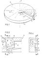
- Figur 1 eine schematische Darstellung des Rotors eines Zentrifugalanalysators mit einem darauf befindlichen Einsatzelement, das den Strömungskanal für die Flüssigkeit enthält.
- Figur 2a und 2b den Querschnitt von der Seite und die Aufsicht eines entsprechenden Einsatzelementes, das die erfindungsgemäße Vorrichtung aufweist.
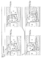
- Figur 3 eine Detailansicht einer erfindungsgemäßen Steuer-und Mischvorrichtung in einem Einsatzelement gemäß Figur 2.
- Figur 4 einen Querschnitt entlang der Linie IV - IV in Figur 3 und
- Figur 5 a bis d eine der Figur 3 entsprechende Darstellung, aus der der Funktionsablauf der erfindungsgemäßen Vorrichtung zu ersehen ist.
- Figure 1 is a schematic representation of the rotor of a centrifugal analyzer with an insert element located thereon, which contains the flow channel for the liquid.
- Figures 2a and 2b the cross section from the side and the supervision of a corresponding insert element having the device according to the invention.
- FIG. 3 shows a detailed view of a control and mixing device according to the invention in an insert element according to FIG. 2.
- 4 shows a cross section along the line IV - IV in Figure 3 and
- 5 a to d a representation corresponding to FIG. 3, from which the functional sequence of the device according to the invention can be seen.
Die Erfindung wird im Folgenden anhand eines speziell gestalteten Rotors eines Sentrifugalanalysators erläutert, der sich insbesondere dadurch auszeichnet, daß die Probenkammer und die Meßküvette sowie der beide verbindende Strömungskanal sich in einem von der Basis des Rotors getrennten Einsatzelement befinden, in dem die notwendigen Reagenzien auf einem Trägermaterial, beispielsweise in Form von Reagenzpapieren untergebracht sind. Es sei jedoch betont, daß die Erfindung auf jedes rotierende Element, in dem ein begrenztes Flüssigkeitsvolumen im beschriebenen Sinne gesteuert und gemischt werden soll, anwendbar ist. Dies gilt insbesondere für Rotoren von Zentrifugalanalysatoren unabhängig davon,ob sie einstückig oder aus mehreren Teilen hergestellt sind und ob die Reagenzien als Flüssigkeiten in den Rotor eingefüllt werden oder in fester Form darin vorhanden sind.The invention is explained below with the aid of a specially designed rotor of a centrifugal analyzer, which is characterized in particular by the fact that the sample chamber and the measuring cuvette and the flow channel connecting the two are located in an insert element which is separate from the base of the rotor and in which the necessary reagents are on a Carrier material, for example in the form of test papers are housed. However, it should be emphasized that the invention is applicable to any rotating element in which a limited volume of liquid is to be controlled and mixed as described. This applies in particular to the rotors of centrifugal analyzers regardless of whether they are made in one piece or from several parts and whether the reagents are filled into the rotor as liquids or are present in solid form.
In Figur 1 erkennt man einen in seiner Gesamtheit mit dem Bezugszeichen 1o bezeichneten Rotor eines Zentrifugalanalysators, der sich um eine Rotationsachse R drehen kann. Er ist stark vereinfacht dargestellt und besteht im wesentlichen aus einer Rotorbasis 12, auf dem mehrere Einsatzelemente 14 in verschiedenen Positionen befestigt werden können, wobei in der Figur der Übersichtlichkeit halber nur ein Einsatzelement 14 dargestellt und ein weiteres in strichpunktierten Linien angedeutet ist. Die Einsatzelemente 14 erstrecken sich im wesentlichen in radialer Richtung entlang den strichpunktierten Linien 16. Sie bestehen jeweils im wesentlichen aus einem Grundkörper 18 und einem Deckelteil 2o. In Figur 1 erkennt man die Probenkammeröffnung 22 und das Küvettenfenster 24.FIG. 1 shows a rotor of a centrifugal analyzer, designated in its entirety with the
Figur 2 zeigt Einzelheiten eines Einsatzelementes 14, das mit zwei erfindungsgemäßen Steuer- und Mischvorrichtungen 26 und 28 versehen ist, die im Folgenden einfachheitshalber als Mischventile bezeichnet werden. Der Strömungskanal für die Flüssigkeit in dem Einsatzelement geht aus von einer Probenkammer 3o durch einen Verbindungskanal 32 und 4 Reagenzfelder 33 bis 36 in die Staukammer 38 des ersten Mischventils 26. Aufgrund der im Folgenden näher beschriebenen Funktionsweise des Mischventils 26, gelangt die Flüssigkeit im Strömungskanal weiter durch den Auslaufkanal 4o in drei weitere Reaktionsfelder 41, 42 und 43. Von dort gelangt sie in die Staukammer 44 und, gezielt gesteuert aufgrund der Funktion des Mischventils 28, in den Auslaufkanal 46 und von dort in die Küvette 48, die aus dem eigentlichen Meßraum 5o und einem Küvettenvorraum 52 besteht. Sie ist nach oben und unten mit durchsichtigen Küvettenfenstern 54 versehen. Die beiden Mischventile 26 und 28, sowie der Küvettenvorraum 52 sind mit Entlüftungskanälen 55, 56 und 57 versehen. Das Einsatzelement 14 ist auf dem Rotor so eingebaut, daß es im wesentlichen radial von innen nach außen angeordnet ist, wobei die Probenkammer am nächsten zum Zentrum liegt.FIG. 2 shows details of an
Die"Reagenzfelder" 33 bis 36 und 41 bis 43 sind jeweils durch Über-58 strömkanäle miteinander verbunden und können verschiedene Funktionen erfüllen und in verschiedenerlei Weise gestaltet sein. Bevorzugt enthalten die Felder 33 bis 36 eines oder mehrere Papiere, die mit getrockneten Reagenzien versehen sind. Das Reagenzfeld 41 ist im Zusammenhang mit der Funktion des erfindungsgemäßen Mischventils 26 bevorzugt tiefer ausgebildet, wie insbesondere aus der Aufsicht auf das Einsatzelement gemäß Figur 2b zu ersehen ist. Je nach dem durchzuführenden Analyseverfahren kann es zweckmäßig sein, wenn dieses Reagenzfeld lediglich ein Saugvlies als kapillaraktiv wirkende Füllung enthält, das kein Reagenz trägt. In anderen Fällen wird aber auch dieses Vlies als Reagenzträger benutzt. Die Reagenzfelder 42 und 43 erfüllen wieder ähnliche Zwecke wie die Reagenzfelder 33 bis 36, enthalten aber Reagenzien für eine zweite Verfahrensstufe des mit dem Einsatzelement 14 durchzuführenden Analyseverfahren.The "reagent fields" 33 to 36 and 41 to 43 are each connected to one another by overflow channels and can perform different functions and be designed in different ways.
Im Betrieb wird eine in geeigneter Weise verdünnte zu analysierende Probe durch die Öffnung 22 in die Probenkammer 30 bei stehendem Rotor eingefüllt. Danach wird der Rotor in Drehung versetzt, so daß die Probenlösung aus der Probenkammer in das erste Reagenzfeld 33 und durch die weiteren Reagenzfelder 34 bis 36 in das erste Mischventil 26 gelangt. Beim Durchströmen der Reagenzfelder werden die in diesen enthaltenen Reagenzien aufgelöst und gelangen mit der Probenlösung in das Mischventil 26. Die Funktionsweise der in den Reagenzfeldern enthaltenen Reagenzträger und der Vorgang des Auflösens der Reagenzien ist in der DE-OS 30 44 385 näher beschrieben, auf die hier Bezug genommen wird. Aus dem ersten Satz Reagenzfeldern gelangt die Flüssigkeit, wie erwähnt, in die Staukammer 38 des Mischventils 26, wo sie solange verbleibt, wie eine hinreichend hohe Drehzahl des Rotors 1o aufrechterhalten wird. Diese Zeit bestimmt sich insbesondere nach der für die erste Verfahrensstufe notwendigen Inkubationszeit des Reaktionsgemisches.In operation, diluted sample to be analyzed through the
Aufbau und Funktion des Mischventils 26 werden im Folgenden anhand der Figuren 3 bis 5 näher beschrieben.The structure and function of the mixing
Figur 3 zeigt einen vergrößerten Ausschnitt der Querschnittsdarstellung gemäß Figur 2. Man erkennt das staukammerseitige Ende des Reagenzfeldes 36, das mit einer Trennwand 6o abgeschlossen ist, die auf der Seite des Reagenzfeldes schräg von radial einwärts unten nach radial auswärts oben geneigt ist. Oberhalb der Trennwand befindet sich die Einlauföffnung 62 der Staukammer 38.FIG. 3 shows an enlarged section of the cross-sectional view according to FIG. 2. The end of the
Die Staukammer 38 ist in der dargestellten Ausführungsform derart ausgebildet, daß sie in zentrifugaler Richtung, also in Figur 3 nach rechts vollständig geschlossen ist. Der radial äußerste Teil der Staukammer wird als Staukammerboden 64 bezeichnet.In the embodiment shown, the
Aus der Staukammer heraus führt der Auslaufkanal 4o,'der, wie aus dem Querschnitt nach Figur 4 deutlich zu ersehen ist, einen länglichen, im wesentlichen rechteckigen Querschnitt aufweist. Aus den Figuren und 4 ist deutlich zu ersehen, daß die eigentliche Staukammer 38 sehr viel tiefer (Distanz a) ausgebildet ist, das heißt in der Querschnittsdarstellung nach Figur 4 sehr viel breiter ist, als der Auslaufkanal 4o. Die Fläche 65 begrenzt den Auslaufkanal zusammen mit der Innenfläche 67 des Deckels 2o auf eine Breite b. Die Fläche 65 erstreckt sich mit ihrem Bereich 66 in die Staukammer 38. In den Figuren erkennt man die Fläche 70, die auf der radial äußeren Seite der Staukammer 38 durch den Übergang von der großen Tiefe a der Staukammer auf die geringe Tiefe b des Auslaufkanals 7o entsteht.The outlet duct 4o leads out of the storage chamber and, as can clearly be seen from the cross section according to FIG. 4, has an elongated, essentially rectangular cross section. It can be clearly seen from FIGS. 4 and 4 that the
In radialer Richtung betrachtet, also in der Zeichenebene von Figur 3, verläuft der Auslaufkanal 4o in einem ersten Abschnitt 72 nach radial innen und unten, also mit einer Richtungskomponente auf die Rotationsachse R zu. In dem zweiten Abschnitt 73 dagegen verläuft der Auslaufkanal mit einer Richtungskomponente radial von der Rotationsachse weg. Beide Abschnitte werden durch die Stauwand 74 getrennt. Der am nächsten zur Rotationsachse R liegende Teil der Stauwand 74 wird als Scheitelpunkt 76 bezeichnet. Der zweite Abschnitt des Auslaufkanals mündet in zentrifugaler Richtung in einen Aufnahmeraum, der bei dem hier dargestellten Mischventil 26 durch das Reagenzfeld 41 gebildet wird. Der Auslaufkanal 46 des Mischventils 28 mündet in den Küvettenvorraum 52 (Figur 2). Wesentlich ist, daß das Ende des Auslaufkanals, das heißt seine Mündung in den sich anschließenden Aufnahmeraum 41 beziehungsweise 52 weiter weg von der Rotationsachse liegt, als der radial äußerste Teil der Staukammer.Viewed in the radial direction, that is to say in the plane of the drawing in FIG. 3, the outlet channel 4o runs in a
In Figur 3 erkennt man schließlich noch einen Oberlaufkanal 78 in der oberen Wand 79der Staukammer 38, durch den bei der ersten Drehzahl ein einen bestimmten Grenzwert übersteigendes Flüssigkeitsvolumen abfließen kann. Dieser Überlaufkanal 78 ist nur dann notwendig, wenn die Staukammer 38 in an sich bekannter Weise gleichzeitig zur Begrenzung des aus dem Mischventil 26 weitergeleiteten Volumenstroms verwendet werden soll. Er ist daher in der Zeichnung gestrichelt dargestellt.Finally, FIG. 3 shows an
Die Funktionsweise der erfindungsgemäßen Steuer- und Mischvorrichtung wird im Folgenden anhand der in den Figuren 5a bis 5d dargestellten Verfahrensschritte näher beschrieben. Über den Figuren befindet sich ein Diagramm für den Drehzahlverlauf des Analysatorrotors, durch das das verwendete Drehzahlprogramm verdeutlicht wird.The mode of operation of the control and mixing device according to the invention is described in more detail below with reference to the method steps shown in FIGS. 5a to 5d. Above the figures there is a diagram for the speed curve of the analyzer rotor, by means of which the speed program used is illustrated.
Figur 5a zeigt das Stadium, bei dem die Flüssigkeit aus dem letzten Reagenzfeld 36 der ersten Stufe mit einer hinreichend hohen Drehzahl (im Beispiel 1000 Umdrehungen/Minute) herausgeschleudert wird und in die Staukammer 38 gelangt. Diese Drehzahl muß so hoch bemessen sein, daß die Flüssigkeit durch Zentrifugalkraft gegen den Staukammerboden 64 gedrückt wird. Je nach der Relation zwischen der auf die Flüssigkeit wirkenden Zentrifugalkraft einerseits und der Schwerkraft andererseits,bildet sich eine mehr oder weniger stark gekrümmte und geneigte Flüssigkeitsoberfläche 80. Die Drehzahl muß dabei so hoch bemessen sein, daß die Flüssigkeit im Kräftespiel zwischen der Zentrifugalkraft und der ihr in dem ersten Abschnitt 72 des Auslaufkanals entgegenwirkenden Kapillarkraft noch nicht weiter als maximal bis zu dem Scheitelpunkt 76 in den Auslaufkanal eindringt.FIG. 5 a shows the stage at which the liquid is thrown out of the
Figur 5b zeigt den Zustand während der Rotation mit der ersten Drehzahl. Man erkennt aus dieser Figur auch die Funktion des fakultativ vorgesehenen Oberlaufkanals 78, der sich an der Stelle befindet, an der die Flüssigkeitsoberfläche 8o bei der entsprechenden Drehzahl und dem gewünschten maximalen Volumen endet.Figure 5b shows the state during rotation at the first speed. The figure also shows the function of the optionally provided
Figur 5c zeigt das Auslaufen der Flüssigkeit durch den Auslaufkanal 4o. Wie aus dem Drehzahldiagramm über der Figur zu ersehen ist, wurde die Drehzahl erheblich vermindert, beispielweise auf ca. 5o Umdrehungen/Minute. Die Oberfläche 8o wird dadurch sehr viel weniger steil, weil die Zentrifugalkraft bei dieser geringen Drehzahl weniger stark ist als die Schwerkraft. Nun überwiegt in dem ersten Abschnitt 72 des Auslaufkanals 40, der im wesentlichen entgegen der Zentrifugalrichtung verläuft, die Kapillarkraft gegenüber der Zentrifugalkraft. Im zweiten Abschnitt 73 des Auslaufkanals wirken beide Kräfte in der gleichen Richtung, weil dieser eine Richtungskomponente in Zentrifugationsrichtung hat. Dadurch füllt sich, wie aus Figur 5c zu ersehen ist, der Auslaufkanal aufgrund der Kapillarkraft mit Flüssigkeit.FIG. 5c shows the liquid flowing out through the outlet channel 4o. As can be seen from the speed diagram above the figure, the speed has been considerably reduced, for example to about 50 revolutions / minute. This makes the
In Figur 5d ist ein Verfahrensstadium dargestellt, bei dem die Drehzahl langsam wieder erhöht wurde. Dies darf erst geschehen, wenn die Flüssigkeit im Auslaufkanal einen Punkt erreicht hat, der weiter weg von der Rotationsachse liegt als der Staukammerboden 64. Wenn in diesem Zustand ( wie beispielsweise in Figur 5c dargestellt) die Drehzahl langsam wieder erhöht wird, wirken auf die Flüssigkeitsteilchen in dem von der Staukammer 38 abgewandten Teil des Auslaufkanals 4o in dem Zentrifugations-Kraftfeld stärkere Kräfte als auf die im staukammerseitigen Teil des Auslaufkanals 4o befindlichen Wasserteilchen der Flüssigkeit. Dieser Effekt ist vergleichbar dem Wirkprinzip eines im chemischen Labor gebräuchlichen Saughebers im Schwerefeld. Bei der langsamen Beschleunigung des Rotors. wird dadurch die Flüssigkeit in den Aufnahmeraum 41 beziehungsweise 52 getrieben. In Figur 5d ist der Zustand dargestellt, bei dem die gesamte Flüssigkeit den Scheitelpunkt 76 gerade überwunden hat und wieder auf die volle erste Drehzahl beschleunigt werden kann.FIG. 5d shows a process stage in which the speed of rotation was slowly increased again. This may only happen when the liquid in the outlet channel has reached a point which is further away from the axis of rotation than the
Die Staukammer 38 kann in verschiedenerlei Weise gestaltet sein, wobei die für den Einzelfall sinnvollste Gestaltung durch Versuche bestimmt werden kann. Jedenfalls muß ihr Fassungsvermögen bei der ersten Drehzahl größer sein als das maximale Volumen der Flüssigkeit. Für den erfindungsgemäßen Effekt ist es günstig, wenn die Staukammer 38 eine im Verhältnis zum Volumen relativ kleine benetzte Oberfläche aufweist. Da sie nämlich aus praktischen Gründen bevorzugt aus dem gleichen Material wie der Auslaufkanal besteht, wird auch ihre Oberfläche von der Flüssigkeit benetzt. Dieser Effekt würde bei einer zu engen Gestaltung der Staukammer 38 der gewünschten Kapillarwirkung des Auslaufkanals 40 entgegenwirken.The
Der Auslaufkanal 40 selbst kann im Rahmen der vorliegenden Erfindung ebenfalls stark variiert werden. Die gewünschte Kapillarwirkung kann statt der in den Figuren dargestellten rechteckigen Querschnittsgestaltung auch durch eine entsprechende Faserfüllung oder beispielsweise durch ein Nutenprofil realisiert sein. In jedem Fall wird die Kraft, mit der die Flüssigkeit in den Kapillarspalt des Auslaufkanals 40 gesogen wird, einerseits durch die Benetzungseigenschaften des Materials und andererseits durch die charakteristische Breite b des Kapillarspaltes bestimmt. Im Einzelfall läßt sich die optimale Relation von Kapillarspaltquerschnitt, insbesondere der charakteristischen Breite b, verwendetem Material und Verlauf des Auslaufkanals 40 durch Versuche bestimmen.The
Die in den Figuren dargestellte Gestaltung des Auslaufkanals 40, bei der dieser in seinem durch den Bereich 66 der Fläche 65 definierten Bereich bereits während der Rotation mit der ersten Drehzahl zwangsweise benetzt wird, ist besonders bevorzugt, da die Zuverlässigkeit der erfindungsgemäßen Einrichtung dadurch erhöht wird.The design of the
Andererseits sind aber auch Anwendungsfälle denkbar, bei denen diese Maßnahme nicht notwendig oder zweckmäßig ist und der Auslaufkanal an einer Stelle in die Staukammer mündet, die bei Rotation mit der ersten Drehzahl nicht von der Flüssigkeit benetzt wird.On the other hand, applications are also conceivable in which this measure is not necessary or expedient and the outlet channel opens into the storage chamber at a point which is not wetted by the liquid when rotating at the first speed.
Bevorzugt ist der Aufnahmeraum 41 mit einer kapillaraktiven Füllung oder Gestaltung versehen. Das heißt es ist beispielsweise ein Vlies vorhanden, durch das die Flüssigkeit, wenn sie den Auslaufkanal vollständig gefüllt hat, in den Aufnahmeraum angesaugt wird. Bei dieser Ausführungsform der Erfindung ist es nicht notwendig, daß der Auslaufkanal 4o in seinem zweiten Abschnitt 73 in zentrifugaler Richtung verläuft. Er könnte beispielsweise auch von der Staukammer 38 aus unmittelbar senkrecht nach unten verlaufen, so daß beim Absenken der Drehzahl die Flüssigkeit nur noch durch Kapillarkraft und nicht, wie zuvor beschrieben, durch eine zusätzliche Zentrifugalwirkung in den Aufnahmeraum 41 gefördert wird.The receiving
In einer praktisch bewährten Ausführungsform der Erfindung wird Polymethylmetacrylat als Material für das Einsatzelement verwendet, das die notwendigen Benetzungseigenschaften gegenüber den in der klinischen Analytik üblichen Flüssigkeiten hat. Soll das Einsatzelement als Kunststoffspritzteil in großen Zahlen hergestellt werden, so ist insbesondere Polystyrol als Material geeignet.In a practically proven embodiment of the invention, polymethyl methacrylate is used as the material for the insert element, which has the necessary wetting properties compared to the liquids customary in clinical analysis. If the insert element is to be produced in large numbers as an injection molded plastic part, polystyrene is particularly suitable as the material.
Bei einer Ausführungsform der Erfindung, bei der die von dem Mischventil 26 aufzunehmende Flüssigkeitsmenge 4o bis 45 µl beträgt, hat sich in praktischen Versuchen ein Auslaufkanal mit einer charakteristischen Breite zwischen 0,2 und 1 mm, bevorzugt o,5 mm bewährt, wobei die Längsdimension des Querschnitts ca. 2 bis 4 mm betrug.In one embodiment of the invention, in which the amount of liquid to be taken up by the mixing
überraschenderweise erlauben die beschriebenen erfindungsgemäßen Mischventile 26 und 28 nicht nur das Steuern des Flüssigkeitsstroms insbesondere bei mehrstufigen analytischen Verfahren, sondern es wird zugleich eine sehr gute Durchmischung der Flüssigkeit erzielt. Dieser zunächst unerwartete Effekt der erfindungsgemäßen Konstruktion läßt sich wohl so erklären, daß sich in der Staukammer 38 zunächst Schichten verschiedener Konzentration bilden, die sich nur relativ langsam durchmischen. Beim Absenken der Drehzahl treten diese Schichten dann wohl im wesentlichen parallel in den Auslaufkanal 4o ein. Dort werden sie während des Auslaufens gemischt.Surprisingly, the described mixing
Nachdem die zu untersuchende Flüssigkeit in dem Einsatzelement 14 in der zuvor geschilderten Weise das Mischventil 26 durch Absenken und Wiedererhöhen der Drehzahl durchlaufen hat, gelangt sie,wie beschrieben, in das Reagenzfeld 41, das als Aufnahmekammer fungiert. Wie aus Figur 2b zu ersehen ist, ist dieses Reagenzfeld bevorzugt tiefer ausgeführt als die anderen Reagenzfelder, so daß das gesamte Flüssigkeitsvolumen in diesem Reagenzfeld aufgenommen werden kann-Von dort gelangt sie bei weiter erhöhter Drehzahl durch die gegebenenfalls mit entsprechenden Trockenreagenzien oder anderen in der DE-OS 3o 44 385 beschriebenen Einrichtungen gefüllten Reagensfelder 42 und 43 in das zweite Mischventil 28. In diesem Mischventil bleibt die Flüssigkeit, wie im ersten Mischventil 26, solange die erste höhere Drehzahl aufrecht erhalten wird. Wenn die gegebenenfalls gewünschte zweite Inkubationszeit abgelaufen ist, wird, genau wie zuvor beschrieben, die Drehzahl abgesenkt und nach Füllung der Auslaufkapillare 46 wieder erhöht, so daß die Flüssigkeit aufgrund der erfindungsgemäßen Wirkungsweise des Mischventils 28 in den Küvettenvorraum 52 und von dort in den Meßraum 5o eindringt. Das zweite Mischventil wird zweckmäßigerweise auch dann vorgesehen, wenn vom Reaktionsablauf her keine zweite Inkubationszeit notwendig ist, weil auch in diesem Falle die erfindungsgemäße Vorrichtung eine besonders intensive und schnelle Homogenisierung der in die Staukammer 44 zugeführten Flüssigkeit bewirkt.After the in the manner described above, the mixing
Claims (9)
im Strömungskanal (22, 32 - 36, 48) für die Flüssigkeit mindestens eine Staukammer (38) vorgesehen ist, deren Rauminhalt größer ist als das maximale Flüssigkeitsvolumen und die so geformt ist, daß die Flüssigkeit bei einer Rotation des Elementes (10) mit einer hinreichend hohen ersten Drehzahl in ihr verbleibt und
mit der Staukammer (38) ein Auslaufkanal (40) in Ver- bindung steht, der so geführt und angeordnet ist, daß mindestens ein Teil davon radial näher zur Rotationsachse (R) als die Flüssigkeitsoberfläche (80) während der Rotation mit der ersten Drehzahl liegt, dessen Wände aus einem von der Flüssigkeit benetzbaren Material bestehen und dessen Querschnitt so gestaltet ist, daß die Flüssigkeit bei einer zweiten Drehzahl, die kleiner ist als die erste Drehzahl, durch Grenzflächenkraft getrieben in den Auslaufkanal (40) eindringt.1. Device for controlling and mixing the influence of the centrifugal force in a rotating element about an axis, in particular the rotor (10) of a centrifugal analyzer exposed liquid flow, the amount of liquid to be controlled has a limited volume, characterized in that
in the flow channel (22, 32 - 36, 48) for the liquid at least one storage chamber (38) is provided, the volume of which is greater than the maximum liquid volume and which is shaped such that the liquid rotates when the element (10) rotates with a sufficiently high first speed remains in it and
with the storage chamber (38) an outlet channel (4 0) in V ER- bond, which is guided and arranged such that at least a portion thereof radially closer to the rotational axis (R) than the fluid surface (80) during the rotation of the first with the Speed is located, the walls of which consist of a material wettable by the liquid and the cross section of which is designed such that the liquid, driven by interfacial force, penetrates into the outlet channel (40) at a second speed, which is less than the first speed.
Priority Applications (1)
| Application Number | Priority Date | Filing Date | Title |
|---|---|---|---|
| AT82107971T ATE21171T1 (en) | 1981-09-01 | 1982-08-30 | DEVICE AND METHOD FOR CONTROLLING AND MIXING A FLOW OF LIQUID SUBJECT TO CENTRIFUGAL FORCE. |
Applications Claiming Priority (2)
| Application Number | Priority Date | Filing Date | Title |
|---|---|---|---|
| DE3134560 | 1981-09-01 | ||
| DE19813134560 DE3134560A1 (en) | 1981-09-01 | 1981-09-01 | DEVICE AND METHOD FOR CONTROLLING AND MIXING A LIQUID FLOW EXPOSED TO CENTRIFUGAL FORCE |
Publications (2)
| Publication Number | Publication Date |
|---|---|
| EP0073512A1 true EP0073512A1 (en) | 1983-03-09 |
| EP0073512B1 EP0073512B1 (en) | 1986-07-30 |
Family
ID=6140584
Family Applications (1)
| Application Number | Title | Priority Date | Filing Date |
|---|---|---|---|
| EP82107971A Expired EP0073512B1 (en) | 1981-09-01 | 1982-08-30 | Apparatus and method for controlling and mixing a liquid subjected to a centrifugal force |
Country Status (9)
| Country | Link |
|---|---|
| US (1) | US4557600A (en) |
| EP (1) | EP0073512B1 (en) |
| JP (1) | JPS5847260A (en) |
| AT (1) | ATE21171T1 (en) |
| AU (1) | AU550123B2 (en) |
| CA (1) | CA1190765A (en) |
| DE (2) | DE3134560A1 (en) |
| DK (1) | DK383582A (en) |
| ES (1) | ES515257A0 (en) |
Cited By (13)
| Publication number | Priority date | Publication date | Assignee | Title |
|---|---|---|---|---|
| US4462964A (en) * | 1982-01-14 | 1984-07-31 | Jean Guigan | Conditioning device for preparing multiple analyses |
| EP0132510A2 (en) * | 1983-04-25 | 1985-02-13 | Roche Diagnostics GmbH | Analytical apparatus for the photometrical determination of a parameter in a fluid |
| EP0160282A2 (en) * | 1984-05-03 | 1985-11-06 | Abbott Laboratories | Processor card for centrifuge |
| EP0167171A2 (en) * | 1984-07-06 | 1986-01-08 | Roche Diagnostics GmbH | Method and device for performing analytical determinations |
| EP0167175A2 (en) * | 1984-07-06 | 1986-01-08 | Roche Diagnostics GmbH | Device for washing a substance present in a field with a washing liquid in several washing steps and for transporting the washing fluid, emerging from said field, after the last washing step to a cuvette |
| FR2575293A1 (en) * | 1984-12-21 | 1986-06-27 | Inovelf Sa | DYNAMIC PIPETTING ROTOR FOR CENTRIFUGAL ANALYSIS DEVICE |
| GB2186081A (en) * | 1986-02-04 | 1987-08-05 | Orion Yhtymae Oy | Liquid analysis and analytical element |
| US4812411A (en) * | 1984-12-21 | 1989-03-14 | Jean Guigan | Method of performing medical analyses, and a conditioning strip and apparatus for performing the method |
| US4857274A (en) * | 1986-06-26 | 1989-08-15 | Kis Photo Industrie | Device for analyzing a liquid sample |
| US4902479A (en) * | 1983-11-07 | 1990-02-20 | Fisher Scientific Company | Centrifugal analyzer rotor |
| US4999304A (en) * | 1987-12-28 | 1991-03-12 | Miles Inc. | Dynamic braking centrifuge |
| US6783993B1 (en) | 1999-03-25 | 2004-08-31 | Alphahelix Ab | Homogenizing of small-volume mixtures by centrifugation and heating |
| EP2214027A1 (en) * | 2007-11-20 | 2010-08-04 | Toray Industries, Inc. | Liquid-feeding chip, and analyzing method |
Families Citing this family (31)
| Publication number | Priority date | Publication date | Assignee | Title |
|---|---|---|---|---|
| US4883763A (en) * | 1984-05-03 | 1989-11-28 | Abbott Laboratories | Sample processor card for centrifuge |
| JPS61139756A (en) * | 1984-12-12 | 1986-06-27 | Hitachi Koki Co Ltd | Centrifugal automatic reaction apparatus |
| FR2579755B1 (en) * | 1985-03-26 | 1988-04-15 | Guigan Jean | PROCESS FOR PERFORMING MEDICAL ANALYSIS OF A LIQUID SAMPLE USING DRY REAGENTS, AND DEVICE FOR CARRYING OUT THE METHOD |
| GB8514590D0 (en) * | 1985-06-10 | 1985-07-10 | Shandon Southern Prod | Centrifugation |
| US4695164A (en) * | 1985-09-24 | 1987-09-22 | Boehringer Mannheim Gmbh | Position detector and mount therefor for a centrifugal analyzer |
| US4762683A (en) * | 1986-09-16 | 1988-08-09 | E. I. Du Pont De Nemours And Company | Analysis device |
| US4775515A (en) * | 1986-11-18 | 1988-10-04 | Cottingham Hugh V | Agglutinographic slide |
| US4847205A (en) * | 1987-04-08 | 1989-07-11 | Martin Marietta Energy Systems, Inc. | Device and method for automated separation of a sample of whole blood into aliquots |
| US5173262A (en) * | 1987-07-17 | 1992-12-22 | Martin Marietta Energy Systems, Inc. | Rotor assembly and method for automatically processing liquids |
| US5242803A (en) * | 1987-07-17 | 1993-09-07 | Martin Marietta Energy Systems, Inc. | Rotor assembly and assay method |
| JPH0633765B2 (en) * | 1987-11-28 | 1994-05-02 | 株式会社三ツ葉電機製作所 | Magnet generator rotor and method of manufacturing the same |
| US5209904A (en) * | 1987-12-23 | 1993-05-11 | Abbott Laboratories | Agglutination reaction device utilizing selectively impregnated porous material |
| DE3814585A1 (en) * | 1988-04-29 | 1989-11-09 | Hoffmann La Roche | TEST ELEMENT FOR AGGLUTINATION EXAMINATIONS, METHOD FOR THE PRODUCTION THEREOF AND THE USE THEREOF |
| US5256376A (en) * | 1991-09-12 | 1993-10-26 | Medical Laboratory Automation, Inc. | Agglutination detection apparatus |
| EP1577010A3 (en) * | 1995-12-05 | 2005-11-16 | Tecan Trading AG | Microsystem platform and its use |
| AU1763401A (en) * | 1999-11-15 | 2001-05-30 | I-Stat Corporation | Apparatus and method for assaying coagulation in fluid samples |
| JP2005345160A (en) * | 2004-05-31 | 2005-12-15 | Advance Co Ltd | Biological information analyzing unit |
| JP4645211B2 (en) * | 2005-02-07 | 2011-03-09 | パナソニック株式会社 | HDL-cholesterol analysis disk and HDL-cholesterol analysis device |
| JP2006247492A (en) * | 2005-03-09 | 2006-09-21 | Ebara Corp | Solid-phase synthesis apparatus |
| JP4906362B2 (en) * | 2006-01-30 | 2012-03-28 | 株式会社日立ハイテクノロジーズ | Chemical analysis pretreatment equipment |
| WO2007105764A1 (en) * | 2006-03-16 | 2007-09-20 | Matsushita Electric Industrial Co., Ltd. | Disk for liquid sample analysis |
| JP4842796B2 (en) * | 2006-12-26 | 2011-12-21 | 株式会社日立エンジニアリング・アンド・サービス | Microorganism testing apparatus and microbe testing measuring chip |
| JP4614992B2 (en) * | 2007-07-27 | 2011-01-19 | パナソニック株式会社 | Analytical device, analytical apparatus and analytical method using the same |
| US8197774B2 (en) * | 2007-12-27 | 2012-06-12 | Rohm Co., Ltd. | Microchip |
| EP2239584B1 (en) * | 2008-01-28 | 2018-06-20 | Toray Industries, Inc. | Separating chip, and separating method |
| JP5504690B2 (en) * | 2008-05-15 | 2014-05-28 | 東レ株式会社 | Analysis chip |
| CN101981455B (en) * | 2008-07-17 | 2013-07-03 | 松下电器产业株式会社 | Analyzing device, and analyzing method using the analyzing device |
| US9535082B2 (en) | 2013-03-13 | 2017-01-03 | Abbott Laboratories | Methods and apparatus to agitate a liquid |
| US10058866B2 (en) | 2013-03-13 | 2018-08-28 | Abbott Laboratories | Methods and apparatus to mitigate bubble formation in a liquid |
| USD962471S1 (en) | 2013-03-13 | 2022-08-30 | Abbott Laboratories | Reagent container |
| USD978375S1 (en) | 2013-03-13 | 2023-02-14 | Abbott Laboratories | Reagent container |
Citations (6)
| Publication number | Priority date | Publication date | Assignee | Title |
|---|---|---|---|---|
| US4035156A (en) * | 1977-01-21 | 1977-07-12 | The United States Of America As Represented By The United States Energy Research And Development Administration | Filter type rotor for multistation photometer |
| DE2347465B2 (en) * | 1972-09-22 | 1977-07-21 | OPTICAL ANALYZER OF THE ROTATING CUVETTE | |
| DE2009993B2 (en) * | 1969-03-13 | 1978-05-24 | Atomic Energy Commission | Device for photometric analysis |
| DE2022084B2 (en) * | 1969-05-23 | 1979-03-08 | United States Atomic Energy Commission, Washington, D.C. | Rotary cuvette type photometric liquid analyzer |
| US4284602A (en) * | 1979-12-10 | 1981-08-18 | Immutron, Inc. | Integrated fluid manipulator |
| DE3044385A1 (en) * | 1980-11-25 | 1982-06-24 | Boehringer Mannheim Gmbh, 6800 Mannheim | METHOD FOR CARRYING OUT ANALYTICAL PROVISIONS AND ROTOR INSERT ELEMENT SUITABLE FOR THIS |
Family Cites Families (5)
| Publication number | Priority date | Publication date | Assignee | Title |
|---|---|---|---|---|
| US3555284A (en) * | 1968-12-18 | 1971-01-12 | Norman G Anderson | Multistation, single channel analytical photometer and method of use |
| DE2220016C3 (en) * | 1972-04-24 | 1980-06-12 | Henkel Kgaa, 4000 Duesseldorf | Reaction products of e - caprolactam with 13-propanediamines, process for their production and their use |
| US3795451A (en) * | 1973-04-24 | 1974-03-05 | Atomic Energy Commission | Rotor for fast analyzer of rotary cuvette type |
| US3829223A (en) * | 1973-07-20 | 1974-08-13 | Atomic Energy Commission | Mixing rotor for fast analyzer of rotary cuvette type with means for enhancing the mixing of sample and reagent liquids |
| US3873217A (en) * | 1973-07-24 | 1975-03-25 | Atomic Energy Commission | Simplified rotor for fast analyzer of rotary cuvette type |
-
1981
- 1981-09-01 DE DE19813134560 patent/DE3134560A1/en not_active Withdrawn
-
1982
- 1982-08-24 AU AU87556/82A patent/AU550123B2/en not_active Ceased
- 1982-08-26 ES ES515257A patent/ES515257A0/en active Granted
- 1982-08-27 DK DK383582A patent/DK383582A/en not_active Application Discontinuation
- 1982-08-30 JP JP57149355A patent/JPS5847260A/en active Granted
- 1982-08-30 AT AT82107971T patent/ATE21171T1/en not_active IP Right Cessation
- 1982-08-30 CA CA000410448A patent/CA1190765A/en not_active Expired
- 1982-08-30 DE DE8282107971T patent/DE3272314D1/en not_active Expired
- 1982-08-30 US US06/413,011 patent/US4557600A/en not_active Expired - Fee Related
- 1982-08-30 EP EP82107971A patent/EP0073512B1/en not_active Expired
Patent Citations (6)
| Publication number | Priority date | Publication date | Assignee | Title |
|---|---|---|---|---|
| DE2009993B2 (en) * | 1969-03-13 | 1978-05-24 | Atomic Energy Commission | Device for photometric analysis |
| DE2022084B2 (en) * | 1969-05-23 | 1979-03-08 | United States Atomic Energy Commission, Washington, D.C. | Rotary cuvette type photometric liquid analyzer |
| DE2347465B2 (en) * | 1972-09-22 | 1977-07-21 | OPTICAL ANALYZER OF THE ROTATING CUVETTE | |
| US4035156A (en) * | 1977-01-21 | 1977-07-12 | The United States Of America As Represented By The United States Energy Research And Development Administration | Filter type rotor for multistation photometer |
| US4284602A (en) * | 1979-12-10 | 1981-08-18 | Immutron, Inc. | Integrated fluid manipulator |
| DE3044385A1 (en) * | 1980-11-25 | 1982-06-24 | Boehringer Mannheim Gmbh, 6800 Mannheim | METHOD FOR CARRYING OUT ANALYTICAL PROVISIONS AND ROTOR INSERT ELEMENT SUITABLE FOR THIS |
Cited By (24)
| Publication number | Priority date | Publication date | Assignee | Title |
|---|---|---|---|---|
| US4462964A (en) * | 1982-01-14 | 1984-07-31 | Jean Guigan | Conditioning device for preparing multiple analyses |
| EP0132510A3 (en) * | 1983-04-25 | 1987-12-16 | Roche Diagnostics GmbH | Analytical apparatus for the photometrical determination of a parameter in a fluid |
| EP0132510A2 (en) * | 1983-04-25 | 1985-02-13 | Roche Diagnostics GmbH | Analytical apparatus for the photometrical determination of a parameter in a fluid |
| US4902479A (en) * | 1983-11-07 | 1990-02-20 | Fisher Scientific Company | Centrifugal analyzer rotor |
| EP0160282A2 (en) * | 1984-05-03 | 1985-11-06 | Abbott Laboratories | Processor card for centrifuge |
| EP0160282A3 (en) * | 1984-05-03 | 1986-03-05 | Abbott Laboratories | Processor card for centrifuge |
| US4915911A (en) * | 1984-07-06 | 1990-04-10 | Boehringer Mannheim Gmbh | Device for rinsing out a substance present in a zone |
| EP0167171A2 (en) * | 1984-07-06 | 1986-01-08 | Roche Diagnostics GmbH | Method and device for performing analytical determinations |
| EP0167175A3 (en) * | 1984-07-06 | 1987-09-30 | Boehringer Mannheim Gmbh | Device for washing a substance present in a field with a washing liquid in several washing steps and for transporting the washing fluid, emerging from said field, after the last washing step to a tray |
| EP0167171A3 (en) * | 1984-07-06 | 1988-06-22 | Boehringer Mannheim Gmbh | Method and device for performing analytical determinations |
| EP0167175A2 (en) * | 1984-07-06 | 1986-01-08 | Roche Diagnostics GmbH | Device for washing a substance present in a field with a washing liquid in several washing steps and for transporting the washing fluid, emerging from said field, after the last washing step to a cuvette |
| US4894204A (en) * | 1984-12-21 | 1990-01-16 | Inovelf | Rotor with dynamic pipeting for a centrifuge analysis device |
| EP0191257A1 (en) * | 1984-12-21 | 1986-08-20 | INOVELF, Société anonyme dite: | Dynamic pipetting rotor for a centrifugal-analysis device |
| FR2575293A1 (en) * | 1984-12-21 | 1986-06-27 | Inovelf Sa | DYNAMIC PIPETTING ROTOR FOR CENTRIFUGAL ANALYSIS DEVICE |
| US4812411A (en) * | 1984-12-21 | 1989-03-14 | Jean Guigan | Method of performing medical analyses, and a conditioning strip and apparatus for performing the method |
| GB2186081B (en) * | 1986-02-04 | 1990-10-17 | Orion Yhtymae Oy | A method for performing a liquid analysis and an analytical device for use in the method. |
| BE1001166A5 (en) * | 1986-02-04 | 1989-08-08 | Orion Yhtymae Oy | Analysis method for liquids and analysis element for use in the process. |
| FR2593920A1 (en) * | 1986-02-04 | 1987-08-07 | Orion Yhtymae Oy | LIQUID ANALYSIS METHOD AND ANALYSIS ELEMENT FOR USE IN THE PROCESS |
| GB2186081A (en) * | 1986-02-04 | 1987-08-05 | Orion Yhtymae Oy | Liquid analysis and analytical element |
| US4857274A (en) * | 1986-06-26 | 1989-08-15 | Kis Photo Industrie | Device for analyzing a liquid sample |
| US4999304A (en) * | 1987-12-28 | 1991-03-12 | Miles Inc. | Dynamic braking centrifuge |
| US6783993B1 (en) | 1999-03-25 | 2004-08-31 | Alphahelix Ab | Homogenizing of small-volume mixtures by centrifugation and heating |
| EP2214027A1 (en) * | 2007-11-20 | 2010-08-04 | Toray Industries, Inc. | Liquid-feeding chip, and analyzing method |
| EP2214027A4 (en) * | 2007-11-20 | 2015-06-03 | Toray Industries | Liquid-feeding chip, and analyzing method |
Also Published As
| Publication number | Publication date |
|---|---|
| ES8305223A1 (en) | 1983-05-01 |
| DK383582A (en) | 1983-03-02 |
| US4557600A (en) | 1985-12-10 |
| JPS5847260A (en) | 1983-03-18 |
| CA1190765A (en) | 1985-07-23 |
| AU8755682A (en) | 1983-03-10 |
| ATE21171T1 (en) | 1986-08-15 |
| JPH0224470B2 (en) | 1990-05-29 |
| DE3134560A1 (en) | 1983-03-17 |
| EP0073512B1 (en) | 1986-07-30 |
| ES515257A0 (en) | 1983-05-01 |
| AU550123B2 (en) | 1986-03-06 |
| DE3272314D1 (en) | 1986-09-04 |
Similar Documents
| Publication | Publication Date | Title |
|---|---|---|
| EP0073512B1 (en) | Apparatus and method for controlling and mixing a liquid subjected to a centrifugal force | |
| EP2072131B1 (en) | Microfluid element for mixing a fluid into a reagent | |
| DE2260292C2 (en) | Photometric analyzer | |
| DE4293865B4 (en) | Improved cytocentrifugation device, apparatus and process | |
| DE69730893T2 (en) | pretreatment device | |
| EP0073513B1 (en) | Method of carrying out an analytical determination, and suitable means therefor | |
| EP1685900B1 (en) | Use of a device for analysing a liquid sample | |
| EP0052770B1 (en) | Rotor unit with removable segments for a centrifugal analyzer | |
| EP0039825A1 (en) | Cuvette rotor for analyzer and method of operation of said cuvette rotor | |
| EP2632591B1 (en) | Microfluidic element for analysis of a sample liquid | |
| EP1761757A1 (en) | Device for collecting blood and separating blood constituents, method for separating blood constituents and use of said device | |
| EP3592463B1 (en) | Method for centrifugo-pneumatic switching of liquid | |
| EP0052769A1 (en) | Method for analytical assays and rotor element for carrying out the method | |
| DE2458384A1 (en) | MULTI-SAMPLE ROTOR ARRANGEMENT FOR THE PRODUCTION OF BLOOD FRACTIONS | |
| EP0371003A2 (en) | Device for the analytical determination of components in a body fluid | |
| DE3151291A1 (en) | DEVICE FOR ANALYZING BIOLOGICAL FLUIDS | |
| DE2336619C2 (en) | Photometric analyzer | |
| EP0668496A2 (en) | Cuvette for performing optical measurements | |
| DE2432498C3 (en) | Analysis centrifuge | |
| EP0405162B1 (en) | Cellrotor | |
| DE102006025477B4 (en) | Cuvette and process for its preparation | |
| DE3333674C2 (en) | Clear slide for microscopic examination of liquid samples | |
| DE2117423C3 (en) | ||
| EP1533035A1 (en) | Sample carrier | |
| DE19857215A1 (en) | Multi-cuvette rotor |
Legal Events
| Date | Code | Title | Description |
|---|---|---|---|
| PUAI | Public reference made under article 153(3) epc to a published international application that has entered the european phase |
Free format text: ORIGINAL CODE: 0009012 |
|
| 17P | Request for examination filed |
Effective date: 19820830 |
|
| AK | Designated contracting states |
Designated state(s): AT BE CH DE FR GB IT LI LU NL SE |
|
| GRAA | (expected) grant |
Free format text: ORIGINAL CODE: 0009210 |
|
| AK | Designated contracting states |
Kind code of ref document: B1 Designated state(s): AT BE CH DE FR GB IT LI LU NL SE |
|
| REF | Corresponds to: |
Ref document number: 21171 Country of ref document: AT Date of ref document: 19860815 Kind code of ref document: T |
|
| PG25 | Lapsed in a contracting state [announced via postgrant information from national office to epo] |
Ref country code: LU Free format text: LAPSE BECAUSE OF NON-PAYMENT OF DUE FEES Effective date: 19860831 |
|
| PGFP | Annual fee paid to national office [announced via postgrant information from national office to epo] |
Ref country code: NL Payment date: 19860831 Year of fee payment: 5 |
|
| REF | Corresponds to: |
Ref document number: 3272314 Country of ref document: DE Date of ref document: 19860904 |
|
| ITF | It: translation for a ep patent filed |
Owner name: ING. C. GREGORJ S.P.A. |
|
| ET | Fr: translation filed | ||
| PLBE | No opposition filed within time limit |
Free format text: ORIGINAL CODE: 0009261 |
|
| STAA | Information on the status of an ep patent application or granted ep patent |
Free format text: STATUS: NO OPPOSITION FILED WITHIN TIME LIMIT |
|
| 26N | No opposition filed | ||
| PG25 | Lapsed in a contracting state [announced via postgrant information from national office to epo] |
Ref country code: SE Effective date: 19870831 |
|
| BERE | Be: lapsed |
Owner name: BOEHRINGER MANNHEIM G.M.B.H. Effective date: 19870831 |
|
| PG25 | Lapsed in a contracting state [announced via postgrant information from national office to epo] |
Ref country code: NL Effective date: 19880301 |
|
| NLV4 | Nl: lapsed or anulled due to non-payment of the annual fee | ||
| PG25 | Lapsed in a contracting state [announced via postgrant information from national office to epo] |
Ref country code: BE Effective date: 19890831 |
|
| ITTA | It: last paid annual fee | ||
| EUG | Se: european patent has lapsed |
Ref document number: 82107971.2 Effective date: 19880711 |
|
| PGFP | Annual fee paid to national office [announced via postgrant information from national office to epo] |
Ref country code: FR Payment date: 19950809 Year of fee payment: 14 |
|
| PGFP | Annual fee paid to national office [announced via postgrant information from national office to epo] |
Ref country code: AT Payment date: 19950811 Year of fee payment: 14 |
|
| PGFP | Annual fee paid to national office [announced via postgrant information from national office to epo] |
Ref country code: GB Payment date: 19950821 Year of fee payment: 14 |
|
| PGFP | Annual fee paid to national office [announced via postgrant information from national office to epo] |
Ref country code: CH Payment date: 19950828 Year of fee payment: 14 |
|
| PGFP | Annual fee paid to national office [announced via postgrant information from national office to epo] |
Ref country code: DE Payment date: 19950829 Year of fee payment: 14 |
|
| PG25 | Lapsed in a contracting state [announced via postgrant information from national office to epo] |
Ref country code: GB Effective date: 19960830 Ref country code: AT Effective date: 19960830 |
|
| PG25 | Lapsed in a contracting state [announced via postgrant information from national office to epo] |
Ref country code: LI Effective date: 19960831 Ref country code: CH Effective date: 19960831 |
|
| REG | Reference to a national code |
Ref country code: CH Ref legal event code: PL |
|
| GBPC | Gb: european patent ceased through non-payment of renewal fee |
Effective date: 19960830 |
|
| PG25 | Lapsed in a contracting state [announced via postgrant information from national office to epo] |
Ref country code: FR Effective date: 19970430 |
|
| PG25 | Lapsed in a contracting state [announced via postgrant information from national office to epo] |
Ref country code: DE Effective date: 19970501 |
|
| REG | Reference to a national code |
Ref country code: FR Ref legal event code: ST |