EP0074744A2 - Stapler - Google Patents
Stapler Download PDFInfo
- Publication number
- EP0074744A2 EP0074744A2 EP82304545A EP82304545A EP0074744A2 EP 0074744 A2 EP0074744 A2 EP 0074744A2 EP 82304545 A EP82304545 A EP 82304545A EP 82304545 A EP82304545 A EP 82304545A EP 0074744 A2 EP0074744 A2 EP 0074744A2
- Authority
- EP
- European Patent Office
- Prior art keywords
- ram
- staple
- stapler
- anvil
- adjacent
- Prior art date
- Legal status (The legal status is an assumption and is not a legal conclusion. Google has not performed a legal analysis and makes no representation as to the accuracy of the status listed.)
- Granted
Links
Images

Classifications
-
- A—HUMAN NECESSITIES
- A61—MEDICAL OR VETERINARY SCIENCE; HYGIENE
- A61B—DIAGNOSIS; SURGERY; IDENTIFICATION
- A61B17/00—Surgical instruments, devices or methods, e.g. tourniquets
- A61B17/068—Surgical staplers, e.g. containing multiple staples or clamps
- A61B17/0682—Surgical staplers, e.g. containing multiple staples or clamps for applying U-shaped staples or clamps, e.g. without a forming anvil
- A61B17/0684—Surgical staplers, e.g. containing multiple staples or clamps for applying U-shaped staples or clamps, e.g. without a forming anvil having a forming anvil staying above the tissue during stapling
Definitions
- This invention relates to staplers of the type adapted to join living tissue.
- Staplers adapted to join living tissue are well known.
- the earliest known type of staplers for such use were designed to be reusable and included high quality castings and machined parts of easily cleanable and sterilizable materials such as stainless steel (see, for example, the staplers described in U.S. Patents Nos. 3,643,851, 3,819,100 and 3,873,016).
- Such staplers typically are sterilized before each use in sterilizing equipment located at the facility (e.g., a hospital) in which they are used.
- the high cost of disassembling, cleaning and sterilizing such staplers before each use makes their use uneconomical where only a few staples are to be applied to a patient.
- the time needed for the sterilization procedure between successive uses of such staplers further restricts their use where a series of patients may each need the application of only a few staples, such as may occur in a hospital emergency room.
- staplers for joining living tissue are designed to be disposable (see for example the staplers described in U.S. Patents Nos. 4,109,844, 4,202,480 and 4,256,251).
- Such disposable staplers are made of relatively inexpensive parts such as plastic moldings and metal stampings that are sterilized during manufacturing and are packaged so that they remain sterilized until they are used.
- Such staplers are intended for use on only one patient, however.
- That stapler comprises an elongate body having a guide surface adjacent a front end of the body, and an anvil transversely centered at the front end projecting at a right angle to the guide surface.
- Means are provided for feeding staples onto the guide surface with points of the staples adjacent the front end of the body, and a ram is mounted on the body for movement from an open position to a closed position to cause the ram to bend a staple on the guide surface closed around the anvil.
- the ram can be manually moved by a pair of toggle joint linkages attached between a rear end of the body and the ram.
- the toggle joint linkages are opposed and project away from opposite sides of the body when the ram is in its retracted position so that pressing the toggle joint linkages toward each other in a direction transverse to the guideway will move the ram from its open to its closed position.
- An improved version of that stapler has been sold for over 12 months under the trademark "Precise” by Minnesota Mining and Manufacturing Company of St. Paul, Minnesota, and has been found to be an effective mechanism for applying staples. Like the other disposable staplers on the market, however, its mechanism is too complex to make the stapler economical to apply only a few staples.
- the present invention provides an effective, inexpensive, disposable-type stapler that is economical to use when only a small number of staples (e.g., 1 to 10) are to be applied to a patient.
- a stapler which, like the stapler described in U.S. Patent No. 4,202,480, comprises an elongate body, a guide surface adjacent a front end of the stapler, and an anvil transversely centered at its front end projecting at a right angle to the guide surface. Means are provided for positioning a staple on the body adjacent the anvil with a side surface of the staple along the guide surface and the points of the staple adjacent the front end of the body.
- a ram having an end surface adapted to engage the edge surface of the staple opposite its points is mounted on the body for movement from an open position with the end surface of the ram spaced from the anvil to afford space for the open staple therebetween, to a closed position to cause the end surface of the ram to engage and bend the staple closed around the anvil.
- a toggle joint linkage is attached between the rear end of the body and the ram so that the toggle joint linkage projects from the body in the open position of the ram and is manually movable toward the body to move the ram to its closed position.
- the stapler according to the present invention has a novel greatly simplified design that includes only a single toggle joint linkage in which pivotal movement of the toggle joint linkage occurs around axes parallel to the guide surface; which toggle joint linkage is activated to form the staple by pressing it toward the body of the stapler.
- the stapler according to the present invention is adapted to use with a generally W-shaped staple of the type described in U.S. Patent No. 4,185,762 which requires a less complex and rugged ram to form the staple than does the generally U-shaped staple described in U.S.
- the body, the ram, and first and second drive members which provide the toggle joint linkage of the stapler are formed in their entirety as a unitary polymeric molding and are joined by thin, flexible, transverse sections of the molding.
- the molding is elongate with the body at one end and the ram at the other.
- a single staple can be releasably loaded on the means for positioning a staple (which is provided by grooves that receive the staple with its center portion against the anvil), and the stapler can be packaged and sterilized.
- the thin transverse sections of the molding are bent and the ram is engaged with means mounting the ram on the body for movement between its open and closed position (which can be done by the manufacturer prior to packaging or by the user subsequent to opening the packaging), whereupon the toggle joint linkage projects from one side of the body and can be squeezed toward the body to close the staple and engage it to close the disunited tissue or skin of a patient.
- the ram may then be retracted, a second sterilized staple loaded into the means for positioning a staple, and the second staple applied to a patient; or more conveniently, the used stapler may be discarded and a second stapler used to apply a second staple.
- the stapler provides a quick, convenient, inexpensive device for applying a few staples that is wholly suitable for use where a series of applications of a few staples each are desired such as in an emergency room of a hospital.
- the stapler includes means for biasing the ram to its open position that facilitates withdrawing the anvil from within the closed staple, and that can also facilitate reloading the stapler described should that be desired.
- the means for biasing comprises means for mounting the body to the first drive portion so that the first drive portion must be resiliently bent to move the ram to its closed position and will recover to return the ram to adjacent its open position upon the release of force applied.to the toggle joint linkage; however more conventional springs can also be used.
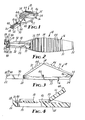
- FIG. 1 through 8 a first embodiment of.a stapler according to the present invention generally designated by the reference numeral 10.
- the stapler 10 is adapted for joining disunited skin by closing a staple 12 which, when open (see Figures 2 and 5), is generally W-shaped, has a planar side surface, and has points 14 on its opposite ends.
- the stapler 10 comprises an elongate polymeric molding 16 (see Figure 8) including a ram portion or ram 18 at one end having a distal end surface 19 adapted to engage the edge surface of the staple 12 opposite its points 14, and a body portion or body 20 at its end opposite the ram 18.
- the body 20 comprises a front end 22 at one end of the molding 16 and an opposite rear end 24, a staple guide surface 26 adjacent its front end 22, an anvil 28 transversely centered at its front end 22 projecting at a right angle to the staple guide surface 26, means adapted for mounting the staple 12 on the body 20 between its rear end 24 and the anvil 28 with one planar side surface of the staple 12 along the staple guide surface 26 and the points 14 of the staple 12 adjacent the front end 22 of the body 20, and means including opposed side walls 30 adapted for receiving the ram 18 on the body 20 for sliding movement from an open position with the end surface 19 of the ram 18 spaced from the anvil-28 to afford space for the open staple 12 therebetween ( Figures 1 through 5) to a closed position ( Figure 7) to cause the end surface 19 of the ram 18 to engage and bend the staple 12 closed around the anvil 28.
- the molding 16 also includes first and second drive portions or members 31 and 32 between the body 20 and the ram 18, a first thin transverse section 33 pivotably joining the ram 18 to the second drive member 32, a second thin transverse section 34 pivotably joining the drive members 31 and 32, and a third thin transverse section 35 joining the ends of the body 20 and the first drive member 31.
- the molding 16 can be bent at the thin sections 33, 34 and 35 to engage the ram 18 with the side walls 30 by inserting the distal end of the ram 18 between the ends of the side walls 30 opposite the anvil 28 and sliding the ram 18 between the side walls 30 until its end surface 19 contacts the open staple 12.
- the body 20 has optional transverse outwardly- projecting ridges 37 on its outer surface opposite the drive members 31 and 32 which restrict slippage of the user's fingers. Also the body 20 has a slightly arcuate cross section which both provides a slightly concave outer surface at the ridges 37 to receive a user's finger, and with the side walls 30 adjacent the anvil 28 restricts bending of the body 20 when force is applied to close the staple 12.
- the side walls 30 include lips projecting toward each other and spaced from the adjacent portion of the body 20, which spaces between the lips and adjacent portions of the body 20 receive and position edge portions of the ram 18 in a predetermined track extending longitudinally along the body 20. The lips project over elongate openings 39 in the adjacent portion of the body 20, which openings 39 facilitate molding of the lips.
- the means adapted for mounting the staple 12 on the body 20 include undercut projections 40 at the ends of the side walls 30 adjacent the anvil 28 and an undercut portion of the anvil 28 adjacent the side walls 30 which receive opposite sides of the staple 12 at spaced locations to position its planar side surface against the staple guide surface 26, its central portion against the anvil 28, and its points 14 about flush with the front end 22 of the body flanking and equally spaced from the anvil 28.
- the staple 12 can be releasably engaged with the projections 40 and anvil 28 to hold it in position prior to closing, and after a first staple 12 is closed, a second staple may be manually loaded into and closed by the stapler 10 if desired.
- the ram 18 has longitudinally-extending reinforcing ribs 42 which project upwardly from the ram 18 and center it between the lips on the side walls 30.
- a notch is centrally located across the end surface 19 of the ram 18 to receive the anvil 28 when the ram 18 is in its closed position, and the portions of the end surface 19 flanking the notch are centrally grooved in a direction parallel to the guide surface 26 to receive the edge surface of the staple 12 and help keep it in alignment with the guide surface 26 as it is closed.
- the drive members 31 and 32 have optional transverse ridges 44 on their surfaces that are opposite the body 20 when the ram 18 is in its open position to facilitate the grip of a user.
- the stapler 10 also includes means for biasing the ram 18 toward its open position after it is moved toward its closed position so that the ram 18 will separate from the closed staple 12 and facilitate removal of the anvil 28 from within the closed staple 12 with a moderate release of manual pressure on the drive members 31 and 32.
- the molding 16 includes an abutment 46 provided by a pair of spaced triangular parts formed on the body 20 and located between parts of the body 20 and of the first drive member 31 when the molding 16 is bent at the thin transverse sections 33, 34 and 35 and the ram 18 is engaged between the side walls 30 and positioned in its open position.
- the third thin transverse section 35 and the abutment 46 then cantilever mount the first drive member 31 so that it must be bent to move the ram 18 to its closed position during manual application of force to the drive members 31 and 32.
- the first drive member 31 is sufficiently resilient so that it will recover to return the ram 18 to adjacent its open position after pressure is released therefrom.
- a post 48 projects from the body 20 toward the juncture between the dr4-ve.members 31 and 32 to preclude movement of the drive members into an over center locking position as they are pressed toward the body 20 to close the staple 12.
- a preferred polymeric material for the molding 16 is the polycarbonate sold under the trade designation "Lexan” by General Electric Co., Schenectady, N.Y. which provides an acceptable combination of rigidity to afford forming of the staple by pressure from its surfaces, and flexibility for the thin transverse sections 33, 34 and 35 that allow them to be flexed without breaking for the small number of times required to close a small number of the staples 12.
- Other polymeric materials such as nylon, polypropylene, or high density polyethylene may also be suitable, however.
- the staple 12 is preferably of implant grade stainless steel, but could be made of other biologically acceptable metals such as some cobalt/chrome alloys. As shown in Figures 5, 6 and 7 the W-shaped open staple 12 is closed to a generally D-shaped closed staple 12 as is described in U.S. Patent No. 4,185,762 (incorporated herein by reference). In addition to the advantages with respect to the patient in which it is inserted described in U.S. Patent No.
- the generally W-shaped staple 12 provides the advantage of being closeable with a short movement of the ram between its open and closed position which allows a relatively small toggle joint linkage and facilitates a compact design for the stapler 10; while being closeable by a simple planar end surface normal to the length of the ram 18 rather than requiring the spaced staple-forming projections used in the stapler of U.S. Patent No. 4,202,480 which might have strength problems when made of polymeric materials.
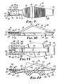
- Figures 9 and 10 illustrate a second embodiment of a stapler according to the present invention generally designated by the reference numeral 50.
- the stapler 50 is adapted for joining living tissue and comprises an elongate body 52 having front and rear ends 53 and 54, a guide surface 55 adjacent its front end 53, and an anvil 56 transversely centered at its front end 53 projecting at a right angle to the guide surface 55.
- Means are provided for mounting an open, generally W-shaped staple 58 having a generally planar side surface and pointed ends 60 on the body 52 adjacent the anvil 56 with the side surface of the staple 58 along the guide surface 55 and the points 60 of the staple 58 adjacent its front end 53.
- a ram 62 having an end surface 64 adapted to engage the edge surface of the staple 58 opposite its points 60 is mounted by means on the body 52 for movement from an open position with the end surface 64 of the ram 62 spaced from the anvil 56 to afford space for the open staple 58 therebetween to a closed position to cause the end surface of the ram 62 to engage and bend the staple closed around the anvil 56.
- a single toggle joint linkage 66 is attached between the rear end 54 of the body and the ram 62, which toggle joint linkage 66 has axes of pivotal movement that are parallel to the guide surface 55 so that the toggle joint assembly 66 projects from the body 52 in the open position of the ram 62 and is manually movable toward the body 52 to move the ram 62 to its closed position.
- the stapler 50 - comprises a polymeric molding 68 including first and second drive portions or members 69 and 70 that provide the toggle joint linkage 66 between the body 52 and ram 62, a first thin transverse section 71 pivotably joining the ram 62 to the second drive member 70, a second thin transverse section 72 pivotably joining the drive members 69 and 70, and a third thin transverse section 73 joining the rear end 54 of the body 52 and the first drive member 69.
- Parts of the body 52 and the first drive member 69 are spaced apart by an abutment 75 formed on the body 52 that provides means for biasing the first drive member to its open position by requiring it to resiliently bend so that it can move the ram 62 to its closed position.
- the body 52 of the stapler 50 is formed both by a part of the molding 68 and by a metal cover 76 fixed to the molding 68 by pins 78 and spaced from a portion of the molding 68 to provide a guide channel for the ram 62 therebetween.
- the guide surface 55 for the staple 58 and the anvil 56 are formed on the cover.
- the stapler 50 includes means for storing a reserve staple 77 within an opening in the body 52, which reserve staple 77 is pressed against the ram 62 by the distal end portion of a cantilevered spring-like portion 79 of the body 52.
- the reserve staple 77 can be moved onto the guide surface 55 by manually pulling the ram 62 to a third load position on the side of its open position opposite its closed position by lifting the drive members 69 and 70 away from the body 52, whereupon the spring-like portion 79 of the body 52 will move the reserve staple 77 so that it engages the guide surface 55 on the inner side of the cover 76, and subsequent movement of the ram 62 back to its open position will cause the ram 62 to move the reserve staple 77 to a position in engagement with the anvil 56, so that it can be closed by subsequent movement of the ram 62 to its closed position.
- the ram 62 of the stapler 50 is formed both by a part of the molding 68 and by a metal end plate on which the end surface 64 is formed.
- the molding and end plate parts of the ram 62 are locked together by a T-shaped tab 74 on the molding 68 that engages a mating slot through the end plate.
- FIGS 11 and 12 illustrate yet a third embodiment.of a stapler according to the present invention generally designated by the reference numeral 80.
- the stapler 80 is adapted for joining living tissue and comprises an elongate body 82 having front and rear ends 83 and 84, a guide surface 85 adjacent its front end 83, and an anvil 86 transversely centered at its front end 83 projecting at a right angle to the guide surface 85.
- Means are provided 1 for mounting an open, generally W-shaped staple 88 having a generally planar side surface and pointed ends 90 on the body 82 between its rear end 84 and the anvil 86 with the side surface of the staple 88 along the guide surface 85 and the points 90 of the staple 88 adjacent the front end 83 of the body 82.
- a ram 92 having an end surface 94 adapted to engage the edge surface of the staple 88 opposite its points 90 is mounted by means on the body 82 for movement from an open position with the end surface 94 of the ram 92 spaced from the anvil 86 to afford space for the open staple 88 therebetween to a closed position to cause the end surface 94 of the ram 92 to engage and bend the staple 88 closed around the anvil 86.
- a toggle joint linkage 96 is attached between the rear end 84 of the body 82 and the ram 92, which toggle joint linkage 96 has axes of pivotal movement that are parallel to the guide surface 85 so that the toggle joint linkage 96 projects from the body 82 in the open position of the ram 92 and is manually movable toward the body 82 to move the ram 92 to its closed position.
- the stapler 80 comprises a polymeric molding 98 including first and second drive portions or members 99 and 100 that provide the toggle joint linkage 96 between the body 82 and ram 92, a first thin transverse section 101 pivotably joining the ram 92 to the second drive member 100, a second thin transverse section 102 pivotably joining the drive members 99 and 100, and a third thin transverse section 103 pivotably joining the rear end 84 of the body 82 and the first drive member 99.
- a U-shaped end portion 104 of a spring 105 fixed to the body 82 by a rivet 110 provides means for biasing the first drive member 99 to its open position rather than by requiring the first drive member 99 to be resiliently bent upon movement of the ram 92 to its closed position.
- the body 82 and drive portions 99 and 100 have much larger transverse ridges 111 that locate the fingers during use of the stapler 80.
- the body 82 of the stapler 80 also is formed both by a part of the molding 98 and by a metal cover 106 fixed to the molding by pins 108 and spaced from the part of the molding 98 to provide a guide channel for the ram 92 therebetween.
- the guide surface 85 for the staple 88 and the anvil 86 are formed on the cover 106.
- the stapler 80 includes means for storing a small number of reserve staples 107 (e.g., at least 4 or 5 and conceivably up to 15) within an opening in the body 82, which reserve staples 107 are pressed against the ram 92 by an L-shaped distal end portion 109 of the spring 105 opposite the portion 104.
- the reserve staples 107 can be moved singly onto the guide surface 85 by manually pulling the ram 92 to a third load position on the side of its open position opposite its closed position by lifting the drive members 99 and 100 away from the body 82 (which lifting is facilitated by the U-shaped portion 104 of the spring 105), whereupon the L-shaped end portion 109 of the spring 105 will move the reserve staples 107 so that the reserve staple 107 adjacent the cover 106 engages the guide surface 85, and subsequent movement of the ram 92 back to its open position will cause the ram 92 to move the reserve staple 107 engaging the guide surface 85 to a position in engagement with the anvil 86, so that it can be closed by subsequently moving the ram 92 to its closed position.
- the ram 92 of the stapler 80 is formed both by a part of the molding 98 and by a metal end plate on which the end surface 94 is formed.
- the molding 98 and the end plate of the ram 92 are locked together by a T-shaped tab 112 on the molding 98 that engages a mating slot through the end plate.
- the stapler embodiments 10, 50, and 80 disclosed herein ray be subject to many modifications and alterations without departing from the scope of the invention.
- the metal end plates on the rams of the staplers 50 and 80 could be shaped like that of the ram in U.S. Patent No. 4,202,480 and one or more generally U-shaped staples could be applied via the stapler; or the body, ram, and the members forming the toggle joint linkage could be formed of metal, and the hinge points of the toggle joint linkage could be joined by conventional hinge pin structures or by flexible connecting material such as tape.
- the scope of the present invention should not be limited by the structures of the embodiments disclosed, but only by the structure described by language of the claims and its equivalents.
Abstract
Description
- This invention relates to staplers of the type adapted to join living tissue.
- Staplers adapted to join living tissue are well known. The earliest known type of staplers for such use were designed to be reusable and included high quality castings and machined parts of easily cleanable and sterilizable materials such as stainless steel (see, for example, the staplers described in U.S. Patents Nos. 3,643,851, 3,819,100 and 3,873,016). Such staplers typically are sterilized before each use in sterilizing equipment located at the facility (e.g., a hospital) in which they are used. The high cost of disassembling, cleaning and sterilizing such staplers before each use makes their use uneconomical where only a few staples are to be applied to a patient. Also the time needed for the sterilization procedure between successive uses of such staplers further restricts their use where a series of patients may each need the application of only a few staples, such as may occur in a hospital emergency room.
- More recently introduced types of staplers for joining living tissue are designed to be disposable (see for example the staplers described in U.S. Patents Nos. 4,109,844, 4,202,480 and 4,256,251). Such disposable staplers are made of relatively inexpensive parts such as plastic moldings and metal stampings that are sterilized during manufacturing and are packaged so that they remain sterilized until they are used. Such staplers are intended for use on only one patient, however. Thus, while due to the savings in cleaning and sterilization costs their use may be less expensive than that of reusable staplers where approximately the quantity of staples packaged in the stapler is to be used (e.g., 15 to 30 staples), and the use z of different sterilized staplers precludes problems of waiting for a single stapler to be resterilized between usages; the use of such disposable staplers is still uneconomical where only a few staples (e.g., less than 10) are to be used in a patient.
- Of the known prior art staplers of the above types, the one having a structure closest to the present invention appears to be the disposable type stapler described in U.S. Patent No. 4,202,480. That stapler comprises an elongate body having a guide surface adjacent a front end of the body, and an anvil transversely centered at the front end projecting at a right angle to the guide surface. Means are provided for feeding staples onto the guide surface with points of the staples adjacent the front end of the body, and a ram is mounted on the body for movement from an open position to a closed position to cause the ram to bend a staple on the guide surface closed around the anvil. The ram can be manually moved by a pair of toggle joint linkages attached between a rear end of the body and the ram. The toggle joint linkages are opposed and project away from opposite sides of the body when the ram is in its retracted position so that pressing the toggle joint linkages toward each other in a direction transverse to the guideway will move the ram from its open to its closed position. An improved version of that stapler has been sold for over 12 months under the trademark "Precise" by Minnesota Mining and Manufacturing Company of St. Paul, Minnesota, and has been found to be an effective mechanism for applying staples. Like the other disposable staplers on the market, however, its mechanism is too complex to make the stapler economical to apply only a few staples.
- The present invention provides an effective, inexpensive, disposable-type stapler that is economical to use when only a small number of staples (e.g., 1 to 10) are to be applied to a patient.
- According to the present invention there is provided a stapler which, like the stapler described in U.S. Patent No. 4,202,480, comprises an elongate body, a guide surface adjacent a front end of the stapler, and an anvil transversely centered at its front end projecting at a right angle to the guide surface. Means are provided for positioning a staple on the body adjacent the anvil with a side surface of the staple along the guide surface and the points of the staple adjacent the front end of the body. A ram having an end surface adapted to engage the edge surface of the staple opposite its points is mounted on the body for movement from an open position with the end surface of the ram spaced from the anvil to afford space for the open staple therebetween, to a closed position to cause the end surface of the ram to engage and bend the staple closed around the anvil. Also a toggle joint linkage is attached between the rear end of the body and the ram so that the toggle joint linkage projects from the body in the open position of the ram and is manually movable toward the body to move the ram to its closed position.
- Unlike the stapler described in U.S. Patent No. 4,202,480, however, the stapler according to the present invention has a novel greatly simplified design that includes only a single toggle joint linkage in which pivotal movement of the toggle joint linkage occurs around axes parallel to the guide surface; which toggle joint linkage is activated to form the staple by pressing it toward the body of the stapler.
- Preferably the stapler according to the present invention is adapted to use with a generally W-shaped staple of the type described in U.S. Patent No. 4,185,762 which requires a less complex and rugged ram to form the staple than does the generally U-shaped staple described in U.S.
- Patent No. 4,185,762.
- In a preferred, very inexpensive embodiment, the body, the ram, and first and second drive members which provide the toggle joint linkage of the stapler are formed in their entirety as a unitary polymeric molding and are joined by thin, flexible, transverse sections of the molding. The molding is elongate with the body at one end and the ram at the other. A single staple can be releasably loaded on the means for positioning a staple (which is provided by grooves that receive the staple with its center portion against the anvil), and the stapler can be packaged and sterilized. Before use, the thin transverse sections of the molding are bent and the ram is engaged with means mounting the ram on the body for movement between its open and closed position (which can be done by the manufacturer prior to packaging or by the user subsequent to opening the packaging), whereupon the toggle joint linkage projects from one side of the body and can be squeezed toward the body to close the staple and engage it to close the disunited tissue or skin of a patient. The ram may then be retracted, a second sterilized staple loaded into the means for positioning a staple, and the second staple applied to a patient; or more conveniently, the used stapler may be discarded and a second stapler used to apply a second staple. In either event the stapler provides a quick, convenient, inexpensive device for applying a few staples that is wholly suitable for use where a series of applications of a few staples each are desired such as in an emergency room of a hospital.
- Also preferably, the stapler includes means for biasing the ram to its open position that facilitates withdrawing the anvil from within the closed staple, and that can also facilitate reloading the stapler described should that be desired. Preferably the means for biasing comprises means for mounting the body to the first drive portion so that the first drive portion must be resiliently bent to move the ram to its closed position and will recover to return the ram to adjacent its open position upon the release of force applied.to the toggle joint linkage; however more conventional springs can also be used.
- The present invention will be more thoroughly described with reference to the accompanying drawing wherein like numbers refer to like parts in the several views, and wherein:
- Figure 1 is a perspective view of a first embodiment of a stapler according to the present invention;
- Figure 2 is a top view of the stapler shown in Figure 1;
- Figure 3 is a side view of the stapler shown in Figure 1;
- Figure 4 is an enlarged fragmentary sectional view taken approximately along line 4-4 of Figure 2;
- Figures 5, 6 and 7 are enlarged fragmentary top views of the stapler shown in Figure 1 which sequentially illustrate the forming of a staple by the stapler;
- Figure 8 is a top view of a molding comprising the stapler shown in Figure 1;
- Figure 9 is a top view of a second embodiment of a stapler according to the present invention having parts broken away to show detail;
- Figure 10 is a side view of the stapler of Figure 9;
- Figure 11 is a top view of a third embodiment of a stapler according to the present invention having parts broken away to show detail; and
- Figure 12 is a side view of the stapler shown in Figure 11 having parts broken away to show detail.
- Referring now to the drawing there is shown in Figures 1 through 8 a first embodiment of.a stapler according to the present invention generally designated by the
reference numeral 10. - The
stapler 10 is adapted for joining disunited skin by closing astaple 12 which, when open (see Figures 2 and 5), is generally W-shaped, has a planar side surface, and haspoints 14 on its opposite ends. Thestapler 10 comprises an elongate polymeric molding 16 (see Figure 8) including a ram portion orram 18 at one end having adistal end surface 19 adapted to engage the edge surface of thestaple 12 opposite itspoints 14, and a body portion orbody 20 at its end opposite theram 18. Thebody 20 comprises afront end 22 at one end of themolding 16 and an oppositerear end 24, astaple guide surface 26 adjacent itsfront end 22, ananvil 28 transversely centered at itsfront end 22 projecting at a right angle to thestaple guide surface 26, means adapted for mounting thestaple 12 on thebody 20 between itsrear end 24 and theanvil 28 with one planar side surface of thestaple 12 along thestaple guide surface 26 and thepoints 14 of thestaple 12 adjacent thefront end 22 of thebody 20, and means including opposedside walls 30 adapted for receiving theram 18 on thebody 20 for sliding movement from an open position with theend surface 19 of theram 18 spaced from the anvil-28 to afford space for theopen staple 12 therebetween (Figures 1 through 5) to a closed position (Figure 7) to cause theend surface 19 of theram 18 to engage and bend thestaple 12 closed around theanvil 28. Themolding 16 also includes first and second drive portions ormembers body 20 and theram 18, a first thintransverse section 33 pivotably joining theram 18 to thesecond drive member 32, a second thintransverse section 34 pivotably joining thedrive members transverse section 35 joining the ends of thebody 20 and thefirst drive member 31. Themolding 16 can be bent at thethin sections ram 18 with theside walls 30 by inserting the distal end of theram 18 between the ends of theside walls 30 opposite theanvil 28 and sliding theram 18 between theside walls 30 until itsend surface 19 contacts theopen staple 12. In the open position of the ram 18 (see Figures 1 through 5) thedrive members body 20 to provide a single toggle joint linkage adapted to be manually pressed toward thebody 20 to move theram 18 to its closed position to close thestaple 12 around theanvil 28. - The
body 20 has optional transverse outwardly- projectingridges 37 on its outer surface opposite thedrive members body 20 has a slightly arcuate cross section which both provides a slightly concave outer surface at theridges 37 to receive a user's finger, and with theside walls 30 adjacent theanvil 28 restricts bending of thebody 20 when force is applied to close thestaple 12. Theside walls 30 include lips projecting toward each other and spaced from the adjacent portion of thebody 20, which spaces between the lips and adjacent portions of thebody 20 receive and position edge portions of theram 18 in a predetermined track extending longitudinally along thebody 20. The lips project overelongate openings 39 in the adjacent portion of thebody 20, whichopenings 39 facilitate molding of the lips. - The means adapted for mounting the
staple 12 on thebody 20 includeundercut projections 40 at the ends of theside walls 30 adjacent theanvil 28 and an undercut portion of theanvil 28 adjacent theside walls 30 which receive opposite sides of thestaple 12 at spaced locations to position its planar side surface against thestaple guide surface 26, its central portion against theanvil 28, and itspoints 14 about flush with thefront end 22 of the body flanking and equally spaced from theanvil 28. Thestaple 12 can be releasably engaged with theprojections 40 and anvil 28 to hold it in position prior to closing, and after afirst staple 12 is closed, a second staple may be manually loaded into and closed by thestapler 10 if desired. - The
ram 18 has longitudinally-extendingreinforcing ribs 42 which project upwardly from theram 18 and center it between the lips on theside walls 30. A notch is centrally located across theend surface 19 of theram 18 to receive theanvil 28 when theram 18 is in its closed position, and the portions of theend surface 19 flanking the notch are centrally grooved in a direction parallel to theguide surface 26 to receive the edge surface of the staple 12 and help keep it in alignment with theguide surface 26 as it is closed. - The
drive members transverse ridges 44 on their surfaces that are opposite thebody 20 when theram 18 is in its open position to facilitate the grip of a user. - The
stapler 10 also includes means for biasing theram 18 toward its open position after it is moved toward its closed position so that theram 18 will separate from theclosed staple 12 and facilitate removal of theanvil 28 from within theclosed staple 12 with a moderate release of manual pressure on thedrive members molding 16 includes anabutment 46 provided by a pair of spaced triangular parts formed on thebody 20 and located between parts of thebody 20 and of thefirst drive member 31 when themolding 16 is bent at the thintransverse sections ram 18 is engaged between theside walls 30 and positioned in its open position. The third thintransverse section 35 and theabutment 46 then cantilever mount thefirst drive member 31 so that it must be bent to move theram 18 to its closed position during manual application of force to thedrive members first drive member 31 is sufficiently resilient so that it will recover to return theram 18 to adjacent its open position after pressure is released therefrom. Also, apost 48 projects from thebody 20 toward the juncture between the dr4-ve.members body 20 to close thestaple 12. - A preferred polymeric material for the
molding 16 is the polycarbonate sold under the trade designation "Lexan" by General Electric Co., Schenectady, N.Y. which provides an acceptable combination of rigidity to afford forming of the staple by pressure from its surfaces, and flexibility for the thintransverse sections staples 12. Other polymeric materials such as nylon, polypropylene, or high density polyethylene may also be suitable, however. - The staple 12 is preferably of implant grade stainless steel, but could be made of other biologically acceptable metals such as some cobalt/chrome alloys. As shown in Figures 5, 6 and 7 the W-shaped
open staple 12 is closed to a generally D-shapedclosed staple 12 as is described in U.S. Patent No. 4,185,762 (incorporated herein by reference). In addition to the advantages with respect to the patient in which it is inserted described in U.S. Patent No. 4,185,762, the generally W-shapedstaple 12 provides the advantage of being closeable with a short movement of the ram between its open and closed position which allows a relatively small toggle joint linkage and facilitates a compact design for thestapler 10; while being closeable by a simple planar end surface normal to the length of theram 18 rather than requiring the spaced staple-forming projections used in the stapler of U.S. Patent No. 4,202,480 which might have strength problems when made of polymeric materials. - Figures 9 and 10 illustrate a second embodiment of a stapler according to the present invention generally designated by the
reference numeral 50. - Like the
stapler 10, thestapler 50 is adapted for joining living tissue and comprises anelongate body 52 having front andrear ends guide surface 55 adjacent itsfront end 53, and ananvil 56 transversely centered at itsfront end 53 projecting at a right angle to theguide surface 55. Means are provided for mounting an open, generally W-shapedstaple 58 having a generally planar side surface and pointed ends 60 on thebody 52 adjacent theanvil 56 with the side surface of the staple 58 along theguide surface 55 and the points 60 of the staple 58 adjacent itsfront end 53. Aram 62 having anend surface 64 adapted to engage the edge surface of the staple 58 opposite its points 60 is mounted by means on thebody 52 for movement from an open position with theend surface 64 of theram 62 spaced from theanvil 56 to afford space for theopen staple 58 therebetween to a closed position to cause the end surface of theram 62 to engage and bend the staple closed around theanvil 56. A single togglejoint linkage 66 is attached between therear end 54 of the body and theram 62, which togglejoint linkage 66 has axes of pivotal movement that are parallel to theguide surface 55 so that the togglejoint assembly 66 projects from thebody 52 in the open position of theram 62 and is manually movable toward thebody 52 to move theram 62 to its closed position. - Also like the
stapler 10, the stapler 50 - comprises apolymeric molding 68 including first and second drive portions ormembers joint linkage 66 between thebody 52 andram 62, a first thintransverse section 71 pivotably joining theram 62 to thesecond drive member 70, a second thintransverse section 72 pivotably joining thedrive members transverse section 73 joining therear end 54 of thebody 52 and thefirst drive member 69. Parts of thebody 52 and thefirst drive member 69 are spaced apart by anabutment 75 formed on thebody 52 that provides means for biasing the first drive member to its open position by requiring it to resiliently bend so that it can move theram 62 to its closed position. - Unlike the
stapler 10, however, thebody 52 of thestapler 50 is formed both by a part of themolding 68 and by ametal cover 76 fixed to themolding 68 bypins 78 and spaced from a portion of themolding 68 to provide a guide channel for theram 62 therebetween. Theguide surface 55 for the staple 58 and theanvil 56 are formed on the cover. Also, thestapler 50 includes means for storing a reserve staple 77 within an opening in thebody 52, which reserve staple 77 is pressed against theram 62 by the distal end portion of a cantilevered spring-like portion 79 of thebody 52. The reserve staple 77 can be moved onto theguide surface 55 by manually pulling theram 62 to a third load position on the side of its open position opposite its closed position by lifting thedrive members body 52, whereupon the spring-like portion 79 of thebody 52 will move the reserve staple 77 so that it engages theguide surface 55 on the inner side of thecover 76, and subsequent movement of theram 62 back to its open position will cause theram 62 to move the reserve staple 77 to a position in engagement with theanvil 56, so that it can be closed by subsequent movement of theram 62 to its closed position. - Also, the
ram 62 of thestapler 50 is formed both by a part of themolding 68 and by a metal end plate on which theend surface 64 is formed. The molding and end plate parts of theram 62 are locked together by a T-shapedtab 74 on themolding 68 that engages a mating slot through the end plate. - Figures 11 and 12 illustrate yet a third embodiment.of a stapler according to the present invention generally designated by the
reference numeral 80. - Like the
staplers stapler 80 is adapted for joining living tissue and comprises anelongate body 82 having front andrear ends guide surface 85 adjacent itsfront end 83, and ananvil 86 transversely centered at itsfront end 83 projecting at a right angle to theguide surface 85. Means are provided 1 for mounting an open, generally W-shapedstaple 88 having a generally planar side surface and pointed ends 90 on thebody 82 between itsrear end 84 and theanvil 86 with the side surface of the staple 88 along theguide surface 85 and thepoints 90 of the staple 88 adjacent thefront end 83 of thebody 82. A ram 92 having an end surface 94 adapted to engage the edge surface of the staple 88 opposite itspoints 90 is mounted by means on thebody 82 for movement from an open position with the end surface 94 of the ram 92 spaced from theanvil 86 to afford space for theopen staple 88 therebetween to a closed position to cause the end surface 94 of the ram 92 to engage and bend the staple 88 closed around theanvil 86. A togglejoint linkage 96 is attached between therear end 84 of thebody 82 and the ram 92, which togglejoint linkage 96 has axes of pivotal movement that are parallel to theguide surface 85 so that the togglejoint linkage 96 projects from thebody 82 in the open position of the ram 92 and is manually movable toward thebody 82 to move the ram 92 to its closed position. - Also like the
staplers stapler 80 comprises apolymeric molding 98 including first and second drive portions ormembers joint linkage 96 between thebody 82 and ram 92, a first thintransverse section 101 pivotably joining the ram 92 to thesecond drive member 100, a second thintransverse section 102 pivotably joining thedrive members transverse section 103 pivotably joining therear end 84 of thebody 82 and thefirst drive member 99. Unlike the other embodiments, however, aU-shaped end portion 104 of aspring 105 fixed to thebody 82 by arivet 110 provides means for biasing thefirst drive member 99 to its open position rather than by requiring thefirst drive member 99 to be resiliently bent upon movement of the ram 92 to its closed position. Also, thebody 82 and driveportions stapler 80. - Like the
body 52 of thestapler 50, thebody 82 of thestapler 80 also is formed both by a part of themolding 98 and by ametal cover 106 fixed to the molding bypins 108 and spaced from the part of themolding 98 to provide a guide channel for the ram 92 therebetween. Theguide surface 85 for the staple 88 and theanvil 86 are formed on thecover 106. Also, thestapler 80 includes means for storing a small number of reserve staples 107 (e.g., at least 4 or 5 and conceivably up to 15) within an opening in thebody 82, which reservestaples 107 are pressed against the ram 92 by an L-shapeddistal end portion 109 of thespring 105 opposite theportion 104. - The
reserve staples 107 can be moved singly onto theguide surface 85 by manually pulling the ram 92 to a third load position on the side of its open position opposite its closed position by lifting thedrive members U-shaped portion 104 of the spring 105), whereupon the L-shapedend portion 109 of thespring 105 will move thereserve staples 107 so that thereserve staple 107 adjacent thecover 106 engages theguide surface 85, and subsequent movement of the ram 92 back to its open position will cause the ram 92 to move thereserve staple 107 engaging theguide surface 85 to a position in engagement with theanvil 86, so that it can be closed by subsequently moving the ram 92 to its closed position. - Also, like the
ram 62 of thestapler 50, the ram 92 of thestapler 80 is formed both by a part of themolding 98 and by a metal end plate on which the end surface 94 is formed. Themolding 98 and the end plate of the ram 92 are locked together by a T-shapedtab 112 on themolding 98 that engages a mating slot through the end plate. - It will be understood that the
stapler embodiments staplers
Claims (7)
Applications Claiming Priority (2)
| Application Number | Priority Date | Filing Date | Title |
|---|---|---|---|
| US29906881A | 1981-09-03 | 1981-09-03 | |
| US299068 | 1981-09-03 |
Publications (3)
| Publication Number | Publication Date |
|---|---|
| EP0074744A2 true EP0074744A2 (en) | 1983-03-23 |
| EP0074744A3 EP0074744A3 (en) | 1983-12-21 |
| EP0074744B1 EP0074744B1 (en) | 1986-03-26 |
Family
ID=23153188
Family Applications (1)
| Application Number | Title | Priority Date | Filing Date |
|---|---|---|---|
| EP82304545A Expired EP0074744B1 (en) | 1981-09-03 | 1982-08-27 | Stapler |
Country Status (11)
| Country | Link |
|---|---|
| EP (1) | EP0074744B1 (en) |
| JP (1) | JPS5850947A (en) |
| AU (1) | AU546233B2 (en) |
| BR (1) | BR8205148A (en) |
| CA (1) | CA1182709A (en) |
| DE (1) | DE3270123D1 (en) |
| HK (1) | HK99987A (en) |
| MX (1) | MX154382A (en) |
| SG (1) | SG73287G (en) |
| SU (1) | SU1429926A3 (en) |
| ZA (1) | ZA826439B (en) |
Cited By (1)
| Publication number | Priority date | Publication date | Assignee | Title |
|---|---|---|---|---|
| EP0229453A2 (en) * | 1985-11-01 | 1987-07-22 | Senmed, Inc. | Disposable stapler |
Families Citing this family (4)
| Publication number | Priority date | Publication date | Assignee | Title |
|---|---|---|---|---|
| US8267945B2 (en) * | 2009-10-09 | 2012-09-18 | Ethicon Endo-Surgery, Inc. | Clip advancer with lockout mechanism |
| US8262679B2 (en) * | 2009-10-09 | 2012-09-11 | Ethicon Endo-Surgery, Inc. | Clip advancer |
| JP6091798B2 (en) * | 2012-08-08 | 2017-03-08 | マニー株式会社 | Medical stapler anvil |
| US10918393B2 (en) * | 2017-11-05 | 2021-02-16 | Grena Usa Llc | Surgical appliance |
Citations (5)
| Publication number | Priority date | Publication date | Assignee | Title |
|---|---|---|---|---|
| DE2037710A1 (en) * | 1969-07-29 | 1971-02-18 | Imperial Chemical Industries Ltd. London | Surgical staple handling device |
| US3613683A (en) * | 1969-06-04 | 1971-10-19 | George Kees Jr | Clip-applying surgical instrument |
| FR2154047A5 (en) * | 1971-09-17 | 1973-05-04 | Ici Ltd | |
| US4185762A (en) * | 1978-03-27 | 1980-01-29 | Minnesota Mining And Manufacturing Company | Medical stapling device |
| US4256251A (en) * | 1978-04-24 | 1981-03-17 | Lawrence M. Smith | Surgical staplers and staple |
Family Cites Families (3)
| Publication number | Priority date | Publication date | Assignee | Title |
|---|---|---|---|---|
| GB1587058A (en) * | 1976-06-15 | 1981-03-25 | Beecham Group Ltd | Oxiranylmethyltetrahydropyran derivatives |
| US4202480A (en) * | 1979-02-26 | 1980-05-13 | Minnesota Mining And Manufacturing Company | Stapler including means for preventing double feeding of staples |
| JPS5746854A (en) * | 1980-07-24 | 1982-03-17 | Aisan Seisakusho:Kk | Double cup producing machine |
-
1982
- 1982-08-12 CA CA000409265A patent/CA1182709A/en not_active Expired
- 1982-08-27 DE DE8282304545T patent/DE3270123D1/en not_active Expired
- 1982-08-27 EP EP82304545A patent/EP0074744B1/en not_active Expired
- 1982-09-02 SU SU823489005A patent/SU1429926A3/en active
- 1982-09-02 AU AU87942/82A patent/AU546233B2/en not_active Ceased
- 1982-09-02 ZA ZA826439A patent/ZA826439B/en unknown
- 1982-09-02 MX MX194255A patent/MX154382A/en unknown
- 1982-09-02 BR BR8205148A patent/BR8205148A/en not_active IP Right Cessation
- 1982-09-02 JP JP57153339A patent/JPS5850947A/en active Granted
-
1987
- 1987-09-03 SG SG732/87A patent/SG73287G/en unknown
- 1987-12-24 HK HK999/87A patent/HK99987A/en not_active IP Right Cessation
Patent Citations (5)
| Publication number | Priority date | Publication date | Assignee | Title |
|---|---|---|---|---|
| US3613683A (en) * | 1969-06-04 | 1971-10-19 | George Kees Jr | Clip-applying surgical instrument |
| DE2037710A1 (en) * | 1969-07-29 | 1971-02-18 | Imperial Chemical Industries Ltd. London | Surgical staple handling device |
| FR2154047A5 (en) * | 1971-09-17 | 1973-05-04 | Ici Ltd | |
| US4185762A (en) * | 1978-03-27 | 1980-01-29 | Minnesota Mining And Manufacturing Company | Medical stapling device |
| US4256251A (en) * | 1978-04-24 | 1981-03-17 | Lawrence M. Smith | Surgical staplers and staple |
Cited By (3)
| Publication number | Priority date | Publication date | Assignee | Title |
|---|---|---|---|---|
| EP0229453A2 (en) * | 1985-11-01 | 1987-07-22 | Senmed, Inc. | Disposable stapler |
| EP0229453A3 (en) * | 1985-11-01 | 1987-09-30 | Senmed, Inc. | Disposable stapler |
| AU581349B2 (en) * | 1985-11-01 | 1989-02-16 | Senmed Inc. | Disposable stapler |
Also Published As
| Publication number | Publication date |
|---|---|
| SU1429926A3 (en) | 1988-10-07 |
| EP0074744A3 (en) | 1983-12-21 |
| HK99987A (en) | 1987-12-31 |
| MX154382A (en) | 1987-08-04 |
| DE3270123D1 (en) | 1986-04-30 |
| JPH0313896B2 (en) | 1991-02-25 |
| AU8794282A (en) | 1983-03-10 |
| CA1182709A (en) | 1985-02-19 |
| BR8205148A (en) | 1983-08-09 |
| EP0074744B1 (en) | 1986-03-26 |
| JPS5850947A (en) | 1983-03-25 |
| ZA826439B (en) | 1983-07-27 |
| AU546233B2 (en) | 1985-08-22 |
| SG73287G (en) | 1989-04-21 |
Similar Documents
| Publication | Publication Date | Title |
|---|---|---|
| EP0087938B1 (en) | Surgical clip applier with in-line cartridge and interruptable biased feeder | |
| EP0118262B1 (en) | Stapler including ratchet means for preventing double feeding of staples | |
| CA1235623A (en) | Apparatus for applying two-part surgical fasteners | |
| US4470532A (en) | Medical stapling device | |
| EP0537572B1 (en) | A locking device for an apparatus for applying surgical fasteners | |
| CA2102346C (en) | Rotatable articulating endoscopic fastening instrument | |
| US5894979A (en) | Surgical stapler with anvil sensor and lockout | |
| JP2656826B2 (en) | Surgical stapler | |
| EP0569049B1 (en) | A one-piece surgical staple | |
| EP0087939B1 (en) | Surgical clip applier with serpentine spring clip feeder | |
| US5104397A (en) | Multi-position latching mechanism for forceps | |
| CA1261226A (en) | Surgical stapling instrument with jaw latching mechanism and disposable staple cartridge | |
| JPS6224097B2 (en) | ||
| EP2875786A2 (en) | Apparatus for applying surgical clips | |
| JPS6290146A (en) | Surgical stapler | |
| JPS632617B2 (en) | ||
| EP0124556B1 (en) | Stapler with retractable anvil | |
| US4477008A (en) | Stapler | |
| US4477007A (en) | Stapler with intermediate latching mechanism | |
| EP0074744B1 (en) | Stapler | |
| EP0509513B1 (en) | Fasciaclip and instrument | |
| EP0070276B1 (en) | Surgical device | |
| KR20050016474A (en) | Surgical stapling device |
Legal Events
| Date | Code | Title | Description |
|---|---|---|---|
| PUAI | Public reference made under article 153(3) epc to a published international application that has entered the european phase |
Free format text: ORIGINAL CODE: 0009012 |
|
| AK | Designated contracting states |
Designated state(s): DE FR GB IT SE |
|
| PUAL | Search report despatched |
Free format text: ORIGINAL CODE: 0009013 |
|
| AK | Designated contracting states |
Designated state(s): DE FR GB IT SE |
|
| 17P | Request for examination filed |
Effective date: 19840601 |
|
| GRAA | (expected) grant |
Free format text: ORIGINAL CODE: 0009210 |
|
| ITF | It: translation for a ep patent filed |
Owner name: BARZANO' E ZANARDO ROMA S.P.A. |
|
| AK | Designated contracting states |
Kind code of ref document: B1 Designated state(s): DE FR GB IT SE |
|
| REF | Corresponds to: |
Ref document number: 3270123 Country of ref document: DE Date of ref document: 19860430 |
|
| ET | Fr: translation filed | ||
| PLBE | No opposition filed within time limit |
Free format text: ORIGINAL CODE: 0009261 |
|
| STAA | Information on the status of an ep patent application or granted ep patent |
Free format text: STATUS: NO OPPOSITION FILED WITHIN TIME LIMIT |
|
| 26N | No opposition filed | ||
| REG | Reference to a national code |
Ref country code: GB Ref legal event code: 732 |
|
| ITTA | It: last paid annual fee | ||
| EAL | Se: european patent in force in sweden |
Ref document number: 82304545.5 |
|
| PGFP | Annual fee paid to national office [announced via postgrant information from national office to epo] |
Ref country code: SE Payment date: 19950713 Year of fee payment: 14 |
|
| PG25 | Lapsed in a contracting state [announced via postgrant information from national office to epo] |
Ref country code: SE Effective date: 19960828 |
|
| EUG | Se: european patent has lapsed |
Ref document number: 82304545.5 |
|
| PGFP | Annual fee paid to national office [announced via postgrant information from national office to epo] |
Ref country code: FR Payment date: 20010801 Year of fee payment: 20 |
|
| PGFP | Annual fee paid to national office [announced via postgrant information from national office to epo] |
Ref country code: DE Payment date: 20010802 Year of fee payment: 20 |
|
| PGFP | Annual fee paid to national office [announced via postgrant information from national office to epo] |
Ref country code: GB Payment date: 20010803 Year of fee payment: 20 |
|
| REG | Reference to a national code |
Ref country code: GB Ref legal event code: IF02 |
|
| PG25 | Lapsed in a contracting state [announced via postgrant information from national office to epo] |
Ref country code: GB Free format text: LAPSE BECAUSE OF EXPIRATION OF PROTECTION Effective date: 20020826 |
|
| REG | Reference to a national code |
Ref country code: GB Ref legal event code: PE20 Effective date: 20020826 |