EP0075224A2 - Dispenser with an air pump mechanism - Google Patents
Dispenser with an air pump mechanism Download PDFInfo
- Publication number
- EP0075224A2 EP0075224A2 EP82108383A EP82108383A EP0075224A2 EP 0075224 A2 EP0075224 A2 EP 0075224A2 EP 82108383 A EP82108383 A EP 82108383A EP 82108383 A EP82108383 A EP 82108383A EP 0075224 A2 EP0075224 A2 EP 0075224A2
- Authority
- EP
- European Patent Office
- Prior art keywords
- valve
- piston
- air suction
- suction valve
- air
- Prior art date
- Legal status (The legal status is an assumption and is not a legal conclusion. Google has not performed a legal analysis and makes no representation as to the accuracy of the status listed.)
- Granted
Links
Images

Classifications
-
- B—PERFORMING OPERATIONS; TRANSPORTING
- B65—CONVEYING; PACKING; STORING; HANDLING THIN OR FILAMENTARY MATERIAL
- B65D—CONTAINERS FOR STORAGE OR TRANSPORT OF ARTICLES OR MATERIALS, e.g. BAGS, BARRELS, BOTTLES, BOXES, CANS, CARTONS, CRATES, DRUMS, JARS, TANKS, HOPPERS, FORWARDING CONTAINERS; ACCESSORIES, CLOSURES, OR FITTINGS THEREFOR; PACKAGING ELEMENTS; PACKAGES
- B65D83/00—Containers or packages with special means for dispensing contents
- B65D83/14—Containers or packages with special means for dispensing contents for delivery of liquid or semi-liquid contents by internal gaseous pressure, i.e. aerosol containers comprising propellant for a product delivered by a propellant
- B65D83/44—Valves specially adapted therefor; Regulating devices
- B65D83/48—Lift valves, e.g. operated by push action
-
- B—PERFORMING OPERATIONS; TRANSPORTING
- B05—SPRAYING OR ATOMISING IN GENERAL; APPLYING FLUENT MATERIALS TO SURFACES, IN GENERAL
- B05B—SPRAYING APPARATUS; ATOMISING APPARATUS; NOZZLES
- B05B9/00—Spraying apparatus for discharge of liquids or other fluent material, without essentially mixing with gas or vapour
- B05B9/03—Spraying apparatus for discharge of liquids or other fluent material, without essentially mixing with gas or vapour characterised by means for supplying liquid or other fluent material
- B05B9/04—Spraying apparatus for discharge of liquids or other fluent material, without essentially mixing with gas or vapour characterised by means for supplying liquid or other fluent material with pressurised or compressible container; with pump
- B05B9/08—Apparatus to be carried on or by a person, e.g. of knapsack type
- B05B9/0805—Apparatus to be carried on or by a person, e.g. of knapsack type comprising a pressurised or compressible container for liquid or other fluent material
- B05B9/0811—Apparatus to be carried on or by a person, e.g. of knapsack type comprising a pressurised or compressible container for liquid or other fluent material comprising air supplying means actuated by the operator to pressurise or compress the container
- B05B9/0816—Apparatus to be carried on or by a person, e.g. of knapsack type comprising a pressurised or compressible container for liquid or other fluent material comprising air supplying means actuated by the operator to pressurise or compress the container the air supplying means being a manually actuated air pump
- B05B9/0822—Apparatus to be carried on or by a person, e.g. of knapsack type comprising a pressurised or compressible container for liquid or other fluent material comprising air supplying means actuated by the operator to pressurise or compress the container the air supplying means being a manually actuated air pump a discharge device being fixed to the container
Definitions
- This invention relates to a dispenser with an air pump mechanism which dispenses fluid using compressed air stored previously in a container.
- the dispenser with the air pump mechanism which stores compressed air in a container by sliding a piston in a cylinder is well-known.
- a nozzle is moved downwards, not for pump operation, but only for opening a valve.
- liquid in the container is pressurized by compressed air and is continuously dispensed through the valve.
- the piston must be locked to reduce the projection from the dispenser as much as possible at the position where it is fully pushed in.
- a large force is required for locking because it is necessary for the piston to be pushed in against compressed air remaining in the cylinder.
- an air hole is adopted in a conventional method.
- the dispenser has no air hole and it is not necessary to close an air hole, thus, pump operation is not complicated. Compressed air remaining in the pressure chamber can be easily released into the atmosphere. Furthermore, compressed air in the container can be released into the atmosphere by moving the stem inwards in the container independently of the piston, parting it from the sleeve, contacting it with the pressure accumulating valve of the couple of valves, and opening the pressure accumulating valve.
- the stem since watertightness of the pressure chamber is accomplished by contacting the stem movable independently of the piston with the tubular sleeve fixed to the piston, the stem must be formed and arranged in accurate dimensions against the sleeve. In other words, the stem needs high accuracy in manufacturing and assembly.
- the dispenser with the air pump mechanism comprises an air suction valve which includes an axially flexible valve body, is installed at the internal end of the piston for allowing air flow only to the pressure chamber formed between the cylinder and the piston.
- the dispenser further comprises a release means which includes an elastic piece having axially flexible elasticity and is installed to the bottom of the piston, and a stem member fixed at one end to the bottom of the elastic piece and extending at the other end into the piston.
- the stem member has a pushing part to release the air suction valve by contacting the valve body of the air suction valve when the elastic piece is moved to the air suction valve. After accumulating pressure, therefore, compressed air remaining in the pressure chamber can be released into the atmosphere by pushing the bottom of the elastic piece in the pushing direction of the piston. Consequently, the pushing operation of the piston to the locking position can be easily carried out without resisting forces. In such a construction, it is not necessary to perform the pumping operation by closing an air hole as in a conventional method, and not only is the pumping operation done smoothly, but also the locking of the piston can be easily carried out.
- the stem member as the release means is used only for releasing the air suction valve and does not contribute at all to maintaining the watertightness of the air suction valve. Namely, the stem member is sufficient to release watertightness by contacting the valve body of the air suction valve when the elastic piece is moved toward the air suction valve, it needs no manufacturing and assembling accuracy.
- a dispenser 10 with an air pump mechanism comprises a valve housing 14 attached to the top of a metallic container 12 and a cylinder 16 attached to the bottom of the container.
- the valve housing 14 contains internally a conventional spraying valve (not shown), and the valve will be released by pushing downwards a push button 18 which is attached at the top of the valve housing 14 and is also used for a nozzle.
- a cover housing 21 is detachably attached so as to cover the push button 18 at the top of the container 12.
- the cylinder 16 is fitted with a tightening ring 19 to the curl edge at the bottom of the container 12 and is extended into the container.
- the cylinder 16 includes a pressure accumulating valve 22 at the internal end.
- the pressure accumulating valve 22 is a one-way valve which allows air flow only into the internal part of the container 12, and as shown in Figs. 2 and 3, the valve has a axially flexible valve body 28 which is connected to a body 24 through four flexible pieces 26. Attachment of the cylinder 16 to the container 12 may be screwed instead of fitted. In this case, supply of the fluid into the container 12 may be easily carried out.
- the cylinder 16 contains a hollow piston 30 which can move freely along the internal surface of the cylinder.
- An air pump mechanism 31 is composed of the cylinder 16 and the piston 30.
- the piston 30 includes an air suction valve 34 which is a one-way valve allowing air flow into a pressure chamber 32 formed by the cylinder 16 and the piston.
- the air suction valve 34 as shown in Fig. 4, includes a valve body 40 which is axially flexible and is connected with three flexible pieces 38 to a body 36, and a skirt-like seal piece 42 formed on the periphery of the body 36. As shown in Fig.
- the valve body 40 is installed at the location a little apart from the upper end of the piston 30 serving as a valve seat and prevents chattering of the valve body during the drawing stroke of the piston. It is a matter of course that the valve 34 will be closed by the valve body 40 being pushed and contacting the upper end of the piston by compressed air generated in the pressure chamber 32 during the pushing stroke of the piston 30.
- the piston 30 has a stopper, the inclined surface 44 for example, in it's internal part, and the inclined surface 44 is, as described later, formed so as to be able to contact the shoulder 52 of the stem member 48.
- the stopper 44 may be axially moved and located at the center or outer end of the piston instead of at the internal end of the piston as shown in Fig. 1.
- the dispenser 10 further comprises a release means ⁇ 46.
- the releases means 46 includes an elastic piece 50 having axially flexible elasticity such as the cylindrical part with bottom and a stem member 48 which has a cross- shaped section and is attached to the bottom of the cylindrical part 50 at it's one end.
- the stem member 48 has an inclined shoulder 52 at the internal end in an adjacent position, and also has the pushing part, such as a cylindrical part 54, at the internal end, and the shoulder 52 is formed so as to be able to contact the inclined surface 44 of the piston 30, and the cylindrical part 54 is formed so as to be able to push the valve body 40 of the air suction valve 34.
- the cylindrical part 50 with bottom comprises a plurality of air-inlet holes 55 for instance, four, and is, as shown in Fig. 1, fitted with the bottom of the cylinder 30.
- the stem member 48 attached to the cylindrical part 50 extends into the piston 30, pushing the bottom of the cylindrical part 50, the stem member 48 is raised up to contact the cylindrical part 54 with the valve body 40, and the valve body is pushed upwards. Upward movement of the stem member 48 is limited by contacting the shoulder 52 with the inclined surface 44.
- the piston 30 will be joined as loading and unloading can be carried out freely by joining the annular joint 60 directly or indirectly to the curl edge of the container 12 with the tightening ring 19.
- the means to lock the piston 30 to the container 12 during spraying operation of the dispenser 10 are not limited to the above-mentioned construction using the curl edge, and other various constructions, for example a construction to use a joining groove and a joining projection etc, will be available.
- the dispenser 10 constructed as mentioned above is operated in the following manner.
- the piston 30 will be reciprocated in the cylinder 16.
- the release means 46 will move together with the piston 30, and the air suction valve 34 will not be released.
- the drawing stroke of the piston 30 will increase the inner volume of the pressure chamber 32 and pressure will become negative in the pressure chamber.
- the valve body 40 will be moved toward the pressure chamber 32, and the air suction valve 34 will be released and the skirt-like seal piece 42 will be deformed simultaneously. Air in the cylinder 16 and air flowed into the piston 30 through air-inlet holes 55 will flow into the pressure chamber 32 through the skirt-like seal piece 42 and the valve body 40.
- the pushing stroke of the piston 30 will compress air in the pressure chamber 32 and the air will flow into the container 12 through the pressure accumulating valve 22 to be stored at high pressure. Repetition of the above reciprocating operation of the piston 30 will increase pressure of accumulated air in the container 12. As accumulation of pressure proceeds, compressed air in the container 12 will act as a resisting force against the piston 30, and the reciprocating motion of the piston will become dull. After the compressed air is fully accumulated, in order for the piston 30 to be pushed into it's locked position, a large force is required because the pressure of compressed air remaining in the pressure chamber 32 acts as a resisting force against the piston. Then, in Fig. 1, the bottom of the cylindrical part 50 of the release means 46 is pushed upwards.
- the stem member 48 will go up, contacting the cylindrical part 54 with the valve body 40, pushing the valve body upwards to be apart from the valve seat 41, and the air suction valve 34 will be released. For this reason, compressed air remaining in the pressure chamber 32 will flow into the piston 30 and will then be released into the atmosphere through the air-inlet holes 55. The resisting force acting on the piston 30 is, therefore, removed, and the piston can be easily pushed into the locked position.
- the spraying valve (not shown) will be opened and fluid pushed by compressed air accumulated in the container 12 will go up through the suction tube 20 and will be continually sprayed outwards through the nozzle (not shown).
- the stem member 48 does not contribute at all to watertightness maintaining of the air suction valve 34.
- the stem member 48 only acts to release the watertightness by contacting the valve body 36 of the air suction valve 34 when the elastic piece 50 is moved toward the air suction valve 34. Since the travelling length of the elastic piece 50 can be set to sufficient length, the stem member 48 does not require accuracy in dimensions and assembly.
- the dispenser may be embodied as a foamer by setting a barrier in the fluid pass instead of the spraying valve used in the above example.
Abstract
Description
- This invention relates to a dispenser with an air pump mechanism which dispenses fluid using compressed air stored previously in a container.
- The dispenser with the air pump mechanism which stores compressed air in a container by sliding a piston in a cylinder is well-known. In this dispenser, a nozzle is moved downwards, not for pump operation, but only for opening a valve. When the nozzle comes down, liquid in the container is pressurized by compressed air and is continuously dispensed through the valve. During dispensing operation the piston must be locked to reduce the projection from the dispenser as much as possible at the position where it is fully pushed in. However, a large force is required for locking because it is necessary for the piston to be pushed in against compressed air remaining in the cylinder. To remove such a defect, an air hole is adopted in a conventional method. The air hole is closed during pump operation and opened after the pump stops in order to release compressed air remaining in the cylinder into the atmosphere, then the resisting force against the piston locking is removed. However, this construction having such an air hole has the disadvantage of complicated pump operation because not only must the air hole be closed during pump operation, but also closure of the air hole must be maintained by adding a large force against residual compressed air.
- The dispenser with the air pump mechanism with no air hole for residual compressed air has been published in U.S.P. No. 3,955,720 (issued on May 11, 1976 to D.C. Malone). According to the Malone patent, a movable stem is installed in the inside of the piston and the stem is moved with the piston during pump operation. The tip of the stem keeps watertight the pressure chamber formed between a couple of valves by being contact with the tubular sleeve installed in the inside of the piston. Compressed air remaining in the pressure chamber is released into the atmosphere through a clearance between the stem and sleeve, releasing the seal between them by moving the stem outwards independently of the piston and parting it from the sleeve. As mentioned above, according to the Malone patent, the dispenser has no air hole and it is not necessary to close an air hole, thus, pump operation is not complicated. Compressed air remaining in the pressure chamber can be easily released into the atmosphere. Furthermore, compressed air in the container can be released into the atmosphere by moving the stem inwards in the container independently of the piston, parting it from the sleeve, contacting it with the pressure accumulating valve of the couple of valves, and opening the pressure accumulating valve. However, since watertightness of the pressure chamber is accomplished by contacting the stem movable independently of the piston with the tubular sleeve fixed to the piston, the stem must be formed and arranged in accurate dimensions against the sleeve. In other words, the stem needs high accuracy in manufacturing and assembly.
- It is therefore an object of this invention to provide a dispenser with an air pump mechanism which does not require high accuracy of the stem in manufacturing and assembly.
- To accomplish this purpose, the dispenser with the air pump mechanism according to this invention comprises an air suction valve which includes an axially flexible valve body, is installed at the internal end of the piston for allowing air flow only to the pressure chamber formed between the cylinder and the piston. The dispenser further comprises a release means which includes an elastic piece having axially flexible elasticity and is installed to the bottom of the piston, and a stem member fixed at one end to the bottom of the elastic piece and extending at the other end into the piston.
- The stem member has a pushing part to release the air suction valve by contacting the valve body of the air suction valve when the elastic piece is moved to the air suction valve. After accumulating pressure, therefore, compressed air remaining in the pressure chamber can be released into the atmosphere by pushing the bottom of the elastic piece in the pushing direction of the piston. Consequently, the pushing operation of the piston to the locking position can be easily carried out without resisting forces. In such a construction, it is not necessary to perform the pumping operation by closing an air hole as in a conventional method, and not only is the pumping operation done smoothly, but also the locking of the piston can be easily carried out. The stem member as the release means is used only for releasing the air suction valve and does not contribute at all to maintaining the watertightness of the air suction valve. Namely, the stem member is sufficient to release watertightness by contacting the valve body of the air suction valve when the elastic piece is moved toward the air suction valve, it needs no manufacturing and assembling accuracy.
- The above and further objects and novel features of the invention will more fully appear from the following detailed description when the same is read in connection with the accompanying drawings. It is to be expressly understood, however, that the drawings are for purpose of illustration only and are not intended as a definition of the limits of the invention.
- This invention can be more fully understood from the following detailed description when taken in conjunction with the accompanying drawings, in which:
- Fig. 1 is a longitudinal sectional view of a dispenser with an air pump mechanism according to the invention;
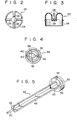
- Fig. 2 is a plan view of the pressure accumulating valve;
- Fig. 3 is a longitudinal sectional view of the pressure accumulating valve;
- Fig. 4 is a plan view of the air suction valve; and
- Fig. 5 is a perspective view of the release means.
- As shown in Fig. 1, a
dispenser 10 with an air pump mechanism comprises avalve housing 14 attached to the top of ametallic container 12 and acylinder 16 attached to the bottom of the container. Thevalve housing 14 contains internally a conventional spraying valve (not shown), and the valve will be released by pushing downwards apush button 18 which is attached at the top of thevalve housing 14 and is also used for a nozzle. A suction tube 20, through which fluid to be sprayed, which is contained in thecontainer 12, passes to the spraying valve, is attached at the bottom of thevalve housing 14. Therefore, by pushing thepush button 18 downwards, the internal part of thecontainer 12 will be opened to atmosphere through the spraying valve, and this allows spraying. Acover housing 21 is detachably attached so as to cover thepush button 18 at the top of thecontainer 12. - The
cylinder 16 is fitted with a tighteningring 19 to the curl edge at the bottom of thecontainer 12 and is extended into the container. Thecylinder 16 includes apressure accumulating valve 22 at the internal end. Thepressure accumulating valve 22 is a one-way valve which allows air flow only into the internal part of thecontainer 12, and as shown in Figs. 2 and 3, the valve has a axiallyflexible valve body 28 which is connected to abody 24 through fourflexible pieces 26. Attachment of thecylinder 16 to thecontainer 12 may be screwed instead of fitted. In this case, supply of the fluid into thecontainer 12 may be easily carried out. - As shown in Fig. 1, the
cylinder 16 contains ahollow piston 30 which can move freely along the internal surface of the cylinder. Anair pump mechanism 31 is composed of thecylinder 16 and thepiston 30. At the internal end, thepiston 30 includes anair suction valve 34 which is a one-way valve allowing air flow into apressure chamber 32 formed by thecylinder 16 and the piston. Theair suction valve 34, as shown in Fig. 4, includes avalve body 40 which is axially flexible and is connected with threeflexible pieces 38 to abody 36, and a skirt-like seal piece 42 formed on the periphery of thebody 36. As shown in Fig. 1, thevalve body 40 is installed at the location a little apart from the upper end of thepiston 30 serving as a valve seat and prevents chattering of the valve body during the drawing stroke of the piston. It is a matter of course that thevalve 34 will be closed by thevalve body 40 being pushed and contacting the upper end of the piston by compressed air generated in thepressure chamber 32 during the pushing stroke of thepiston 30. Thepiston 30 has a stopper, theinclined surface 44 for example, in it's internal part, and theinclined surface 44 is, as described later, formed so as to be able to contact theshoulder 52 of thestem member 48. Thestopper 44 may be axially moved and located at the center or outer end of the piston instead of at the internal end of the piston as shown in Fig. 1. Thedispenser 10 further comprises a release means·46. As shown in Fig. 5, the releases means 46 includes anelastic piece 50 having axially flexible elasticity such as the cylindrical part with bottom and astem member 48 which has a cross- shaped section and is attached to the bottom of thecylindrical part 50 at it's one end. Thestem member 48 has aninclined shoulder 52 at the internal end in an adjacent position, and also has the pushing part, such as acylindrical part 54, at the internal end, and theshoulder 52 is formed so as to be able to contact theinclined surface 44 of thepiston 30, and thecylindrical part 54 is formed so as to be able to push thevalve body 40 of theair suction valve 34. - The
cylindrical part 50 with bottom comprises a plurality of air-inlet holes 55 for instance, four, and is, as shown in Fig. 1, fitted with the bottom of thecylinder 30. Thestem member 48 attached to thecylindrical part 50 extends into thepiston 30, pushing the bottom of thecylindrical part 50, thestem member 48 is raised up to contact thecylindrical part 54 with thevalve body 40, and the valve body is pushed upwards. Upward movement of thestem member 48 is limited by contacting theshoulder 52 with theinclined surface 44. - On the other hand, the
piston 30 will be joined as loading and unloading can be carried out freely by joining theannular joint 60 directly or indirectly to the curl edge of thecontainer 12 with the tighteningring 19. Needless to say, the means to lock thepiston 30 to thecontainer 12 during spraying operation of thedispenser 10 are not limited to the above-mentioned construction using the curl edge, and other various constructions, for example a construction to use a joining groove and a joining projection etc, will be available. - The
dispenser 10 constructed as mentioned above is operated in the following manner. - First, removing the joint'between the annular joint 60 of the piston and the curl edge of the container, the
piston 30 will be reciprocated in thecylinder 16. At this time the release means 46 will move together with thepiston 30, and theair suction valve 34 will not be released. The drawing stroke of thepiston 30 will increase the inner volume of thepressure chamber 32 and pressure will become negative in the pressure chamber. For that reason, thevalve body 40 will be moved toward thepressure chamber 32, and theair suction valve 34 will be released and the skirt-like seal piece 42 will be deformed simultaneously. Air in thecylinder 16 and air flowed into thepiston 30 through air-inlet holes 55 will flow into thepressure chamber 32 through the skirt-like seal piece 42 and thevalve body 40. After that, the pushing stroke of thepiston 30 will compress air in thepressure chamber 32 and the air will flow into thecontainer 12 through thepressure accumulating valve 22 to be stored at high pressure. Repetition of the above reciprocating operation of thepiston 30 will increase pressure of accumulated air in thecontainer 12. As accumulation of pressure proceeds, compressed air in thecontainer 12 will act as a resisting force against thepiston 30, and the reciprocating motion of the piston will become dull. After the compressed air is fully accumulated, in order for thepiston 30 to be pushed into it's locked position, a large force is required because the pressure of compressed air remaining in thepressure chamber 32 acts as a resisting force against the piston. Then, in Fig. 1, the bottom of thecylindrical part 50 of the release means 46 is pushed upwards. By this operation, thestem member 48 will go up, contacting thecylindrical part 54 with thevalve body 40, pushing the valve body upwards to be apart from thevalve seat 41, and theair suction valve 34 will be released. For this reason, compressed air remaining in thepressure chamber 32 will flow into thepiston 30 and will then be released into the atmosphere through the air-inlet holes 55. The resisting force acting on thepiston 30 is, therefore, removed, and the piston can be easily pushed into the locked position. - After locking the
piston 30, if thepush button 18 is lowered, the spraying valve (not shown) will be opened and fluid pushed by compressed air accumulated in thecontainer 12 will go up through the suction tube 20 and will be continually sprayed outwards through the nozzle (not shown). - In this invention, as mentioned above, the
stem member 48 does not contribute at all to watertightness maintaining of theair suction valve 34. Thestem member 48 only acts to release the watertightness by contacting thevalve body 36 of theair suction valve 34 when theelastic piece 50 is moved toward theair suction valve 34. Since the travelling length of theelastic piece 50 can be set to sufficient length, thestem member 48 does not require accuracy in dimensions and assembly. Further, the dispenser may be embodied as a foamer by setting a barrier in the fluid pass instead of the spraying valve used in the above example.
Claims (4)
Applications Claiming Priority (2)
| Application Number | Priority Date | Filing Date | Title |
|---|---|---|---|
| JP137795/81U | 1981-09-17 | ||
| JP1981137795U JPS6028529Y2 (en) | 1981-09-17 | 1981-09-17 | Pressure accumulating type sprayer |
Publications (3)
| Publication Number | Publication Date |
|---|---|
| EP0075224A2 true EP0075224A2 (en) | 1983-03-30 |
| EP0075224A3 EP0075224A3 (en) | 1983-08-03 |
| EP0075224B1 EP0075224B1 (en) | 1985-06-19 |
Family
ID=15207027
Family Applications (1)
| Application Number | Title | Priority Date | Filing Date |
|---|---|---|---|
| EP82108383A Expired EP0075224B1 (en) | 1981-09-17 | 1982-09-11 | Dispenser with an air pump mechanism |
Country Status (7)
| Country | Link |
|---|---|
| US (1) | US4492320A (en) |
| EP (1) | EP0075224B1 (en) |
| JP (1) | JPS6028529Y2 (en) |
| AU (1) | AU538548B2 (en) |
| DE (1) | DE3264293D1 (en) |
| ES (1) | ES267277U (en) |
| ZA (1) | ZA826610B (en) |
Cited By (8)
| Publication number | Priority date | Publication date | Assignee | Title |
|---|---|---|---|---|
| WO1990006814A1 (en) * | 1988-12-15 | 1990-06-28 | Inter Airspray Sweden Aktiebolag | Method of assembling a pressurized dispenser and a pressurized dispenser for carrying out said method |
| DE4026023A1 (en) * | 1990-08-17 | 1992-02-27 | Joachim Mogler | TAP DEVICE FOR KEGS |
| EP0520285A1 (en) * | 1991-06-26 | 1992-12-30 | Robert Finke GmbH & Co. KG | Container for the spraying of fluid |
| US5267674A (en) * | 1991-06-26 | 1993-12-07 | Robert Finke Gmbh & Co. Kg | Container for the spray-dispensing of liquid |
| EP0602389A1 (en) * | 1992-12-17 | 1994-06-22 | Wella Aktiengesellschaft | Liquid spraying or foam delivering apparatus |
| FR2703980A1 (en) * | 1993-04-13 | 1994-10-21 | Helispire Sarl | Device for dispensing or spraying small quantities of fluid |
| EP0631824A1 (en) * | 1993-06-25 | 1995-01-04 | ROBERT FINKE GmbH & Co. KG | Container for dispensing liquid |
| US5480069A (en) * | 1993-07-23 | 1996-01-02 | Chesebrough-Pond's Usa Co. | Aerosol dispensing device |
Families Citing this family (18)
| Publication number | Priority date | Publication date | Assignee | Title |
|---|---|---|---|---|
| DE3742466C2 (en) * | 1987-12-15 | 1993-12-02 | Vorwerk Co Interholding | Mixing device in spray cans for mixing suspensions containing solids |
| DE8907349U1 (en) * | 1989-06-16 | 1989-08-10 | Icis-Tirestar Vertrieb Montage Service W. Von Duesterlho Kg, 6799 Herschweiler-Pettersheim, De | |
| DE4004653A1 (en) * | 1990-02-15 | 1991-08-22 | Alfred Von Schuckmann | LIQUID SPRAYING DEVICE |
| US5323935A (en) * | 1992-02-21 | 1994-06-28 | The Procter & Gamble Company | Consumer product package incorporating a spray device utilizing large diameter bubbles |
| DE4305130A1 (en) * | 1992-06-16 | 1993-12-23 | Raku Gmbh | Process for manufacturing a container |
| WO1994004437A1 (en) * | 1992-08-24 | 1994-03-03 | Omnific International Ltd. | Aerosol container |
| US5348198A (en) * | 1992-08-24 | 1994-09-20 | Omnific International Ltd. | Refillable aerosol container |
| US5316187A (en) * | 1992-11-24 | 1994-05-31 | The Procter & Gamble Company | Pump pistons for pressurizing liquid dispensing containers |
| CH687645A5 (en) * | 1993-02-11 | 1997-01-15 | Sigg Ag Haushaltgerote | Air-pump pressurising heater fuel tank |
| US5462099A (en) * | 1994-01-28 | 1995-10-31 | S. C. Johnson & Son, Inc. | System and method for pressurizing dispensing containers |
| US5570840A (en) * | 1994-10-14 | 1996-11-05 | Fourth And Long, Inc. | Hand-held spraying apparatus |
| US5749502A (en) * | 1996-01-17 | 1998-05-12 | Hinds; Frank C. | Advanced aerosol container |
| US5865350A (en) * | 1997-01-24 | 1999-02-02 | Pure Vision International L.L.P. | Spray bottle with built-in pump |
| US5957333A (en) * | 1998-01-26 | 1999-09-28 | Pure Vision International L.L.P. | Aerosol spray container with improved dispensing valve assembly |
| US5921439A (en) * | 1998-01-26 | 1999-07-13 | Pure Vision International L.L.P. | Aerosol spray container with improved dispensing valve assembly |
| US6006388A (en) * | 1998-04-14 | 1999-12-28 | Young; Cecil Blake | Dispenser for dispensing concentrated liquid soap to industrial cleaning apparatuses |
| US6193115B1 (en) * | 1999-08-06 | 2001-02-27 | Ajit Kumar Das | Insulated and easy to pump reusable mist sprayer |
| GB0328003D0 (en) * | 2003-12-03 | 2004-01-07 | Quill Internat Ind Plc | A mist-spraying apparatus |
Citations (4)
| Publication number | Priority date | Publication date | Assignee | Title |
|---|---|---|---|---|
| US1745024A (en) * | 1929-04-18 | 1930-01-28 | Malone John Lafayette | Hydraulic jack |
| FR725121A (en) * | 1931-03-23 | 1932-05-09 | Syringe which can be used as a lubricating burette, vaporizer, etc. | |
| US3955720A (en) * | 1972-11-15 | 1976-05-11 | Malone David C | Low pressure dispensing apparatus with air pump |
| EP0037035A1 (en) * | 1980-03-31 | 1981-10-07 | Canyon Corporation | Air-pressurized sprayer |
Family Cites Families (1)
| Publication number | Priority date | Publication date | Assignee | Title |
|---|---|---|---|---|
| US4165025A (en) * | 1977-09-21 | 1979-08-21 | The Continental Group, Inc. | Propellantless aerosol with fluid pressure generating pump |
-
1981
- 1981-09-17 JP JP1981137795U patent/JPS6028529Y2/en not_active Expired
-
1982
- 1982-09-08 AU AU88130/82A patent/AU538548B2/en not_active Ceased
- 1982-09-09 US US06/416,305 patent/US4492320A/en not_active Expired - Lifetime
- 1982-09-09 ZA ZA826610A patent/ZA826610B/en unknown
- 1982-09-11 DE DE8282108383T patent/DE3264293D1/en not_active Expired
- 1982-09-11 EP EP82108383A patent/EP0075224B1/en not_active Expired
- 1982-09-15 ES ES1982267277U patent/ES267277U/en active Pending
Patent Citations (4)
| Publication number | Priority date | Publication date | Assignee | Title |
|---|---|---|---|---|
| US1745024A (en) * | 1929-04-18 | 1930-01-28 | Malone John Lafayette | Hydraulic jack |
| FR725121A (en) * | 1931-03-23 | 1932-05-09 | Syringe which can be used as a lubricating burette, vaporizer, etc. | |
| US3955720A (en) * | 1972-11-15 | 1976-05-11 | Malone David C | Low pressure dispensing apparatus with air pump |
| EP0037035A1 (en) * | 1980-03-31 | 1981-10-07 | Canyon Corporation | Air-pressurized sprayer |
Cited By (9)
| Publication number | Priority date | Publication date | Assignee | Title |
|---|---|---|---|---|
| WO1990006814A1 (en) * | 1988-12-15 | 1990-06-28 | Inter Airspray Sweden Aktiebolag | Method of assembling a pressurized dispenser and a pressurized dispenser for carrying out said method |
| US5209379A (en) * | 1988-12-15 | 1993-05-11 | Inter Airspray Sweden Aktiebolag | Method of assembling a pressurized dispenser and a pressurized dispenser for carrying out said method |
| DE4026023A1 (en) * | 1990-08-17 | 1992-02-27 | Joachim Mogler | TAP DEVICE FOR KEGS |
| EP0520285A1 (en) * | 1991-06-26 | 1992-12-30 | Robert Finke GmbH & Co. KG | Container for the spraying of fluid |
| US5267674A (en) * | 1991-06-26 | 1993-12-07 | Robert Finke Gmbh & Co. Kg | Container for the spray-dispensing of liquid |
| EP0602389A1 (en) * | 1992-12-17 | 1994-06-22 | Wella Aktiengesellschaft | Liquid spraying or foam delivering apparatus |
| FR2703980A1 (en) * | 1993-04-13 | 1994-10-21 | Helispire Sarl | Device for dispensing or spraying small quantities of fluid |
| EP0631824A1 (en) * | 1993-06-25 | 1995-01-04 | ROBERT FINKE GmbH & Co. KG | Container for dispensing liquid |
| US5480069A (en) * | 1993-07-23 | 1996-01-02 | Chesebrough-Pond's Usa Co. | Aerosol dispensing device |
Also Published As
| Publication number | Publication date |
|---|---|
| JPS5843966U (en) | 1983-03-24 |
| ZA826610B (en) | 1983-07-27 |
| DE3264293D1 (en) | 1985-07-25 |
| US4492320A (en) | 1985-01-08 |
| ES267277U (en) | 1984-10-01 |
| AU538548B2 (en) | 1984-08-16 |
| EP0075224A3 (en) | 1983-08-03 |
| EP0075224B1 (en) | 1985-06-19 |
| JPS6028529Y2 (en) | 1985-08-29 |
| AU8813082A (en) | 1983-03-24 |
Similar Documents
| Publication | Publication Date | Title |
|---|---|---|
| EP0075224B1 (en) | Dispenser with an air pump mechanism | |
| CA1099674A (en) | Manually operated liquid dispensing device | |
| US4530449A (en) | Liquid spraying device | |
| EP0179853B1 (en) | Pump for dispensing liquid from a container | |
| JPH0335884Y2 (en) | ||
| EP0755305B1 (en) | Manually operated reciprocating liquid pump | |
| US6006949A (en) | Manually operated reciprocating liquid pump with sealing vent opening | |
| EP0301615A2 (en) | Delivery pump which can be applied to containers of fluids | |
| US5816447A (en) | Non-aerosol pump spray apparatus | |
| EP0020840A1 (en) | Manual liquid dispensing device for spraying liquid | |
| US4389003A (en) | Sliding inlet seal for an atomizing pump dispenser | |
| EP0407494A1 (en) | Sealing pump. | |
| JPS63502409A (en) | non-throttle discharge pump | |
| US5524793A (en) | Dispensing pump which is lockable and sealable for transporation and storage | |
| EP0265270B1 (en) | A non throttling discharge pump assembly | |
| US4010874A (en) | Pump for hand-held dispensers | |
| GB2141185A (en) | Manually actuated pump adapted for pressure filling | |
| CA1069091A (en) | Spray pump assembly | |
| JP2002195152A (en) | Material distributing pump | |
| JPS6040900B2 (en) | dispenser | |
| JPS6041567A (en) | Metering valve | |
| US5209379A (en) | Method of assembling a pressurized dispenser and a pressurized dispenser for carrying out said method | |
| EP0037035A1 (en) | Air-pressurized sprayer | |
| CA1153992A (en) | Air-pressurized sprayer | |
| HU184997B (en) | Valve arrangement |
Legal Events
| Date | Code | Title | Description |
|---|---|---|---|
| PUAI | Public reference made under article 153(3) epc to a published international application that has entered the european phase |
Free format text: ORIGINAL CODE: 0009012 |
|
| AK | Designated contracting states |
Designated state(s): DE FR GB IT NL |
|
| 17P | Request for examination filed |
Effective date: 19830226 |
|
| PUAL | Search report despatched |
Free format text: ORIGINAL CODE: 0009013 |
|
| AK | Designated contracting states |
Designated state(s): DE FR GB IT NL |
|
| ITF | It: translation for a ep patent filed |
Owner name: JACOBACCI & PERANI S.P.A. |
|
| GRAA | (expected) grant |
Free format text: ORIGINAL CODE: 0009210 |
|
| AK | Designated contracting states |
Designated state(s): DE FR GB IT NL |
|
| REF | Corresponds to: |
Ref document number: 3264293 Country of ref document: DE Date of ref document: 19850725 |
|
| ET | Fr: translation filed | ||
| PLBE | No opposition filed within time limit |
Free format text: ORIGINAL CODE: 0009261 |
|
| STAA | Information on the status of an ep patent application or granted ep patent |
Free format text: STATUS: NO OPPOSITION FILED WITHIN TIME LIMIT |
|
| 26N | No opposition filed | ||
| PGFP | Annual fee paid to national office [announced via postgrant information from national office to epo] |
Ref country code: GB Payment date: 19930901 Year of fee payment: 12 |
|
| PGFP | Annual fee paid to national office [announced via postgrant information from national office to epo] |
Ref country code: FR Payment date: 19930915 Year of fee payment: 12 |
|
| PGFP | Annual fee paid to national office [announced via postgrant information from national office to epo] |
Ref country code: DE Payment date: 19930928 Year of fee payment: 12 |
|
| ITTA | It: last paid annual fee | ||
| PGFP | Annual fee paid to national office [announced via postgrant information from national office to epo] |
Ref country code: NL Payment date: 19930930 Year of fee payment: 12 |
|
| PG25 | Lapsed in a contracting state [announced via postgrant information from national office to epo] |
Ref country code: GB Effective date: 19940911 |
|
| PG25 | Lapsed in a contracting state [announced via postgrant information from national office to epo] |
Ref country code: NL Effective date: 19950401 |
|
| GBPC | Gb: european patent ceased through non-payment of renewal fee |
Effective date: 19940911 |
|
| NLV4 | Nl: lapsed or anulled due to non-payment of the annual fee | ||
| PG25 | Lapsed in a contracting state [announced via postgrant information from national office to epo] |
Ref country code: FR Effective date: 19950531 |
|
| PG25 | Lapsed in a contracting state [announced via postgrant information from national office to epo] |
Ref country code: DE Effective date: 19950601 |
|
| REG | Reference to a national code |
Ref country code: FR Ref legal event code: ST |